Abstract
This study examines the combined heat transfer by thermal conduction, natural convection and surface radiation in the porous char layer that is formed from the intumescent coating under fire. The results show that some factors, such as the Rayleigh number, conductivity ratio, emissivity, radiation–conduction number, void fraction and heating mode have a certain effect on the total heat transfer. In addition, the natural convection of the air in the cavity always inhibits surface radiation among the solid walls and thermal conduction, and the character of the total heat transfer is the competition result of the three heat transfer mechanisms.
1. Introduction
In the field of steel structure, the improvement of fire resistance is always a key problem. The inherent weakness of steel structures that cannot maintain their strength and stiffness at high temperatures is often addressed by applying insulation to their exposed surfaces, which delays the transfer of heat to the internal structure and, thus, increases the time required for the critical temperature of the steel structure to be reached [1]. Among the commonly used passive fire prevention measures, intumescent coatings have a strong application competitiveness, because they can provide efficient fire protection with a relatively thin thickness, and at the same time are practical and aesthetically pleasing [2]. Intumescent coatings generally form a porous char layer during their degradation and expansion under high temperature. The char layer can often act as an efficient thermal barrier between the heat source and the steel structure [3].
Previous research on intumescent coatings can be classified into two types. One type is based on the improvement of the chemical components. This kind of research mainly considers the effect of the main components of the intumescent coating in order to find their best chemical composition. Reshetnikov et al. [4,5,6] found that the optimum weight ratio of ammonium polyphosphate and polyol for both thermal insulation and the oxygen index was 7:3. However, the mechanical stability of the char layer performed poorly at the optimum ratio and the char layer was easier to crush, which had a negative effect on thermal insulation. Gottfried et al. [7] found that the refractory fibers, such as alumina- and silica-based fibers, were able to improve thermal insulation performance when added to intumescent coatings. Research by Bourbigot et al. [8] showed that adding boric acid to an APP–epoxy-based intumescent coating led not only to more efficient thermal protection, but also to better mechanical resistance. Wang et al. [9] compared the performance of classical intumescent coatings and EG-based intumescent coatings. The oxidation stability and thermal insulation properties of EG-based coating were better than those of classical intumescent coatings. Many attempts have been made to improve thermal insulation by adding nano-clays and other nano-dimensional inorganic fillers. A brief review of fire-retardant nano-composite coatings was conducted in a book by Koo and Pilato [10]. Studies in China [11] showed that adding up to 1.5% phyllosilicate clay or layered double hydroxides (both with nanometer-thick layers) improved the thermal barrier by the char layer.
The second type of research on intumescent coatings is focused on the mathematical models of their thermal response behavior under high temperature. This kind of research is based on the understanding of heat transfer and expansion mechanisms. Cagliostro et al. [12] developed a semi-empirical model of intumescent coating that introduced an empirical parameter as the expansion coefficient, which was used to replace the thermal conductivity for the solution. Buckmaster et al. [13,14] proposed a “front” model to predict the thermal response behavior of the intumescent coatings. The premise of this model was that the release of the gas products, the formation of pores and expansion all occurred at a specific temperature. Butler et al. [15] proposed a three-dimensional mathematical model which combined the growth of the pores and the heat transfer process. However, the number of pores in the model calculation process must be used as input value, and the expansion of the coatings was a simple superposition of all the pores, which led to a lack of reliability. Blasi et al. [16,17] developed a mathematical model, which described the main process of the degradation and expansion. Two empirical parameters were required for simulation calculation, the amount of gas trapped by the molten mass and the resulting expansion amount. Based on the research of Blasi, Zhang et al. [18,19] focused on the expansion temperature range and expansion amount of the intumescent coatings. They assumed that expansion amount was determined by the amount of trapped gas in the expansion process, and introduced an empirical parameter to represent the gas retention ratio. In addition, a series of experiments were conducted to verify the validity of the model. Yuan and Wang [20,21] was another group that attempted to predict the expansion behavior of intumescent coatings by taking the released gas into consideration. Although they achieved some success, some necessary input data for the model were difficult to quantify, which restricted its wide application. Staggs et al. [22] established a mathematical model to describe the heat transfer and expansion process. The model was developed in conjunction with some tests, including standard and non-standard furnace tests and mass loss calorimeter (MLC) tests. Barak et al. [23,24] used the bubble growth model proposed by Amon and Denson [25] to describe the expansion behavior of the intumescent coatings, and calculated the expansion rate based on the assumption that the molten mass retained all released gases. The validity of the method was proved by the fire test [18,19] and then applied to assess how the steel thickness, coating thickness and fire conditions affected thermal insulation performance. Bartholmai et al. [26] carried out a series of experiments in a cone calorimeter, and took the temperature–time curve of the protected steel plate measured in the experiment as input data to calculate the equivalent thermal conductivity of the intumescent coatings. Li et al. [27] proposed the use of a constant equivalent thermal conductivity within a certain temperature range to predict the temperature of the protected steel. Staggs [28] built a numerical model by combining the digital image and the void fraction information of the fully expanded char layer to calculate the effective thermal conductivity by using the finite element method.
Most of the above-mentioned researches focused on the overall thermal insulation performance of the intumescent coatings but ignored the combined heat transfer mechanisms in the char layers. In fact, the char layer formed from the intumescent coating is the key factor in thermal insulation performance. Based on engineering demand, this research aims to present a numerical study of the combined heat transfer by conduction, natural convection and surface radiation in the char layer formed from the intumescent coatings under fire [29,30]. The study may also be regarded as an extension of a recent study [31], presenting a more detailed discussion of the effect of the Rayleigh number, conductivity ratio, emissivity, radiation–conduction number, void fraction and heating mode on the total heat transfer in the char layer. Furthermore, the results of the study can be also applied to other engineering situations, such as shells, sandwich structures, bricks and foams.
2. Problem Statement
2.1. Physical Description
The char layer formed from the intumescent coatings at high temperatures is a kind of porous structure, and the representative cell can be used to characterize the whole structure. A typical representative cell [31] is shown in Figure 1. The squared cell and the cavity geometry are used for the following reasons: previous studies in this field have used these two models (a squared cell with a circular cavity) and have proven that the shape of the cavity has a slight effect on the thermal transfer mechanisms. In addition, the squared cell and the cavity geometry are able to guarantee a high void fraction in numerical modeling. The combined heat transfer in the representative cell is, in fact, the natural convection of the air inside a closed cavity coupled with heat conduction and radiation. The size of the structure is L × L, and the left and right sides of the structure are considered isothermal and maintained at Th and Tc, while the top and bottom sides are regarded as adiabatic. The section line part is the solid layer, with a certain thickness and thermal conductivity. The rest of the structure is a two-dimensional square cavity with a length of l. The cavity is filled with air, the air flow is considered laminar and the Boussinesq hypothesis is used to simplify the simulation calculation. The solid–air interfaces are taken as no slip conditions, and are assumed as diffuse–gray with an emissivity of ε. In addition, the air is regarded as non-participating due to its weak effect on radiation.
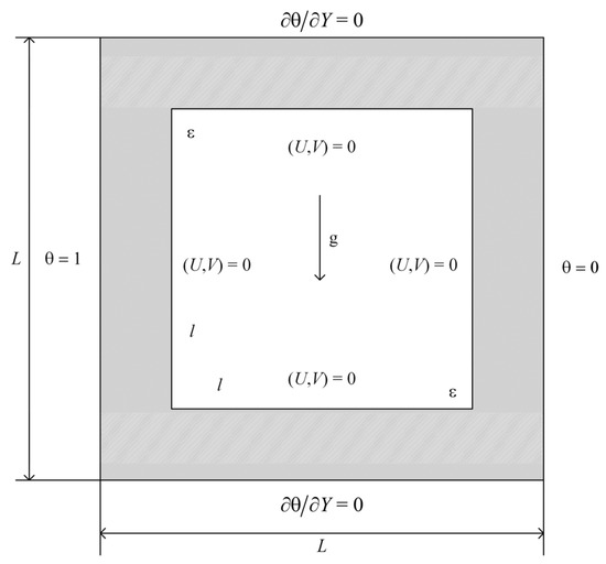
Figure 1.
A typical representative cell of the char layer.
2.2. Governing Equations
For the sake of brevity and generality, the governing equations are written in their dimensionless form by considering the steady state regime. The equation of heat conduction in the solid walls is
where is the thermal diffusion coefficient ratio of the solid to the air.
For the air in the cavity, the conservation equations of mass, momentum, and energy are expressed as follows:
where U and V are the dimensional velocity in X and Y directions, P is the dimensional pressure, θ is the dimensional temperature and Ra and Pr are the Rayleigh number and the Prandtl number, respectively. The dimensional parameters are defined as
2.3. Boundary Conditions
At the top and bottom outside walls,
At the left and right outside walls,
At the hot solid–air interfaces,
where kr is the thermal conductivity ratio of the solid to the air.
The velocity at the solid–air interfaces is
2.4. Surface Radiation
When surface radiation among the solid walls is taken into account, the walls are assumed as diffuse and gray, and the air is regarded as a non-participating media due to its slight effect. Therefore, the thermal boundary condition at the hot solid–air interfaces turns into the following:
where Nr is the radiation to conduction number (defined as ) and is the dimensional radiation heat flux defined by
where , is the emissivity of the solid walls, is the view factor from the surface to and is the dimensionless radiosity of the solid walls.
The local Nusselt number of the hot solid–air interfaces is employed for describing the heat transfer characteristic near the interfaces, and the convection and radiation local Nusselt numbers are defined, respectively, as,
The average convective, radiative and total Nusselt numbers of the hot solid–air interfaces are defined, respectively, as
3. Numerical Solution and Code Validation
The numerical calculation method adopted in this study is based on the Galerkin method, which is a kind of finite element method, solved by the Comsol software (version 5.5). In the solution process, the parallel direct solver (Pardiso) is adopted, and the convergence accuracy of relative tolerance is set as 10−6. The built-in grid module is used for mesh plotting, and a typical grid structure is shown in Figure 2; the level of the grids is finer and the total number of grids is 3024. The grids are dense close to the sides, but sparse away from the sides due to the existence of the boundary layer, which is able to achieve both the high precision requirement and calculation efficiency. In order to verify the numerical calculation method adopted, the natural convection of the air in a cavity has been calculated and the average Nusselt number obtained at the high-temperature wall, both of which are comparable with those in the literature [32]. Table 1 gives a comparison between the average Nusselt numbers. It can be seen that the maximum error is only 0.41% for Ra = 106 and the minimum error is 0.13% for Ra = 104, which indicates that the method adopted in this paper is correct. From Table 2, it can be seen that the average Nusselt numbers change little for different grids for Ra = 105; that is, the average Nusselt numbers are largely independent of a grid’s level. By comprehensive consideration of the calculation accuracy and cost, the extra fine level of the grids was chosen in this paper.
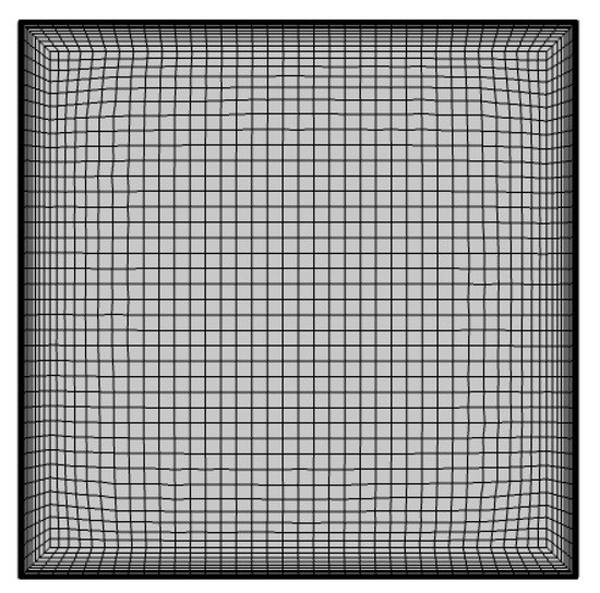
Figure 2.
Computational grid structure of the model.

Table 1.
Comparison of average Nusselt numbers for different Rayleigh numbers.

Table 2.
Comparison of average Nusselt numbers for different grids at Ra = 105.
4. Results and Discussions
In this study, the effects of natural convection, thermal conduction, thermal radiation, geometric parameters and heating mode on the total heat transfer in the representative cell are numerically investigated. The results are obtained in the following ranges of the associated dimensionless groups: the Rayleigh number (from the range of 102–106), the thermal conductivity ratio of solid to air (10−1–103), the emissivity (0.2–1), the radiation to conduction number (10−1–103), the void fraction (0.1–0.9) and the heating mode, heating from the bottom or the top.
4.1. The Effect of the Rayleigh Number
Figure 3 shows the isothermals (on the left) and streamlines (on the right) for Kr = 10, ε = 0, ϕ = 0.5 and Pr = 0.71, with Ra = 102, 103, 104, 105 and 106. It can be seen that, for Ra = 102 and Ra = 103, the isothermals are almost vertically distributed. From the streamlines, the air flow is very weak due to the weak buoyancy force compared to the viscous force, which indicates that the heat transfer in the cavity is dominated by thermal conduction. As Ra increases to 104, the isothermals in the cavity become curved, which represents the enhancement of the air flow, and the transition from conduction to natural convection takes place. For Ra = 105, the isothermals are almost horizontally distributed of the cavity and more intensive near the interface, for the most part. From the streamlines, two vortexes are formed due to the enhanced buoyancy force. For Ra = 106, the streamlines turn more chaotic, and there is a tendency for turbulent flows to form. In these cases, natural convection tends to be the main mode of the total heat transfer.
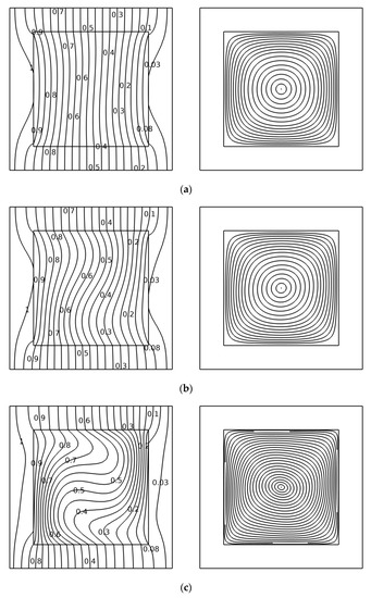
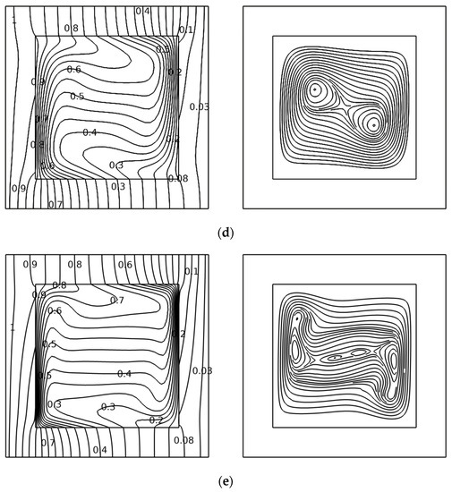
Figure 3.
Streamlines and isothermals obtained for (a) Ra = 102, Wmax = 0.5111, (b) Ra = 103, Wmax = 4.804, (c) Ra = 104, Wmax = 24.808, (d) Ra = 105, Wmax = 80.813 and (e) Ra = 106, Wmax = 229.87.
Figure 4 shows the evolution of the average convective number of the hot interface as a function of Ra. It can be seen that increases with an increasing Ra. From Ra = 102 to Ra = 103, remains almost unchanged, and its growth rate becomes faster with increasing Ra. At last, the growth rate of reaches a peak in the range of Ra = 105 to Ra = 106. This means that with an increasing Ra, the fraction of heat transfer by natural convection increases and Ra has a more significant impact on natural convection when it is at a high value.
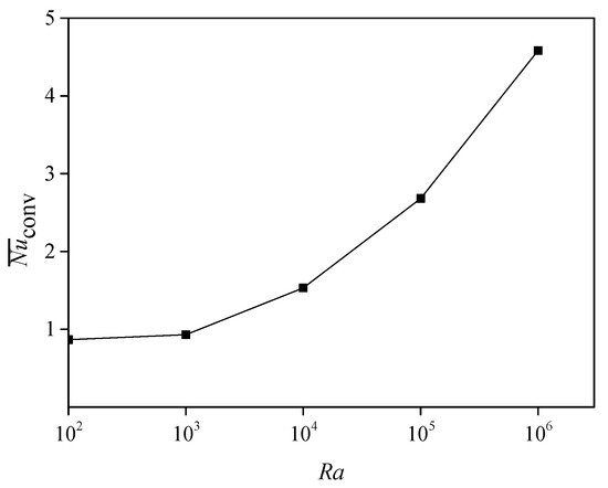
Figure 4.
Variations of the average Nusselt number as a function of Ra.
4.2. The Effect of the Thermal Conductivity Ratio of Solid to Air
Figure 5 shows the isothermals (on the left) and streamlines (on the right) for Ra = 105, ε = 0, ϕ = 0.5 and Pr = 0.71, with Kr = 10−1, 100, 101, 102 and 103. For Kr = 10−1, the isothermals are dense in the solid walls and spare in the cavity. This is because the large thermal resistance of the solid walls leads to a small temperature difference in the cavity. As a result, the buoyancy force becomes weak, and thermal conduction dominates the heat transfer in the cavity. The above conclusions are also proved correct by the streamlines, which are uniformly distributed in the cavity. As Kr increases, the isothermals in the solid walls become spare due to the reduction of the thermal resistance. In the cavity, the isothermals are most commonly horizontally distributed, but have a vertical distribution near the hot interface. This is because the boundary layer is going to be formed near the wall. From the streamlines, two vortexes are formed due to the enhanced buoyancy force and the maximum velocity of the air becomes greater. This indicates that, with the increase in Kr, natural convection is strengthened and gradually occupies the leading role. In addition, from the isothermals for Kr = 100 and Kr = 101, the transition from conduction to natural convection of the air takes place and is almost accomplished as Kr increases to 102. In the case of Kr = 102 to Kr = 103, heat transfer is dominated by natural convection, judging from the patterns.
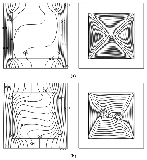
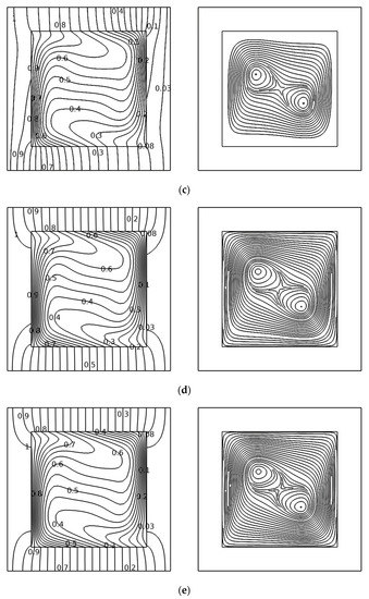
Figure 5.
Streamlines and isothermals obtained for (a) Kr = 0.1, Wmax = 19.782, (b) Kr = 1, Wmax = 46.635, (c) Kr = 10, Wmax = 80.813, (d) Kr = 100, Wmax = 92.874 and (e) Kr = 1000, Wmax = 94.664.
Figure 6 shows the evolution of the average convective Nusselt number of the hot interface as a function of Kr. It can be seen that increases with increasing Kr from 10−1 to 101, and remains stable from 101 to 103. This is because the increasing Kr increases the temperature difference and thus causes stronger natural convection. From the figure, the growth rates of are as different as those of Kr, in a different scope. From Kr = 100 to Kr = 101, the growth rate is the fastest, and from Kr = 101 to Kr = 103, the change of turns to be extremely small. This indicates that Kr has a positive effect on natural convection, but the effect is close to a limit as Kr exceeds 102.
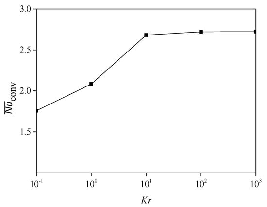
Figure 6.
Variations of the average Nusselt number as a function of Kr.
4.3. The Effect of Emissivity
When surface radiation among the walls is taken into consideration, three additional parameters (the wall emissivity ε, radiation to conduction number Nr and temperature ratio G) are used to characterize the effect of radiation. Figure 7 shows the isothermals (on the left) and streamlines (on the right) for Ra = 105, Kr = 10, G = 1.2, Nr = 10, ϕ = 0.5 and Pr = 0.71, with ε = 0.2, 0.4, 0.6, 0.8 and 1. For ε = 0.2, the isothermals are horizontally distributed in the greatest amount of space of the cavity, but have an intense vertical distribution near the hot interface. As ε increases, the isothermals in the cavity turn sparse and there is a general tendency of the levelness of the isothermals to reduce slowly. This indicates that natural convection is weakened as ε increases; this is because the increasing ε is able to strengthen surface radiation. From the streamlines, two vortexes formed for ε = 0.2. As ε increased, the vortexes become smaller and even has a tendency for disappearance for ε = 1. This means natural convection in the cavity is inhibited by surface radiation, and the decreasing maximum velocity also proves this conclusion.
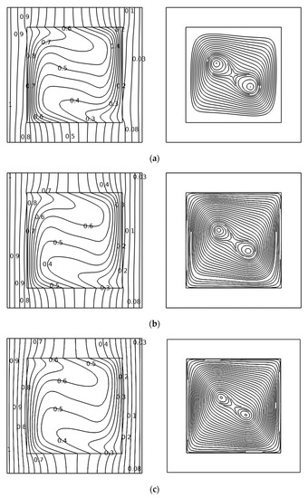
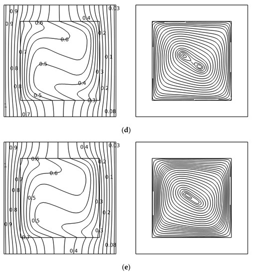
Figure 7.
Streamlines and isothermals obtained for (a) ε = 0.2, Wmax = 76.364, (b) ε = 0.4, Wmax = 71.407, (c) ε = 0.6, Wmax = 66.759, (d) ε = 0.8, Wmax = 62.328 and (e) ε = 1, Wmax = 58.528.
Figure 8 shows the evolution of the local convective Nusselt number of the interface as a function of ε. It is easy to find that decreases with increasing ε and that the change of has a similar trend from ε = 0.1 to ε = 0.9. In addition, the maximum occurs in the lower half of the cavity and the minimum occurs in the higher half of the cavity. Figure 9 shows the evolution of the average convective, radiative and total Nusselt numbers of the hot interface as a function of ε. It can be seen that increases with increasing ε, but decreases as ε increases. It indicates that the surface radiation of the solid walls is enhanced by an increase in ε, which leads to a more uniform temperature distribution in the cavity. Therefore, the natural convection of the air is weakened due to the decrease of the temperature difference in the cavity. Nevertheless, the increase in means that the total heat transfer is strengthened in the cavity. The reason for this is that in this case, surface radiation has a greater effect on the total heat transfer compared to natural convection.
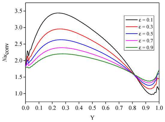
Figure 8.
Variations of the local Nusselt number at different ε.
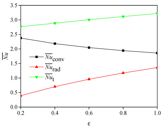
Figure 9.
Variations of the average Nusselt number as a function of ε.
4.4. The Effect of the Radiation to Conduction Number
Figure 10 shows the isothermals (on the left) and streamlines (on the right) for Ra = 105, Kr = 10, ε = 0.6, G = 1.2, ϕ = 0.5 and Pr = 0.71, with Nr = 10−1, 100, 101, 102 and 103. For Nr = 10−1, the isothermals in the cavity are almost horizontally distributed, but have an intense vertical distribution near the hot interface. With the increase in Nr, the horizontally distributed isothermals become vertically distributed, which indicates that the transition from natural convection to conduction and surface radiation takes place. For Nr = 103, the isothermals are all concentrated on the solid walls. In addition, the maximum velocity decreases as Nr increases. This indicates that the air flow becomes weaker with increasing Nr, and natural convection is restrained by surface radiation. It can be seen from the streamlines that for Nr = 1, two vortexes appear in the middle-upper and middle-lower part of the cavity, and the streamlines in the cavity are distributed non-uniformly, which means the air flow is extremely strong. For Nr = 102, the two vortexes vanished, which indicates the air flow is weakened, and the heat transfer is dominated by surface radiation.
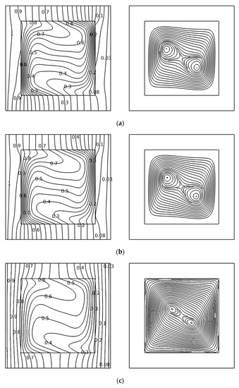
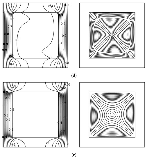
Figure 10.
Streamlines and isothermals obtained for (a) Nr = 10−1, Wmax = 80.698, (b) Nr = 100, Wmax = 79.533, (c) Nr = 101, Wmax = 66.759, (d) Nr = 102, Wmax = 29.962 and (e) Nr = 103, Wmax = 6.1957.
Figure 11 shows the evolution of the average convective, radiative and total Nusselt numbers of the hot interface as a function of Nr. It can be seen that increases with increasing Nr, but decreases with increasing Nr. This indicates that surface radiation among the solid walls is enhanced by an increase in Nr, which leads to a more uniform temperature distribution in the cavity. Therefore, the natural convection of the air is weakened due to the decrease of the temperature difference in the cavity. In addition, at low Nr (from 10−1 to 100) and at high Nr (from Nr = 102 to 103), and had little change compared to the Nr from 100 to 102. This means that the effect of Nr on the total heat transfer reaches a peak for Nr from 100 to 102, and, in the other range, the effect has a limit. In addition, the increase in with increasing Nr indicates that the total heat transfer in the cavity is strengthened and surface radiation plays a leading role at high Nr.
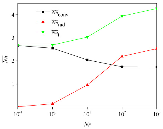
Figure 11.
Variations of the average Nusselt number as a function of Nr.
The emissivity of the porous char layer and the radiation to conduction number have a significant effect on total heat transfer when taking surface radiation into consideration. In order to keep excellent thermal protection performance at high temperature, the designer should take effective measures to make the emissivity lower.
4.5. The Effect of Void Fraction
Figure 12 shows the isothermals (on the left) and streamlines (on the right) for Ra = 105, Kr = 10, ϕ = 0.6, Nr = 10, G = 1.2 and Pr = 0.71, with ϕ = 0.1, 0.3, 0.5, 0.7 and 0.9. The isothermals for all the cases are similarly distributed but different in the fine details. From ϕ = 0.1 to ϕ = 0.9, the isothermals in the greatest part of the cavity are almost horizontally distributed and the levelness of the isothermals becomes higher with increasing ϕ, which indicates that air flow is strengthened. In addition, the isothermals near the interface become more intense. The streamlines turn out to be more chaotic with increasing ϕ, and the maximum velocity increases gradually. For ϕ = 0.1, one vortex in the middle is formed, and for ϕ = 0.3, 0.5, 0.7, 0.9, two vortexes are formed due to the strengthened air flow. This indicates that the natural convection is strengthened by an increase in ϕ.
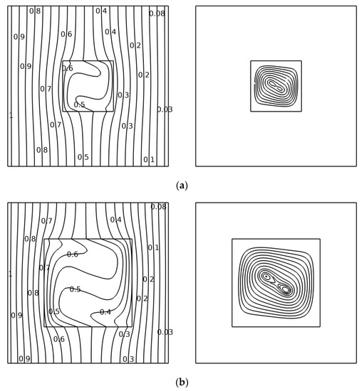
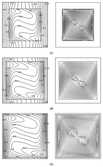
Figure 12.
Streamlines and isothermals obtained for (a) φ = 0.1, Wmax = 59.963, (b) φ = 0.3, Wmax = 63.882, (c) φ = 0.5, Wmax = 66.759, (d) φ = 0.7, Wmax = 70.289 and (e) φ = 0.9, Wmax = 74.105.
Figure 13 shows the evolution of the average convective, radiative and total Nusselt numbers of the hot interface as a function of ϕ. It can be seen that and increases with an increase in ϕ. This demonstrates that the increasing ϕ have a positive effect on both natural convection and surface radiation. The reason for this is that increasing ϕ leads to a large temperature difference in the cavity and changes the characteristic length. Both natural convection and surface radiation are driven by temperature difference and characteristic length. increases with increasing ϕ as a result of and , which represents that the total heat transfer is strengthened in the cavity.
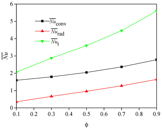
Figure 13.
Variations of the average Nusselt number as a function of ϕ.
The void fraction is a significant parameter that affects the thermal protection performance of the intumescent coatings. With increasing ϕ, thermal conduction is weakened due to low thermal conductivity, whereas natural convection and surface radiation are strengthened. As a consequence, an optimal ϕ exists to guarantee the best thermal protection performance. This is valuable for materials scientists to design better intumescent coatings.
4.6. The Effect of Heating Mode
The above figures show isothermals (on the left) and streamlines (on the right) for Ra = 105, Kr = 10, G = 1.2, Nr = 10, ϕ = 0.5, Pr = 0.71 and ε = 0.6. In Figure 14, the isothermals in the cavity are almost horizontally distributed, which indicates that the heat transfer in the cavity is dominated by heat conduction and surface radiation. The reason for this is that when heating comes from the top, the air near the top has a lower density compared with that near the bottom, and it is difficult to form air circulation. The isothermals are convex in shape at the top and bottom walls of the cavity since the thermal diffusivity of the air is much larger than that of the solid walls. It can be also seen from the streamlines that the air flow is extremely slow, and thus the heat transfer in the cavity resulting from natural convection is not worth considering in this case. In Figure 15, the isothermals in the cavity are non-uniformly distributed and bend inwards, which indicates that the heat transfer in the cavity is dominated by natural convection and surface radiation. This is because when heating from the bottom, the air near the bottom has a lower density compared with that near the top, and it is easy to form air circulation. The streamlines indicate that the air flow is very strong, and heat transfer in the cavity occurs mainly via circulation of the air. Consequently, heating from the bottom makes it easy to cause stronger natural convection and, in this case, natural convection must be taken into consideration in the analysis of heat transfer.
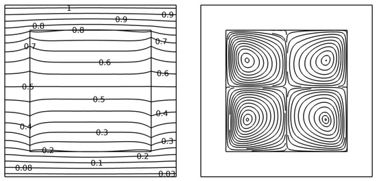
Figure 14.
Streamlines and isothermals obtained when heating the top, Wmax = 2.6317.
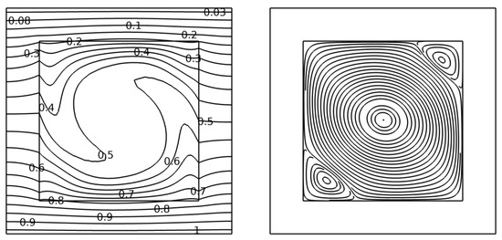
Figure 15.
Streamlines and isothermals obtained when heating the bottom, Wmax = 69.235.
5. Conclusions
Numerical calculations have been carried out on the combined heat transfer induced by thermal conduction, natural convection and surface radiation in the porous char layer that forms from intumescent coating under fire. The isothermals, streamlines and average Nusselt number are obtained at different parameters as follows: the Rayleigh number (Ra), conductivity ratio (Kr), emissivity (ε), radiation–conduction number (Nr), void fraction (ϕ) and heating mode. The following conclusions could be drawn:
- The Rayleigh number and the conductivity ratio have a positive effect on natural convection. As Ra increases, the air flow in the cavity is much stronger and the natural convection heat transfer is strengthened due to the increase in buoyancy force. The increase in the conductivity ratio results in an increase in the walls’ temperature difference. Then, natural convection, which is driven by the temperature difference, is strengthened. In addition, the effect of Kr on the heat transfer always has a limit when it reaches a high level.
- The emissivity and radiation–conduction number have a significant effect on the total heat transfer when the temperature ratio is a constant. With increasing ε and Nr, surface radiation is enhanced. This leads to a decrease in the walls’ temperature difference, which will certainly inhabit natural convection in the cavity. In addition, Nr plays a more important role in a certain range, and the impact on the heat transfer will be limited when Nr is too low or too high.
- The void fraction of the structure also affects the total heat transfer. The change in ϕ will cause a change of both the temperature difference and characteristic length. Natural convection and surface radiation are strengthened by the combined effect of temperature difference and characteristic length with the increasing void fraction.
- The heating mode has a remarkable effect on the total heat transfer. Proper use of the heating mode (which means the proper direction of the heat flow in this study) is able to cause stronger air flows. As a result, natural convection in the cavity will be strengthened but surface radiation among the walls will, as a result, be suppressed.
Author Contributions
Conceptualization, Y.H. and M.L.; methodology, L.Z.; software, L.Z.; validation, Y.H., L.Z., and M.L.; formal analysis, L.Z.; investigation, Y.H.; resources, Y.H.; data curation, L.Z.; writing—original draft preparation, L.Z.; writing—review and editing, L.Z.; visualization, L.Z.; supervision, Y.H.; project administration, M.L.; funding acquisition administration, M.L. All authors have read and agreed to the published version of the manuscript.
Funding
This research was funded by National Nature Science Foundation of China, Grant No. [51706213].
Institutional Review Board Statement
Not applicable.
Informed Consent Statement
Not applicable.
Data Availability Statement
Not applicable.
Conflicts of Interest
The authors declare no conflict of interest.
Nomenclature
| Fsk-sj | view factor between surface k and j |
| G | temperature ratio (Th/Tc) |
| Nu | local Nusselt number |
| J | dimensionless radiosity |
| k | thermal conductivity |
| kr | solid to air conductivity ratio |
| L | length of the structure |
| l | length of the cavity |
| Nr | radiation to conduction number |
| P | dimensionless pressure |
| Pr | Prandtl number (νf/αf) |
| Q | dimensionless net radiative heat flux |
| q | net radiative heat flux |
| Ra | Rayleigh number |
| T | absolute temperature (K) |
| (u, v) | velocity (m/s) |
| (U, V) | dimensionless velocity |
| W | W2 = U2 + V2 |
| (x, y) | Cartesian coordinates |
| (X, Y) | dimensionless Cartesian coordinates |
| Greek Symbols | |
| α | thermal diffusivity (m2/s) |
| β | thermal expansion coefficient (K−1) |
| ε | emissivity of the interface |
| ρ | density (Kg/m3) |
| σ | Stephan–Boltzmann constant |
| ϕ | void fraction of the structure |
| ν | kinematic viscosity (m2/s) |
| θ | dimensionless temperature |
| Subscripts | |
| conv | convection |
| f | air |
| j.k | jth and kth subdivisions |
| rad | radiation |
| s | solid |
| t | total |
| h, c | hot and cold |
References
- Mariappan, T. Recent developments of intumescent fire protection coatings for structural steel: A review. J. Fire Sci. 2016, 34, 120–163. [Google Scholar] [CrossRef]
- Yasir, M.; Ahmad, F.; Yusoff, P.S.M.M.; Ullah, S.; Jimenez, M. Latest trends for structural steel protection by using intumescent fire protective coatings: A review. Surf. Eng. 2019, 36, 334–363. [Google Scholar] [CrossRef]
- Chuang, Y.J.; Chuang, Y.H.; Lin, C.Y. Fire tests to study heat insulation scenario of galvanized rolling shutters sprayed with intumescent coatings. Mater. Des. 2009, 30, 2576–2583. [Google Scholar] [CrossRef]
- Reshetnikov, I.; Antonov, A.; Rudakova, T.; Aleksjuk, G.; Khalturinskij, N.A. Some aspects of intumescent fire retardant systems. Polym. Degrad. Stab. 1996, 54, 137–141. [Google Scholar] [CrossRef]
- Reshetnikov, I.; Yablokova, M.Y.; Potapova, E.; Khalturinskij, N.A.; Chernyh, V.Y.; Mashlyakovskii, L.N. Mechanical stability of intumescent chars. J. Appl. Polym. Sci. 1998, 67, 1827–1830. [Google Scholar] [CrossRef]
- Reshetnikov, I.; Garashchenko, A.; Strakhov, V. Experimental investigation into mechanical destruction of intumescent chars. Polym. Adv. Technol. 2000, 11, 392–397. [Google Scholar] [CrossRef]
- Gottfried, S. Intumescent Fire-Retardant Composition for High Temperature and Long Duration Protection. U.S. Patent 5,723,515, 3 March 1998. [Google Scholar]
- Jimenez, M.; Duquesne, S.; Bourbigot, S. Characterization of the performance of an intumescent fire protective coating. Surf. Coat. Technol. 2006, 201, 979–987. [Google Scholar] [CrossRef]
- Wang, Z.; Han, E.; Ke, W. Influence of expandable graphite on fire resistance and water resistance of flame-retardant coatings. Corros. Sci. 2007, 49, 2237–2253. [Google Scholar] [CrossRef]
- Koo, J.; Pilato, L. Thermal Properties and Microstructures of Polymer Nanostructured Materials. In Nanoengineering of Structural, Functional and Smart Materials; Schulz, M.J., Ed.; CRC: Boca Raton, FL, USA, 2005. [Google Scholar]
- Camino, G.; Fina, A. New perspectives in fire retardant coatings. Pitture E Vernic. Eur. Coat. 2008, 7, 1–6. [Google Scholar]
- Cagliostro, D.E.; Riccitiello, S.R.; Clark, K.J.; Shimizu, A.B. Intumescent coating modeling. J. Fire Flammabl. 1975, 6, 205–221. [Google Scholar]
- Anderson, C.E.; Dziuk, J.; Mallow, W.A.; Buckmaster, J. Intumescent reaction mechanisms. J. Fire Sci. 1985, 3, 161–194. [Google Scholar] [CrossRef]
- Buckmaster, J.; Anderson, C.; Nachman, A. A model for intumescent paints. Int. J. Eng. Sci. 1986, 24, 263–276. [Google Scholar] [CrossRef]
- Butler, K.M.; Baum, H.R.; Kashiwagi, T. Three-dimensional modeling of intumescent behavior in fires. Fire Saf. Sci. 1997, 5, 523–534. [Google Scholar] [CrossRef][Green Version]
- Blasi, C.D.; Branca, C. Mathematical model for the nonsteady decomposition of intumescent coatings. AIChE J. 2001, 47, 2359–2370. [Google Scholar] [CrossRef]
- Blasi, C.D. Modeling the effects of high radiative heat fluxes on intumescent material decomposition. J. Anal. Appl. Pyrolysis 2004, 71, 721–737. [Google Scholar] [CrossRef]
- Zhang, Y.; Wang, Y.C.; Bailey, C.; Taylor, A.P. Global modelling of fire protection performance of intumescent coating under different cone calorimeter heating conditions. Fire Saf. J. 2012, 50, 51–62. [Google Scholar] [CrossRef]
- Zhang, Y.; Wang, Y.C.; Bailey, C.G.; Taylor, A.P. Global modelling of fire protection performance of an intumescent coating under different furnace fire conditions. J. Fire Sci. 2013, 31, 51–72. [Google Scholar] [CrossRef]
- Yuan, J.F. Intumescent Coating Performance on Steel Structures under Realistic Fire Conditions; Manchester Univ. Press: Manchester, UK, 2009. [Google Scholar]
- Yuan, J.F.; Wang, Y.C. Efficient modelling of temperatures in steel plates protected by intumescent coating in fire. In Fire Retardancy of Polymers: New Strategies and Mechanisms; Hull, T.R., Kandola, B.K., Eds.; RSC: Cambridge, UK, 2009. [Google Scholar]
- Staggs, J.E.J.; Crewe, R.J.; Butler, R. A theoretical and experimental investigation of intumescent behavior in protective coatings for structural steel. Chem. Eng. Sci. 2012, 71, 239–251. [Google Scholar] [CrossRef]
- Cirpici, B.K.; Wang, Y.C.; Rogers, B. Assessment of the thermal conductivity of intumescent coatings in fire. Fire Saf. J. 2016, 81, 74–84. [Google Scholar] [CrossRef]
- Cirpici, B.K.; Wang, Y.C.; Rogers, B.D.; Bourbigot, S. A theoretical model for quantifying expansion of intumescent coating under different heating conditions. Polym. Eng. Sci. 2016, 56, 798–809. [Google Scholar] [CrossRef]
- Amon, M.; Denson, C.D. A study of the dynamics of foam growth: Analysis of the growth of closely spaced spherical bubbles. Polym. Eng. Sci. 2010, 24, 1026–1034. [Google Scholar] [CrossRef]
- Bartholmai, M.; Schriever, R.; Schartel, B. Influence of external heat flux and coating thickness on the thermal insulation properties of two different intumescent coatings using cone calorimeter and numerical analysis. Fire Mater. 2003, 27, 151–162. [Google Scholar] [CrossRef]
- Staggs, J.E.J. Thermal conductivity estimates of intumescent chars by direct numerical simulation. Fire Saf. J. 2010, 45, 228–237. [Google Scholar] [CrossRef]
- Li, G.-Q.; Han, J.; Lou, G.-B.; Wang, Y.C. Predicting intumescent coating protected steel temperature in fire using constant thermal conductivity. Thin-Walled Struct. 2016, 98, 177–184. [Google Scholar] [CrossRef]
- Jamal, B.; Boukendil, M.; Abdelbaki, A.; Zrikem, Z. Numerical simulation of coupled heat transfer through double solid walls separated by an air layer. Int. J. Therm. Sci. 2020, 156, 106461. [Google Scholar] [CrossRef]
- Yang, G.; Wu, J.Y. Effect of natural convection, wall thermal conduction, and thermal radiation on heat transfer uniformity at a heated plate located at the bottom of a three-dimensional rectangular enclosure. Numer. Heat Transf. Part A Appl. 2016, 69, 589–606. [Google Scholar] [CrossRef]
- Kang, S.; Choi, J.; Choi, S. Mechanism of heat transfer through porous media of inorganic intumescent coating in cone calorimeter testing. Polymers 2019, 11, 221. [Google Scholar] [CrossRef] [PubMed]
- Barak, G.; Mitsoulis, E.; Assimacopoulos, D. Natural convection flow in a square cavity revisited: Laminar and turbulent models with wall functions. Int. J. Numer. Methods Fluids 2010, 18, 695–719. [Google Scholar] [CrossRef]
Publisher’s Note: MDPI stays neutral with regard to jurisdictional claims in published maps and institutional affiliations. |
© 2021 by the authors. Licensee MDPI, Basel, Switzerland. This article is an open access article distributed under the terms and conditions of the Creative Commons Attribution (CC BY) license (http://creativecommons.org/licenses/by/4.0/).