Article

Defect Analysis of 316 L Stainless Steel Prepared by LPBF Additive Manufacturing Processes

School of Mechanical and Automotive Engineering, South China University of Technology, Guangzhou 510640, China
*
Author to whom correspondence should be addressed.
Coatings 2021, 11(12), 1562; https://doi.org/10.3390/coatings11121562
Submission received: 30 October 2021 / Revised: 29 November 2021 / Accepted: 15 December 2021 / Published: 19 December 2021

Abstract

:
The 316 L stainless-steel samples were prepared by laser powder bed fusion (LPBF). The effects of processing parameters on the density and defects of 316 L stainless steel were studied through an orthogonal experiment. The density of the samples was measured by the Archimedes method, optical microscopy (OM) and X-ray Computed Tomography (XCT). The microstructures and defects under different LPBF parameters were studied by OM and SEM. The results show that the energy density has a significant effect on the defect and density of the structure. When the energy density is lower than 35.19 J/mm3, the density increases significantly with the increase of energy density. However, when the energy density is larger than this value, the density remains relatively stable. The process parameter with the greatest influence on energy density is the hatch distance D, followed by laser power P, scanning speed V and rotation angle θ. In this paper, the optimum parameters consist of P = 260 W, V = 1700 mm, D = 0.05 mm and θ = 67°, in which the density is as high as 98.5%. In addition, the possibility and accuracy of the XCT method in detecting the discontinuity and porosity of 316 L stainless steel were discussed. The results show that XCT can provide the whole size and variation trend of pores in the different producing direction of LPBF.

1. Introduction

Additive manufacturing (AM) [1,2] is a technology that allows physical components to be fabricated via the layer-by-layer addition of materials. It has been widely used to fabricate various components and structures for the different applications [3,4,5]. Compared with the conventional subtractive manufacturing technology, AM technology can significantly reduce the processing procedures and shortens the processing cycle [6], as well as enabling the fabrication of complex structural components.
Laser powder bed fusion (LPBF) is one of the AM processes. Currently, LPBF process can manufacture metal parts with different material powders, such as titanium alloy [7,8], nickel base superalloy [9,10], aluminum alloy [11,12], stainless steel [13,14] and so on.
It is reported [15] that the metal parts produced by LPBF account for 82% of the total powder bed molten parts. However, LPBF technology still has some limitations, such as the limited types of metals that can be used for printing, the low printing efficiency, and especially the structural defects in printed parts, which in turn limits the application of LPBF [16,17,18,19]. LPBF is a complex process [20] due to some factors such as that the rapid movement of laser with high energy density leads to the rapid melting and rapid cooling of metal, and each layer of metal will be subjected to a periodic thermal cycle. These characteristics of LPBF process have a significant impact on structural defects in the parts printed [21]. The microstructure defects mainly include porosities, incomplete gas porosity, lack-of-fusion, keyholes, balling phenomena and so on. These defects possess different characteristics. The characteristics of gas porosities are ball shape, in a small size of tens micrometer, uniform distribution in the specimen. However, for the lack-of-fusion, the shape often is irregular and the size is in hundreds micrometer, and they usually appear at surface and interior layers. Keyhole is associated with deep and narrow vapor depressions, which occur under high-power, low-scan speed laser melting conditions. Balling characteristics is highly coarsened balls possessing an interrupted dendritic structure in the surface layer of balls. In according to the previous reports, the causes of forming these defects in the specimens by LPBF can be divided into two categories. Some defects, mainly gas porosity, are caused by the raw materials, which cannot be usually eliminated by optimizing process parameters. Other defects, mainly lack-of-fusion and keyhole, balling phenomena, and so on, are caused by the process parameters or equipment, which can be reduced or eliminated by optimizing process parameters in the oxygen content, scanning rate, fluidity and wettability of molten metal in micro-pool, etc. Thus, it is important to optimize the process parameters for LPBF.
However, there is no standard definition of the optimal parameter range for LPBF. The optimal process parameters are different for the different materials. For example, the porosity first increases and then decreases in an as-synthesized Ti6Al4V alloy over a scan speed of 1500–4500 mm/s [22,23], while a simple reduction trend in porosity was found with scan speed increasing in the range of 500–1200 mm/s [24,25]. Moreover, the case is different for the Invar 36 samples, which show very low porosity (<0.5%) when the laser scanning speeds are below 3200 mm/s, but remarkably increased porosity above 3200 mm/s (at 400 W) [26]. It is observed that the distribution law and formation mechanism of microstructure defects in LPBF alloys have not been fully clarified, and no unified conclusion has been established regarding the effects of process parameters on relative density and defects [27]. Muhannad [28] found that despite the same set process parameters, there is significant variations were found in the mechanical performance and properties of the AM samples produced on the different L-PBF metal additive manufacturing machines. Germán [29] used numerical simulation method to predict the lowest degree of porosity is obtained with high laser power, low scanning speed, and the lowest hatch spacing with a recommendable volumetric energy density greater than 60 J/mm3. They found that the importance of the hatch spacing is highlighted since if the same laser power and scan speed are used, but with different hatch spacings, a high degree of porosity can be obtained if the correct size of the molten pool is not ensured. Chawla and Deng [30] performed a study to systematically describe the effect porosities on mechanical properties of sintered Fe-0.85Mo-Ni steel parts. It is reported that porosity in sintered parts reduces the load bearing cross-sectional area of the part, acts as a stress concentration, and significantly affects fatigue behavior.
The analysis methods for detecting the microstructural defects in LPBF parts are critical to explore the optimal process parameters. Currently, the most widely used porosity analysis methods include the metallographic method and Archimedes method. However, the former is time-consuming and destructive, and its detecting accuracy is usually affected by the metallographic section and the magnification of the cutting surface. The latter can determine the relative density of samples without destructing sample, but it cannot provide the information about the shape and location of pores in materials. X-ray Computed Tomography (XCT) is a non-destructive test method that provides information regarding the spatial distribution of micro-defects in the analyzed structures, which is based on a cone-beam geometry [31]. XCT is an important and powerful method for the analysis of the internal structure of materials, allowing the visualization and evaluation of pores, cracks, inclusions, or defects in materials [32,33,34]. For example, XCT is applied to investigate the effect of geometry and defects in titanium components prepared by AM [35], as well as to perform density measurements of metallic components [36].
In this study, 316 L stainless steel was prepared by LPBF to study the forming causes and distribution law of defects with processing conditions. Taguchi experiment was mainly used to investigate the influences of process parameters on defects and find the optimal parameters to obtain the high-density specimens. The relative density of the printed samples was estimated by OM, Archimedes and XCT methods, respectively. Finally, the information regarding the spatial structure of defects in the printed samples provided by the XCT is used to determine the effect of building strategy on porosity. In this regard, the reconstructed volumes are oriented in space in relation to the built platform. Space registration corresponding to the actual positioning of specimens in the LPBF chamber allows the spatial distribution of porosity in the test samples to be visualized and evaluated.

2. Materials and Methods
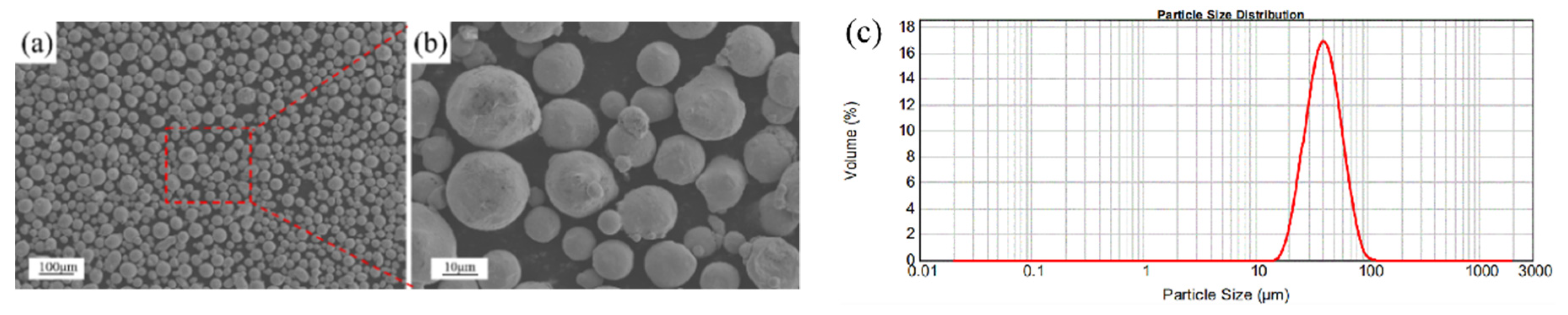
2.1. Material

The oxides formed in LPBF adversely affect the properties of the fabricated components [37]. The oxygen content of water-atomized powder is higher than that of gas-atomized powder. Therefore, gas-atomized 316 L stainless steel powder with an approximately spherical shape was used in this study. The composition of 316 L stainless steel formed by LPBF was determined by electric spark vacuum emission and is listed in Table 1. The morphology of the powder is shown in Figure 1a; on the surface of the powder, small satellite spherical powder particles are present (as shown in Figure 1b), and the particle size is shown in Figure 1c. The spherical particles have a size distribution between 25.97 μm (D10) and 63.34 μm (D90) with a volume diameter of approximately 40.48 μm.

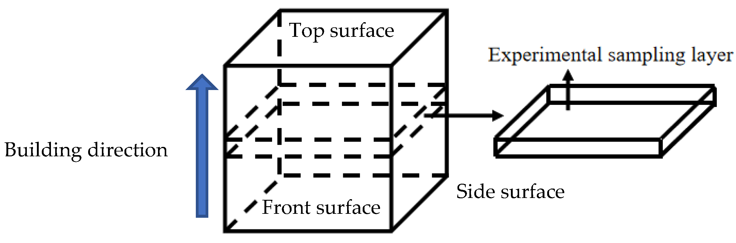
2.2. Experimental Method

Metallic components were fabricated via LPBF using the EOSM290 equipment Gmbh (EOS, Munich, Germary), where Nd: YAG laser with a maximum power of 400 W and a laser scanning speed of 7000 mm/s were applied. The entire forming process was performed in an environment containing nitrogen. Various parameters can be varied to change the components, including material-specific parameters, laser parameters, scan parameters, the scanning speed, and the rotation angle.
Energy density is typically used to describe the average applied energy per volume of a material during powder bed fusions. For LPBF, it can be expressed as show in Equation (1) below [38]:
E = P V · h · t
where P is the laser power; V the scan speed; h is the hatch spacing; t is the layer thickness. In the present paper, the relationship between energy density and surface roughness and relative density will be discussed.
The Taguchi experiment (L9) was conducted to investigate the significance of each factor. The factors and levels for the Taguchi experiment are shown in Table 2 at a layer thickness of 40 μm. The Taguchi experiment is applied to analysis the relationship between the porosity and energy density in the samples prepared by LPBF [39,40]. The experimental factors and their levels are listed in Table 2. The processing conditions are presented comprehensively in Table 2.
The relative densities of the samples were determined using the Archimedes method based on ASTM B962-08 by BSA224S [41]. The samples were treated by ultrasonic cleaning for 5 min in propanol and distilled water. Subsequently, the measured density was compared with the nominal value of 316 L stainless steel to estimate the porosity using Equation (2) [42].
R D = 1 ρ r ρ n
where R D is the porosity, ρ r the relative density, and ρ n the nominal density. The equation shows that the lower the measured density   ρ r , the higher is the porosity. The measurement precision was improved by averaging the measured values of the repeated measurements.
First, all samples were extracted using wire cutting equipment (Cmne, Beijing, China) from regions greater than 5 mm from the built surfaces to avoid sampling chemical or structural inhomogeneities associated with the initial or final layers. The thickness of one section is about 2 mm. The sampling area of this experiment is shown in Figure 2.
Subsequently, and standard metallographic specimens were prepared using a metallographic inlay machine (XQ-2B, Wuhan, China). The cross-sections of the samples were ground using 180–2000 grit sandpapers and polished using a rotary polisher. To reveal the microstructure, the polished samples were etched using Kroll’s reagent for 1–2 min, followed by treatment with 10 mL of HF, 5 mL of HNO3, and 100 mL of H2O.
The surface roughness was measured on the top and front and side surface of the as-received samples using the surface profilometer(VR-500, Kuala Lumpur, Malaysia), respectively. The roughness value of each surface is taken as the average value after surface scanning for 10 times. The optical images of the polished surface and the microstructure topography were obtained using a digital microscope (Leica DML 5000, Munich, Germary) and a scanning electron microscope (SEM, Zeiss SUPRA 40, Munich, Germary) equipped with an energy dispersive spectrometer, respectively.
The 316 L specimens were scanned to obtain the pore morphology and evolution trend of the porosity using a Phoenix vltomelx machine.(L300 CT, San Francisco, America) The system was equipped with a 225 kV X-ray source with a minimum focal spot size of 5 µm and a Perkin Elmer. During scanning, the X-ray beam was filtered using a 0.25 mm Cu filter to reduce beam-hardening effects. The parameters were selected based on the density and size of the tested samples. The scanning parameters are presented in Table 3. Avizo software is used to post process the data obtained from XCT to visualize the porosity of different observation surfaces.

3. Results and Discussion

The amount and morphology of porosity defects were evaluated based on the process parameters used to prepare the samples. According to the metallographic structure at different energy densities observed porosity morphology and surface characteristics, the mechanism of defect generation is discussed.

3.1. Surface Roughness and Melting Track

It has been reported that the surface quality of components fabricated via LPBF is inferior [11]. Surface roughness is a function of the powder particle size and applied laser energy; it indicates whether complete melting or partial sintering can occur [3,8].
In the nine cubic specimens prepared by LPBF (20 mm × 20 mm × 20 mm) based on the Taguchi experiment (L9), no obvious defects appear in blocks 1, 2, 4, 5, 6, 7, 8 and 9, with fine particles on the top surface. Scanning tracks with rotation angle of 67° can also be observed on the tops of blocks 2, 6 and 7. The top of square 3 contains obvious uneven holes. The side surfaces are smoother than the top surfaces for all samples. It was preliminarily determined that the density of the no.3 sample was lower than that of other samples.
Figure 3 shows the relationship between sample roughness and laser energy density in three different directions. As shown, the samples fabricated at a low laser energy density exhibited roughness in a high-level range of 20–40 μm in area 1 (the blue dashed block in Figure 3). As the energy density increased, the surface roughness in the three directions decreased gradually. When the laser energy was directed toward area 2 (the red dashed block in Figure 3), the minimum roughness value that was achieved was approximately 5 μm and corresponds to 6# process parameters: laser power P, 260 W; scanning speed V, 1700 mm/s; hatch spacing D, 0.05 mm; rotation angle θ, 67°; layer thickness, 0.04 mm. With further increasing energy density to area 3 (the yellow dashed block in Figure 3), however, the surface roughness of the sample becomes larger than one in the area 2, but lower than the area 1. However, the dimensional accuracy of the samples in area 3 was worse than that in area 2.
In addition, for the samples under the same process parameters, the roughness of the top surface was greater than that of the other two side surfaces. In terms of the side surfaces, the morphology observed therein was much smoother than that at the top surface. It is noteworthy that the side surfaces present repetitive layer melting, in which the powder is subjected to several phases of laser energy during the formation of successive layers. The lower layers receive additional heat during the successive formation of layers above. This is because LPBF involves gradual melting and powder solidification from bottom to top. For the front and side materials, each layer of metal powder is melted layer by layer.
Figure 4 shows the top surface features of the scanning tracks fabricated by LPBF under different energy density. It was clear that the surface structures varied with the melting tracks. When the laser energy density was the lowest (18.63 J/mm3) for the sample 3, the surface topography contained a significant amount of powders that were not completely melted, which contributed primarily to the high surface roughness in Figure 4c. When the energy density of sample 2 increased to 35.19 J/mm3, the unfused powder particles on the surface decreased significantly but some pores still remained as in Figure 4b, and sample 5 (32.10 J/mm3) indicated a striped track in Figure 4e. The surface roughness of samples 1, 7 and 9 decreased owing to the splashing powder as shown in Figure 4a,g,i.
When the energy density was 65.00 J/mm3, the surface shows a smooth melting track and semi-continuous melting track at 76.47 J/mm3. When the energy density of sample 8 increased to 122.22 J/mm3, the surface roughness began to increase again with the increase of powder balling phenomena and agglomeration. Hence, the parameters for the lowest surface roughness were as follows: laser power P, 260 W; scanning speed V, 1700 mm/s; hatch spacing D, 0.05 mm; rotation angle θ, 67°; layer thickness, 0.04 mm, corresponding to the energy density 76.47 J/mm3.

3.2. Relative Density Regularity with Processing Parameters

The relative densities of the Taguchi experiment samples measured using the Archimedes method are shown in Table 4. The relationship between the laser energy density and the relative density of the samples is shown in Figure 5.
As shown in Figure 5, when the energy density was 18.63–150.00 J/mm3, the change rule of the relative density with the energy density can be classified into four ranges: (i) the relative density increases significantly with the energy density, i.e., the density 75.79% of sample 3 is increased to 95.91% of sample 5 when the energy density increased from 18.63 J/mm3 to 32.10 J/mm3, respectively; (ii) the relative density increases gradually with the energy density from 32.10 J/mm3 (sample 5) to 76.47 J/mm3 (sample 6), also including 35.19 J/mm3 (sample 2), 48.53 J/mm3 (sample 9) and 55.00 J/mm3 (sample 7) in this range; (iii) the relative density is increased to the highest level about 98%, as the energy density is fallen into the range from 65.00 J/mm3 (sample 6) to 76.47 J/mm3 (sample 4). As well, the relative densities are basically stable with the increasing of energy density in this range; (iv) when the laser energy density was furtherly increased to 95.00 J/mm3 (sample 1) to 122.22 J/mm3 (sample 8), the relative density of 316 L stainless steel is slightly decreased to about 97%, indicating that an optimal range of energy density value is within a certain range. Previous studies have shown that when the relative density of 316 L stainless steel prepared by LPBF is lower than 95.00% [25], the mechanical properties of the components are significantly affected, and the tensile strength, yield strength and elongation are reduced, resulting in premature failure during service. Hence, it can be concluded that: (1) A critical value for the energy density exists, is 32.10 J/mm3, which corresponds to sample 5. When the energy density was lower than this value, the densities were less than 95%. (2) When the energy density was extremely higher than 95.00 J/mm3, the relative density decreased. Therefore, the optimal range of energy density is from 32.10 J/mm3 to 95.00 J/mm3 in this paper. However, this case is different from the result of the literature [43], in which the optimal energy density is from 112.50 J/ mm3 to 150.00 J/ mm3. This may be resulted from the different printing equipment and the properties of raw powder.
The effects of four processing parameters including laser power, scanning speed, hatch spacing, and rotation angle on the relative density are shown in Table 5 and Figure 6 using the Taguchi experiment. The affecting order of the four process parameters is the hatch distance D with the greatest degree, followed by laser power P, scanning speed V and rotation angle θ. When the laser power was between 190 and 260 W, the relative density of the sample increased significantly with the laser power and reached a maximum value at 260 W, whereas it decreased slightly between 260 and 330 W. In contrast to the case when the scanning speed was 1000–1700 mm/s, the relative density of the samples continued to decrease. In particular, a faster scanning speed resulted in an insufficient melting of powder; hence, the relative density declined rapidly between 1350 and 1700 mm/s. Owing to the increase in the scanning speed, the hatch spacing increased from 0.05 to 0.1 mm, and the relative density decreased slowly. However, as the hatch spacing increased from 0.1 to 0.15 mm, the large hatch spacing rendered it impossible for liquid powder to lap well; therefore, the relative density decreased significantly. However, when the rotation angle increased from 0° to 67°, the relative density increased slowly and reached a maximum value at 67°. As the rotation angle increased from 67°to 90°, the density decreased significantly. Hence, it can be observed that the optimal process parameters for highest relative density are same as those for surface roughness mentioned above. In other word, the good surface roughness corresponds to high relative density. However, this case is not always sure. For example, the two sets of process parameters are different in the study of Chen [44], in which the optimum parameters for relative density were as follows: laser power P, 95 W; scanning speed V, 450 mm/s; hatch spacing D, 0.08 mm, while the optimum one for surface roughness were as follows: laser power P, 85 W; scanning speed V, 500 mm/s; hatch spacing D, 0.09 mm. This difference is relational to the kind of material.

3.3. Porosity

Metallographic observations were performed on the XOY plane from the middle height of the printing direction of samples 1–9. The two most influential parameters-the hatch spacing D and laser power P, were set as the horizontal and vertical coordinates for classification, as shown in Figure 7. It can be partitioned into four regions, as follows:
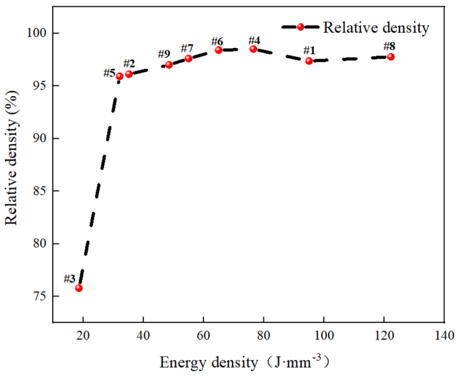
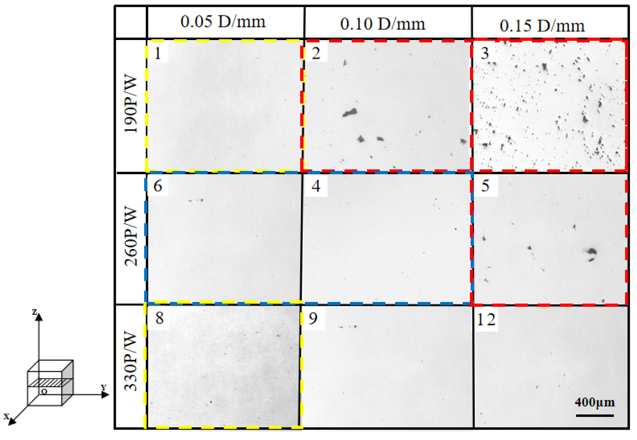
  • The upper right corner area indicated by the red dotted box in Figure 7, contains samples 2, 3 and 5. This region corresponds to a large hatch spacing, low laser power, and low energy density. The low energy density resulted in a significant amount of unfused powder and hence the formation of pores, particularly for samples 3. However, for these three samples, the factors contributing to the formation of low-compactness pores were different. For sample 3, the factors were the low laser power and large hatch spacing. For sample 2 and 5, the corresponding the less laser power was 190 W and 260 W, respectively, and a relatively high scanning speed (1350 mm/s), which afforded a low relative density. The pores in samples 2 and 5 in this area were less than those in samples 3.
  • The lower right corner areas, which included samples 7 and 9. This region corresponds to a high laser power, large hatch spacing, and moderate energy density. The relative density of these samples increased with the energy density, and the relative density exceeded 97%.
  • The middle region indicated by the blue dotted box in Figure 8, corresponds to a medium laser power, small hatch spacing, and medium energy density, and indicates the relative density which higher than 98%.
  • The upper left and lower left areas indicated by the yellow box in Figure 7, corresponding to sample 1 and 8, respectively. These two regions have a high energy density, but the factors contributing to the high energy density are different. For sample 8, the high energy density was primarily contributed by the high laser power and low hatch spacing. For sample 1, a low hatch spacing and a low scanning speed would result in a high energy density. The compactness of this region was similar to that of the lower-right corner. However, the relative density of this region decreased as the energy density increased.

3.4. Microstructural Development

Based on the analysis above, it was clear that when the energy density was extremely high, the relative density decreased. The reason for this is further discussed herein based on the metallographic structure after corrosion, as shown in Figure 8.
The metallographic structure diagrams of the four samples including sample 3 (18.63 J/mm3), sample 2 (35.19 J/mm3), sample 4 (65.00 J/mm3) and sample 8 (122.22 J/mm3) are presented in Figure 9. For sample 3 (Figure 8a) with the low relative density, the surface structure was loose and contained numerous pores, the largest size of which exceeded 100 µm. For sample 2 (Figure 8b), the microstructure of some micro-melting pools can be seen obviously, but certain pores can be present locally due to the relative low energy density of 35.19 J/mm3. Sample 4 (Figure 8c) contained primarily cone-like solidified melt pools at elevated energy density of 65 J/mm3; therefore, pores were almost invisible here. For sample 8 (Figure 8d) with a higher energy density, the metallographic structure differed significantly from that of sample 4. Numerous corrosion trenches appeared in the micro-melting pool, which was likely to be caused by over-melting due to the heat input. The grain size of the over-melted section was extremely large, and the corrosion resistance decreased; therefore, the groove morphology appeared after corrosion.
Based on the optical microscope (OM) analysis above, the morphologies of the three typical defects shown in the SEM images are presented in Figure 9. The numerous lapping defects were observed in sample 3 (Figure 9a). At the larger magnification (Figure 8b), it was observed that numerous unfused powder particles were present owing to insufficient energy, which consequently resulted in the inferior wettability of the metal bath. Additionally, the metal could not flow easily in these local areas, thereby resulting in a non-filled partial gap in the bath. Meanwhile, the energy density of sample 2 was higher than that of sample 3, which enabled the melting of unfused powder particles. However, some unfused holes due to insufficiently filled molten metals are present under this energy level, for example sample 2 (Figure 9c,d). Furthermore, it was not only limited to the surface of the solidified metal, but was also embedded between the multiple layers of the solidified molten pool, showing an obvious lack of flesh. The inner surface was smooth without powder particles. The width and depth of the unfused defect increased significantly if the molten metal was not filled enough. This implies that the penetration depth of the laser energy in this region was low, and that the powder particles did not possess sufficient energy to melt and solidify to ensure sufficient bonding between the two layers. For sample 4, its defect was spherical and did not exceed 10 μm (Figure 9e,f). This is because the energy density at that time was optimal; therefore, the defects generated were much smaller than those of other samples.
To investigate the distribution space characteristics of the pores under an intermediate energy density (32.10 J/mm3), sample 2 was selected for industrial XCT detection. The analysis is presented in the following section.

3.5. XCT Detection of Internal Pores

As shown in Figure 5 above, the changing trend of density in the energy density range (ii) is relative stable, corresponding to the samples including sample 5, sample 2, sample 9, sample 7 and sample 6. In order to further investigate the distribution trend of pores in the sample by LPBF in this section, sample 2 was selected as the observed object by using XCT. To obtain the maximum resolution of the measurement, only a quarter (10 × 10 × 20 mm3) (length × width × high) of sample 2 was reconstructed (dashed red rectangle area in Figure 10.
The three-dimensional details of the internal pores in the as-received sample, including porosity, shape and spatial location of the pores, were characterized using the XCT technique. The results are presented in Figure 11.
Figure 11a–c represents the top, middle and bottom layer in XOY, respectively. As shown, the top and bottom layers contain more holes than the middle layer. This is because the middle layer possessed heat transferred from both upper and lower layers, which results in a low quantity of pore defects. For the bottom layer, the amount of heat was insufficient for an effective bonding between the layers. The top layer differed from the bottom layer which was in contact with the nitrogen in the forming cavity; therefore, the amount of waste heat was insufficient for the metal liquid to fuse and solidify, and rapid cooling resulted in an increased number of pores.
Figure 11d–f represents at the back layer, middle layer and front layer in YOZ, respectively. Here, the front layer named the outmost layer of as-received sample in YOZ, the middle layer is 5 mm away from the front layer, and the back layer is 10 mm away from the front layer, namely the center layer of the as-received sample in YOZ. Figure 11d shows the back layer of the YOZ direction, which contains a few pores. Furthermore, Figure 11e shows the increase in the number of pores in the middle layer, and Figure 11f shows the front layer which contained the most pores. This is because there is not enough heat source on the side contacting the nitrogen layer to melt the powder particles
Similarly, Figure 11g–i represents the left, middle and right layer in ZOX directions, respectively. Here, the right layer named the outmost layer of as-received sample in ZOX, the middle layer is away 5 mm from the right layer, and the left layer is away 10 mm from the right layer, namely the center layer of the as-received sample in ZOX. The distributing rule of pore defects from left to right layer in Figure 11g–i is similar to that of from back to front layer in Figure 11d–f. The causes resulting in this distribution is analogous too.
The relative density along the Z-axis of sample 2 was selected for analysis, as shown in Figure 12. It was observed that the density along the Z-axis changed from low to high and then to low. The densities at the top and bottom of the Z-axis direction were relatively low, which is consistent with the XCT slice images in Figure 12a,c. The overall density was approximately 97%, which was slightly higher than that measured using the Archimedes method (Table 3).
To furtherly estimate the porosity of the specimens fabricated via LPBF and verify the XCT method presented herein, the comparative study of the density of sample 2 is made between XCT, metallographic method and Archimedes method. For the observation, a polished cross-section was prepared on a longitudinal section extending through the central part of sample 2 (along the Z-axis). Owing to the large size of the 316 L specimens, a series of images was combined using the stitching mode and then captured at a magnification ratio of 25×, which allowed the analysis of the entire area of the tested sample.
Metallographic method was performed using the two-dimensional (2D) image analysis software, “Image Pro Plus 6.0.” The recorded images were subjected to a binarization process, which allowed the relative contribution of pores on the surfaces of the investigated samples to be determined. Subsequently, using expressions that define Feret’s diameter, the total area of the examined objects (pores) was determined in 2D space, based on the analysis of the objects identified in the longitudinal plane. The comparison results between the XCT method and metallographic method were shown in Figure 13. A summary of the porosity for sample 2 using the three different methods is shown in Table 6.
From Table 6, the relative density of sample 2 was 96.12% by Archimedes method, whereas based on the metallographic method and XCT detection, the densities were 96.3% and 97%, respectively. It can be seen that the relative density is highest using XCT method. This discrepancy occurred because the XCT detection accuracy was affected by the system precision of the equipment and the image testing method. This result is also certified by Zi [45], in which the density measured by industrial CT method was 98.39%, while the density measured by metallography was 95.26%. Limitation of the XCT system is always present, which could not distinguish defects that were smaller than 5 µm. An example of the pore distribution in the cross-section of sample 2 after the binarization process obtained from the XCT analysis is presented in Figure 13. The comparison shows that sample 2 exhibited a low porosity because most of the small defects (pores) were uniformly distributed and therefore impossible to detect via the XCT method. The analysis of samples with small dimensions allows for the reconstruction of defects at a higher resolution.

4. Conclusions

In the present study, LPBF was used to prepare 316 L stainless-steel specimens using different printing parameters. The change rule of the density of the printed components with the energy density under different process parameters and the effects of the process parameters on the tissue defects were analyzed, and the following conclusions were obtained.
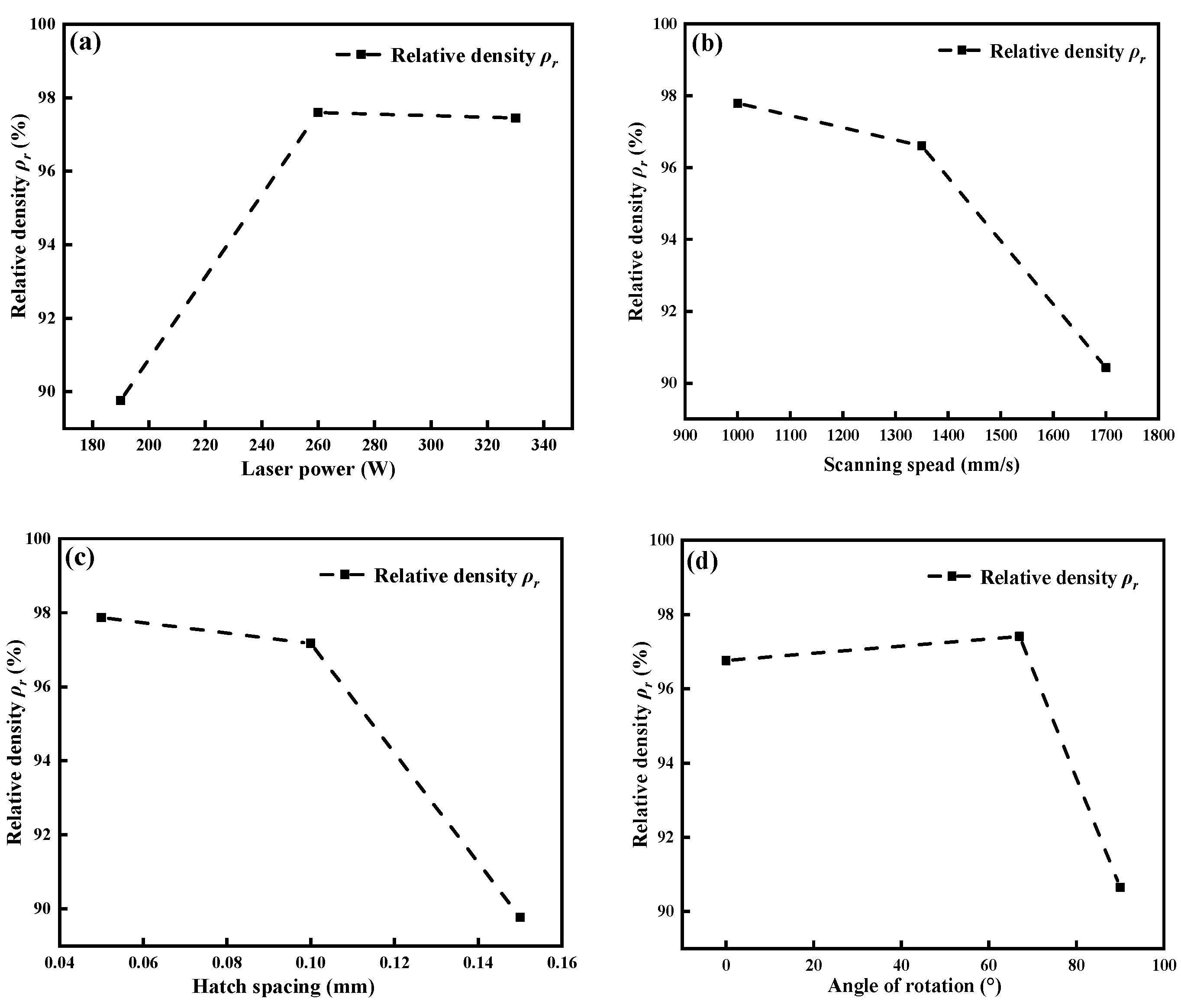
  • Laser power P, scanning speed V, hatch spacing D, and rotation angle θ significantly affected the density of the stainless-steel samples prepared via LPBF. The order of influence from high to low was hatch spacing larger than laser power larger than scanning speed larger than rotation angle.
  • In this study, the optimal density was 98.5%, and the corresponding process parameters were as follows: laser power, P = 260 W; scanning speed, V = 1700 mm/s; hatch spacing, D = 0.05 mm; rotation angle, θ = 67°; layer thickness, 0.04 mm. The energy density was 76.47 J/mm3.
  • The low energy density resulted in a significant amount of unfused powder and hence the formation of pores, which contributed primarily to the high porosity. The high energy density caused excessive melting, which contributed primarily to over-melting and hence a decrease in density.
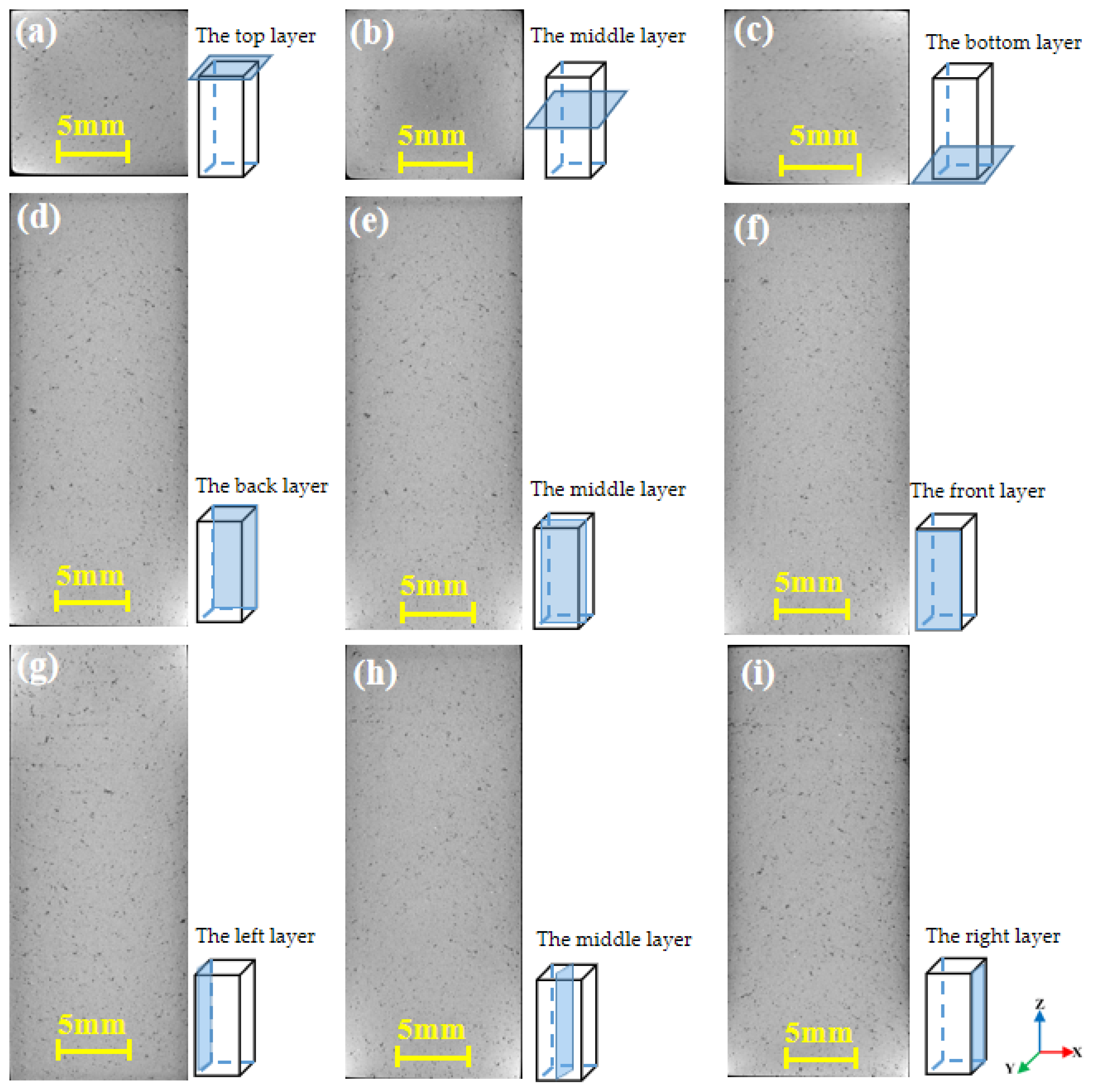
  • Based on the orthogonal test, one-quarter of sample 2 was selected for XCT detection. It was discovered that due to the melting of the central metal and the lack of re-melting of the surface metal, the density along the Z-axis changed from low to high and then to low.
  • The density of sample 2 based on different methods was as follows: 96.12% from Archimedes’ method; 96.30%, from metallographic method; 97.00% from XCT detection. The densities obtained from the latter two methods were higher than that from the Archimedes method; this is because the accuracy was affected by the system precision of the equipment.

Author Contributions

Conceptualization, Z.Z.; methodology, Z.Z. and L.P.; investigation, L.P.; data curation, L.P.; writingoriginal draft preparation, L.P.; writing-review and editing, Z.Z. and L.P.; supervision, Z.Z. and D.W.; project administration, Z.Z. All authors have read and agreed to the published version of the manuscript.

Funding

This research was funded by Natural Science Foundation of Guangdong Province, grant number 2021A1515010398”.

Institutional Review Board Statement

Not applicable.

Informed Consent Statement

Not applicable.

Data Availability Statement

Data sharing not applicable.

Conflicts of Interest

The authors declare no conflict of interest.

References

  1. Dadbakhsh, S.; Hao, L.; Sewell, N. Effect of selective laser melting layout on the quality of stainless steel parts. Rapid Prototyp. J. 2012, 18, 241–249. [Google Scholar] [CrossRef]
  2. Bermingham, M.; StJohn, D.; Krynen, J.; Tedman-Jones, S.; Dargusch, M. Promoting the columnar to equiaxed transition and grain refinement of titanium alloys during additive manufacturing. Acta Mater. 2019, 168, 261–274. [Google Scholar] [CrossRef]
  3. Ma, M.; Wang, Z.; Gao, M.; Zeng, X. Layer thickness dependence of performance in high-power selective laser melting of 1Cr18Ni9Ti stainless steel. J. Mater. Process. Technol. 2015, 215, 142–150. [Google Scholar] [CrossRef]
  4. Nguyen, Q.B.; Luu, D.N.; Nai, S.M.L.; Zhu, Z.; Chen, Z.; Wei, J. The role of powder layer thickness on the quality of SLM printed parts. Arch. Cio. Mech. Eng. 2018, 18, 948–955. [Google Scholar] [CrossRef]
  5. Carter, L.N.; Martin, C.; Withers, P.I.; Attallah, M.M. The influence of the laser scan strategy on grain structure and cracking behaviour in SLM powder-bed fabricated nickel superalloy. J. Alloys Compd. 2014, 615, 338–347. [Google Scholar] [CrossRef]
  6. Kong, D.; Ni, X.; Dong, C.; Lei, X.; Zhang, L.; Man, C.; Yao, J.; Cheng, X.; Li, X. Bio-functional and anti-corrosive 3D printing 316 L stainless steel fabricated by selective laser melting. J. Mater. Des. 2018, 125, 88–101. [Google Scholar] [CrossRef]
  7. Thijs, L.; Verhaeche, F.; Craechs, T.; Humbeeck, J.V.; Kruth, J.P. A study of the microstructural evolution during selective laser melting of Ti– 6Al–4V. J. Acta Mater. 2010, 58, 3303–3312. [Google Scholar] [CrossRef]
  8. Rafi, H.K.; Starr, T.L.; Stucker, B.E. A comparison of the tensile, fatigue, and fracture behavior of Ti-6Al-4V and 15-5 PH stainless steel parts made by selective laser melting. Int. J. Adv. Manuf. Technol. 2013, 69, 1299–1309. [Google Scholar] [CrossRef]
  9. Carter, L.N.; Attallah, M.M.; Reed, R.C. Laser powder bed fabrication of nickel-base superalloys: Influence of parameters; characterization, quantification and mitigation of cracking. Superalloys 2012, 795–802. [Google Scholar] [CrossRef]
  10. Jia, Q.B.; Gu, D.D. Selective laser melting additive manufacturing of Inconel 718 superalloy parts: Densification, microstructure and properties. J. Alloys Compd. 2014, 585, 713–721. [Google Scholar] [CrossRef]
  11. Gu, D.D.; Shen, Y.F. Research statues and technical of rapid manufacturing of metallic part by selective laser melting. J. Aeronaut. Manuf. Technol. 2012, 8, 32–37. [Google Scholar]
  12. Zhao, G.; Wang, D.D.; Bai, P.K.; Liu, B. Research progress of laser rapid prototyping technology for aluminum alloy. Hot Work. Technol. 2010, 39, 170–173. [Google Scholar]
  13. Li, R.; Liu, J.; Shi, Y.; Du, M.; Xie, Z. 316 L stainless steel with gradient porosity fabricated by selective laser melting. J. Mater. Eng. Perform. 2010, 19, 666–671. [Google Scholar] [CrossRef]
  14. Yadroitsev, I.; Gusarov, A.; Yadroitsava, I.; Smurov, I. Single track formation in selective laser melting of metal powders. J. Mater. Process. Technol. 2010, 210, 1624–1631. [Google Scholar] [CrossRef]
  15. Tapia, G.; Elwany, A. A Review on Process Monitoring and Control in Metal-Based Additive Manufacturing. J. Manuf. Sci. Eng. 2014, 136, 060801. [Google Scholar] [CrossRef]
  16. Gong, H.J.; Rafi, K.; Karthik, N.V.; Starr, T.; Stucker, B. Defect morphology of Ti-6Al-4V parts fabricated by selective laser melting and electron beam melting. In Proceedings of the 2013 International Solid Freeform Fabrication Symposium, Austin, TX, USA, 9–11 August 2013. [Google Scholar]
  17. Gu, D.D.; Hagedorn, Y.; Meiners, W.; Meng, G.R. PopraweDensifification behavior, microstructure evolution, and wear performance of selective laser melting processed commercially pure titanium. J. Acta. Mater. 2012, 60, 3849–3860. [Google Scholar] [CrossRef]
  18. Aboulkhair, N.T.; Everitt, N.; Ashcroft, I.; Tuck, C. Reducing porosity in AlSi10Mg parts processed by selective laser melting. Addit. Manuf. 2014, 1–4, 77–86. [Google Scholar] [CrossRef]
  19. Vilaro, T.; Colin, C.; Bartout, J.-D. As-Fabricated and Heat-Treated Microstructures of the Ti-6Al-4V Alloy Processed by Selective Laser Melting. Met. Mater. Trans. A 2011, 42, 3190–3199. [Google Scholar] [CrossRef]
  20. Lee, J.; Park, H.; Chai, S.; Kim, G.; Yong, H.; Bae, S.; Kwon, D. Review on Quality Control Methods in Metal Additive Manufacturing. Appl. Sci. 2021, 11, 1966. [Google Scholar] [CrossRef]
  21. Hao, K.; Gong, M.; Xie, Y.; Gao, M.; Zeng, X. Effects of alloying element on weld characterization of laser-arc hybrid welding of pure copper. Opt. Laser. Technol. 2018, 102, 124–129. [Google Scholar] [CrossRef]
  22. Qiu, C.; Panwisawas, C.; Ward, M.; Basoalto, H.C.; Brooks, J.W.; Attallah, M.M. On the role of melt flow into the surface structure and porosity development during selective laser melting. Acta. Mater. 2015, 96, 72–79. [Google Scholar] [CrossRef] [Green Version]
  23. Panwisawas, C.; Qiu, C.; Sovani, Y.; Brooks, J.W.; Attallah, M.M.; Basoalto, H.C. On the role of thermal fluid dynamics into the evolution of porosity during selective laser melting. J. Scr. Mater. 2015, 105, 14–17. [Google Scholar] [CrossRef]
  24. Gong, H.; Rafi, K.; Gu, H.; Starr, T.; Stucker, B. Analysis of defect generation in Ti–6Al–4V parts made using powder bed fusion additive manufacturing processes. Addit. Manuf. 2014, 1–4, 87–98. [Google Scholar] [CrossRef]
  25. Ma, M.; Wang, Z.; Wang, D.; Zeng, X. Control of shape and performance for direct laser fabrication of precision large-scale metal parts with 316 L Stainless Steel. Opt. Laser Technol. 2013, 45, 209–216. [Google Scholar] [CrossRef]
  26. Qiu, C.; Adkins, N.J.E.; Attallah, M.M. Selective laser melting of Invar 36: Microstructure and properties. Acta Mater. 2016, 103, 382–395. [Google Scholar] [CrossRef] [Green Version]
  27. Yang, G.; Gong, S.L.; Suo, H.B.; Cheng, Z.Y. Microstructure characterization of multi-deposited TC18 alloy by electron beam rapid manufacture. J. Aeron. Manuf. Technol. 2013, 8, 71–74. [Google Scholar]
  28. Barrionuevo, G.O.; Ramos-Grez, J.; Walczak, M.; La Fé-Perdomo, I. Numerical analysis of the effect of processing parameters on the microstructure of stainless steel 316 L manufactured by laser-based powder bed fusion. Mater. Today. Proc. 2021, 10, 209. [Google Scholar]
  29. Obeidi, M.A.; Mhurchadha, S.M.; Raghavendra, R.; Conway, A.; Souto, C.; Tormey, D.; Ahad, I.U.; Brabazon, D. Comparison of the porosity and mechanical performance of 316 L stainless steel manufactured on different laser powder bed fusion metal additive manufacturing machines. J. Mater. Res. Technol. 2021, 13, 2361–2374. [Google Scholar] [CrossRef]
  30. Chawla, N.; Deng, X. Microstructure and Mechanical Behavior of Porous Sintered Steels. J. Mater. Sci. Eng. A 2005, 390, 98–112. [Google Scholar] [CrossRef]
  31. Kastner, J.; Planck, B.; Requena, G. Non-destructive characterization of polymers and Al alloys by polychromatic cone-beam phase contrast tomography. J. Mater. Charact. 2012, 64, 79–97. [Google Scholar] [CrossRef]
  32. Jiang, L.; Chawla, N.; Pacheco, M.; Noveski, V. Three-dimensional, (3D) micro structural characterization and quantification of reflow porosity in Sn-rich alloy/copper joints by X-ray tomography. J. Mater. Charact. 2011, 62, 970–975. [Google Scholar] [CrossRef]
  33. Vasic, B.; Grobéty, J.; Kuebler, L.; Baumgartner, L. XRCT characterization of Ti particles inside porous Al203. J. Mater. Charact. 2010, 61, 653–660. [Google Scholar] [CrossRef]
  34. Li, P.; Lee, P.D.; Maijer, D.M.; Lindley, T.C. Quantification of the interaction within defect; populations on fatigue behavior in: An aluminum alloy. J. Acta Mater. 2009, 57, 3539–3548. [Google Scholar] [CrossRef]
  35. Wildenschild, D.; Sheppard, A. X-ray imaging and analysis techniques for quantifying pore-scale structure and processes in subsurface porous medium systems. Adv. Water. Resour. 2013, 51, 217–246. [Google Scholar] [CrossRef]
  36. Chou, R.; Milligan, J.; Paliwal, M.; Brochu, M. Additive Manufacturing of Al-12Si Alloy Via Pulsed Selective Laser Melting. JOM 2015, 67, 590–596. [Google Scholar] [CrossRef]
  37. Markl, M.; Regina, A.; Ulrich, R.; Carolin, K. Numerical investigations on hatching process strategies for powder-bed-based additive manufacturing using an electron beam. J. Int. J. Adv. Manuf. Technol. 2015, 78, 239–247. [Google Scholar] [CrossRef] [Green Version]
  38. Lyu, Y.; Wang, J.; Wan, Y. The Influence of Selective Laser Melting Process Parameters on the Property of TiAlN/TiN Mul-tilayer Coating on the 316 L Steel. J. Coat. 2019, 9, 377. [Google Scholar] [CrossRef] [Green Version]
  39. Maamoun, A.H.; Xue, Y.F.; Elbestawi, M.A.; Veldhuis, S.C. Effect of Selective Laser Melting Process Parameters on the Quality of Al Alloy Parts: Powder Characterization, Density, Surface Roughness, and Dimensional Accuracy. J. Mater. 2018, 11, 2343. [Google Scholar] [CrossRef] [Green Version]
  40. Maamoun, A.H.; Xue, Y.F.; Elbestawi, M.A.; Veldhuis, S.C. The Effect of Selective Laser Melting Process Parameters on the Microstructure and Mechanical Properties of Al6061 and AlSi10Mg Alloys. Materials. 2018, 12, 12. [Google Scholar] [CrossRef] [Green Version]
  41. Spierings, A.B.; Schneider, M. Comparison of density measurement techniques for additive manufactured metallic parts. Rapid Prototyp. J. 2011, 17, 380–386. [Google Scholar] [CrossRef]
  42. Liu, Y.; Zhang, M.; Shi, W.; Ma, Y.; Yang, J. Study on performance optimization of 316 L stainless steel parts by High-Efficiency Selective Laser Melting. Opt. Laser Technol. 2021, 138, 106872. [Google Scholar] [CrossRef]
  43. Wang, P.; Huang, H.; QI, W.; Zhou, J.; Xu, C.; Liu, J. Effect of the 3D print process parameters based on SLM technology on the structural defect of 316 stainless steel. J. Mach. Manuf. Abstr.-Weld. Sub-Book 2016, 2, 2–7. [Google Scholar]
  44. Chen, Y.Y. Preparation of 316 L Stainless Steel Microsphere Powders and Research on Its SLM Forming Test; Nouth China University of Technology: Guangzhou, China, 2018. (In Chinese) [Google Scholar]
  45. Ziókowski, G.; Chlebus, E.; Szymczyk, P.; Kurzac, J. Application of X-ray CT method for discontinuity and porosity detection in 316 L stainless steel parts produced with SLM technology. J. Arch. Civ. Mech. Eng. 2014, 14, 608–614. [Google Scholar] [CrossRef]
Figure 1. (a) Morphology of 316 L stainless steel powder; (b) particle size distribution of 316 L stainless steel power; (c) Powder particle diameter.
Coatings 11 01562 g001
Figure 2. Schematic diagram of experimental sampling layer area.
Coatings 11 01562 g002
Figure 3. Relationship between surface roughness and laser energy density Ev.
Coatings 11 01562 g003
Figure 4. SEM micrographs showing top surface topography of as-receive samples fabricated at the energy density (a) 95.00 J/mm3, (b) 35.19 J/mm3, (c) 18.63 J/mm3, (d) 65 J/mm3, (e) 32.1 J/mm3, (f) 76.47 J/mm3, (g) 55.00 J/mm3, (h) 122.22 J/mm3 and (i) 48.53 J/mm3.
Coatings 11 01562 g004
Figure 5. Effect of laser energy density Ev on relative density percentage of as-fabricated 316 L stainless steel.
Coatings 11 01562 g005
Figure 6. Various factors of orthogonal test for 316 L stainless steel: (a) laser power parameter factors; (b) scanning speed parameter factors; (c) hatch spacing parameter factors; (d) rotation angle parameter factors.
Coatings 11 01562 g006
Figure 7. Porosity distribution of 316 L stainless steel samples fabricated via LPBF at various laser powers and scan speeds.
Coatings 11 01562 g007
Figure 8. OM images of chemically etched surface of four samples via LPBF: (a) sample 3 with 18.63 J/mm3; (b) sample 2 with 35.19 J/mm3; (c) sample 4 with 65.00 J/mm3; (d) sample 8 with 122.22 J/mm3.
Coatings 11 01562 g008
Figure 9. SEM images of chemically etched surface of 316 L stainless steel via LPBF for different laser energy densities. (a) Sample 3; (b) enlargement of the white rectangle area in (a); (c) sample 2; (d) enlargement of the white rectangle area in (c); (e) sample 4; (f) enlargement of the white rectangle area in (e).
Coatings 11 01562 g009
Figure 10. Geometry of specimens under investigation.
Coatings 11 01562 g010
Figure 11. Image from inside to outside layer of plane obtained via XCT analysis in sample 2. (a) Top plane in XOY; (b) middle plane in XOY; (c) bottom plane in XOY; (d) back plane in YOZ; (e) middle plane in YOZ; (f) front plane in YOZ; (g) left side plane in XOZ; (h) middle plane in XOZ; (i) right outermost side plane in XOZ.
Coatings 11 01562 g011
Figure 12. Density of sample 2 along Z-axis.
Coatings 11 01562 g012
Figure 13. Metallographic cross-sectional examination of sample 2: (a) plane obtained from XCT analysis; (b) image captured via OM-after binarization process.
Coatings 11 01562 g013
Table 1. Chemical composition of as-received 316 L stainless steel powder (weight percent).
ElementCSiMnPSCrNiMoFe
wt%Stanrand
(GBT 20878-2007)
≤0.03≤0.75≤2.00≤0.025≤0.0117.00~
19.00
13.00~
15.00
2.00~3.00bal.
Actual0.0190.671.330.0190.00517.7013.002.25bal.
Table 2. Factors and level of Taguchi experiment.
SamplesLaser Power/WScanning Speed/(mm·s−1)Hatch Spacing/mmRotation Angle/°
119010000.050
219013500.167
319017000.1590
426010000.190
526013500.150
626017000.0567
733010000.1567
833013500.0590
933017000.10
Table 3. Parameters used for XCT measurements.
SpecimenVoxel (μm)Voltage (kV)Current (μA)Prefiltration
Cu (mm)
Exposure
Time (ms)
Number of Projection
Sample 2#122101600.252000500
Table 4. Density measured using Archimedes method.
Samples123456789
Energy density J/mm395.0035.1918.6365.0032.1076.4755.00122.2248.53
Relative density%97.3696.1275.7998.4095.9198.5097.6097.7697.00
Table 5. Effect of process parameters on relative density using Archimedes method.
Density Calculation ValueLaser Power P/WScanning Speed V/(mm/s)Hatch Distance/mmRotation Angle θ/°
K1269.27293.36293.62290.27
K2292.81289.79291.52292.22
K3292.36271.29269.30271.95
k189.7697.7997.8796.76
k297.6096.6097.1797.41
k397.4590.4389.7790.65
Optimal levelsP2V1D1θ2
Differential value7.857.368.116.76
Affect the orderD > P > V > θ
Table 6. Microscopic density measurements (%).
SpecimensArchimedes’ MethodMetallographic MethodXCT
2#96.1296.3097.00
Publisher’s Note: MDPI stays neutral with regard to jurisdictional claims in published maps and institutional affiliations.

