Abstract
The characteristics of X-ray Diffraction (XRD), Current (I)-Voltage (V), and the Polarization-Electric field (P-E) on the BiFeO3 (BFO), BaTiO3 (BTO), and our proposed Multi-Layer (ML) BiFeO3/BaTiO3 (BFO/BTO) samples are studied systemically. The influence of these films with and without different external Magnetic (Mex.) inputs is also investigated. Our proposed multi-ferroic ML BFO/BTO sample has a lower tunneling current (Jg) (~5 × 10³ times) and a stronger magneto-electric effect (an ~25 times higher value of the change of saturated polarization Ps with the Mex. inputs than the pure multi-ferroic BFO sample. The material properties for ML BFO/BTO samples can be optimized with the combination of the advantages of BFO and BTO thin films. The stronger magneto-electric effect in our proposed ML samples can have many applications such as magnetic sensors, magnetic electric devices, and logic Magneto-Electric Spin–Orbit (MESO) devices.
1. Introduction
With the growth and the recent development of magnetic sensors [1,2], magnetic electric devices [3,4], and logic Magneto-Electric Spin–Orbit (MESO) devices [5,6], a multi-ferroic material with a good ferroelectricity, low tunneling current (Jg), and strong magneto-electric effect is needed urgently. In the past, we investigated the material properties of pure ferroelectric BaTiO3 (BTO) and pure multi-ferroic BiFeO3 (BFO) thin films separately [7,8]. The ferroelectric BTO thin film has a higher permittivity (ε) and a smaller saturated polarization (Ps), while the multi-ferroic BFO thin film has a higher Ps, poor ferroelectricity, and a higher Jg. The single thin film not only for pure ferroelectric BTO, but also for pure multi-ferroic BFO has its own shortcomings and application bottlenecks. In order to meet the different requirements for different kinds of applications in magneto-electric spin devices, we propose to use the Multi-Layer (ML) BFO/BTO thin-film structures to optimize the multi-ferroic material properties [7,8]. The atomic scale combination of dissimilar materials is expected to produce not only striking control, but also an ample scope of enhancement of new combinations of functional properties. Novel MLs comprising different ferroelectric/multi-ferroic materials have been intensively studied to find better systems with superior electrical and ferroelectric properties having strong coupling and interaction among the layers. Sharma [9] discussed the stress effect to enhance the polarization in the ML BFO/BTO structure for application in energy storage devices. However, the characteristics of the Polarization-Electric field (P-E) curves with and without different external Magnetic (Mex.) inputs and the magneto-electric effect for the pure BFO, the pure BTO, and ML BFO/BTO devices were not discussed. A better Jg, an acceptable Ps, the coercive field (Ec), and the superior magneto-electric effect (ΔPs/Δexternal magnetic (Mex.) inputs) have been demonstrated in the proposed ML BFO/BTO thin film structures. The superior material properties for multi-ferroic materials in this sample can be used for different kinds of applications including magnetic sensors and logic spin electrics.
2. Materials and Methods
In this work, 4” silicon wafers with a (100) orientation were used as the substrate. After an initial cleaning and passivation, the thin film of platinum Pt (t = 50 nm) was deposited on the passivated Si (SiO2/Si) as the bottom electrode via DC sputtering. A buffer layer of TiO2 was deposited in situ over the passivated substrate prior to the bottom electrode Pt deposition for enhancement of the adhesion. Then, the wafers were cut into several small pieces to investigate different conditions of ML stack processing. The BFO and BTO dielectric was deposited on Pt/TiO2/SiO2/Si (100) via RF magnetron sputtering [10,11,12] at a substrate temperature of 27 and 750 °C, respectively. The detailed process parameters are summarized in Table 1. The commercial sputtering targets of BFO and BTO (4N purity, 2” φ, t = 3 mm w/Cu bonding) were used as the deposition sources. The base pressure of the chamber and the rotation speed of holder were kept as 5 × 10⁻⁶ Torr and 10 rpm. As we known and as shown in Figure 1, ferroelectric BTO thin films have a higher ε and a smaller Ps while multi-ferroic BFO thin films have a higher Ps, poor ferroelectricity, and a higher Jg. The device applications of BFO are mainly hindered by the high Jg, resulting in poor ferroelectric properties [13]. We propose and study ML BFO/BTO thin-film structures to optimize the multi-ferroic material properties with the largest magneto-electric coefficient (αME) to meet the requirements of applications on logic MESO devices. The interfacial strain between ML BFO/BTO thin-film structures due to the lattice mismatch can lead to the modulation of the ferromagnetic anisotropy and improvement of the electrical properties. Furthermore, the ferroelectric switching affects the interface magnetization due to the change in the collection of spin-polarized electrons at the ferromagnetic/ferroelectric interface.

Table 1.
The process parameters for our deposition of BaTiO3 and BiFeO3 films.
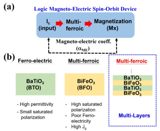
Figure 1.
(a) Multi-ferroic material is used largely for different kinds of applications including Logic Magneto-Electric Spin-Orbit (MESO) devices and (b) BaTiO3 (BTO) and BiFeO3 (BFO) are the well-known ferroelectric and multi-ferroic materials, respectively. In this work, we propose multi-layer BFO/BTO thin film structures with superior multi-ferroic properties.
Different sequence and thickness splits for BFO and BTO were composed for the study from ML-A to ML-C. The detailed final film scheme for ML-A, ML-B, and ML-C was BFO 100 nm/BTO 100 nm/BFO 100 nm/BTO 100 nm, BTO 100 nm/BFO 100 nm/BTO 100 nm/BFO 100 nm, and BFO 200 nm/BTO 200 nm, respectively. It should be noted that due to the limitation of the grain size to form the ferroelectric domain, the thickness of BFO and BTO film cannot be too thin (>100 nm). Upon the formation of ML BFO/BTO samples, part of the samples was put in an O2 atmosphere for Rapid Thermal Annealing (RTA) with an annealing temperature of 550 °C for 60 s.
For electrical measurements, square top electrodes of Pt (t = 50 nm) with an area of 1 mm2 were deposited on the ML BFO/BTO stack via DC sputtering with the shadow mask process. The phase structures and crystallographic orientation of the BFO film, BTO film, and ML BFO/BTO structures were characterized by X-ray Diffraction (XRD) and Raman spectroscopy. The small-angle X-ray scattering is a small-angle scattering technique by which nanoscale density differences in a sample can be quantified. The room temperature capacitance-voltage (C-V) and current-voltage (I-V) characteristics were measured by the semiconductor device electricity system (Agilent E4980A, Santa Clara, CA, USA). The P-E measurement and analysis were done with a ferroelectric and capacitor test station, provided by polyK Technologies, Philipsburg, PA, USA. The tested electric field range was from −1200 to 1200 kV/cm. The external magnetic field can be applied by the homemade system. We also note that all the electrical and magnetic analysis for the single layer BTO, single layer BFO, and ML BFO/BTO structures (ML-A to ML-C) with different thicknesses was normalized in this work in order to have a fair comparison.
3. Results and Discussion
Figure 2a shows the XRD patterns of the single BTO thin film with different annealing conditions from 600 to 800 °C. From the diffraction patterns, only weak peaks of (110) around 2θ = 32° and (200) around 2θ = 45° were observed. However, the growth of the (110) and (111) peaks and the splitting of the (200) peak indicated that the cubic-to-tetragonal phase transition of BTO occurred after the 60 s and 800 °C RTA process. On the other hand, Figure 2b shows the XRD patterns of the single BFO thin film with different annealing conditions from 550 to 650 °C. A better material quality of the BFO sample with post annealing at 550 °C with an O2 atmosphere was observed. In the BFO/BTO ML system, the complex BFO and BTO diffraction patterns in the split conditions from Condition A (ML-A) to Condition C (ML-C) are shown in Figure 2c. It can be observed that all prepared ML multi-ferroic BFO/BTO samples were polycrystalline in nature with a rhombohedral distortion for BFO and a tetragonal distortion for BTO [4], respectively.

Figure 2.
The X-ray Diffraction (XRD) patterns of the (a) single BaTiO3 (BTO) thin film, (b) single BiFeO3 (BFO) thin film with different post annealing conditions, and (c) multi-layer BFO/BTO structures from Condition A (ML-A) to Condition C (ML-C). RTA, Rapid Thermal Annealing.
Figure 3 shows the I-V curve for the samples of pure BTO thin film, pure BFO thin film, and ML BFO/BTO structures after 550 °C post annealing with an O2 atmosphere. The ferroelectric BTO films had a lower Jg, while the pure multi-ferroic BFO films had the largest one. With the optimization of ML BFO/BTO structures, we can find that the Jg of our split ML-A and ML-B can be close to that of the pure ferroelectric BTO sample, which had the lowest Jg level.
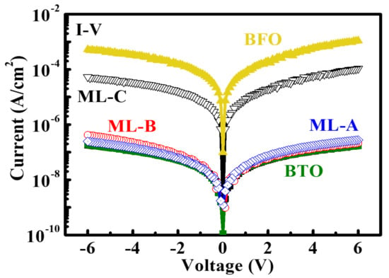
Figure 3.
The comparisons of the I-V curves on the pure 100 nm BaTiO3 (BTO) thin film and pure BiFeO3 (BFO) thin film with our designed multi-layer BaTiO3 (BTO)/BiFeO3 (BFO) structures from Condition A (ML-A) to Condition C (ML-C).
Besides the characteristics of the I-V measurements of these samples, the P-E curve was also measured and is shown in Figure 4. The multi-ferroic BFO thin film had the highest value of Ps (~75 µC/cm2), while the ferroelectric BTO thin film had a small value of ~15 µC/cm2. The Ec of both samples was close to 280 kV/cm. The enhanced polarization with the increase in the number of interfaces could be due to the presence of some interfacial polarization and trapped charges at the ML interfaces. Our developed ML BFO/BTO structure (ML-A) had values of Ps and Ec close to the pure multi-ferroic BFO thin film sample (Figure 4), and it also had the lowest Jg, the same as in the pure ferroelectric BTO sample (Figure 3). This indicates that the developed ML BFO/BTO structure (ML-A) can have the combined advantages of the pure BTO thin film (low Jg) and the pure BFO thin film (high Ps) at the same time.
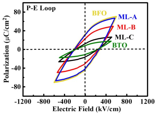
Figure 4.
The plots of the Polarization-Electric field (P-E) curves for the pure 100 nm BaTiO3 (BTO) thin film, the pure BiFeO3 (BFO) thin film, and our designed multi-layer (BaTiO3 (BTO)/BiFeO3 (BFO)) structures from Condition A (ML-A) to Condition C (ML-C).
In order to extract the value of αME to study the magneto-electric effect, the plot of the P-E curves for the pure 100 nm BFO thin film and our designed ML BFO/BTO structures for Condition A (ML-A) with different Mex. inputs (0, 600, 1200 Oe) was further measured and is shown in the Figure 5. The improvement in the magnetic property of ML-A could be due to the interfacial effects and the multi-ferroic coupling in the BFO/BTO multi-layered system.
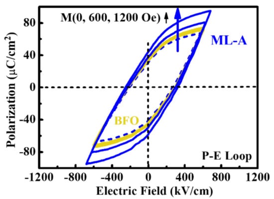
Figure 5.
The plot of P-E for the pure 100 nm BiFeO3 (BFO) and our designed multi-layer (BaTiO3 (BTO)/BiFeO3 (BFO)) structures for Condition A (ML-A) with different Magnetic (M) inputs.
Figure 6 shows the response and sensitivities of Ps with different Mex. inputs (0, 600, 1200 Oe) on both samples of the pure multi-ferroic BFO thin film and our proposed ML BFO/BTO structure (ML-A). The stronger magneto-electric effect (ΔPs/ΔMex. inputs) and a higher value of αME can be observed in our proposed ML BFO/BTO structure (ML-A) compared to those in the pure multi-ferroic BFO thin film sample.
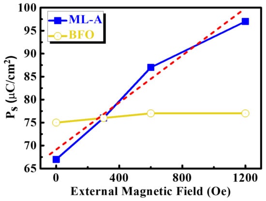
Figure 6.
The dependency of Ps with different external Magnetic (M) inputs on the pure 100 nm BiFeO3 (BFO) and our designed multi- layer (BaTiO3 (BTO)/BiFeO3 (BFO)) structures for Condition A (ML-A).
Figure 7 summarizes the key performance indices such as (a) Jg, (b) Ps, (c) Ec, and (d) ΔPs/ΔMex. inputs for the extraction of αME from the pure multi-ferroic BFO thin film and our developed ML BFO/BTO structures. Besides the similar values of Ps and Ec, our proposed ML BFO/BTO structure had a lower Jg (~5 × 10³ times) and a stronger magneto-electric effect (~25 times higher value upon the change of Ps with the Mex. inputs) than the pure multi-ferroic BFO thin film [7,8]. The superior material properties and the stronger magneto-electric effect of our proposed ML BFO/BTO structure (ML-A) provide for wider applications in industry, including magnetic sensors, logic spin electrics, and embedded magnetic memory.

Figure 7.
The comparisons of the (a) leakage current (Jg), (b) Ps, (c) Ec, and (d) ΔPs/ΔMex. for the pure 100 nm BiFeO3 (BFO) thin film and our designed multi-layer (ML) BaTiO3 (BTO)/BiFeO3 (BFO) structures for Condition A (ML-A) for the investigation of the magneto-electric effect. It shows that our proposed multi-layer BFO/BTO structures can have both a lower leakage current and a superior characteristics of ΔPs/ΔMex. at the same time.
4. Conclusions
The lower Jg and the higher response of Ps with different Mex. inputs and the value of αME were found in our proposed ML BFO/BTO structures compared to the pure multi-ferroic BFO thin-film sample. The ferro-electric BTO thin film had a higher ε and a smaller Ps, while the multi-ferroic BFO thin film had a higher Ps, poor ferroelectricity, and a higher Jg. The proposed ML BFO/BTO structures can combine the advantages of pure ferroelectric BTO and pure multi-ferroic BFO thin films. The superior material properties and the stronger magneto-electric effect in our proposed ML BFO/BTO structures provide for wider applications in industry, including magnetic sensors, logic spin electrics, and embedded magnetic memory.
Author Contributions
Conceptualization, M.-H.L. and S.-C.C.; Process, C.-W.H. and C.-M.Y.; methodology, Y.-C.F., L.-H.C., and B.-Z.L.; supervision, M.-H.L.; project administration, M.-H.L.; funding acquisition, S.-C.C. All authors have read and agreed to the published version of the manuscript.
Funding
This work is supported by the Ministry of Science and Technology (MOST), Taiwan, under Grants 109-2628-E-002-003-MY3 and 106-2221-E-002-199-MY3. The partial process support from Ray Lead Tech Co., Ltd., Taiwan, is also highly appreciated.
Informed Consent Statement
Not applicable.
Data Availability Statement
No new data were created or analyzed in this study. Data sharing is not applicable to this article.
Conflicts of Interest
No conflicts of Interest.
References
- Luong, V.S.; Su, Y.-H.; Lu, C.-C.; Jeng, J.-T.; Hsu, J.-H.; Liao, M.-H.; Wu, J.-C.; Lai, M.-H.; Chang, C.-R. Planarization, Fabrication and Characterization of Three-dimensional Magnetic Field Sensors. IEEE Trans. Nanotechnol. 2017, 17, 11–25. [Google Scholar] [CrossRef]
- Sharma, S.; Paliwal, A.; Tomar, M.; Gupta, V. Multiferroic BFO/BTO multilayer structures based magnetic field sensor. Phys. B Condens. Matter 2019, 571, 1–4. [Google Scholar] [CrossRef]
- Liao, M.-H.; Huang, S.-C. The demonstration of promising Ge n-type multi-gate-FETs with the magnetic FePt metal gate scheme. Appl. Phys. Lett. 2015, 107, 092103. [Google Scholar] [CrossRef]
- Liao, M.-H.; Huang, S.C.; Liu, C.Y.; Chen, P.G.; Kao, S.C.; Lien, C. The demonstration of colossal magneto-capacitance and “negative” capacitance effect with the promising characteristics of Jg-EOT and transistor’s performance on Ge (100) n-FETs by the novel magnetic gate stack scheme design. In Proceedings of the 2014 Symposium on VLSI Technology (VLSI-Technology): Digest of Technical Papers, Honolulu, HI, USA, 9 June 2014. [Google Scholar]
- Manipatruni, S.; Nikonov, D.E.; Young, I.A. Beyond CMOS computing with spin and polarization. Nat. Phys. 2018, 14, 338–343. [Google Scholar] [CrossRef]
- Manipatruni, S.; Nikonov, D.E.; Lin, C.-C.; Gosavi, T.A.; Liu, H.; Prasad, B.; Huang, Y.-L.; Bonturim, E.; Ramesh, R.; Young, I.A. Scalable energy-efficient magnetoelectric spin-orbit logic. Nature 2019, 565, 35–42. [Google Scholar] [CrossRef] [PubMed]
- Lien, C.; Hsieh, C.-F.; Wu, H.-S.; Wu, T.-C.; Wei, S.-J.; Chu, Y.-H.; Liao, M.-H.; Lee, M.H. The Demonstration of High-Performance Multilayer BaTiO3/BiFeO3 Stack MIM Capacitors. IEEE Trans. Electron Devices 2018, 65, 4834–4838. [Google Scholar] [CrossRef]
- Lien, C.; Hsieh, C.F.; Wu, T.C.; Yang, C.S.; Lee, M.H.; Xu, J.J.; Hu, C.W.; Huang, C.; Chang, S.Z.; Liao, M.H. The Investigation for Thickness-Dependent Electrical Performance on BaTiO3/BiFeO3 Bi-layer Ferro-magnetic Capacitors. IEEE Trans. Electron Devices 2020, 67, 3417–3423. [Google Scholar] [CrossRef]
- Sharma, S.; Tomar, M.; Kumar, A.; Puri, N.K.; Gupta, V. Stress induced enhanced polarization in multilayer BiFeO3/BaTiO3 structure with improved energy storage properties. AIP Adv. 2015, 5, 107216. [Google Scholar] [CrossRef]
- Yang, W.-S.; Sun, T.-H.; Chen, S.-C.; Jen, S.-U.; Guo, H.-J.; Liao, M.-H.; Chen, J.-R. Comparison of microstructure and magnetic properties in FePt alloy films deposited by direct current magnetron sputtering and high power impulse magnetron sputtering. J. Alloy. Compd. 2019, 803, 341–347. [Google Scholar] [CrossRef]
- Das, R.R.; Kim, D.M.; Baek, S.H.; Eom, C.-B.; Zavaliche, F.; Yang, S.Y.; Ramesh, R.; Chen, Y.B.; Pan, X.Q.; Ke, X.; et al. Synthesis and ferroelectric properties of epitaxial BiFeO3 thin films grown by sputtering. Appl. Phys. Lett. 2006, 88, 242904. [Google Scholar] [CrossRef]
- Chang, H.W.; Yuan, F.T.; Shih, C.W.; Wang, C.R.; Chang, W.C.; Jen, S.U. Sputter-prepared BiFeO3 (001) films on L10 FePt (001)/glass substrates. J. Appl. Phys. 2012, 111, 07D918. [Google Scholar] [CrossRef]
- Ihlefeld, J.F.; Podraza, N.J.; Liu, Z.K.; Rai, R.C.; Xu, X.; Heeg, T.; Chen, Y.B.; Li, J.; Collins, R.W.; Musfeldt, J.L.; et al. Optical bandgap of BiFeO3 grown by molecular-beam epitaxy. Appl. Phys. Lett. 2008, 92, 142908. [Google Scholar] [CrossRef]
Publisher’s Note: MDPI stays neutral with regard to jurisdictional claims in published maps and institutional affiliations. |
© 2021 by the authors. Licensee MDPI, Basel, Switzerland. This article is an open access article distributed under the terms and conditions of the Creative Commons Attribution (CC BY) license (http://creativecommons.org/licenses/by/4.0/).