
Exciton Up-Conversion by Well-Distributed Carbon Quantum Dots in Luminescent Materials for an Efficient Organic Light-Emitting Diode


Abstract
:1. Introduction
2. Materials and Methods
3. Results
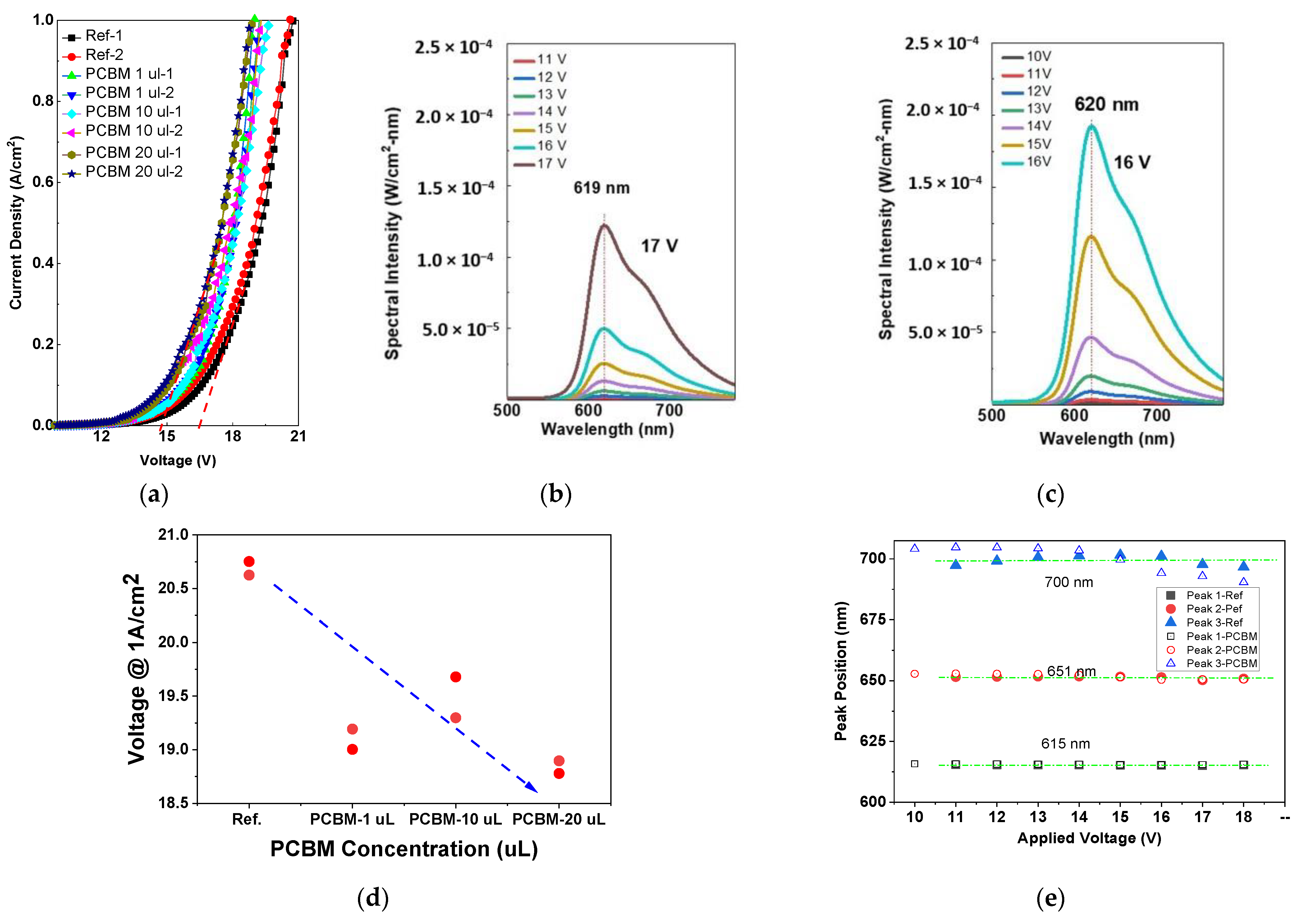
3.1. Current–Voltage–Luminance Characteristics
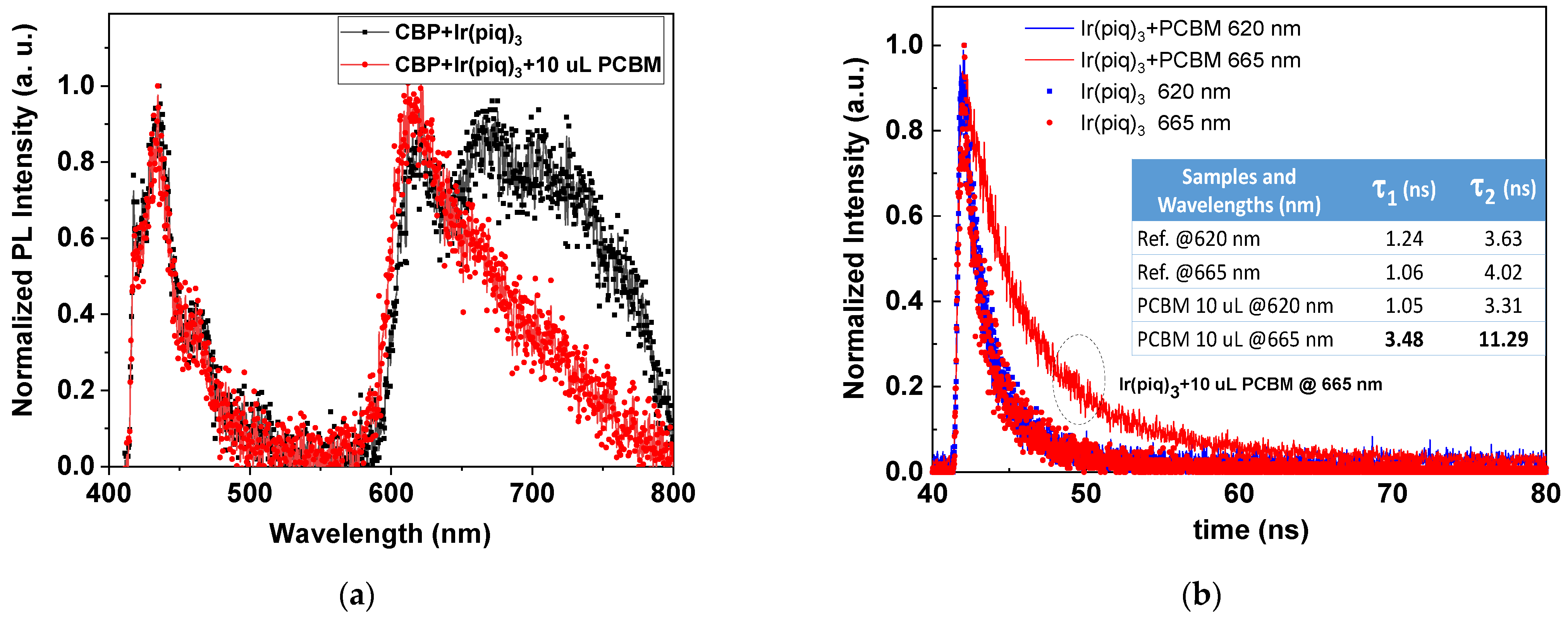
3.2. Time-Resolved Photoluminescence
4. Discussion
5. Conclusions
Author Contributions
Funding
Institutional Review Board Statement
Informed Consent Statement
Data Availability Statement
Conflicts of Interest
References
- Jou, J.-H.; Kumar, S.; Agrawal, A.; Li, T.-H.; Sahoo, S. Approaches for fabricating high efficiency organic light emitting diodes. J. Mater. Chem. C 2015, 3, 2974–3002. [Google Scholar] [CrossRef]
- Lee, J.-H.; Chen, C.-H.; Lee, P.-H.; Lin, H.-Y.; Leung, M.-K.; Chiu, T.-L.; Lin, C.-F. Blue organic light-emitting diodes: Current status, challenges, and future outlook. J. Mater. Chem. C 2019, 7, 5874–5888. [Google Scholar] [CrossRef]
- Liu, Z.; Helander, M.G.; Wang, Z.; Lu, Z. Band Alignment at Anode/Organic Interfaces for Highly Efficient Simplified Blue-Emitting Organic Light-Emitting Diodes. J. Phys. Chem. C 2010, 114, 16746–16749. [Google Scholar] [CrossRef]
- Xiao, H.; Zhang, X.; Wang, J.-Y.; Zhang, L.-Y.; Zhang, Q.-C.; Chen, Z.-N. Enhancing Phosphorescence through Rigidifying the Conformation to Achieve High-Efficiency OLEDs by Modified PEDOT. ACS Appl. Mater. Interfaces 2019, 11, 45853–45861. [Google Scholar] [CrossRef] [PubMed]
- Cebrián, C.; Mauro, M. Recent advances in phosphorescent platinum complexes for organic light-emitting diodes. Beilstein J. Org. Chem. 2018, 14, 1459–1481. [Google Scholar] [CrossRef] [PubMed]
- Guo, R.; Zhang, W.; Zhang, Q.; Lv, X.; Wang, L. Efficient deep red phosphorescent OLEDs using 1,2,4-thiadiazole core-based novel bipolar host with low efficiency roll-off. Front. Optoelectron. 2018, 11, 375–384. [Google Scholar] [CrossRef]
- Choy, W.C.H.; Chan, W.K.; Yuan, Y. Recent Advances in Transition Metal Complexes and Light-Management Engineering in Organic Optoelectronic Devices. Adv. Mater. 2014, 26, 5368–5399. [Google Scholar] [CrossRef]
- Fan, C.; Yang, C. Yellow/orange emissive heavy-metal complexes as phosphors in monochromatic and white organic light-emitting devices. Chem. Soc. Rev. 2014, 43, 6439–6469. [Google Scholar] [CrossRef]
- Minaev, B.; Baryshnikov, G.; Agren, H. Principles of phosphorescent organic light emitting devices. Phys. Chem. Chem. Phys. 2014, 16, 1719–1758. [Google Scholar] [CrossRef]
- Sree, V.G.; Maheshwaran, A.; Kim, H.; Park, H.-Y.; Kim, Y.; Lee, J.C.; Song, M.; Jin, S.-H. Synthesis and Characterization of Highly Efficient Solution-Processable Green Ir(III) Complexes with High Current Efficiency and Very Low Efficiency Roll-Off. Adv. Funct. Mater. 2018, 28, 1804714. [Google Scholar] [CrossRef]
- Igawa, S.; Hashimoto, M.; Kawata, I.; Yashima, M.; Hoshino, M.; Osawa, M. Highly efficient green organic light-emitting diodes containing luminescent tetrahedral copper(i) complexes. J. Mater. Chem. C 2013, 1, 542–551. [Google Scholar] [CrossRef]
- Li, L.-K.; Tang, M.-C.; Lai, S.-L.; Ng, M.; Kwok, W.-K.; Chan, M.-Y.; Yam, V.W.-W. Strategies towards rational design of gold(iii) complexes for high-performance organic light-emitting devices. Nat. Photonics 2019, 13, 185–191. [Google Scholar] [CrossRef]
- Kawamura, Y.; Goushi, K.; Brooks, J.; Brown, J.J.; Sasabe, H.; Adachi, C. 100% phosphorescence quantum efficiency of Ir(III) complexes in organic semiconductor films. Appl. Phys. Lett. 2005, 86, 071104. [Google Scholar] [CrossRef]
- Baldo, M.A.; O'Brien, D.F.; You, Y.; Shoustikov, A.; Sibley, S.; Thompson, M.E.; Forrest, S.R. Highly efficient phosphorescent emission from organic electroluminescent devices. Nature 1998, 395, 151–154. [Google Scholar] [CrossRef]
- Chung-Chih, W.; Sturm, J.C.; Register, R.A.; Jing, T.; Dana, E.P.; Tnompson, M.E. Efficient organic electroluminescent devices using single-layer doped polymer thin films with bipolar carrier transport abilities. IEEE Trans. Electron. Devices 1997, 44, 1269–1281. [Google Scholar] [CrossRef]
- Kim, H.S.; Park, S.-R.; Suh, M.C. Concentration Quenching Behavior of Thermally Activated Delayed Fluorescence in a Solid Film. J. Phys. Chem. C 2017, 121, 13986–13997. [Google Scholar] [CrossRef]
- Pıravadılı Mucur, S.; Tekin, E.; San, S.E.; Duygulu, Ö.; Öztürk, H.Ü.; Utkan, G.; Denizci, A.A. A novel PLED architecture containing biologically synthesized gold nanoparticles and ultra thin silver layer. Opt. Mater. 2015, 47, 297–303. [Google Scholar] [CrossRef]
- Kim, D.H.; Kim, T.W. Efficiency enhancement of organic light-emitting devices due to a localized surface plasmonic resonance effect of poly(4-butylphenyl-diphenyl-amine):dodecanethiol functionalized Au nanocomposites. Opt. Express 2015, 23, 11211–11220. [Google Scholar] [CrossRef] [PubMed]
- Xiao, Y.; Yang, J.P.; Cheng, P.P.; Zhu, J.J.; Xu, Z.Q.; Deng, Y.H.; Lee, S.T.; Li, Y.Q.; Tang, J.X. Surface plasmon-enhanced electroluminescence in organic light-emitting diodes incorporating Au nanoparticles. Appl. Phys. Lett. 2012, 100, 013308. [Google Scholar] [CrossRef] [Green Version]
- Williams, C.D.; Robles, R.O.; Zhang, M.; Li, S.; Baughman, R.H.; Zakhidov, A.A. Multiwalled carbon nanotube sheets as transparent electrodes in high brightness organic light-emitting diodes. Appl. Phys. Lett. 2008, 93, 183506. [Google Scholar] [CrossRef]
- Shi, S.; Silva, S.R.P. High luminance organic light-emitting diodes with efficient multi-walled carbon nanotube hole injectors. Carbon 2012, 50, 4163–4170. [Google Scholar] [CrossRef] [Green Version]
- Pei, Z.; Chiang, W.; Shih, H.; Chang, H.; Yang, J. Using Distributed Energy States of Graphene Quantum Dots for an Efficient Hole-Injection Media in an Organic Electroluminescent Device. IEEE Electron. Device Lett. 2018, 39, 1912–1915. [Google Scholar] [CrossRef]
- Zhang, Q.; Li, B.; Huang, S.; Nomura, H.; Tanaka, H.; Adachi, C. Efficient blue organic light-emitting diodes employing thermally activated delayed fluorescence. Nat. Photonics 2014, 8, 326–332. [Google Scholar] [CrossRef]
- Yu, Y.-J.; Wang, X.-Q.; Liu, J.-F.; Jiang, Z.-Q.; Liao, L.-S. Harvesting triplet excitons for near-infrared electroluminescence via thermally activated delayed fluorescence channel. iScience 2021, 24, 102123. [Google Scholar] [CrossRef] [PubMed]
- Endo, A.; Ogasawara, M.; Takahashi, A.; Yokoyama, D.; Kato, Y.; Adachi, C. Thermally Activated Delayed Fluorescence from Sn4+–Porphyrin Complexes and Their Application to Organic Light Emitting Diodes—A Novel Mechanism for Electroluminescence. Adv. Mater. 2009, 21, 4802–4806. [Google Scholar] [CrossRef]
- Endo, A.; Sato, K.; Yoshimura, K.; Kai, T.; Kawada, A.; Miyazaki, H.; Adachi, C. Efficient up-conversion of triplet excitons into a singlet state and its application for organic light emitting diodes. Appl. Phys. Lett. 2011, 98, 083302. [Google Scholar] [CrossRef]
- Uoyama, H.; Goushi, K.; Shizu, K.; Nomura, H.; Adachi, C. Highly efficient organic light-emitting diodes from delayed fluorescence. Nature 2012, 492, 234–238. [Google Scholar] [CrossRef]
- Yin, X.; He, Y.; Wang, X.; Wu, Z.; Pang, E.; Xu, J.; Wang, J.-A. Recent Advances in Thermally Activated Delayed Fluorescent Polymer—Molecular Designing Strategies. Front. Chem. 2020, 8, 725. [Google Scholar] [CrossRef] [PubMed]
- Kim, J.H.; Lee, D.R.; Han, S.H.; Lee, J.Y. Over 20% external quantum efficiency in red thermally activated delayed fluorescence organic light-emitting diodes using a reverse intersystem crossing activating host. J. Mater. Chem. C 2018, 6, 5363–5368. [Google Scholar] [CrossRef]
- Drummy, L.F.; Davis, R.J.; Moore, D.L.; Durstock, M.; Vaia, R.A.; Hsu, J.W.P. Molecular-Scale and Nanoscale Morphology of P3HT:PCBM Bulk Heterojunctions: Energy-Filtered TEM and Low-Dose HREM. Chem. Mater. 2011, 23, 907–912. [Google Scholar] [CrossRef]
- Sun, Y.; Han, Y.; Liu, J. Controlling PCBM aggregation in P3HT/PCBM film by a selective solvent vapor annealing. Chin. Sci. Bull. 2013, 58, 2767–2774. [Google Scholar] [CrossRef] [Green Version]
- Paternò, G.; Warren, A.J.; Spencer, J.; Evans, G.; Sakai, V.G.; Blumberger, J.; Cacialli, F. Micro-focused X-ray diffraction characterization of high-quality (6,6)-phenyl-C61-butyric acid methyl ester single crystals without solvent impurities. J. Mater. Chem. C 2013, 1, 5619–5623. [Google Scholar] [CrossRef] [Green Version]
- Dutta, M.; Thirugnanam, L.; Trinh, P.V.; Fukata, N. High Efficiency Hybrid Solar Cells Using Nanocrystalline Si Quantum Dots and Si Nanowires. ACS Nano 2015, 9, 6891–6899. [Google Scholar] [CrossRef] [PubMed]
- Chanyawadee, S.; Lagoudakis, P.G.; Harley, R.T.; Lidzey, D.G.; Henini, M. Nonradiative exciton energy transfer in hybrid organic-inorganic heterostructures. Phys. Rev. B 2008, 77, 193402. [Google Scholar] [CrossRef] [Green Version]
- van de Haar, M.A.; Berends, A.C.; Krames, M.R.; Chepyga, L.; Rabouw, F.T.; Meijerink, A. Eu3+ Sensitization via Nonradiative Interparticle Energy Transfer Using Inorganic Nanoparticles. J. Phys. Chem. Lett. 2020, 11, 689–695. [Google Scholar] [CrossRef] [PubMed]
- de Vries, X.; Friederich, P.; Wenzel, W.; Coehoorn, R.; Bobbert, P.A. Triplet exciton diffusion in metalorganic phosphorescent host-guest systems from first principles. Phys. Rev. B 2019, 99, 205201. [Google Scholar] [CrossRef] [Green Version]
- Tregnago, G.; Wykes, M.; Paternò, G.M.; Beljonne, D.; Cacialli, F. Low-Temperature Photoluminescence Spectroscopy of Solvent-Free PCBM Single-Crystals. J. Phys. Chem. C 2015, 119, 11846–11851. [Google Scholar] [CrossRef]
- Reineke, S.; Walzer, K.; Leo, K. Triplet-exciton quenching in organic phosphorescent light-emitting diodes with Ir-based emitters. Phys. Rev. B 2007, 75, 125328. [Google Scholar] [CrossRef]
- Litvin, A.P.; Parfenov, P.S.; Ushakova, E.V.; Vorsina, T.A.; Simões Gamboa, A.L.; Fedorov, A.V.; Baranov, A.V. FRET-Activated Delayed Fluorescence in Densely Packed PbS Quantum-Dot Ensembles. J. Phys. Chem. C 2015, 119, 17016–17022. [Google Scholar] [CrossRef]
- de Vries, X.; Coehoorn, R.; Bobbert, P.A. High energy acceptor states strongly enhance exciton transfer between metal organic phosphorescent dyes. Nat. Commun. 2020, 11, 1292. [Google Scholar] [CrossRef] [Green Version]
- Tao, Y.; Yuan, K.; Chen, T.; Xu, P.; Li, H.; Chen, R.; Zheng, C.; Zhang, L.; Huang, W. Thermally Activated Delayed Fluorescence Materials towards the Breakthrough of Organoelectronics. Adv. Mater. 2014, 26, 7931–7958. [Google Scholar] [CrossRef] [PubMed]
- Efros, A.L.; Nesbitt, D.J. Origin and control of blinking in quantum dots. Nat. Nanotechnol. 2016, 11, 661–671. [Google Scholar] [CrossRef] [PubMed]
- Galland, C.; Ghosh, Y.; Steinbrück, A.; Sykora, M.; Hollingsworth, J.A.; Klimov, V.I.; Htoon, H. Two types of luminescence blinking revealed by spectroelectrochemistry of single quantum dots. Nature 2011, 479, 203–207. [Google Scholar] [CrossRef] [PubMed]
- Foxman, E.B.; McEuen, P.L.; Meirav, U.; Wingreen, N.S.; Meir, Y.; Belk, P.A.; Belk, N.R.; Kastner, M.A.; Wind, S.J. Effects of quantum levels on transport through a Coulomb island. Phys. Rev. B 1993, 47, 10020–10023. [Google Scholar] [CrossRef] [PubMed]
- Baldo, M.A.; Forrest, S.R. Transient analysis of organic electrophosphorescence: I. Transient analysis of triplet energy transfer. Phys. Rev. B 2000, 62, 10958–10966. [Google Scholar] [CrossRef]
- Zhao, D.; Liu, H.; Miao, Y.; Wang, H.; Zhao, B.; Hao, Y.; Zhu, F.; Xu, B. A red tandem organic light-emitting diode based on organic photovoltaic-type charge generation layer. Org. Electron. 2016, 32, 1–6. [Google Scholar] [CrossRef]


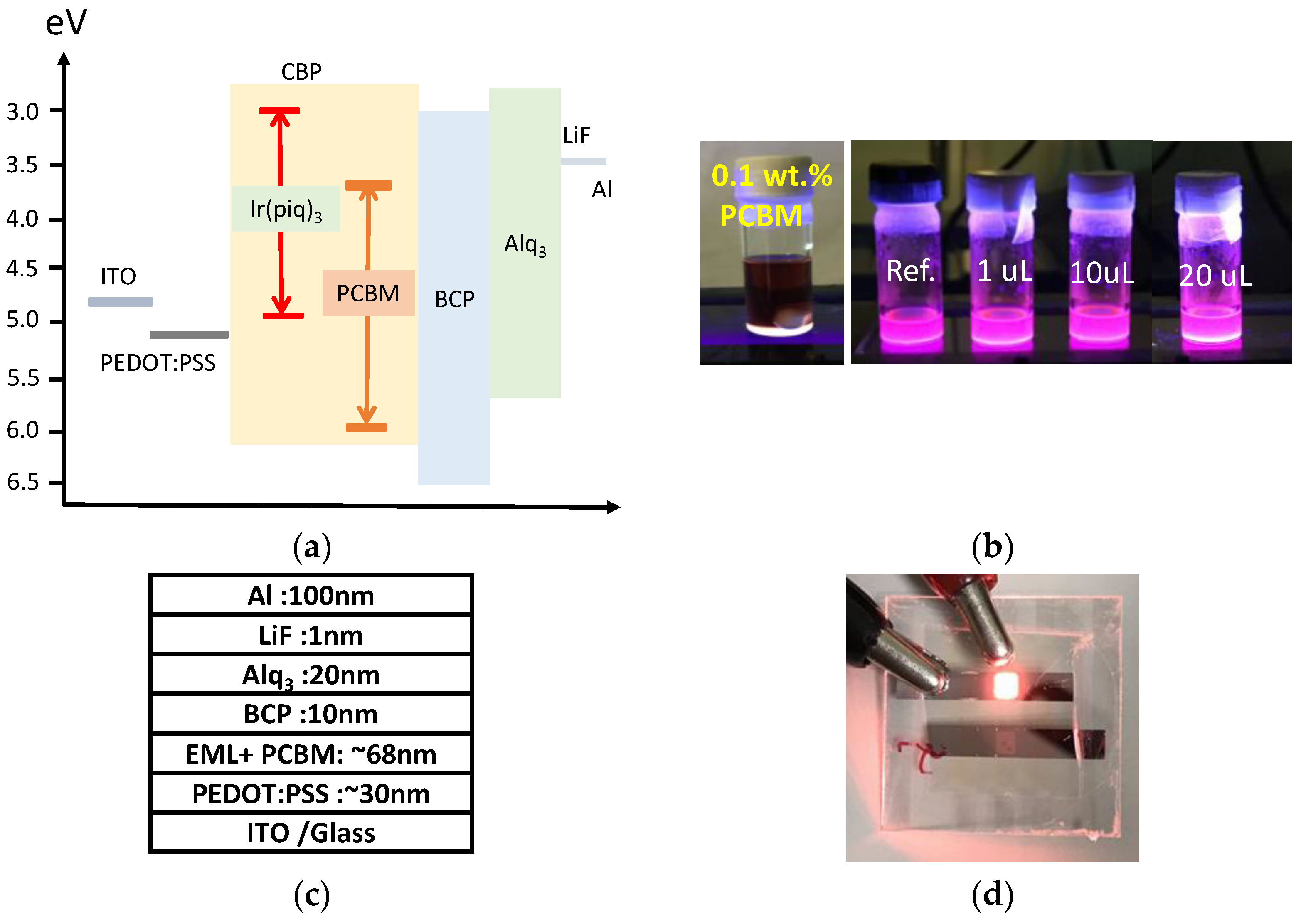
| Sample # | PCBM a Solution (µL) | The Concentration of PCBM in Luminescent Solution (wt. %) | Concentration of Ir(piq)3 in Luminescent Solution (wt. %) |
|---|---|---|---|
| Ref. | -- | -- | 0.144 |
| 1 | 1 | 0.0001 | 0.144 |
| 2 | 10 | 0.001 | 0.144 |
| 3 | 20 | 0.002 | 0.144 |
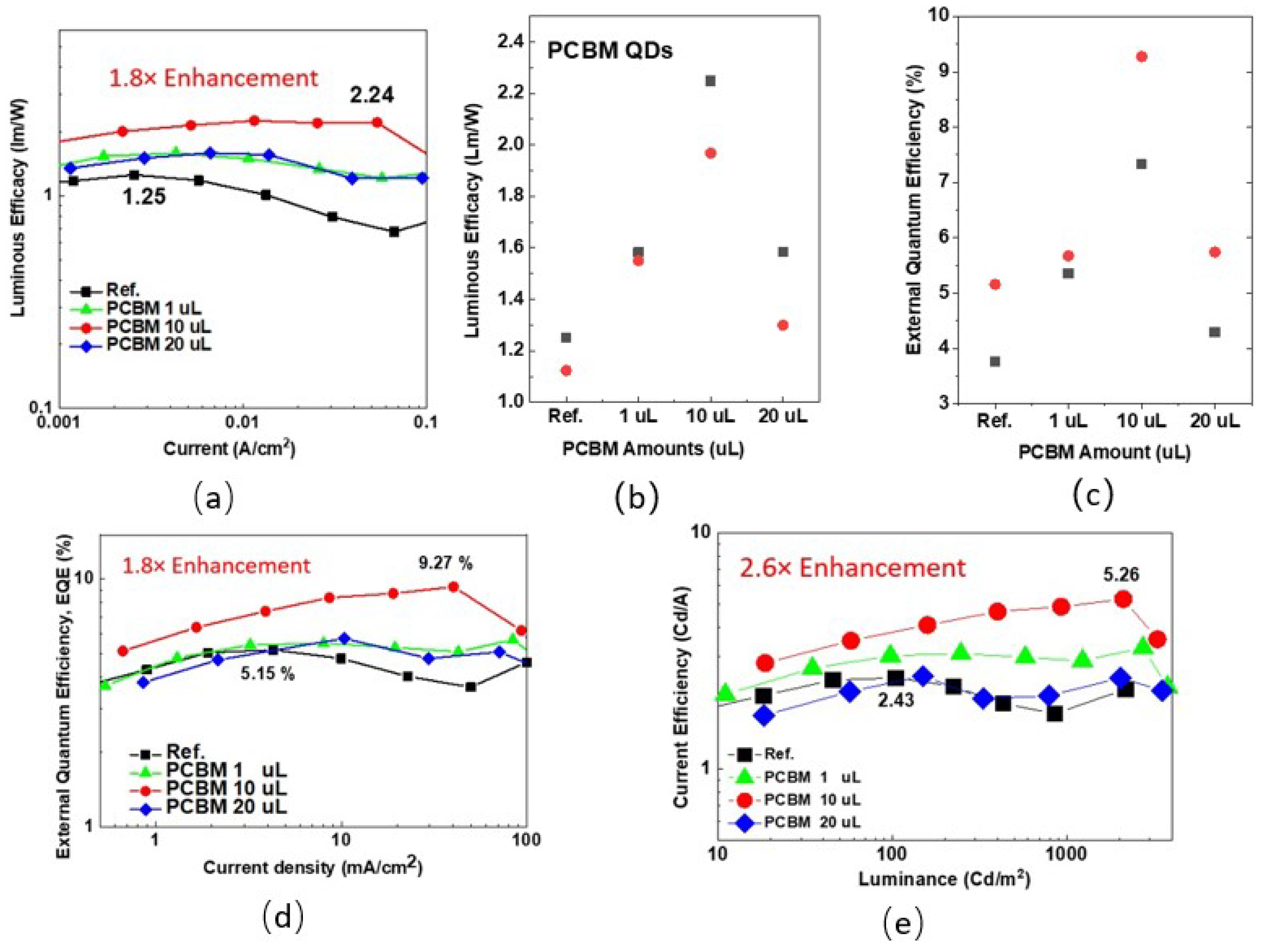
| Sample # | PCBM Concentration, wt % | External Quantum Efficiency (%) (ηmax/ηavg.) | Current Efficiency (Cd/A) (max./avg.) | Luminous Efficacy (lm/W) (max./avg.) a |
|---|---|---|---|---|
| Ref. | -- | 5.15/4.45 | 2.43/2.09 | 1.25/1.19 |
| 1 | 10−4 | 5.67/5.51 | 3.26/3.17 | 1.58/1.57 |
| 2 | 10−3 | 9.27/8.30 | 5.25/4.35 | 2.25/2.11 |
| 3 | 2 × 10⁻³ | 5.74/5.01 | 3.21/2.85 | 1.58/1.44 |
| Method | Materials | Wavelength (nm) | EQE (%) | Enhancement (%) | Ref. |
|---|---|---|---|---|---|
| New materials + Anode Engineering | Pt2Au | 503 | 18.3 | 93 | [10] |
| New host materials | Ir(piq)3 | 620 | 16.2 | N/A | [12] |
| Gold NPs in HTL | MEH-PPV | 596 | 1.09 | 113 | [17] |
| CNT in HTL | Alq3 | 520 | 2.34 | 49 | [21] |
| New Host and TADF | HAP-3TPA | 577 | 24.3 | 30 | [29] |
| PCBM Doping | Ir(piq)3 | 620 | 9.27 | 80 | This work |
Publisher’s Note: MDPI stays neutral with regard to jurisdictional claims in published maps and institutional affiliations. |
© 2022 by the authors. Licensee MDPI, Basel, Switzerland. This article is an open access article distributed under the terms and conditions of the Creative Commons Attribution (CC BY) license (https://creativecommons.org/licenses/by/4.0/).
Share and Cite
Pei, Z.; Wei, H.-Y.; Liu, Y.-C. Exciton Up-Conversion by Well-Distributed Carbon Quantum Dots in Luminescent Materials for an Efficient Organic Light-Emitting Diode. Nanomaterials 2022, 12, 1174. https://doi.org/10.3390/nano12071174
Pei Z, Wei H-Y, Liu Y-C. Exciton Up-Conversion by Well-Distributed Carbon Quantum Dots in Luminescent Materials for an Efficient Organic Light-Emitting Diode. Nanomaterials. 2022; 12(7):1174. https://doi.org/10.3390/nano12071174
Chicago/Turabian StylePei, Zingway, Han-Yun Wei, and Yi-Chun Liu. 2022. "Exciton Up-Conversion by Well-Distributed Carbon Quantum Dots in Luminescent Materials for an Efficient Organic Light-Emitting Diode" Nanomaterials 12, no. 7: 1174. https://doi.org/10.3390/nano12071174
APA StylePei, Z., Wei, H.-Y., & Liu, Y.-C. (2022). Exciton Up-Conversion by Well-Distributed Carbon Quantum Dots in Luminescent Materials for an Efficient Organic Light-Emitting Diode. Nanomaterials, 12(7), 1174. https://doi.org/10.3390/nano12071174