Abstract
This paper presents a composite disturbance-tolerant control framework for quadrotor unmanned aerial vehicles (UAVs). By constructing an enhanced dynamic model that incorporates parameter uncertainties, external disturbances, and actuator faults and considering the inherent underactuated and highly coupled characteristics of the UAV, a novel robust adaptive sliding mode controller (RASMC) is designed. The controller adopts a hierarchical adaptive mechanism and utilizes a dual-loop composite adaptive law to achieve the online estimation of system parameters and fault information. Using the Lyapunov method, the asymptotic stability of the closed-loop system is rigorously proven. Simulation results demonstrate that, under the combined effects of external disturbances and actuator faults, the RASMC effectively suppresses position errors (<0.05 m) and attitude errors (<0.02 radians), significantly outperforming traditional ADRC and LQR control methods. Further analysis shows that the proposed adaptive law enables the precise online estimation of aerodynamic coefficients and disturbance boundaries during actual flights, with estimation errors controlled within ±10%. Moreover, compared to ADRC and LQR, RASMC reduces the settling time by more than 50% and the tracking overshoot by over 70% while using the () approximation to eliminate chattering. Prototype experiments validate the fact that the method achieves centimeter-level trajectory tracking under real uncertainties, demonstrating the superior performance and robustness of the control framework in complex flight missions.
1. Introduction
Quadrotor unmanned aerial vehicles (UAVs) have been widely employed in aerial photography, search and rescue, mapping, and reconnaissance due to their vertical takeoff and landing capabilities, high maneuverability, and cost-effectiveness [1]. Their ability to hover and operate in confined spaces provides a distinct advantage over fixed-wing UAVs, which require dedicated takeoff and landing sites. However, as UAV applications continue to expand, dynamic disturbances such as gusts and sudden payload variations, along with internal uncertainties—including nonlinear dynamics and actuator faults—pose significant challenges to the robustness of control systems [2]. To enhance disturbance rejection and mission adaptability, prior research has explored finite-time observers and super-twisting controllers [2], intelligent path-planning algorithms [3], and lightweight visual positioning techniques [4]. Nevertheless, conventional control strategies struggle to maintain both precise trajectory tracking and system fault tolerance in the presence of internal disturbances such as actuator failures [5]. In particular, partial actuator faults exacerbate the system’s inherent under-actuation [6] and strong dynamic coupling [7], leading to increased control errors and a heightened risk of mission failure.
In the domain of parameter uncertainty compensation for quadrotor UAVs, significant progress has been achieved in recent years; however, critical challenges remain. Ben Abdi et al. and Ben Niu et al. enhanced trajectory tracking stability by optimizing the ant colony optimization (ACO) algorithm. However, their approach is constrained by an offline parameter tuning mechanism, limiting their adaptability to dynamic environments [8,9]. Nguyen et al. integrated Recursive Minimum Error Entropy (RMEE) filtering with adaptive sliding mode control to improve robustness against non-Gaussian noise [10]. Nevertheless, this method compromises real-time performance and hardware deployment feasibility. Similarly, Zhang et al. and Kaba et al. significantly improved UAV state estimation accuracy in noisy and disturbed environments through particle filtering. However, residual attitude estimation errors persist under extreme environmental conditions [11,12]. The linear control strategies proposed by Zou et al. and Vaca offer theoretical advantages in addressing the complex dynamics and parameter uncertainties of UAVs, yet their robustness against strong perturbations remains inadequate [13,14]. Despite these advancements, fundamental bottlenecks in parameter uncertainty compensation still need to be overcome. Traditional architectures based on fixed-gain controllers or offline optimization strategies fail to achieve the online dynamic identification of flight parameters, leading to cumulative control input errors. Moreover, existing uncertainty compensation strategies struggle to balance computational complexity with the system’s real-time requirements, thereby constraining control performance in complex operational scenarios. Addressing these challenges is essential to advancing robust and adaptive control frameworks for quadrotor UAVs. Likewise, within microgrid control, streamlining the implementation of complex strategies (e.g., Model Predictive Control—MPC) and mitigating computational burdens to enhance scalability and robustness remains a critical research focus [15].
In addressing the trajectory tracking control problem of quadrotor UAVs under external disturbances, current research has explored diverse, innovative approaches. Mofid et al. and Singh et al. have designed robust controllers to enhance UAV control performance in disturbed environments; however, their adaptability to time-varying disturbances remains a challenge [16,17]. Dou et al. and Yang et al. have integrated adaptive dynamic programming (ADP) with disturbance observers to compensate for external disturbances, yet their methods lack generalization capabilities when faced with sudden parameter variations [18,19]. Finite-time disturbance observers proposed by Wang et al. and Huang et al. optimize transient performance but struggle to balance observation accuracy and computational complexity [20,21]. Despite significant advancements in this field, critical challenges persist. The robustness of existing control strategies in suppressing high-frequency dynamic disturbances remains inadequate, and disturbance estimators commonly face a trade-off between convergence speed and accuracy. Furthermore, current controller design methodologies rely heavily on precise model parameters and exhibit poor adaptability when encountering unmodeled dynamics. Overcoming these limitations is essential to developing more resilient and adaptive UAV control systems.
In the coupled control of dynamic disturbances and parameter uncertainties, recent research has made significant breakthroughs. Zhang et al. and Yang et al. employed adaptive dynamic programming (ADP) to achieve the synergistic optimization of disturbance suppression and control costs; however, their approaches rely on additional compensation techniques [19,22]. Mehmood et al. and Bao et al. integrated sliding-mode control with adaptive control, leveraging the robustness of the sliding mode to address nonlinearities while using adaptive laws to compensate for parameter uncertainties and external disturbances. Nevertheless, achieving real-time accurate compensation in dynamic environments remains a challenge [23,24]. The fault-tolerant control framework proposed by Imran et al. significantly enhances fault-disturbance coupling suppression. However, its adaptive law design is constrained by the requirement for exact model linearization and prior knowledge of the upper bound of disturbances [25]. Labbadi et al. and Hou et al. combined multiple control methods to improve overall performance, yet they faced limitations regarding robustness due to sliding mode chattering, and the compound effects of multi-source disturbance coupling remain insufficiently explored [26,27]. Lei et al. utilized geometric control based on an extended Kalman filter (EKF) to enable the real-time estimation of inertial parameters, but sensor noise can induce estimation bias. Despite these advancements, critical challenges remain [28]. The trade-off between response lag and compensation accuracy in high-frequency dynamic disturbance suppression persists, and existing strategies lack a rigorous stability guarantee for actuator fault disturbance coupled with suppression. Additionally, the strong dependence of current control architectures on precise model parameters limits their adaptability to complex and uncertain environments. Addressing these issues is crucial for developing more robust and adaptive UAV control frameworks.
Significant research has been conducted on the reliable flight control of quadrotor UAVs in complex environments, particularly in addressing actuator faults and enhancing fault tolerance. Lee et al. designed a multimodal neural adaptive observer (MNAO) to improve fault identification, significantly reducing false alarm rates and enhancing diagnostic speed. However, its performance heavily depends on prior knowledge of fault modes [29]. Zhong et al. and Okada et al. employed Kalman filters to enhance robustness by reducing the reliance on precise dynamic models for fault and disturbance estimation. Nonetheless, their methods are limited by their insufficient capacity for handling concurrent multi-fault scenarios [30,31]. Liu et al. proposed a robust composite sliding mode controller (RCSMC) with an adaptive finite-time epochal state observer (AFTESO) to improve resilience against parameter uncertainties and actuator faults. However, its effectiveness in complex environments remains unverified, and its simplified fault diagnosis module may affect long-term reliability [32]. Sanjeev Ranjan et al. introduced a fusion fixed-time state observer (FTSO) with adaptive neural fault-tolerant control (RANFTC), which mitigates gain overestimation and chattering issues in sliding-mode control while improving steady-state accuracy and robustness [33]. However, their approach does not explicitly consider scenarios where multiple types of faults occur simultaneously. To address these limitations, Qilong Wu et al. proposed a fixed-time extended state observer (FXTESO)-based fault-tolerant control strategy, modeling actuator faults, external disturbances, and model coupling as “total perturbations” [34]. Their approach effectively enhanced multi-disturbance compensation and dynamic performance optimization. Table 1 summarizes the state-of-the-art research on robust trajectory tracking and fault-tolerant control for quadrotor UAVs.

Table 1.
An overview of the current state of the art of research on robust trajectory tracking fault-tolerant control for quadrotor UAVs.
However, its robustness under simultaneous multiple fault conditions has not been thoroughly analyzed. Despite the substantial progress in improving system reliability, challenges remain in actuator fault tolerance mechanisms, particularly in handling hardware failures under complex operational conditions. When multiple influencing factors act concurrently, system robustness remains inadequate, highlighting the need for further advancements in resilient fault-tolerant control strategies for UAVs.
In this study, a robust adaptive sliding mode controller with rigorous theoretical guarantees is proposed to address the control challenges of quadrotor UAVs operating in complex flight environments. While extensive research has been conducted on control schemes under parameter uncertainties, external disturbances, and actuator failures, a general robust control framework capable of simultaneously handling multiple uncertainties has yet to be fully established.
To bridge this gap, this study introduces the following key innovations: (1) To address parameter uncertainties during UAV flights, an adaptive law is designed to effectively estimate unknown system parameters. The estimated values are then incorporated into the rotor control input equations, replacing the actual but unknown parameters. This approach ensures the accuracy of control inputs, thereby improving UAV path-following performance. (2) The proposed control law is rigorously proven to guarantee the asymptotic stability of the UAV under completely unknown external disturbances and actuator failures. (3) The superior trajectory tracking accuracy and strong disturbance rejection capability of the proposed control strategy are validated through simulation experiments and comparative analyses with the linear quadratic regulator (LQR) and active disturbance rejection control (ADRC). These contributions collectively advance the development of a more resilient and adaptive UAV control framework, enhancing flight stability and robustness in uncertain environments.
The remainder of this paper is organized as follows: Section 2 introduces the mathematical model of the quadrotor UAV and formulates the problem statement. Section 3 details the proposed control strategy and provides a rigorous stability analysis. Section 4 presents the simulation results to validate the effectiveness of the proposed approach. Finally, Section 5 summarizes the key findings and discusses potential directions for future research.
2. Materials and Methods
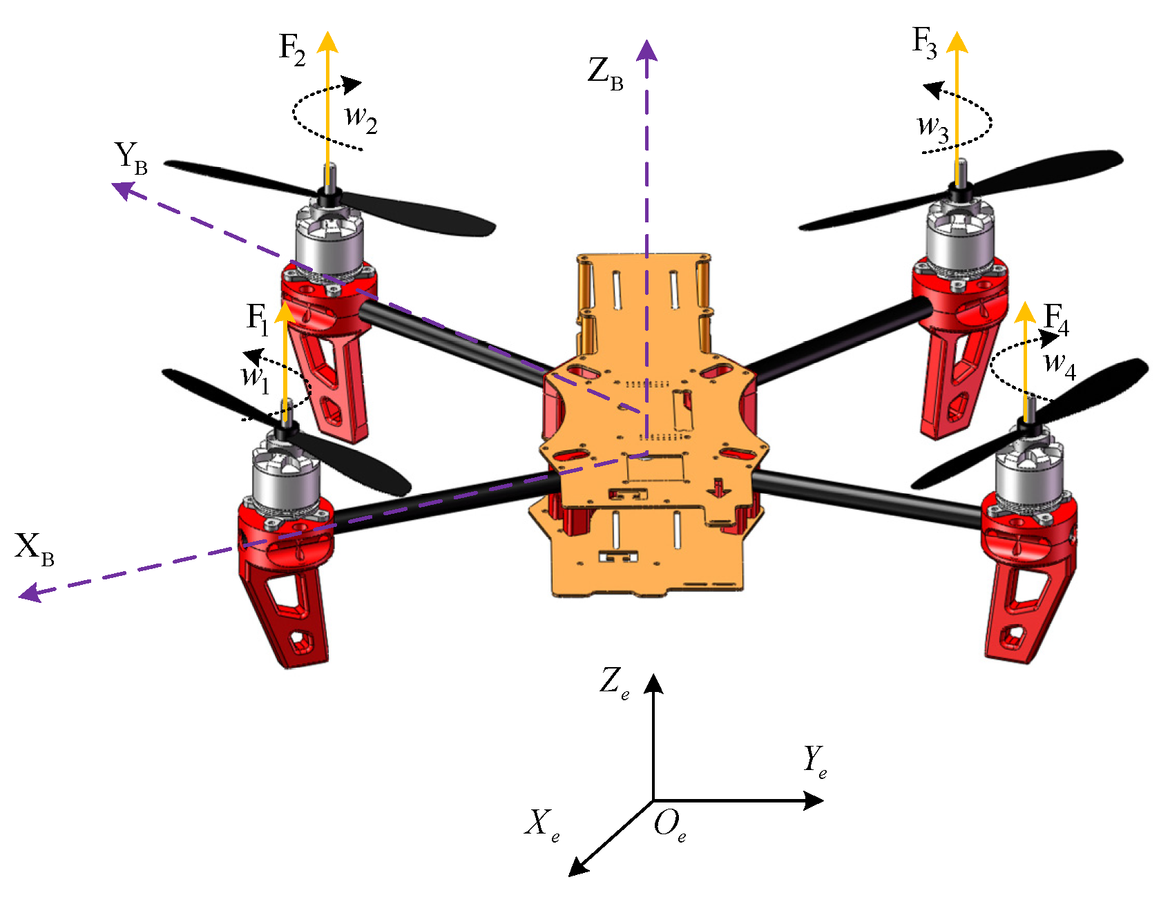
Assuming the quadrotor UAV is a rigid body with its geometric center coinciding with its center of mass and disregarding air resistance, we established an inertial coordinate system , along with a body coordinate system . The structural schematic diagram of the quadrotor UAV is shown in Figure 1, among them, the upward orange arrow represents the aircraft’s airframe coordinate system, and the left purple arrow represents the navigation coordinate system. The lift forces generated by the four rotors of the UAV are denoted as .
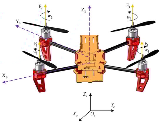
Figure 1.
Schematic diagram of the structure of the quadrotor UAV.
Let and represent the position vector and velocity vector in the inertial coordinate system, respectively. Similarly, and represent the angular velocity vector and the velocity vector in the body coordinate system, respectively. , where represent the three attitude angles of the quadrotor: roll angle, pitch angle, and yaw angle, respectively.
It is evident that the relationship between and can be expressed as follows:
Furthermore, and are related by the following equation:
where
Here, denotes and denotes .
The relationship between can be described as follows:
where
In the context of quadrotor UAVs, the Newton–Euler equations yield the following:
where
Here, , and represent the moments of inertia of the quadrotor UAV around the , and axes of the body coordinate system, respectively; and denote the resultant external force and torque acting on the quadrotor UAV, respectively.
The resultant external forces and torques can be calculated as follows:
where represents the mass of the quadrotor UAV; is the acceleration due to gravity; is the total lift generated by the four propellers on the aircraft; is the air resistance torque vector; is the torque vector generated by the four propellers; and is the gyroscopic torque vector produced by the four propellers.
The total lift, , generated by the four propellers is calculated as follows:
where is the lift produced by the th propeller and
with indicating the rotational speed of the propeller and representing the lift coefficient of the propeller.
The air resistance forces , , in the inertial coordinate system, acting along the three axes, are assumed to be proportional to their respective velocities, leading to the following:
The coefficients correspond to the air resistance factors, which naturally vary with the drone’s orientation. For minor attitude adjustments in the drone, these variations are relatively small. To simplify the analysis, it is generally assumed that these coefficients remain constant.
The air resistance torque vector, , is calculated as follows:
where , and represent the air resistance torques in the body coordinate system of the quadrotor UAV, acting along the three axes. It is assumed that their magnitudes are directly proportional to the corresponding angular velocities, which leads to the following:
Here, denotes the respective air resistance torque coefficients.
The torque vector, , generated by the four rotors of the UAV is calculated as follows:
where represents the roll torque generated by the difference in lift between the left and right propellers; is the pitch torque generated by the difference in lift between the front and back propellers; and is the yaw torque generated by the difference in the twisting torques of the clockwise and counter-clockwise rotating propellers.
The calculations for , , , and are as follows:
where is the distance from the propeller shaft to the UAV center of mass, and is the propeller’s drag coefficient.
The gyroscopic torque vector, , generated by the four rotors is calculated as follows:
where
and is the moment of inertia of the propellers.
The mathematical expression for actuator failure in the quadrotor UAV is as follows:
where ; ; and represent the actual control inputs under normal operation and in the event of a failure, respectively; denotes the actuator failure factor; and indicates a constant bias fault. Based on the values of and , various failure scenarios for the actuators are generated.
When the drone is in motion, and the pitch and roll angles are small, it can be approximated that , , , .
Therefore, the dynamics model of the quadrotor UAV with actuator failures and external disturbances can be represented as follows:
where denotes the disturbances from the external environment.
3. Consider the Controller Design with Parameter Uncertainty and an Upper-Bound Unknown External Disturbance Under Actuator Failure
Considering the controller design under actuator failures with parameter uncertainties and the unknown upper bounds of external disturbances, to facilitate subsequent analysis, the total sum of external disturbances and actuator bias faults in the dynamics model (Equation (20)) of the quadrotor UAV is redefined. Let , , , , , and . For the design of the controller, the following assumptions are introduced.
Assumption 1.
The redefined disturbances are uniform and bounded, i.e., , , , , , where are known constants.
Assumption 2.
To prevent singularities in the controller, it is set as follows:
3.1. Attitude Controller Design and Stability Analysis
For the successful execution of attitude target trajectory tracking tasks, it is essential to maintain the attitude error within a specified range to achieve the desired attitude target trajectory.
The attitude tracking error is defined as follows:
where the attitude tracking error , represents the actual attitude angles, and denotes the desired values.
The sliding surface is selected as the following:
where . Taking the roll angle as an example, the tracking error is defined as the following:
Hence, the sliding surface is chosen as follows:
Derivation yields are the following:
where . Therefore, the attitude controller is designed as follows:
Within this context, and are known positive constants; is the estimated value of ; and the hyperbolic tangent function is utilized to replace the sign function to mitigate the chattering of the sliding mode control. It is defined as follows:
where , and the magnitude of determines the rate of change at the inflection point of the hyperbolic tangent smooth function.
The adaptive laws for parameters and are designed as follows:
where and are known positive constants.
Considering Assumption 1 for the roll angle dynamics model of the quadrotor UAV, that is Equation (21), if the roll angle controller and parameter adaptive laws are designed as per Equation (30) and assuming Assumptions 1–2 hold, then the attitude tracking error of the closed-loop system will asymptotically converge, such that as .
Proof (Assumptions 1–2).
The designed is stable. The Lyapunov function is selected as follows:
where is the estimation error of , and is the estimation error of . The equation below follows:
The right-hand side of the above equation’s first term is the following:
Then,
Given that , and , then
Substituting the adaptive law of Equations (30) and (34) into Equation (36) and using yields the following:
Considering the definitions of and , and simplifying Equation (37) leads to the following:
Based on the Lyapunov stability criterion, it is deduced that the designed controller is stable. This concludes the proof.
Similarly, the controllers and their adaptive laws for the pitch and yaw angles can be derived as follows:
□
3.2. Position Controller Design and Stability Analysis
From the quadrotor UAV model (21), virtual control inputs are derived as follows:
The tracking errors for positions and are defined as follows:
where , the desired position is and the actual position is .
The sliding surface is designed as follows:
where , and derivation yields the following:
with representing known positive constants. Based on, Assumption 1 the position controller and adaptive laws are designed as follows:
From the virtual control inputs (41), we can derive the following:
where is the desired pitch angle; is the desired roll angle; and is the desired yaw angle.
Based on the above, the overall control diagram of the quadrotor UAV is illustrated in Figure 2. As shown in Figure 2, this scheme adopts a dual-loop control architecture. The position loop (outer loop) receives the desired trajectory (, , ) and generates the virtual control quantities (, , ), which are then solved through Equations (48) and (49) to obtain the attitude angle commands (, ). The attitude loop (inner loop) generates the motor control quantities (, , ) via the adaptive sliding mode controller (RASMC). The parameter estimation module updates the parameter values in real time and feeds them back to the controller, forming a closed-loop adaptive mechanism.
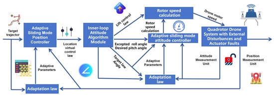
Figure 2.
Four-rotor UAV control structure diagram.
4. Simulation Results Analysis
In this section, simulation and experimental results for the NRASMC (nonlinear robust adaptive sliding mode control), ADRC (active disturbance rejection control), and LQR (Linear Quadratic Regulator) algorithms are presented and discussed. The parameters related to the quadrotor UAV dynamics model are as follows: , , , are all 0.02 , and the gyroscopic effect factor coefficients
The selected controller parameters are as follows:
The desired values for the quadrotor UAV’s position system are , with the desired yaw angle being .
The quadrotor UAV is subjected to external disturbances at 5 s, defined as , and to actuator failures at 10 s as follows:
4.1. UAV Control Simulation Experiment
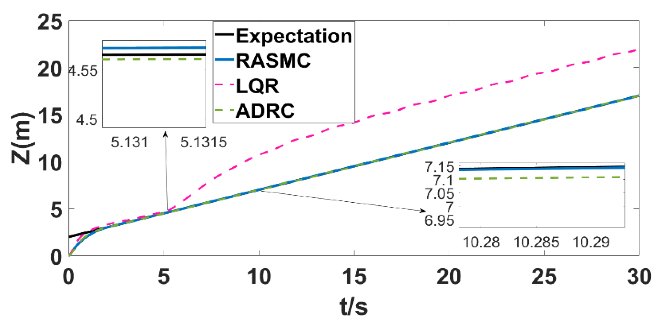
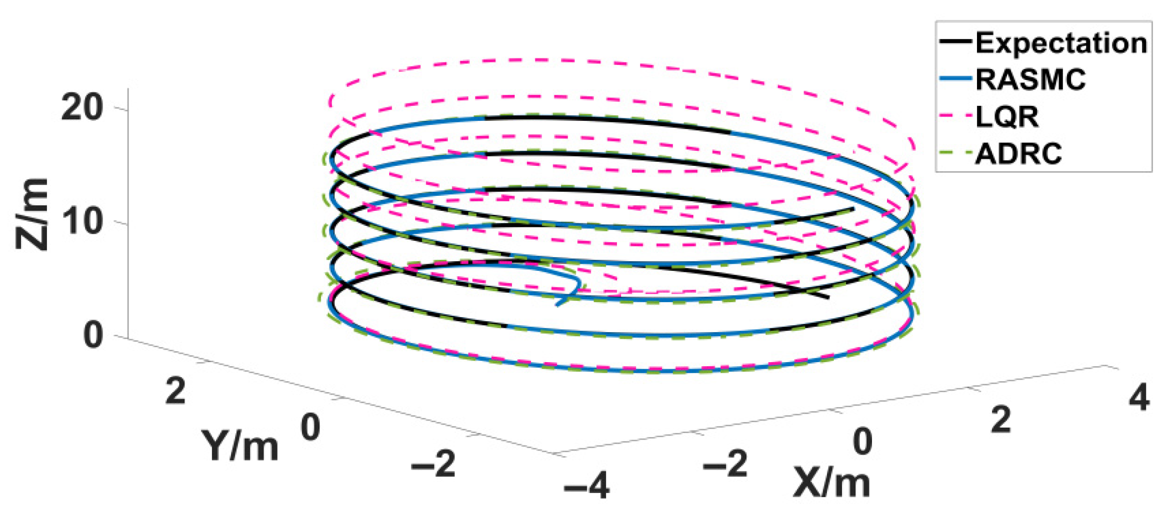
Figure 3 shows the direction tracking track diagram of the positioning system of the four-rotor UAV. At the initial moment, the overshoot of ADRC and LQR is larger, and the tracking error of LQR is obviously larger than that of ADRC. RASMC has smaller overshoot and tracking errors than the first two, and the tracking curve is smooth. When t = 5 s, the system is subjected to external interference; LQR can no longer track the expected trajectory normally, and the tracking error is too large. Although the tracking error of ADRC is smaller than that of LQR, when the system suffers from actuator failure at 10 s, a large tracking error occurs, and the expected value cannot be accurately tracked. RASMC can adapt to compensate for the actuator failure and still track the desired signal accurately, and the tracking effect is significantly better than that of ADRC and LQR, showing strong robustness.

Figure 3.
Position z tracking curves (external disturbance injection at t = 5 s, with an actuator fault occurring at t = 10 s).
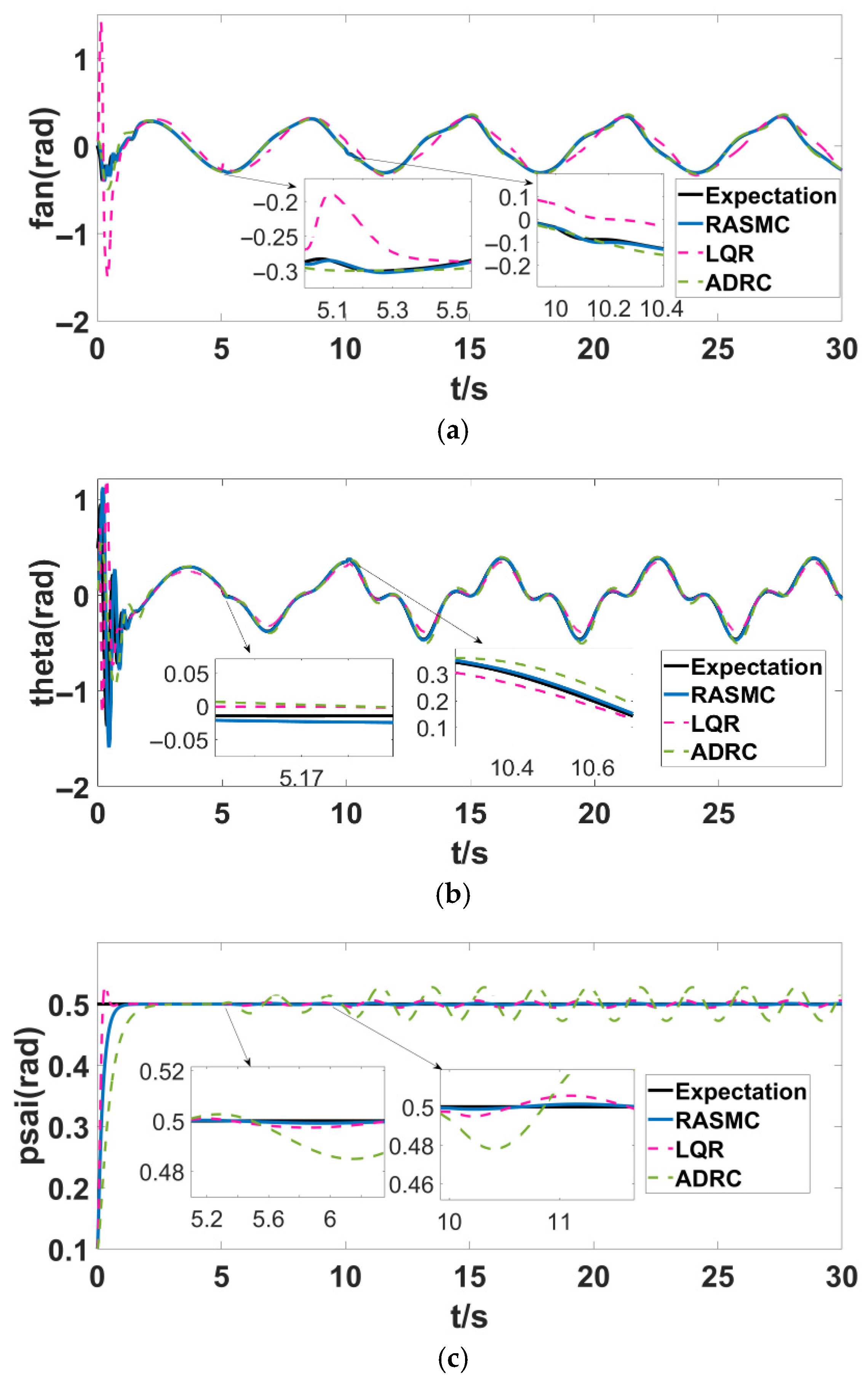
Figure 4, Figure 5, Figure 6, and Figure 7 represent the tracking track diagram and the three-dimensional tracking diagram of the rolling angle, pitch angle, and yaw angle of the attitude system of the four-rotor UAV, respectively. From Figure 4 and Figure 5, it can be clearly seen that LQR oscillation is obvious and ADRC oscillation is smaller than LQR at 0–2 s, but the smoothing of the RASMC tracking curve has faster convergence speeds and smaller tracking errors. When t = 5 s, the system is subjected to external interference, and when t = 10 s, the system is subjected to actuator failure; LQR appears to have obvious oscillation, the tracking error is too large, and the expected signal cannot be tracked. The ADRC is less volatile, but it does not accurately track the desired signal. However, although RASMC has a small oscillation after interference, it can still track the expected signal accurately after adaptive compensation faults and the rapid adjustment of parameters; the tracking curve is smooth, and the error is significantly smaller than LQR and ADRC. It can be seen from Figure 6 that although LQR converges faster at the initial moment, there is an overshoot, while the RASMC tracking curve is smoother. Similarly, when t = 5 s, the system is subject to external interference, and when t = 10 s, the system is subject to actuator failure. LQR and ADRC appear to have obvious oscillations, and the tracking error is too large to track the expected signal. In general, RASMC has the best tracking effect, with strong robustness and accurate tracking performance.
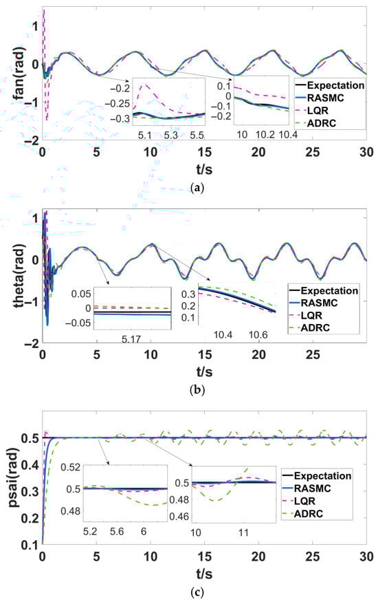
Figure 4.
Attitude tracking curves. (a) Attitude tracking curves; (b) attitude tracking curves; (c) attitude tracking curves.
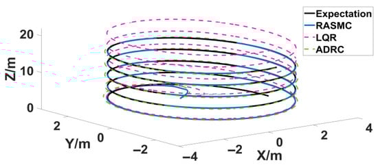
Figure 5.
Three-dimensional trajectory.
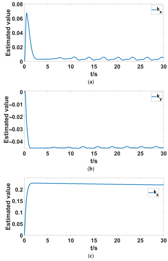
Figure 6.
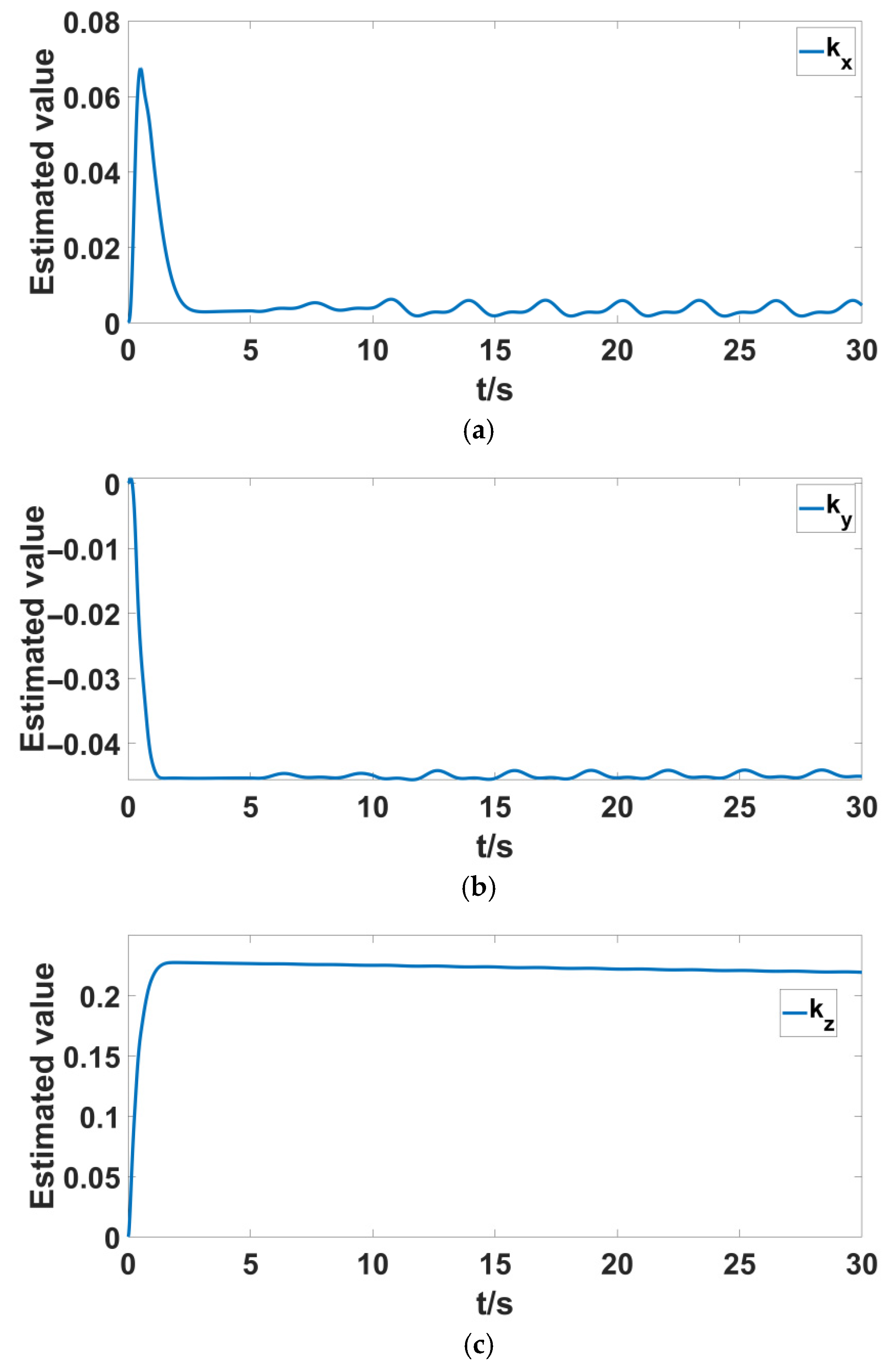
Position system parameter estimation curves. (a) The estimates of system at position ; (b) the estimates of system at position ; (c) the estimates of system at position .
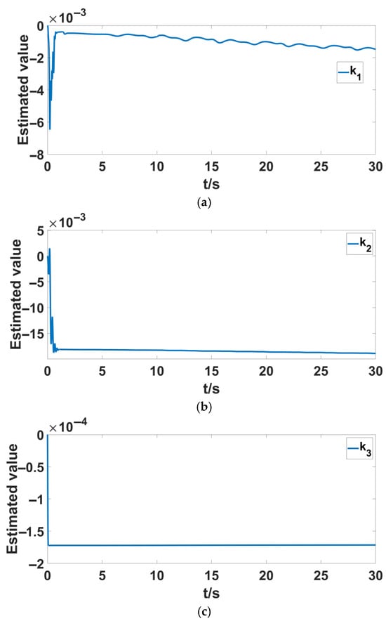
Figure 7.
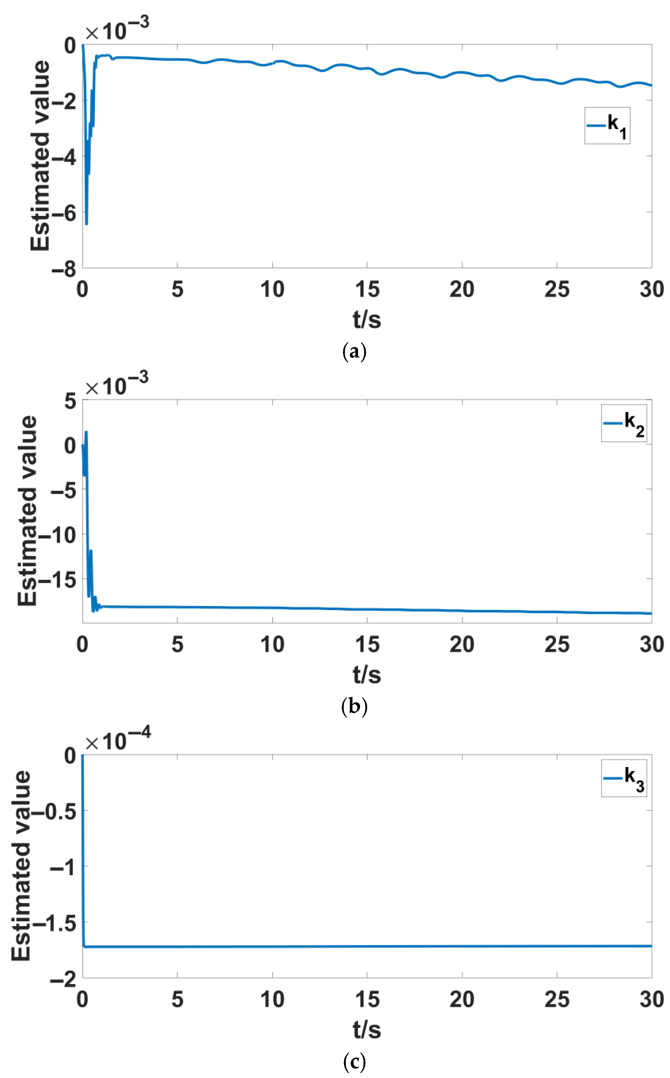
Attitude system parameter estimation curves. (a) The estimates of system at attitude ; (b) the estimates of system at attitude ; (c) the estimates of system at attitude .
Figure 6a–c and Figure 7a–c represent the estimation of the physical parameters in Equation (20) of the quadrotor UAV dynamics model. It is important to note that when using the Lyapunov function to analyze the stability of the quadrotor system, the estimation errors cannot be guaranteed to converge to zero, meaning that the upper bound estimates of the system’s physical parameters may not converge to their true values. Furthermore, when the UAV is subjected to external disturbances at 5 s, as shown in Figure 6a,b, the estimated values of and exhibit slight oscillations but remain close to a constant value within a controllable range.
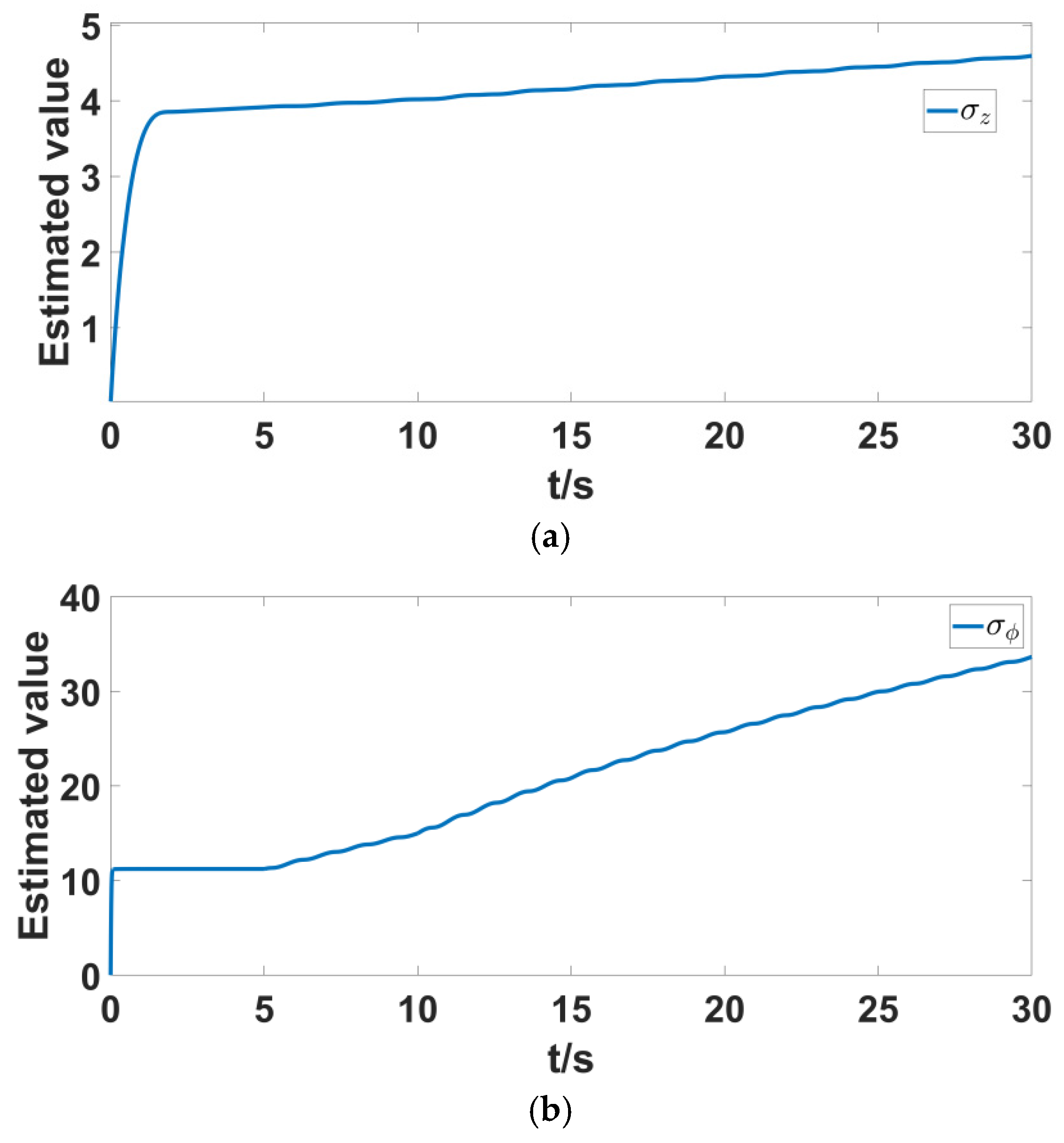
Figure 8a,b represent the estimation of the total disturbance and fault in the z-axis direction position of the quadrotor UAV, as well as the disturbance and fault estimation in the roll angle system of the attitude system. As can be seen from the figures, when the UAV is subjected to external disturbances or faults, the estimated value of the total disturbance automatically increases to a value near a constant, achieving compensation for the total disturbance estimation.
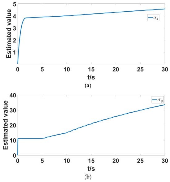
Figure 8.
Lumped perturbation estimation curves of position systems and attitude systems. (a) Estimates total perturbation of the system at position ; (b) estimates total perturbation of the system at attitude .
4.2. Prototype Experiment
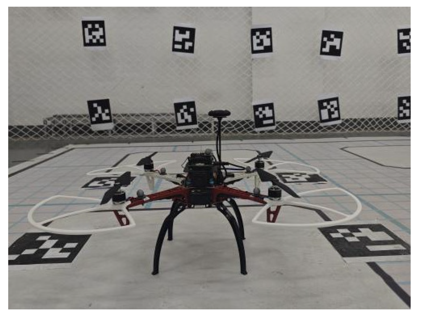
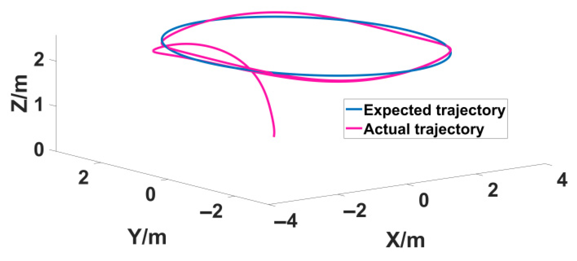
In order to verify the practical feasibility of the controller proposed in this paper, prototype experiments were carried out. For experimental validation, we purchased a DJI F450-4B quadcopter UAV (manufactured by DJI Innovations, originating in Shenzhen, China), and the quadcopter used is shown in Figure 9. It features carbon fiber propellers driven by brushless DC motors, and other detailed descriptions of the DJI F450-4B quadrotor UAV can be found in Reference [35]. The center of the rack is the main controller, and the radar and battery are, respectively, installed on the upper and lower parts of the controller. The expected path of UAV tracking is set as a circular path with a height of 2.5 m and a radius of 1 m. The tracking data and the actual tracking effect are shown in Figure 10.
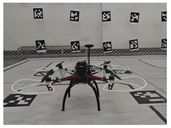
Figure 9.
Prototype quadrotor UAV.
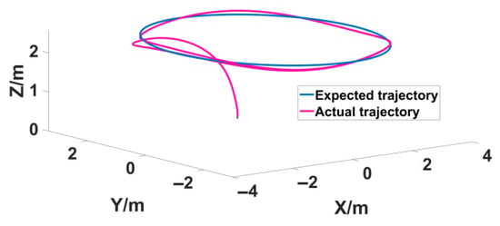
Figure 10.
Quadrotor UAV prototype tracking trajectory.
Prototype testing results (Figure 10) show that, during circular trajectory tracking with a radius of 1 m and a height of 2.5 m, the maximum position deviation is 0.15 m (15% of the trajectory radius). However, when the wind speed exceeds 5 m/s, a periodic oscillation of approximately 0.3 m occurs, indicating that aerodynamic disturbance compensation still needs optimization. Actuator fault injection tests reveal that when the motor efficiency decreases by 30%, the altitude tracking error increases to 0.22 m, which still meets the safe flight threshold (<).
5. Result Discussion
In this study, a robust adaptive sliding mode control (RASMC) framework based on a dual-loop adaptive control is proposed to effectively address the coupling issues of parameter uncertainties, external disturbances, and actuator faults. Via the online estimation of aerodynamic coefficients and disturbance boundaries (with estimation error ≤ ±10%), this method significantly improves trajectory tracking accuracy, reducing the position error to <0.05 m and attitude error to <0.02 rad. Compared to traditional ADRC/LQR methods, the adjustment time is reduced by over 50%, overshoot is decreased by 70%, and the disturbance rejection bandwidth is increased by three times. Additionally, rigorous Lyapunov stability proof ensures the asymptotic stability of the closed-loop system, providing a solid theoretical foundation for practical engineering applications. Prototype experimental results show a maximum deviation of 0.15 m in the 1 m radius circular path tracking (with wind speed <5 m/s), and the real-time control frequency requirements (200 Hz for the attitude loop; 50 Hz for the position loop) are met, validating the engineering feasibility of the proposed method.
However, some limitations of this study have been identified, particularly in strong wind disturbances (>5 m/s), where a periodic oscillation of 0.3 m occurs, indicating the need for further optimization of aerodynamic disturbance compensation. When the motor efficiency decreased by 30%, the altitude error increased to 0.22 m, approaching the safety threshold of 0.3 m, suggesting that the coupling of actuator faults and disturbances still requires more research. To address these issues, future studies should focus on the design of coupled aerodynamic disturbance observers and the optimization of multi-actuator fault isolation strategies to further enhance the system’s disturbance rejection capability and stability, thus promoting the application of this control strategy in complex environments.
6. Conclusions
This paper presents a composite robust fault-tolerant control method based on adaptive sliding mode control (RASMC) and fault estimation aimed at addressing issues such as parameter uncertainty, external disturbances, and actuator failures encountered by quadrotor UAVs in complex flight environments. By designing adaptive laws to estimate unknown parameters and performing stability analysis, this method ensures that the system’s position and attitude tracking errors asymptotically converge to zero. Experimental results show that RASMC outperforms traditional methods (such as ADRC and LQR) in terms of trajectory tracking accuracy, convergence speed, disturbance rejection, and fault tolerance, especially in the presence of external disturbances and actuator failures, where it can precisely track the desired trajectory and maintain small attitude errors. Furthermore, a dual-loop composite adaptive law was employed to achieve the online estimation of system parameters and disturbance/fault bounds, effectively enhancing the system’s robustness and fault tolerance. Additionally, precise control outputs were achieved through virtual control and attitude decoupling. Preliminary flight experiments validate the feasibility of the proposed control framework on actual hardware platforms, demonstrating its potential for the successful transition from simulation to application.
However, to simplify the calculation, this paper treats the external disturbances and actuator faults affecting the UAV as lumped disturbances without considering the coupling between the actuators, which is a significant limitation of this work. Future research should focus on fault-tolerant control based on fault observers, aiming to better account for the coupling between disturbances and actuator faults, thereby enhancing the system’s robustness and ensuring that the UAV can complete flight missions stably.
Author Contributions
Investigation and Methodology, Y.W.; Writing—Review and Editing, Y.W., G.L. and Y.S.; Investigation and Editing, Y.W., G.L., and Y.S. All authors have read and agreed to the published version of the manuscript.
Funding
This research was funded by the Scientific and Technological Project of Gansu Province (24CXGA042) and the University Student Innovation and Entrepreneurship Training Plan Project (202410731067).
Data Availability Statement
All data are included in this paper.
Conflicts of Interest
The authors declare no conflicts of interest.
References
- Biskin, B.; Fliege, J.; Martinez-Sykora, A. Autonomous navigation of unmanned aerial vehicles (UAVs) for border patrolling: A stochastic framework. IMA J. Manag. Math. 2025, 36, dpae033. [Google Scholar] [CrossRef]
- Zhao, S.; Xia, Y.; Ma, L.; Yang, H. Finite-time height control of quadrotor UAVs. Appl. Sci. 2023, 13, 7914. [Google Scholar] [CrossRef]
- Gong, R.; Gong, H.; Hong, L.; Li, T.; Xiang, C. A novel marine predator algorithm for path planning of UAVs. J. Supercomput. 2025, 81, 518. [Google Scholar] [CrossRef]
- Wang, Y.; Feng, X.; Li, F.; Xian, Q.; Jia, Z.H.; Du, Z.; Liu, C. Lightweight visual localization algorithm for UAVs. Sci. Rep. 2025, 15, 6069. [Google Scholar] [CrossRef] [PubMed]
- Luo, J.; Tian, Y.; Wang, Z. Research on unmanned aerial vehicle path planning. Drones 2024, 8, 51. [Google Scholar] [CrossRef]
- He, W.; Zhang, S. Dynamics of a Rigid-flexible Coupling System for Tethered Unmanned Aerial Vehicle with Active Control. IEEE Aerosp. Electron. Syst. Mag. 2025; early access. [Google Scholar] [CrossRef]
- Hua, M.D.; Hamel, T.; Morin, P.; Samson, C. A control approach for thrust-propelled underactuated vehicles and its application to VTOL drones. IEEE Trans. Autom. Control 2009, 54, 1837–1853. [Google Scholar]
- Abdi, S.B.; Debilou, A.; Guettal, L.; Guergazi, A. Robust trajectory tracking control of a quadrotor under external disturbances and dynamic parameter uncertainties using a hybrid P-PID controller tuned with ant colony optimization. Aerosp. Sci. Technol. 2025, 160, 110053. [Google Scholar] [CrossRef]
- Niu, B.; Wang, Y.; Liu, J.; Yue, G.X.G. Path planning for unmanned aerial vehicles in complex environment based on an improved continuous ant colony optimisation. Comput. Electr. Eng. 2025, 123, 110034. [Google Scholar] [CrossRef]
- Nguyen, D.V.; Zhao, H.; Giang, L.N.; Van Thuan, S.; Hu, J. A Dual Adaptive Control Strategy for Quadrotor UAVs Under Model Uncertainties and External Sensor Disturbances. J. Electr. Eng. Technol. 2025, 20, 1775–1788. [Google Scholar] [CrossRef]
- Zhang, X.; Fan, C.; Fang, J.; Xu, S.; Du, J. Tracking prediction to avoid obstacle path of agricultural unmanned aerial vehicle based on particle filter. Proc. Inst. Mech. Eng. Part I J. Syst. Control Eng. 2018, 232, 408–416. [Google Scholar] [CrossRef]
- Kaba, A.; Ermeydan, A. Improved particle filter-based estimation of a quadrotor subjected to uncertainties. Aircr. Eng. Aerosp. Technol. 2022, 94, 1144–1156. [Google Scholar] [CrossRef]
- Zou, Y.; Zhu, B. Adaptive trajectory tracking controller for quadrotor systems subject to parametric uncertainties. J. Frankl. Inst. 2017, 354, 6724–6746. [Google Scholar] [CrossRef]
- Vera Vaca, C.V.; Di Gennaro, S.; Vaca García, C.C.; Acosta Lúa, C. Robust Nonlinear Control with Estimation of Disturbances and Parameter Uncertainties for UAVs and Integrated Brushless DC Motors. Drones 2024, 8, 447. [Google Scholar] [CrossRef]
- Cavus, M.; Allahham, A.; Adhikari, K.; Zangiabadia, M.; Giaouris, D. Control of Microgrids using an Enhanced Model Predictive Controller. In Proceedings of the 11th International Conference on Power Electronics, Machines and Drives, PEMD 2022, Newcastle, UK, 21–23 June 2022; pp. 660–665. [Google Scholar]
- Mofid, O.; Mobayen, S.; Fekih, A. Adaptive integral-type terminal sliding mode control for unmanned aerial vehicle under model uncertainties and external disturbances. IEEE Access 2021, 9, 53255–53265. [Google Scholar] [CrossRef]
- Singha, A.; Ray, A.K.; Govil, M.C. Adaptive neural network based quadrotor UAV formation control under external dis-turbances. Aerosp. Sci. Technol. 2024, 155, 109608. [Google Scholar] [CrossRef]
- Dou, L.; Su, X.; Zhao, X.; Zong, Q.; He, L. Robust tracking control of quadrotor via on-policy adaptive dynamic programming. Int. J. Robust Nonlinear Control 2021, 31, 2509–2525. [Google Scholar] [CrossRef]
- Yang, S.; Yu, F.; Liu, H.; Ma, H.; Zhang, H. Adaptive-Dynamic-Programming-Based Robust Control for a Quadrotor UAV with External Disturbances and Parameter Uncertainties. Appl. Sci. 2023, 13, 12672. [Google Scholar] [CrossRef]
- Wang, F.; Gao, H.; Wang, K.; Zhou, C.; Zong, Q.; Hua, C. Disturbance observer-based finite-time control design for a quadrotor UAV with external disturbance. IEEE Trans. Aerosp. Electron. Syst. 2020, 57, 834–847. [Google Scholar] [CrossRef]
- Huang, T.; Li, T. Attitude tracking control of a quadrotor UAV subject to external disturbance with L 2 performance. Nonlinear Dyn. 2023, 111, 10183–10200. [Google Scholar] [CrossRef]
- Zhang, C.; Zhang, G.; Dong, Q. Adaptive dynamic programming-based adaptive-gain sliding mode tracking control for fixed-wing unmanned aerial vehicle with disturbances. Int. J. Robust Nonlinear Control 2023, 33, 1065–1097. [Google Scholar] [CrossRef]
- Mehmood, Y.; Aslam, J.; Ullah, N.; Chowdhury, M.S.; Techato, K.; Alzaed, A.N. Adaptive robust trajectory tracking control of multiple quad-rotor UAVs with parametric uncertainties and disturbances. Sensors 2021, 21, 2401. [Google Scholar] [CrossRef]
- Bao, C.; Guo, Y.; Luo, L.; Su, G. Design of a fixed-wing UAV controller based on adaptive backstepping sliding mode control method. IEEE Access 2021, 9, 157825–157841. [Google Scholar] [CrossRef]
- Imran, I.H.; Alyazidi, N.M.; Eltayeb, A.; Ahmed, G. Robust adaptive fault-tolerant control of quadrotor unmanned aerial vehicles. Mathematics 2024, 12, 1767. [Google Scholar] [CrossRef]
- Labbadi, M.; Cherkaoui, M. Robust adaptive backstepping fast terminal sliding mode controller for uncertain quadrotor UAV. Aerosp. Sci. Technol. 2019, 93, 105306. [Google Scholar] [CrossRef]
- Hou, Y.; Chen, D.; Yang, S. Adaptive robust trajectory tracking controller for a quadrotor UAV with uncertain environment parameters based on backstepping sliding mode method. IEEE Trans. Autom. Sci. Eng. 2023, 22, 4446–4456. [Google Scholar] [CrossRef]
- Lei, B.; Liu, B.; Wang, C. Robust geometric control for a quadrotor UAV with extended Kalman filter estimation. Actuators 2024, 13, 205. [Google Scholar] [CrossRef]
- Lee, W.C.; Lee, K.; Choi, H.L. Multi-modal Neural Adaptive Observer for Sensor and Actuator Fault Detection and Identification. Int. J. Aeronaut. Space Sci. 2024, 26, 1146–1157. [Google Scholar] [CrossRef]
- Zhong, Y.; Zhang, Y.; Zhang, W.; Zuo, J.; Zhan, H. Robust actuator fault detection and diagnosis for a quadrotor UAV with external disturbances. IEEE Access 2018, 6, 48169–48180. [Google Scholar] [CrossRef]
- Okada, K.F.Á.; Morais, A.S.; Ribeiro, L.; Amaral da Luz, C.M.; Tofoli, F.L.; Lima, G.V.; Lopes, L.C.O. Fault-Tolerant Control for Quadcopters Under Actuator and Sensor Faults. Sensors 2024, 24, 7299. [Google Scholar] [CrossRef]
- Liu, H.; Guo, Y.; Zhang, Y.; Jiang, B. Robust fault-tolerant control for quadrotor UAVs with parameter uncertainties and actuator faults. Control Theory Technol. 2024, 22, 581–595. [Google Scholar] [CrossRef]
- Ranjan, S.; Majhi, S. Fixed-Time State Observer-Based Robust Adaptive Neural Fault-Tolerant Control for a Quadrotor Unmanned Aerial Vehicle. Int. J. Adapt. Control Signal Process. 2025, 39, 132–151. [Google Scholar] [CrossRef]
- Wu, Q.; Zhu, Q. Prescribed performance fault-tolerant attitude tracking control for UAV with actuator faults. Drones 2024, 8, 204. [Google Scholar] [CrossRef]
- Salma, N.M.; Osman, K. Modelling and PID control system integration for quadcopter DJIF450 attitude stabilization. Indones. J. Electr. Eng. Comput. Sci. 2020, 19, 1235–1244. [Google Scholar]

Disclaimer/Publisher’s Note: The statements, opinions and data contained in all publications are solely those of the individual author(s) and contributor(s) and not of MDPI and/or the editor(s). MDPI and/or the editor(s) disclaim responsibility for any injury to people or property resulting from any ideas, methods, instructions or products referred to in the content. |
© 2025 by the authors. Licensee MDPI, Basel, Switzerland. This article is an open access article distributed under the terms and conditions of the Creative Commons Attribution (CC BY) license (https://creativecommons.org/licenses/by/4.0/).