1. Introduction
In recent years, due to the large-scale grid connection of intermittent renewable energy such as solar and wind energy in China, the peak shaving capacity of the power system is insufficient, and the pumped-storage unit satisfies this demand of the power system well, thus achieving a leap development [
1]. A pump turbine is the core component of energy conversion in a pumped-storage power station. The goal of the optimal design of a pump turbine is to achieve high efficiency and stability. Pump turbine design is a typical multi-objective optimization design [
2]. The control parameters in the design process include cavitation, efficiency, pressure pulsation, S zone margin, hump zone margin, etc. A list of research results in this area are as follows: Luo et al. reviewed the cavitation phenomenon in hydraulic machinery and pointed out the impact of cavitation on water pump turbines [
3]; Dorfler et al. systematically summarized the pressure pulsation problem caused by flow in hydraulic machinery [
4]; Zhu et al. designed an efficient pump turbine using optimization design theory [
5]; Zhang et al. systematically combed the problem of S zone caused by rotating stall [
6]; Deyou et al. studied the formation mechanism of a hump zone [
7]. The operation of a pump turbine is a coupling of multiple factors. According to the current literature, there are few papers concerning the influence of axial force on the operation of pump turbines. The specific speed of the pump turbine is smaller than that of the conventional Francis turbine, and the upper crown area is larger than the lower ring area. The upper crown clearance of the runner bears high pressure and the lower ring clearance bears low pressure, so the axial hydraulic thrust acts on the runner. Larger axial hydraulic thrust increases the load and friction loss of the thrust bearing, reduces the efficiency of the generator motor, and makes the design of the thrust bearing more difficult. Therefore, in engineering, pressure-balance pipes are generally installed on the upper and lower sides of the runner to reduce the axial hydraulic thrust [
8,
9]. The use of the pressure-balance pipe will cause a certain volume loss of the pump turbine and reduce the efficiency of the pump turbine. At the same time, the pressure pulsation and vibration caused by the flow will cause the pressure-balance pipe to become a hidden danger of flooding the plant. Therefore, studying the optimal design of the pressure-balance pipe and its influence mechanism on the performance of the pump turbine can significantly improve the stability, the safety, and reliability of the pumped-storage power station operation.
Following the development of computational fluid dynamics (CFD) technology, CFD numerical simulation has been widely used in the optimization design and mechanism research of pump turbines. For example, Liu et al. established a multi-objective optimization design method combined with CFD technology. The ultra-high head water pump turbine was optimized [
2], Pavesi et al. applied CFD technology for a numerical simulation of the flow pattern of the variable speed water pump turbine under power-off conditions [
10], Jacquet established a full flow channel model for S area, the internal flow mechanism was studied [
11]. However, none of these research processes has put the pressure-balance pipe into the 3D modeling analysis. Liang et al. established a three-dimensional numerical model and preliminarily explored the influence of the pressure-balance pipe on the flow of the seal clearance and its surroundings [
12] but did not evaluate the effect on the axial force in detail. Qu explained the mixed flow type from the structural aspect, the pressure-balance pipe on the head cover of the turbine, and also proposed several improvement measures [
13] but the mechanism was not involved.
Considering that the main purpose of setting a pressure-balance pipe is to improve the axial hydraulic thrust of a pump turbine, a numerical model of the whole flow channel including a pressure-balance pipe is established for a pump turbine of a pumped-storage power station. The influence of the diameter changes and the position of the pressure-balance pipe on the leakage volume (efficiency) and axial hydraulic thrust is studied by CFD technology, so as to find out the influence of the pressure-balance pipe on the stability of the pump turbine, guiding the optimal design of the pump turbine.
2. Analysis of the Components of Axial Hydraulic Thrust
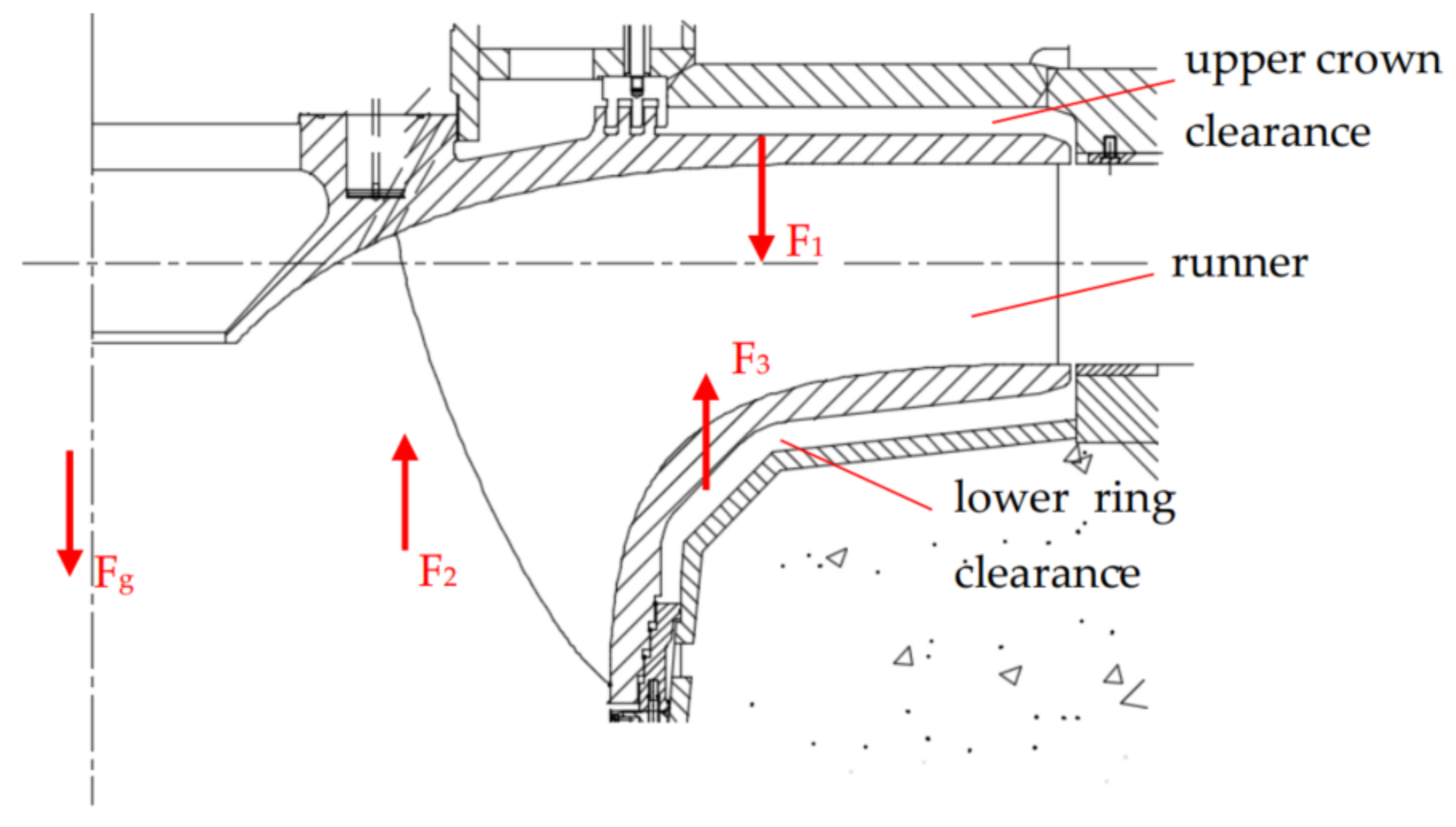
The monitor of axial hydraulic thrust consists of three parts in this paper. The three parts are shown in
Figure 1 (the upward force is positive, vice versa):
F1: the axial hydraulic thrust of the upper crown clearance on the runner surface, the direction is downward;
F2: the axial hydraulic thrust on the runner channel and the surface of blade, the direction is upward on turbine mode;
F3: the axial hydraulic thrust of the lower ring clearance on the runner surface, the direction is upward;
Fg: the gravity of the rotating parts;
F∑: the resultant force of the axial hydraulic thrust on the runner surface, which is equal to the sum of F1, F2 and F3;
Faxial: the resultant force of F∑ and Fg.
Figure 1.
A diagram of the parts of axial hydraulic thrust.
Figure 1.
A diagram of the parts of axial hydraulic thrust.
3. Simulation Model and Adjustment Scheme
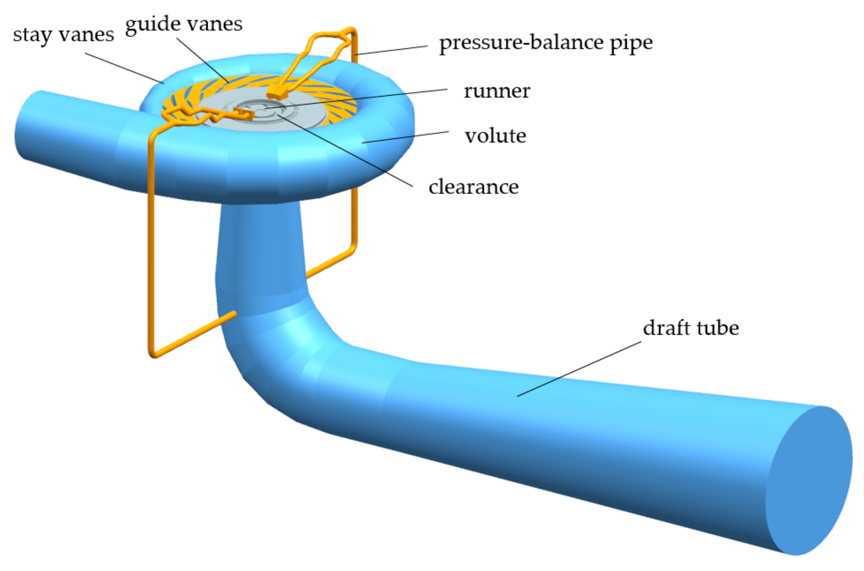
The object of this paper is modeled according to a pumped-storage power station unit. The diameter of the runner is 5.04 m, the number of runner blades is 9, the number of guide vanes and stay vanes is 20, and the rotational speed is 300 rpm. As shown in
Figure 2 and
Figure 3, the flow passage model of a pump turbine includes a volute, stay vanes, guide vanes, runner, draft tube and pressure-balance pipes, as well as the clearance of the runner. The normal water level of the upper stream reservoir of the storage power station is 400 m, and the minimum water level is 376.5 m; the normal water level of the lower stream reservoir is 103.7 m, and the minimum water level is 65 m.
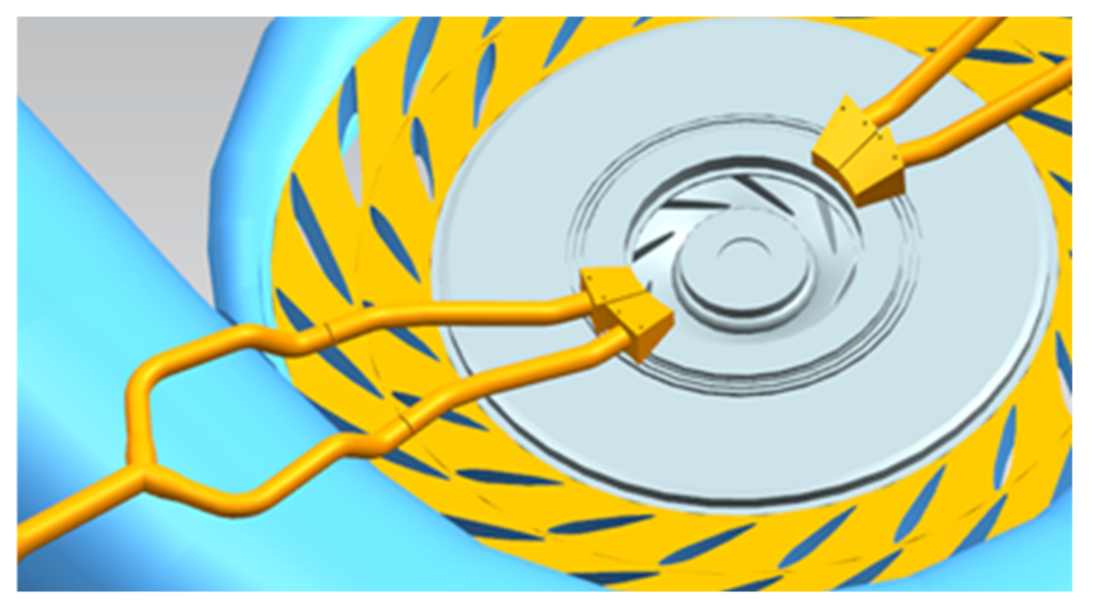
The influence of the changes in the pressure-balance pipe diameter on the axial hydraulic thrust of the runner is studied in this paper. The pressure-balance pipe connects the inner side of the wearing ring and the draft tube; the distribution position of the pressure-balance pipe is shown in
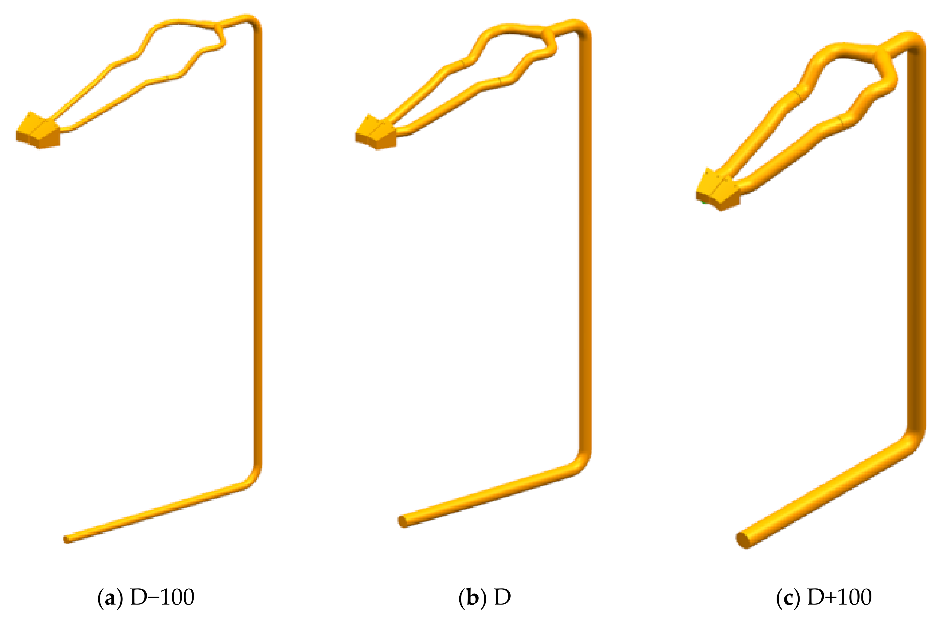
Figure 3. The original pressure-balance pipe diameter in the simulation model is 250 mm, and this model is marked as D. Through discussion with the related technical personnel combined with engineering practice, it was considered reasonable to study the influence of the pipe diameter change on the water thrust force by changing the original pressure equalizing pipe diameter by 100 mm. In this paper, the diameter of the pressure equalizer was increased and decreased by 100 mm, which is denoted as D+100 and D−100, respectively. Specific parameters are shown in
Table 1, and the three-dimensional model is shown in
Figure 4.
In this study, the meshing method is a combination of structured and unstructured grids. ICEM and mesh modules in ANSYS are used to mesh each computing domain. After comprehensively considering grid quality, calculation accuracy, and computing resources, a grid independence verification was conducted, then a grid unit number of about 8 million for calculation was selected for the three models with different pipe diameters, and the grid quality was greater than 0.32. The number and types of grids of model D under 100% load are shown in
Table 2, the grid number of other calculation models is basically the same as for this model.
6. Analysis of Axial Hydraulic Thrust
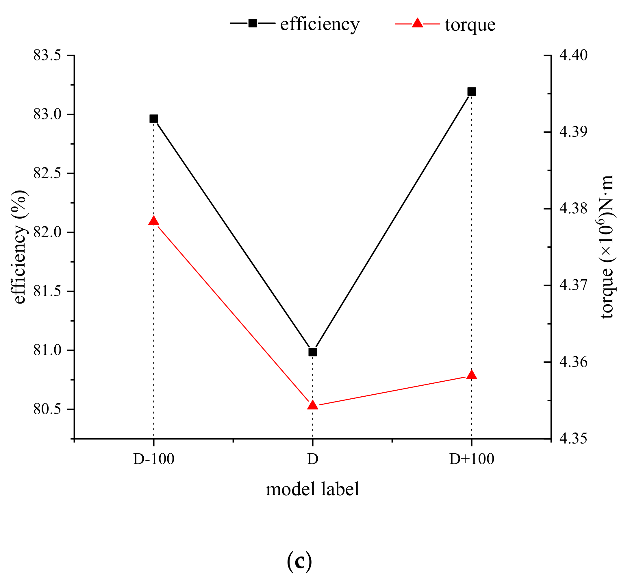
Figure 6 shows the change in the axial hydraulic thrust force (hereinafter referred to as the resultant force) on the runner under different load conditions with the changing of pipe diameter. Under the load conditions of 100% and 75%, the change rule is the same. As the pipe diameter increases, the resultant force increases positively. For the 100% load condition, the resultant force is vertical downward when the pipe diameter of the pressure-balance pipe is reduced, mainly due to the large downward hydraulic thrust generated by the upper crown clearance on the runner. In the simulation with both the original pipe diameter and the increased pipe diameter, the resultant force is vertical upward. For 75% load conditions, the direction of the resultant force is always upward. For the 50% load condition, the directional characteristics of the resultant force are the same as the 100% load condition. When the pipe diameter increases from D−100 to D model, the resultant force increases positively. From D to D+100 model, with the pipe diameter increasing, the resultant force decreases. It can be seen that, under different load conditions of the turbine, the change in the pressure-balance pipe diameter has different effects on the resultant force.
Each component force will be analyzed in detail later. After analyzing the hydraulic thrust component of the runner, it is found that the component force F2 is less affected by the change in the pressure-balance pipe diameter. F2 is mainly affected by the working conditions. As the flow rate increases, F2 also gradually increases. The clearance of the upper crown and the lower ring exerts a decisive influence on the change in the resultant force caused by the axial hydraulic thrust F1 and F3 generated by the runner. Therefore, the following mainly analyzes F1 and F3 under different working conditions.
The variation of force components F
1 and F
3 with the diameter of the pressure-balance pipe is shown in
Figure 7 and
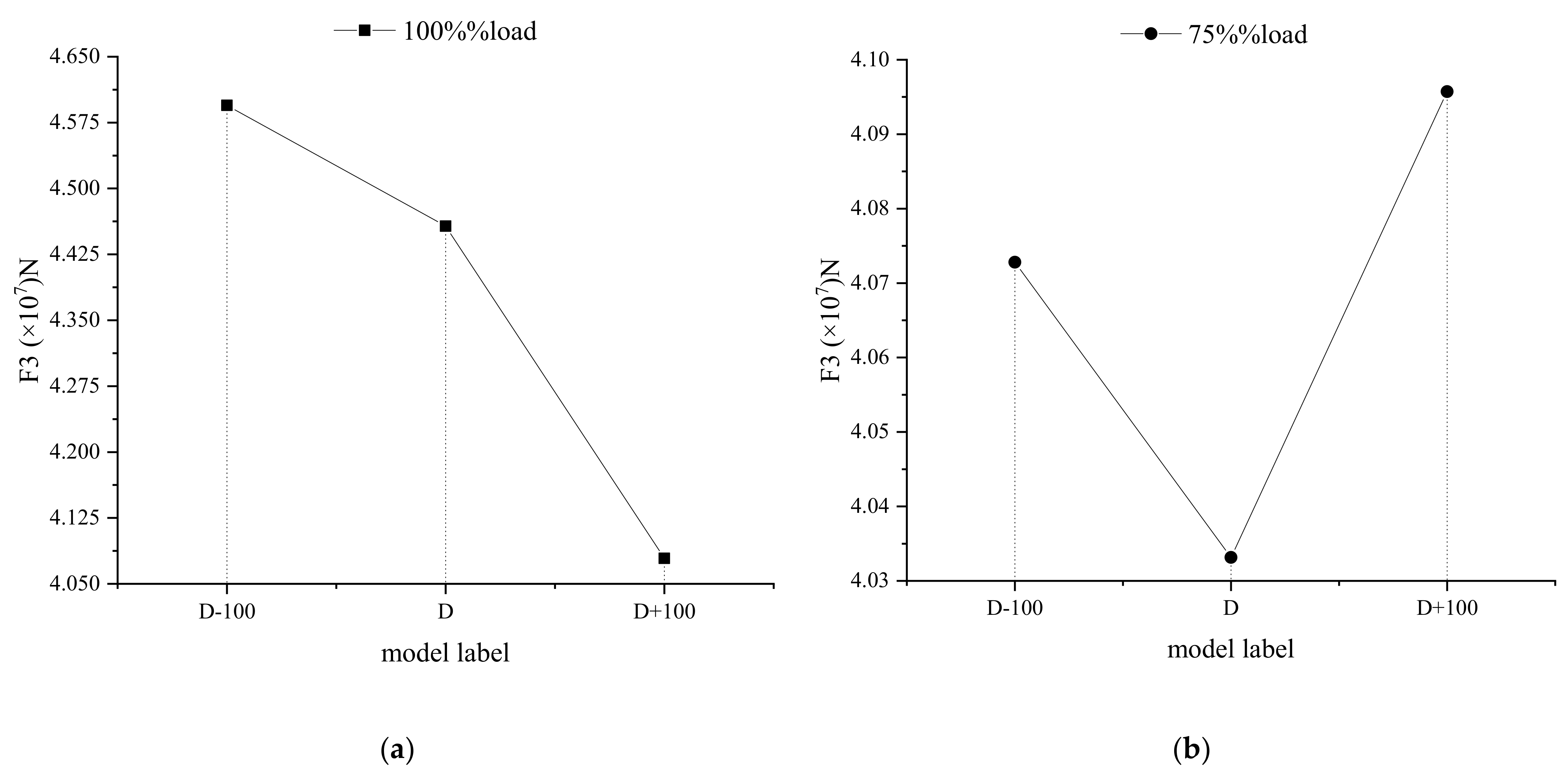
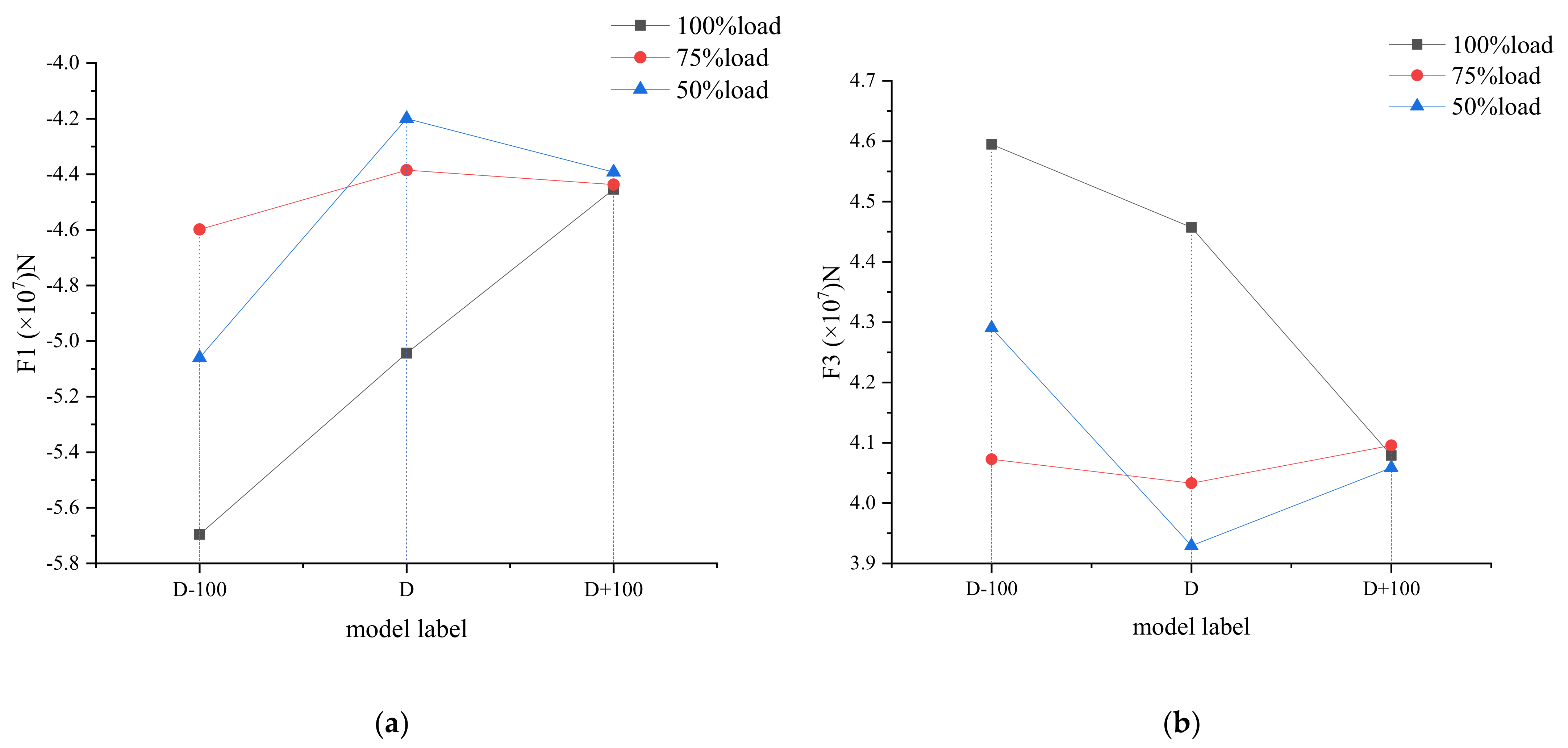
Figure 8. For 100% load condition, the axial hydraulic thrust of upper crown clearance on the runner and lower ring clearance on the runner decreases with the increase in pipe diameter. The resultant force of vertical upward hydraulic thrust increases, which is caused by the decrease in vertical downward hydraulic thrust of upper crown clearance on the runner. The variation amplitude of the hydrodynamic force is larger than that of the lower ring clearance, which has a decisive effect on the variation of the resultant force of the hydrodynamic force. For 75% load condition, the regular variation pattern of resultant force with the diameter of the pressure-balance pipe is consistent with that of 100% load condition; in other words, the regular variation pattern of component force F
1 and F
3 with the diameter of the pressure-balance pipe is consistent with that of 50% load condition. With the diameter of the pressure-balance pipe increasing, component force F
1 and F
3 decrease first and then increase. The variation of axial hydraulic thrust resultant force under 75% load condition is determined by the joint action of F
1 and F
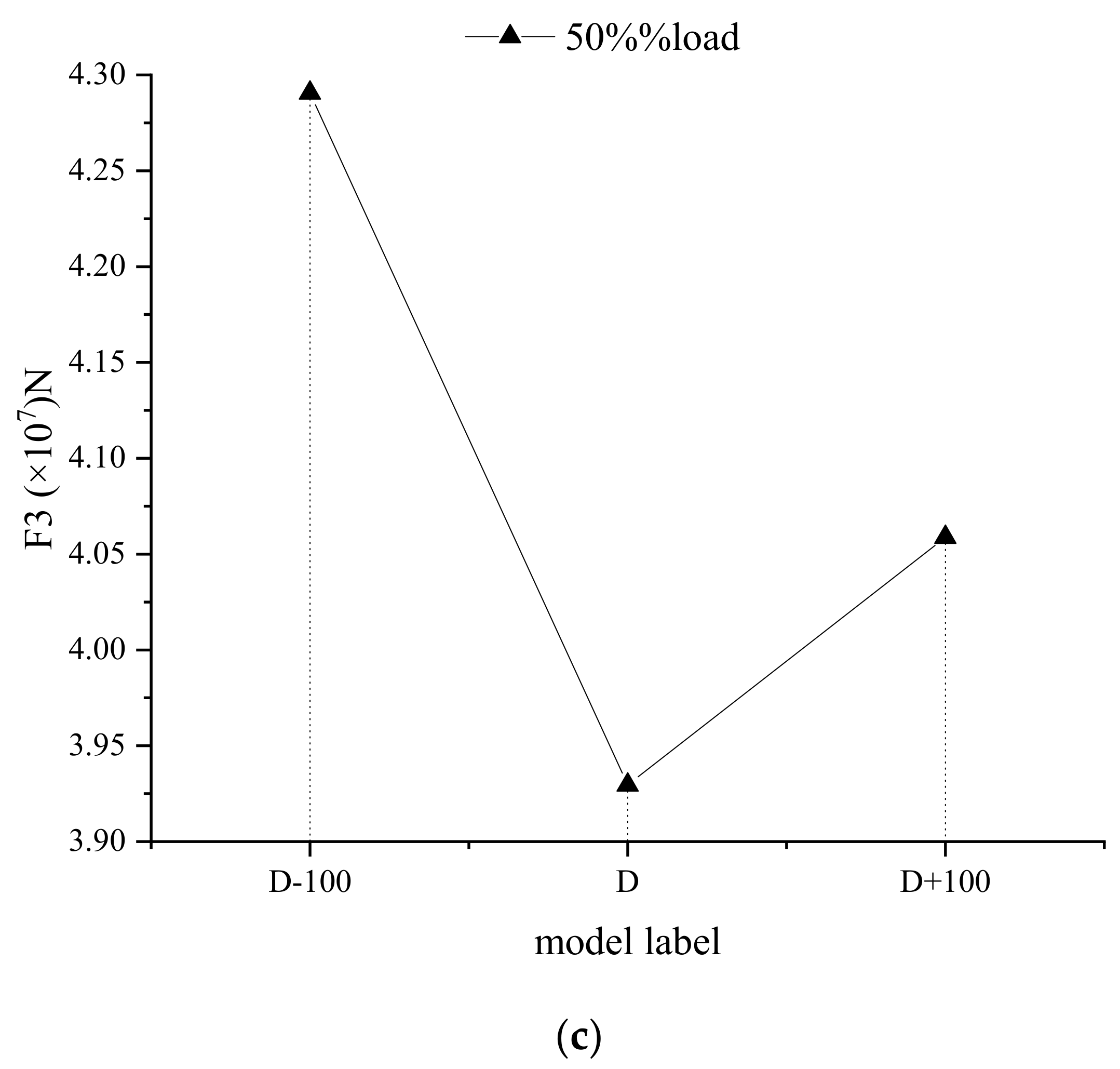
3. For 50% load condition, the change in hydraulic thrust force on the runner with the diameter of the pressure-balance pipe is different from the other two conditions. With the increase in the diameter of the pressure-balance pipe, the axial hydraulic thrust first increases and then decreases in the vertical direction. The regular variation pattern of F
1 and F
3 components with the diameter of the pressure-balance pipe under 50% load condition is the same as that under 75% load condition. The change in upper crown clearance component has a decisive influence on the change in water hydraulic force on the runner.
Figure 9 shows the resultant force of the hydraulic thrust generated by the upper crown and the lower ring. The direction of this force is vertically downwards. The change in the resultant force determines the change trend in the resultant force of the axial hydraulic thrust on the runner, that is, when the pressure-balance pipe diameter changes, it affects the resultant force of the axial water thrust through the influence of the water pressure in the gap between the upper crown clearance and the lower ring clearance. It can be seen that as the diameter of the pressure-balance pipe increases, the combined force of F
1 and F
3 is reduced under 100% load and 75% load conditions, which means that the ability to balance the pressure of the upper and lower clearance of the runner is improved. For the 50% load condition, when the pipe diameter increases on the basis of the design pipe diameter, the combined force of F
1 and F
3 also increases, indicating that the ability of the pressure-balance pipe to balance pressure at this time weakens as the pipe diameter increases.
Under different working load turbine conditions, the comparison of the influence of pipe diameter change on the upper crown and lower ring clearances on the axial hydraulic thrust of runner is shown in
Figure 10. It can be seen from the figure that when the diameter of the pressure-balance pipe decreases, F
1 and F
3 decrease under the three working conditions, while, when the diameter increases, F
1 and F
3 decrease under 100% load condition and F
1 and F
3 increase under 75% and 50% load condition. From the above comparison, it can be concluded that under the conditions of large flow and small flow, i.e., 100% and 50% load, the effect of reducing the diameter of the pressure-balance pipe on the water pressure generated by the upper crown clearance is greater, so the force that has a decisive impact on the change in axial hydraulic thrust is F
1. For 75% load, the effect of changing the diameter of the pressure-balance pipe on the water pressure generated by the upper crown and lower ring is less. Therefore, the change in resultant force is determined by the combined action of F
1 and F
3.
The four interfaces between the pressure-balance pipe (as shown in
Figure 11) and the upper crown clearance and the two interfaces with the draft tube are respectively processed for the average pressure, and the difference is obtained as shown in
Figure 12. It can be seen that under the three different load conditions, as the diameter of the pressure-balance pipe model increases, the pressure difference between the inlet and outlet ends gradually decreases. It can be concluded that when the pressure-balance diameter increases, the pressure difference between the upper crown clearance and the draft tube is reduced.
Considering the gravity of the rotating parts of the unit comprehensively, ignoring the effect of buoyancy to analyzing the axial hydraulic thrust on the runner, the resultant axial hydraulic thrust F
axis obtained under different working conditions is shown in
Figure 13. The resultant force of the axial force did not include the weight of the rotating part of the generator. If the weight of the generator is within 150 t, there is no risk of lifting the machine under the three working conditions of the designed pressure-balance pipe diameter.
It can be seen that when the pressure-balance pipe diameter is reduced, the lifting risk of the unit under the three working conditions is reduced. Under 100% and 75% load conditions, increasing the pipe diameter will increase the risk of unit lifting. However, increasing the pipe diameter under 50% load conditions will reduce the risk of the unit lifting. Therefore, it can be concluded that when the diameter of the pressure-balance pipe is reduced, the effect on different load conditions is the same, and when the pipe diameter is increased, the effect on the hydraulic thrust of the large flow and small flow conditions is different.
7. Conclusions
In this paper, the influence of the change in the diameter of the pressure-balance pipe on the axial hydraulic thrust is studied by numerical simulation of the pump turbine with the upper crown clearance, the lower ring clearance, and the pressure-balance pipe in a pumped-storage power station. The influence of three different diameters of the pressure-balance pipe on the axial hydraulic thrust is analyzed under three different loads of 100%, 75%, and 50%. The results show that when the diameter of the pressure-balance pipe changes, the resultant force of axial hydraulic thrust on the runner is mainly determined by the pressure distribution on the outer surface of the upper crown and lower ring. For 100% and 75% load turbine, with the increase in the diameter of the pressure-balance pipe, the axial hydraulic thrust increases vertically. For 50% load turbine, the axial hydraulic thrust increases vertically first and then decreases with the increase in the diameter of the pressure-balance pipe. For 100% and 50% load cases, the variation of resultant force is determined by the variation of axial hydraulic thrust of upper crown clearance on the runner. For 75% load case, the variation of resultant force is determined by the variation of axial hydraulic thrust of upper crown clearance and lower ring clearance on the runner.
The results show that when the diameter of the pressure-balance pipe decreases, the water pressure produced by the clearance between upper crown and lower ring of 100%, 75% and 50% load turbine condition decreases; when the pipe diameter of the pressure-balance pipe increases, the water pressure produced by the clearance between the upper crown and the lower ring decreases under 100% load condition, and increases under 75% and 50% load condition. Combined with the regular variation pattern of the resultant force, it can be concluded that the variation of the diameter of the pressure-balance pipe mainly affects the hydraulic thrust on the upper crown clearance of the runner, and the variation amplitude of the axial hydraulic thrust on the runner of inner channel and blade surface is small, which has no decisive effect on the hydraulic thrust resultant force. With the increase in working load, the variation in the diameter of the pressure-balance pipe first decreases and then increases. Therefore, under 75% load condition, the resultant force will be affected by the water pressure generated by the clearance between the upper crown and the lower ring.
To sum up, in view of the source of the data, the research on the influence of the change in the pipe diameter on the axial hydraulic thrust is limited. In the following research work, the pump condition and transient condition of the pump turbine can be studied comprehensively. Firstly, the extreme condition of the axial thrust can be obtained. When designing the diameter of a pressure-balance pipe in engineering, the bearing range of axial hydraulic thrust on the runner of the unit is given, and then the axial hydraulic thrust under extreme operating conditions of the unit is checked, so as to avoid excessive load bearing on the frame caused by excessive downward axial hydraulic thrust as well as lifting caused by excessively small downward axial hydraulic thrust. Thus, the diameter of the pressure-balance pipe can be further adjusted to ensure the rationality of design.


