Abstract
In this study, a high-speed planing trimaran hull form is designed, and the effects of different displacements and gravity longitudinal layouts on the performance of the trimaran planing hull in calm water are experimentally investigated in the towing tank of the China Special Vehicle Research Institute. Based on previous work, an innovative inner tunnel appendage hydroflap is mounted in the inner aft tunnel, located 1/8 L from the transom in the longitudinal direction with attack angles of 0° and 4°, respectively. Furthermore, a regular stern flap is mounted on the transom close to the chine. The towing test results show that, as the gravity center moves forward, the high-speed region resistance of the planing trimaran increases and the longitudinal stability is also strengthened. Further, the total resistance of the planing trimaran with a heavier displacement is larger while the average mass resistance declines; i.e., the resistance efficiency is improved. The results also indicate that the inner tunnel hydroflap and stern flap enhance the aft hull hydrodynamic lift and tunnel aerodynamic lift. As a result, mounting aft hull lift enhancement appendages can affect the bottom and inner tunnel pressure distribution and then cause a slight resistance decrease in the low-speed region. The value relationship of resistance between groups of appendages for the attached hull and bare hull is reversed at a speed of about Froude number 3.0. Although the aft hull lift enhancement appendages result in a higher resistance cost in the high-speed region, the longitudinal stability is effectively promoted and the occurrence speed of porpoising results in a delay of 1 to 2 m/s.
1. Introduction
With the continuous advances of hull shapes and propulsion techniques, various kinds of well-designed high-speed hydrodynamic-supported vehicles have crossed the speed threshold of 60 knots per hour, which is almost approaching the takeoff speed of an aviette. Under this circumstance, the effect of aerodynamic lift is non-negligible, and if a well-designed lift surface is attached and exposed in air, it can make full use of the aerodynamic lift generated by high-speed air flow. The aerodynamic lift component supports part of the hull’s weight, overcoming the restraint from the water. The hull designing concept is also known as aerodynamically alleviated marine vehicles (AAMVs) [,]. For instance, the high-speed planing catamaran racing boat is a well-known kind of AAMV, which contains a low aspect ratio tunnel in the middle, and two demihulls along the side as sponsors and enclosure. At an ultra-high speed, the additional aerodynamic forces generated in the tunnel account for a proportion of 30–80% lift component lifting the hull total weight []. Similarly, a high-speed planing trimaran is designed based on a monoplaning hull using this concept. As shown in Figure 1, a trimaran planing hull contains a main hull (considered as a regular monoplaning hull) and two thin demihulls alongside the main hull. The bottom of the connecting bridge is mounted as the aero-lift surface, and the tunnel is shielded with the hulls and connecting bridge.
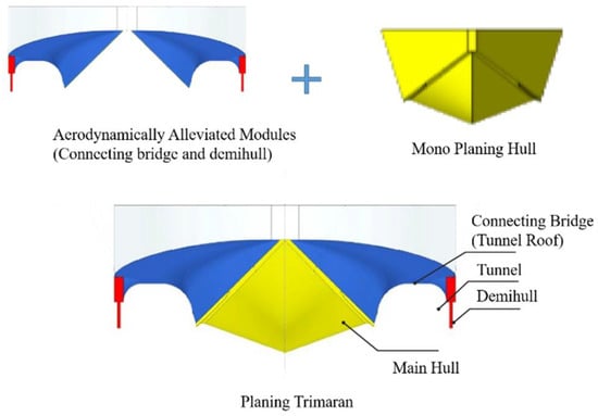
Figure 1.
Designing concept of a planing trimaran and its main elements.
In a high-speed navigation state, the main hull bottom is planing on the water phase, while the air flow, wave making and splash are limited to the region of the tunnel. Thus, the tunnel spatial layout is preliminarily divided into the air phase, water phase and air–liquid mixer []. Meanwhile, due to the introduction of aerodynamic lift, not only the resistance but also the motion oscillation amplitude is buffered and improved []. The additional aerodynamic lift is about 10–20% of the hull total weight. Though the ratio is significant and non-negligible, most of the planing trimaran total weight is still compensated by hydrodynamic lift. The aerodynamic effect is poorer than in the planing catamaran mentioned above []. Therefore, the navigation mechanism of a trimaran is still similar to a conventional planing hull, especially in the high-speed region; i.e., the hull in the high-speed region is confronted with greater resistance and weaker stability [,,].
Several experimental and numerical studies have been conducted focusing on the performance of tunneled planing hulls. Ghassabzadeh et al. numerically simulated the hydrodynamic performance of a multihull tunnel vehicle based on FLUENT software, and the results indicated that the accuracy was acceptable [,]. Chaney introduced a numerical model based on fully unsteady aerodynamic extreme-ground-effect theory and the hydrodynamic added-mass strip theory for tunnel hull vertical plane dynamics in wind gust and wave simulations []. Moghadam et al. discussed and compared the performance between a tunnel hull and its parent monohull based on the k-ε model. The result showed that introducing a tunnel can encourage decreased resistance []. Similarly, Sun et al. carried out a numerical investigation on a stepped monohull and planing trimaran, which shared the same main hull configuration. The results indicate that the coupling effect of the step and demihull has a positive impact on the motion characteristic and longitudinal stability []. Moreover, based on commercial software STAR-CCM+, Roshan et al. numerically simulated the flow field around the hull of a planing trimaran, and the pressure distribution and stream lines in the tunnel were also presented [].
Su Y. et al. numerically investigated the effects of the main dimension of a wave-piercing bow hull on the hydrodynamic performance of a planing trimaran []. Ma et al. have experimentally investigated the influence of displacement and the gravity center on the total resistance and motion behavior. The results also indicated that a tunnel increases aerodynamic lift and obstructs splashing under high-speed motion. Further, appendages (an air jet and bilge keels) were introduced to the model and investigated. The incremental towing test showed that the appendage improved the longitudinal stability while having little effect on the resistance performance [,]. The effect of a tunnel on a planing trimaran’s aerodynamic and hydrodynamic characteristics in the high-speed region were studied by Jiang et al. experimentally and numerically [,]. Zeng et al. and Liu et al. introduced the mathematical motion equations of a trimaran, then introduced a T-foil and a flap and discussed the effects on vertical stabilization control [,]. Lu et al. studied the coupling action of a stern flap and step on a monoplaning hull, both experimentally and numerically []. Sajedi and Ghadimi assumed the wetted surface area as a step height and location function, and by experimental and numerical investigation, the optimal layout and configuration of the step were discussed and extracted with the aim of minimizing the resistance []. Furthermore, a series of towing tests were carried out by Ghadimi et al., analyzing the hydrodynamic performance and effect of appendages such as wedges and steps on resistance and stability performance [,]. For further comparison, previous works related to the current study on planing hulls (especially trimaran) in recent years are presented in Table 1.

Table 1.
Previous studies conducted on monoplaning hulls and planing trimarans. Exp.: experimental; Num.: numerical.
According to the cited works, the pursuit of resistance and stability performance has also become a momentous objective for planing trimaran designers, as has the desire to improve the performance of the monoplaning hull. The planing trimaran carries with it extra concerns regarding the effect of demihulls and tunnels. However, as far as the conducted literature has shown, the appendage technique (e.g., stern flap), which is widely used and a practical and effective strategy for improving the resistance and stability performance of monoplaning hulls, has not yet been fully applied to the planing trimaran. Therefore, the main purpose of the current paper is to study the effects of two kinds of typical appendages (hydroflap and stern flap) on the motion, resistance, and longitudinal stability performance of a planing trimaran. For this purpose, inner tunnel hydroflap and stern flap-mounted planing trimarans are experimentally investigated and the results are analyzed.
The remainder of the current paper is organized as follows: first, the geometric characteristics of the models are described and experimental setup and towing test schemes are presented. Then, the experimental results are discussed and analyzed. Finally, the conclusions are summarized. In addition, the towing test results are shown in Appendix A.
2. Model Description and Experimental Setup
2.1. Geometrical Description and Model Characteristics
In the current study, the planing trimaran is structured with a V-shaped planing main hull and two thin demihulls. Further, the test model is manufactured from glass fiber-reinforced plastics with a geometrical scale factor of λ = 5.625. The total length of the model is 2.4 m. The beam is 0.86 m, while the beam between the main hull chine is 0.448 m. The main hull after the midship is prismatic with a constant deadrise angle of β = 13°. Compared with our previous studies, in order to control the influence factor, no step is introduced to the main hull in longitudinal and transverse directions. The main dimensions and geometry features of the planing trimaran are presented in Table 2, and the body profiles of the full-scale hull and scaled model are depicted in Figure 2.
Table 2.
Principal dimensions of the model.
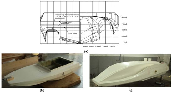
Figure 2.
Different views of the hull and scaled model. (a) A full-scale profile in front view, 0#–4# stand for the first five ship stations numbered 0 to 4 in order; (b) general view of the scaled model; (c) bottom of the scaled model.
2.2. Experimental Setup and Measurements
The current towing test is carried out following the recommendation of the International Towing Tank Conference (ITTC) for high-speed marine vehicle towing testing. The experiments were implemented in the towing tank of the China Special Vehicle Research Institute (i.e., No. 605 Subsidiary Research Institute, Aviation Industry of China Group), located in Jingmen, China. The main dimensions of the towing tank are as follows: a length of 510 m, width of 6.5 m, and depth of 6.8 m. Regarding the towing velocity, the corollary carriage towing system speed ranges from a minimum of 0 m/s to a maximum of 25 m/s, limiting the stable speed error to under 0.1%. The main characteristics of the towing tank are displayed in Table 3, in which the equipment and calibration information is also included. During the towing tests, the model was fixed to the carriage system with two degrees of freedom (pitch and heave). Sensors and devices measuring the heave amplitude, resistance, and pitch angle are mounted on the hull. The details of the experimental setup sketch are shown in Figure 3.
Table 3.
General details of the towing tank.
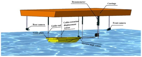
Figure 3.
Details of experimental setup sketch.
During the towing tests, the model was fixed to the carriage system with two degrees of freedom (pitch and heave). Sensors and devices measuring the heave amplitude, resistance, and pitch angle were mounted on the hull. The details of the experimental setup sketch are shown in Figure 3.
Two guide rods were introduced to the longitudinal midline in front and after the model, avoiding transverse motions such as yaw, sway, and roll. To prevent the longitudinal movement interference generated by the towing point during the test, the points were located at the projection point at both broadsides; i.e., the three points were aligned collinearly, with no trim value initially. During the towing process, the towing velocity was measured and controlled constantly by a velocity transducer. The resistance was measured with a resistance dynamometer, which was equipped in the carriage. Regarding measuring the sinkage and trim angle, the sinkage was measured by a cable-extension displacement sensor mounted on the gravity center, while the trim was measured by a foredeck-mounted angle sensor. In addition, in order to monitor and record the motion behavior and wavemaking characteristics visually, two high-speed cameras were attached in front of and after the hull model to film the hull motion and wave patterns during the test process. All the devices and equipment were regularly calibrated.
The hydroflap was designed with a bearing capacity of at least 20 kg of weight under a speed of 12 m/s. The length of the hydroflap was 150 mm, which equaled the width of the tunnel, and the width was designed with a value of 75 mm, setting the aspect ratio to 2 to obtain good hydrodynamic performance. The attack angles were calculated and valued at 0° and 4°. As shown in Figure 4, the hydroflap was mounted in the tunnel, located at 1/8 L from the transom in the longitudinal direction, and a pair of flat stern flaps were introduced and mounted on the main hull aft close to the chine. The stern flaps were mounted in a fixed form along with the main hull planing surface, and an extra angle of 2° was considered []. The main dimensions of the stern flap were as follows: width 100 mm × length 75 mm. The towing test matrix is summarized in Table 4.
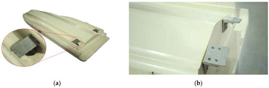
Figure 4.
The installed hydroflap and stern flap at the hull tail. (a) Hydroflap; (b) stern flap.
Table 4.
The schemes of the towing test.
3. Results and Discussion
3.1. Experimental Results, Dimensionless
In the current paper, all cases were carried out with an initial speed ranging from 1 m/s to 17 m/s, and the speed step was 1 m/s; this was performed until the porpoising phenomenon was observed. Parameters such as heave, pitch, and total resistance were recorded correspondingly. Furthermore, the hull wave-making pattern and motion behavior were also filmed by the camera, which gave advantageous auxiliary results for analysis. The processing of the extracted dimensionless test data was as follows:
The non-dimensional towing speed was represented by the volume Froude number, which is defined by the following equation:
where V represents the towing velocity, ∇ indicates the model displacement volume, and g represents the gravity acceleration, at 9.8 m/s2. The resistance non-dimensional processing was processed with a resistance to weight ratio, which was calculated as R/Δ. R is the tested total resistance and Δ is the displacement. Non-dimensional sinkage is defined by the equation
where δexp is the tested sinkage value, while presents a static average draft. The trim angel θ is not processed. In addition, positive values of δ and θ indicate up-pitch and heave, respectively.
In order to improve the readability of the current paper and present the characteristics of each scheme directly with its own scheme code, a nomenclature is used that adheres to the rule of naming all cases with C-XY-Z, where C is short for the word “Case”, X is the symbol of case groups, B represents “bare hull”, H0 represents the “0° attack angle hydroflap”, H4 refers to the “4° attack angle hydroflap”, and S represents a “stern flap”; Y and Z represent the mass and gravity center value. For instance, “C-H090-78” represents scheme case No. 5, in which the hull was mounted with a 0° attack angle hydroflap, the displacement was 90 kg, and the longitudinal center was located 780 mm away from the transom.
3.2. Effects of Longitudinal Position of the Gravity Center
The towing test results were extracted and processed, and Figure 5 plots the total resistance, trim angle, and sinkage of the schemes of the bare hull as functions of the volumetric Froude number Fn. In general, the porpoising of a monoplaning hull often arises at a speed no greater than Fn = 5 [,,,,], while the conversion Froude number exceeded 7 in the current paper; this indicates that the planing trimaran showed excellent high-speed performance.
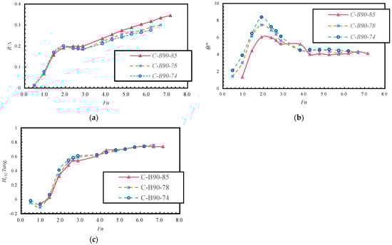
Figure 5.
The effects of the gravity center position on planing trimaran characteristics. (a) Resistance curves; (b) trim angle curves; (c) heave curves.
As is shown in Figure 5a, the resistance curve of the current planing trimaran was similar to the performance of a seaplane in the taking-off phase, which also presents two resistance peaks [], although the humps of the planing trimaran are much more obvious. By comparing the curve trend, it can be seen that the general trends are consistent with each other. In the low-speed region (Fn < 2.0), as the gravity center moves forwards, the resistance decreases. The first resistance hump occurs at a speed of Fn = 1.91. The peak value of C-B90-85 decreased by 5.01% in comparison with C-B90-74, and the value of C-B90-78 is 3.64% compared with C-B90-74. After crossing the first resistance hump area (Fn > 2.0), the resistance consistently increases with the speed. However, the increasing value of the amplitude trend differs from that of the pre-peak; the amplitude increases as the gravity center moves forwards. At the speed of Fn = 7.15, the resistance of C-B90-85 increases by 14.97% compared with that of C-B90-74.
As shown in Figure 5b, the trim trend curve also differs from that of a monoplaning hull. There are still two trim humps, the second peak is not distinct, and the peak value of the second hump is much smaller than the former one. This indicates that the trimaran hull has been up-lifted twice, but the second bow up-lifting phenomenon was not obvious because of the minor differential. The first trim peak is observed at the speed of Fn = 1.91, and when crossing over the speed point, the up-pitch bow gradually falls until the speed reaches Fn = 4.77, at which point the trim angle rises slightly.
The heave in Figure 5c shows that the hull is rapidly lifted up at the beginning (Fn < 3.0), and then the heave amplitude increase trend slows down. The heave over the whole speed range differs little. The heave of C-B90-85 is the minimum in the speed region of Fn < 3.81, and that of C-B90-74 is the maximum. However, the maximum difference between these two schemes is only 0.088; i.e., 16 mm in measured values. The phenomenon is also the reflection of the relationship of the trim angle. When the speed is insufficient to provide aerodynamic and hydrodynamic lift, the trimaran is not vertically lifted up significantly. As a result, the greater the trim angle, the more the gravity center corresponds to a higher vertical gravity center projection value. This also indicates that the effect of the longitudinal gravity center on the planing trimaran heave is not significant, and as it moves forwards, the heave value declines in the low-speed region (Fn < 4.0).
In summary, the forward movement of the gravity center can decrease the trim angle over the whole speed region and decrease the heave value in the speed region of Fn < 4.0. Although moving the gravity center forwards sacrifices the resistance performance, it delays the porpoising speed by 1~2 m/s; i.e., moving the gravity center forwards can strengthen the longitudinal ability of a planing trimaran.
With the screenshot captured by the camera shown in Figure 6, it can be observed that the tunnels along the main hull are initially immersed in water. With the increase in speed, the hull bow is lifted up rapidly in the primary speed region. Within this speed region (0 < Fn < 3.0), the hull is in a hull-borne state and the navigation is in a semi-planing state on the water.
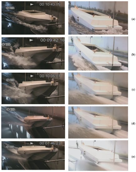
Figure 6.
The screenshot of the towing test of C-B90-85 at different velocities. (a) Fn = 0.95; (b) Fn = 1.91; (c) Fn = 2.38; (d) Fn = 4.77; (e) Fn = 7.15.
The trim angle decrease and sinkage increase are mainly caused by the hydrodynamic lift, as with the monoplaning hull; the planing trimaran hull is lifted up and the tunnel is ventilated gradually. After the tunnel is ventilated (3 < Fn < 5), the hull is further lifted by the tunnel aerodynamic lift, and the trim angle drops down gradually because of the lift moment counteracting parts of the up-pitch moment of the hull. After the speed exceeds a Froude number of 5, the tunnel aerodynamic lift component becomes significant. With the process of the aerodynamic lift-acting center moving to the stern, the trimaran hull is up-lifted and falls for a second time, while the sinkage shows nearly the same trend. As for the wave pattern, wave-making and a light splash spray are generated initially, forming a “chicken wake flow”. With the increase in speed, the “chicken wake flow” extends away from the stern and the wave peak declines, and the splash results in an air–water mixer spray flow, as is obvious in the high-speed region.
3.3. Effects of Hydroflap and Its Mounting Angle
In order to investigate the effects of the hydroflap, the resistance, trim angle, and heave values of the hydroflap group are extracted and plotted in Figure 7. Due to the hydroflap being designed to bear a weight of around 20 kg, the results for the bare hulls weighing 90 kg and 70 kg are all taken into consideration, acting as a marker for comparison.
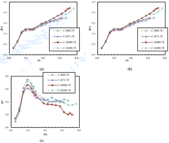
Figure 7.
The effects of the total mass and hydroflap on the planing trimaran’s motion characteristics. (a) Resistance curves; (b) heave curves; (c) trim angle curves.
As expected, increasing the hull mass requires more hydrodynamic and aerodynamic lift to raise the hull up; therefore, the heave value of C-B90-78 is more obviously hysteretic than that of C-B70-78; i.e., at the same speed, the heavier hull corresponds to a smaller heave. The maximum heave between these two cases occurs at the speed of V = 4 m/s, with a difference value of 11.1 mm, and the heave of C-B90-78 id decreased by 38.6 mm on average compared to C-B70-78. The trim angle of C-B70-78 is smaller than that of C-B90-78 over the whole speed region. This is mainly caused by the increase in mass, which provides a greater anti-up-pitch moment to reduce the pitch angle. With the increase in mass, the trim angle increases by an average of 0.64°.
Taking the results of C-H090-78 and C-H490-78 into consideration, introducing a hydroflap does not change the main trend of the planing trimaran in terms of motion behavior, nor the resistance performance. The general performance is still as discussed in section B. The gain resulting from the hydroflap is as follows.
Within in a lower-speed region (0 < Fn < 2.0), the resistances of C-B90-78, C-H090-78, and C-H490-78 are almost identical, with a maximum difference of 0.007. In this region, the vessel is in a hull-borne and semi-planing stage. It seems that a minor hydroflap lift and lift coefficients at lower speed affect the resistance and trim only slightly, while the “minor lift” has relatively obvious effects in lifting up the aft-hull, reflected in the increase in the sinkage value (limited in Fn < 2.0) and lifting up the hull.
With the increase in speed, the lift generated by the hydroflap increases, which provides an increasing moment to counteract the trim angle. As a result, the trim angle of C-H090-78 and C-H490-78 is under that of of C-B90-78 in the rest of the speed region (Fn > 2.0). The minimum and maximum trim differences between C-B90-78 and C-H090-78 occur at the speeds of Froude numbers of 2.86 and 6.19, reaching 0.55° and 1.52°, and the average difference is 0.95°; in contrast, the values for C-H490-78 are Froude numbers of 3.81 and 6.67, trim differences of 0.21° and 0.64°, and an average of 0.41°. In Figure 7b, it can also be seen that the hydroflap decreases the heave value slightly. The main cause of this should be that the hydroflap reduces the trim angle by the lift acting on the aft hull; thus, the gravity center shows a relative decline. Furthermore, the hydroflap may cause the planing surface pressure to be reduced because, in the dynamic equilibrium stage, the hydroflap lift gain reduces the requirements of hydrodynamic lift generated by the planing surface and tunnel aerodynamic lift. The assumption and its specific action mechanism need further investigation in future work.
As a result of the heave and trim angle declining, the wetted surface inevitably increases. In the speed region of Fn > 2.0, the introduction of the hydroflap increases the resistance. Compared with C-B90-78 at a speed of 6.67, the resistances of C-H090-78 and C-H490-78 are magnified by 15.2% and 22.5%. Although the increasing ratio is significant, the differences in values are only 0.0456 and 0.067. Furthermore, the hydroflap can effectively delay the porpoising speed; comparing the results, C-H090-78 delays the porpoising speed point 1 m/s later, while C-H090-78 achieves a level of 2 m/s. Considering the significant porpoising inhibition effect of the hydroflap, a limited resistance sacrifice in the high-speed region is perhaps acceptable in certain circumstances.
3.4. Effects of Stern Flap
In Figure 8, the results of C-B90-78 and C-S090-78 are extracted and plotted as functions of the speed of the volumetric Froude number Fn. At low Froude numbers (0 < Fn < 2), the resistance of C-S090-78, which contains a stern flap, is lower than that of the bare hull C-B90-78. With the increase in speed, after crossing the first resistance hump, the resistance of C-S090-78 exceeds C-B90-78, with the resistance difference amplitude increasing synchronously. At the speed of a Froude number of Fn = 6.67, the resistance increase ratio of C-S090-78 reaches its maximum value of 3.2%. The general trend of how the stern flap affects the resistance is similar to that of the hydro flap.
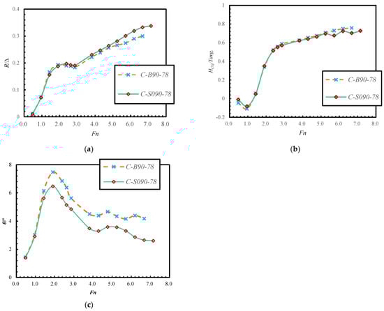
Figure 8.
The effects of a stern flap on the planing trimaran’s motion characteristics. (a) Resistance curves; (b) heave curves; (c) trim angle curves.
As shown in Figure 8c, the trim of C-S090-78 is also smaller than that of C-B90-78. This indicates that the stern flap has a favorable effect on reducing the trim angle. The main cause of this phenomenon may be during navigation: a stern flap with a certain mounting angle diverts the wake flow direction along the flap mounting angle. The stern flap extends the planing surface and virtual length of the hull; i.e., the hydrodynamic lift generated by the main hull increases. Thus, the up-pitch is relieved by the lift and its moment. With the increase in speed, the extra lift generated by the stern flap increases gradually, and the extent of trim reduction increases. At a speed of Fn = 6.67, the trim decreases most, with an angle of 1.92° and a ratio of 45.93%, compared to that of C-B90-78.
The introduction of a stern flap has a slight impact on the trimaran heave value. However, this is not as distinct as that for the hydroflap. However, in the low-speed region (0 < Fn < 3.0), the effect of the stern flap on heave gradually switches from a positive gain to negative, and the critical point for the Froude number is 1.91. In the high-speed region (Fn > 3.0), the increase in heave amplification tends to be stable, and the difference between the two cases is still slight. In the case of C-B90-78, the planing trimaran experiences porpoising at a speed of 14 m/s (Fn = 6.67), while the mounting of the stern flap reduces this to a speed of 15 m/s (Fn = 7.15); i.e., the delaying capacity is 1 m/s. It is obvious that a stern flap can also generate a relatively concentrated stress at the aft hull bottom, which increases the planing surface area, hydrodynamic lift, and trim moment.
Due to the hydrodynamic lift and moment, the hull motion sails much more steadily, and therefore the longitudinal stability is strengthened. Furthermore, the porpoising limit speed point is delayed by 1 m/s.
4. Conclusions
In this paper, an experimental towing test has been conducted; the focus was mainly concentrated on investigating the effects of a longitudinal gravity center layout, hull mass, hydroflap, and stern flap on a planing trimaran’s motion behavior and longitudinal stability. For this purpose, a series of towing test schemes were designed based on the objective parameters and components. The total resistance, heave, and trim angle were measured with acceptable accuracy. According to the towing test results, the effects of the objective parameters on the motion behavior performance and porpoising inhibition were discussed and summarized. Based on the results and analysis presented above, the main conclusions can be drawn as follows:
- The resistance curve of the current planing trimaran presents two resistance peaks. In the low-speed region (Fn < 2.0), as the gravity center moves forwards, the resistance decreases. After crossing the first resistance hump (Fn > 2.0), the resistance trend reverses: as the gravity center moves forwards, the resistance increases.
- The planing trimaran also has two trim humps, and the peak value of the second hump is much smaller than the first one. In addition, in some schemes, the second hump is not distinctly observed. The forward motion of the gravity center can decrease the trim angle over the whole speed region, except for the point of C-B90-85 at a speed of Fn = 3.81.
- The effect of a longitudinal gravity center on the planing trimaran heave is slight and not significant. In view of the absolute value, in the speed region of Fn < 4.0, as the gravity center moves forwards, the heave value declines. However, the trimaran is not actually vertically lifted up significantly. The main cause is the greater trim angle. With a greater trim angle, the vertical projection point of the gravity center rises up, taking the aft hull as the base point. Accordingly, in the speed region of Fn > 4.0, the trim angles of the bare hull groups are almost equal to each other, and the heave variations between different gravity center layouts are also almost equal to each other.
- With the increase in a certain mass, the absolute value of resistance increases. When the speed is in the region of Fn < 3.0, superior resistance is imparted to the heavier planing trimaran. However, once the speed exceeds that value, the resistance relationship reverses, which indicates that a heavier hull possesses a superior unit mass resistance ratio (lower numerical value).
- The increase in hull mass can provide an increase in the anti-up-pitch moment, reducing the pitch angle. More hydrodynamic and aerodynamic lift is also required to lift the hull up. Thus, at the same speed, the lift is limited; i.e., a heavier hull often means a smaller heave.
- A hydroflap provides extra hydrodynamic lift, which generates an increasing moment to counteract the up-pitch moment. Thus, the trim angle of the schemes with a hydroflap is lower than an equal condition bare hull over the whole speed region. For the same reason, the hydroflap lift might redistribute the pressure distribution of the planing trimaran, which would lead to reduced up-lift effects of the bottom and tunnel. Concretely, a 0° attack angle hydroflap reduces the heave value, while increasing the attack angle to 4° compensates the sinkage decrease in the speed region of Fn > 1.0. Before that, the lift generated by the hydroflap is limited, and the heave reduction is therefore covered by lifting effects; i.e., the heave of a hull with a hydroflap is larger.
- Within in a low-speed region (0 < Fn < 3.0), the resistances of the planing trimaran with or without a hydroflap are almost identical: the maximum difference is merely 0.007. With the increase in speed, the heave and trim angle declines, which inevitably leads to wetted surface area expansion. As a result, the introduction of a hydroflap increases the resistance at high speed. With a higher speed, the resistance amplification increases more. However, the attack angle affects the resistance slightly and the resistance curves are almost superposed. The difference between C-H090-78 and C-H490-78 in the speed region of Fn > 6.19 can be attributed to the dramatical fall of the trim angle of C-H090-78, which also reflects and verifies the relationship between trim angle and resistance performance, as mentioned above.
- A stern flap with a certain mounting angle diverts the wake flow extending along the flap, which extends the planing surface and virtual length of the hull. The pressure on the hull bottom is redistributed due to the extra lift generated by the main hull. With the increase in speed, the extra lift generated by the stern flap increases gradually; thus, the up-pitch is relieved by the lift and its moment. Similar to the hydroflap, mounting stern flaps is beneficial to reducing the trim angle over the whole speed region. However, mounting stern flaps affects the heave performance only slightly. A stern flap can improve the resistance performance in the low-speed region Fn < 2.0; when, exceeding the speed point, the resistance relationship reverses, and mounting stern flaps magnifies the total resistance.
- As for the longitudinal stability, moving the gravity center forward and increasing the mass and mounting lift enhancement appendages (hydroflap and stern flaps) can reduce the motion behavior (trim and heave) value, which results in a higher resistance cost in the high-speed region. However, this can effectively promote longitudinal stability performance and delay the porpoising speed point to a level of 1–2 m/s. Considering the significance of porpoising inhibition, a limited resistance sacrifice in the high-speed region is acceptable in certain circumstances.
Author Contributions
Conceptualization, J.Z. and S.L.; methodology, J.Z., S.L. and H.S.; towing test, S.L., L.Z. and J.C.; investigation, S.L. and H.S.; resources, J.Z.; data curation, L.Z. and J.C.; writing—original draft preparation, S.L.; writing—review and editing, H.S. and S.L.; visualization, J.C. and S.L.; supervision, J.Z.; project administration, J.Z.; funding acquisition, J.Z. and H.S. All authors have read and agreed to the published version of the manuscript.
Funding
This work was funded in part by the National Natural Science Foundation of China, grant number 51509055 and 52071100, and in part by the Fundamental Research Funds for the Central Universities, grant number HEUCF180101 and 3072020CF0102.
Institutional Review Board Statement
Not applicable.
Informed Consent Statement
Not applicable.
Data Availability Statement
The data presented in this study are available in Appendix A.
Acknowledgments
The authors would like to thank the crew of the towing tank lab of the China Special Vehicle Research Institute for their help and support during the towing test. Especially, we would like to thank Shengze Shi and Jingjing Ma for their help in writing the test logs and recording test results. Finally, Shijie Lu would like to thank MSc. student Zhuang Li for sharing his constructive suggestions for this paper.
Conflicts of Interest
The authors declare no conflict of interest. The funders had no role in the design of the study; in the collection, analyses, or interpretation of data; in the writing of the manuscript, or in the decision to publish the results.
Appendix A
In this appendix, all obtained experimental results are presented. In the following tables, Xtp presents the distance of towing point in the longitudinal direction from the transom, while Ztp is the height of the towing point from the base line. Tfm is the draft at ship station number 5, while Tam is the draft at ship station number 0.
Table A1.
Parameter setup and experimental results of Case 1.
Table A1.
Parameter setup and experimental results of Case 1.
| Case | No.1 | Δm (kg): 90 | Xgm: 850 mm | Towing point: | Xtp = 850 mm | Tfm: (# 5) 139 mm | Tam: (# 0) 140 mm | |||||||
| Ztp = 251 mm | ||||||||||||||
| Vm (m/s) | 2 | 3 | 4 | 5 | 5.5 | 6 | 8 | 9 | 10 | 11 | 12 | 13 | 14 | 15 |
| Rm (N) | 60.094 | 138.915 | 169.138 | 176.008 | 176.214 | 177.253 | 209.044 | 226.066 | 242.628 | 255.388 | 269.108 | 281.123 | 296.176 | 305.917 |
| h (cm) | −0.78 | 0.39 | 4.48 | 6.67 | 7.95 | 7.55 | 8.49 | 9.59 | 9.69 | 9.88 | 10.2 | 10.39 | 10.32 | 10.32 |
| θ (°) | 1.34 | 4.44 | 6.04 | 5.97 | 5.66 | 5.25 | 5.2 | 4.01 | 4.09 | 3.98 | 4.04 | 4.12 | 4.34 | 4.11 |
Table A2.
Parameter setup and experimental results of Case 2.
Table A2.
Parameter setup and experimental results of Case 2.
| Case | No.2 | Δm (kg): 90 | Xgm: 780 mm | Towing point: | Xtp = 780 mm | Tfm: (# 5) 135 mm | Tam: (# 0) 157 mm | |||||||||
| Ztp = 251 mm | ||||||||||||||||
| Vm (m/s) | 1 | 2 | 3 | 4 | 5 | 5.5 | 6 | 8 | 9 | 10 | 11 | 12 | 13 | 14 | ||
| Rm (N) | 10.486 | 64.847 | 147.578 | 171.578 | 168.364 | 167.257 | 162.562 | 196.892 | 211.229 | 227.389 | 236.082 | 243.138 | 257.162 | 266.041 | ||
| h (cm) | −0.67 | −1.6 | 0.83 | 4.97 | 7.61 | 8.14 | 8.59 | 9.14 | 9.55 | 9.85 | 10.33 | 10.65 | 10.95 | 11.06 | ||
| θ (°) | 1.44 | 3.02 | 6.14 | 7.47 | 6.84 | 6.37 | 5.63 | 4.51 | 4.4 | 4.67 | 4.35 | 4.16 | 4.4 | 4.18 | ||
Table A3.
Parameter setup and experimental results of Case 3.
Table A3.
Parameter setup and experimental results of Case 3.
| Case | No.3 | Δm (kg): 70 | Xgm: 780 mm | Towing point: | Xtp = 780 mm | Tfm: (# 5) 119 mm | Tam: (# 0) 135 mm | |||||||
| Ztp = 251 mm | ||||||||||||||
| Vm (m/s) | 1 | 2 | 3 | 4 | 5 | 5.5 | 6 | 8 | 9 | 10 | 11 | 12 | 12.5 | -- |
| Rm (N) | 7.948 | 53.871 | 111.318 | 127.273 | 130.320 | 132.271 | 138.200 | 167.678 | 177.997 | 189.130 | 199.440 | 207.250 | 212.288 | -- |
| h (cm) | −0.25 | −1.04 | 1 | 6.08 | 8.17 | 8.7 | 9.08 | 9.26 | 9.73 | 10.3 | 10.43 | 10.91 | 10.99 | -- |
| θ (°) | 0.97 | 2.6 | 5.63 | 6.13 | 5.516 | 5 | 4.64 | 4.28 | 4.08 | 4.06 | 4.18 | 4.03 | 3.95 | -- |
Table A4.
Parameter setup and experimental results of Case 4.
Table A4.
Parameter setup and experimental results of Case 4.
| Case | No.4 | Δm (kg): 90 | Xgm: 740 mm | Towing point: | Xtp = 740 mm | Tfm: (# 5) 131 mm | Tam: (# 0) 167 mm | ||||||||
| Ztp = 251 mm | |||||||||||||||
| Vm(m/s) | 1 | 2 | 3 | 4 | 5 | 5.5 | 6 | 8 | 9 | 10 | 11 | 12 | 13 | -- | |
| Rm (N) | 11.133 | 68.963 | 150.655 | 178.066 | 167.492 | 165.689 | 165.463 | 187.356 | 204.408 | 214.875 | 227.576 | 234.857 | 244.510 | -- | |
| h(cm) | −0.25 | −1.04 | 1 | 6.08 | 8.17 | 8.7 | 9.08 | 9.26 | 9.73 | 10.3 | 10.43 | 10.91 | 10.99 | -- | |
| θ (°) | 2.12 | 3.9 | 6.47 | 8.38 | 7.24 | 6.75 | 6.12 | 4.5 | 4.57 | 4.5 | 4.6 | 4.47 | 4.41 | -- | |
Table A5.
Parameter setup and experimental results of Case 5.
Table A5.
Parameter setup and experimental results of Case 5.
| Case No.5 | Δm: 90 kg | Xgm: 780 mm | Towing point: | Xtp = 780 mm | Tfm:: (# 5) 130 mm | Tam: (# 0) 158 mm | ||||||||||||
| Hydroflap attack angle: 0° | Ztp = 251 mm | |||||||||||||||||
| Vm (m/s) | 1 | 2 | 3 | 4 | 5 | 5.5 | 6 | 8 | 9 | 10 | 11 | 12 | 13 | 14 | 14.5 | 15 | ||
| Rm (N) | 12.025 | 67.796 | 140.816 | 168.962 | 172.029 | 170.608 | 176.400 | 216.609 | 229.555 | 245.657 | 263.836 | 282.514 | 301.703 | 326.075 | 340.726 | 348.086 | ||
| h (cm) | −0.09 | −0.92 | 0.59 | 4.57 | 6.81 | 7.24 | 7.58 | 8.29 | 8.98 | 9.48 | 9.43 | 9.49 | 9.65 | 9.95 | 9.71 | 9.69 | ||
| θ (°) | 1.35 | 2.77 | 5.52 | 6.62 | 6.1 | 5.5 | 5.08 | 3.79 | 3.62 | 3.59 | 3.46 | 3.31 | 2.38 | 2.06 | 2.23 | 1.98 | ||
Table A6.
Parameter setup and experimental results of Case 6.
Table A6.
Parameter setup and experimental results of Case 6.
| Case No.6 | Δm: 90 kg | Xgm: 780 mm | Towing point: | Xtp = 780 mm | Tfm: (# 5) 130 mm | Tam: (# 0) 158 mm | ||||||||||||
| Hydroflap attack angle: 4° | Ztp = 251 mm | |||||||||||||||||
| Vm (m/s) | 1 | 2 | 3 | 4 | 5 | 5.5 | 6 | 8 | 9 | 10 | 11 | 12 | 13 | 14 | 15 | 16 | ||
| Rm (N) | 10.163 | 64.406 | 134.113 | 172.911 | 171.647 | 172.068 | 174.783 | 210.014 | 226.743 | 247.381 | 266.354 | 280.466 | 294.490 | 296.626 | 316.599 | 345.734 | ||
| h (cm) | −0.21 | −0.79 | 0.64 | 5.13 | 7.66 | 8.04 | 8.31 | 9.12 | 9.28 | 9.82 | 9.55 | 9.84 | 9.94 | 9.87 | 9.17 | 9.26 | ||
| θ (°) | 1.31 | 2.82 | 5.23 | 7.18 | 6.51 | 6.1 | 5.33 | 4.3 | 3.83 | 4.095 | 4.068 | 3.938 | 3.868 | 3.538 | 3.488 | 3.698 | ||
Table A7.
Parameter setup and experimental results of Case 7.
Table A7.
Parameter setup and experimental results of Case 7.
| Case No.5 | Δm: 90 kg | Xgm: 780 mm | Towing point: | Xtp = 780 mm | Tfm: (# 5) 130 mm | Tam: (# 0) 158 mm | |||||||||||||
| Stern flap mounting angle: 2° | Ztp = 251 mm | ||||||||||||||||||
| Vm (m/s) | 1 | 2 | 3 | 4 | 5 | 5.5 | 6 | 8 | 9 | 10 | 11 | 12 | 13 | 14 | 15 | 16 | |||
| Rm (N) | 9.222 | 63.426 | 138.415 | 166.659 | 175.381 | 170.873 | 169.187 | 204.467 | 219.138 | 234.161 | 249.537 | 267.001 | 283.024 | 294.931 | 299.527 | 345.734 | |||
| h (cm) | −0.14 | −1.14 | 0.7 | 4.89 | 7.2 | 7.73 | 7.99 | 8.7 | 8.96 | 9.29 | 9.74 | 9.47 | 10.13 | 9.84 | 10.18 | 9.26 | |||
| θ (°) | 1.4 | 2.92 | 5.63 | 6.47 | 5.67 | 5.15 | 4.86 | 3.49 | 3.3 | 3.59 | 3.57 | 3.31 | 2.87 | 2.66 | 2.61 | 3.698 | |||
References
- Shipps, P. Hybrid ram-wing/planing craft—Today’s race boats, tomorrow’s outlook. In Proceedings of the Advanced Marine Vehicles Conference, Arlington, VA, USA, 20–22 September 1976; pp. 607–634. [Google Scholar] [CrossRef]
- James, D.; Collu, M. Aerodynamically alleviated marine vehicle (AAMV): Bridging the maritime to air domain. In Proceedings of the 13th International Conference on Fast Sea Transportation (FAST), Washington, DC, USA, 1–7 September 2015. [Google Scholar]
- Sun, H.W. Research on the Hull from and Resistance Performance of Trimaran Planing Hull. Master’s Thesis, Harbin Engineering University, Harbin, China, 30 March 2010. [Google Scholar]
- Nimmagadda, N.V.R.; Polisetty, L.R.; Iyer, A.S.V. Simulation of air–water interface effects for high-speed planing hull. J. Mar. Sci. Appl. 2020, 19, 398–414. [Google Scholar] [CrossRef]
- Sun, H.; Zou, J.; Sun, Z.; Lu, S. Numerical investigations on the resistance and longitudinal motion stability of a high-speed planing trimaran. J. Mar. Sci. Eng. 2020, 8, 830. [Google Scholar] [CrossRef]
- Amin, N.; Nowruzi, H. On hydrodynamic analysis of stepped planing crafts. J. Mar. Ocean Eng. Sci. 2019, 4, 238–251. [Google Scholar] [CrossRef]
- Zou, J.; Lu, S.; Jiang, Y.; Sun, H.; Li, Z. Experimental and numerical research on the influence of stern flap mounting angle on double-stepped planing hull hydrodynamic performance. J. Mar. Sci. Eng. 2019, 7, 346. [Google Scholar] [CrossRef]
- Ikeda, Y.; Katayama, T. Porpoising oscillations of very-high-speed marine craft. Phil. Trans. R. Soc. 2020, 358, 1905–1915. [Google Scholar] [CrossRef][Green Version]
- Ghassabzadeh, M.; Ghassemi, H. Determining of the hydrodynamic forces on the multi-hull tunnel vessel in steady motion. J. Braz. Soc. Mech. Sci. Eng. 2014, 36, 697–708. [Google Scholar] [CrossRef]
- Ghassabzadeh, M.; Ghassemi, H. Numerical Hydrodynamic of Multihull Tunnel Vessel. Open J. Fluid Dyn. 2013, 3, 198–204. [Google Scholar] [CrossRef]
- Chaney, C.S.; Matveev, K.I. Modeling of steady motion and vertical-plane dynamics of a tunnel hull. Int. J. Nav. Arch. Ocean Eng. 2014, 6, 323–332. [Google Scholar] [CrossRef][Green Version]
- Moghadam, H.K.; Shafaghat, R.; Yousefi, R. Numerical investigation of the tunnel aperture on drag reduction in a high-speed tunneled planing hull. J. Braz. Soc. Mech. Sci. Eng. 2015, 37, 1719–1730. [Google Scholar] [CrossRef]
- Roshan, F.; Dashtimanesh, A.; Bilandi, R.N. Hydrodynamic Characteristics of Tunneled Planing Hulls in Calm Water. Brodogradnja 2020, 71, 19–38. [Google Scholar] [CrossRef]
- Su, Y.; Wang, S.; Shen, H.; Xin, D. Numerical and experimental analyses of hydrodynamic performance of a channel type planing trimaran. J. Hydrodyn. 2014, 26, 549–557. [Google Scholar] [CrossRef]
- Ma, W.; Sun, H.; Zou, J.; Yang, H. Test research on the resistance performance of high-speed trimaran planing hull. Pol. Marit. Res. 2013, 20, 45–51. [Google Scholar] [CrossRef][Green Version]
- Sun, H.; Sun, H.W.; Zhuang, J.; Zou, J. Test studies of the resistance and seakeeping performance of a trimaran planing hull. Pol. Marit. Res. 2015, 22, 22–27. [Google Scholar] [CrossRef]
- Jiang, Y.; Sun, H.; Zou, J.; Hu, A.; Yang, J. Analysis of tunnel hydrodynamic characteristics for planing trimaran by model tests and numerical simulations. Ocean Eng. 2016, 113, 101–110. [Google Scholar] [CrossRef]
- Jiang, Y.; Sun, H.; Zou, J.; Hu, A.; Yang, J. Experimental and numerical investigations on hydrodynamic and aerodynamic characteristics of the tunnel of planing trimaran. Appl. Ocean Res. 2017, 63, 1–10. [Google Scholar] [CrossRef]
- Zeng, B.; Song, Y.; Zheng, L. A method of a trimaran vertical movements reduction control and hardware realization. IEEE Access 2019, 7, 102209–102216. [Google Scholar] [CrossRef]
- Liu, Z.; Zheng, L.; Li, G.; Zeng, B. Vertical Stabilization Control for Trimaran Based on Resultant Force and Moment Distribution. IEEE Access 2019, 7, 105159–105172. [Google Scholar] [CrossRef]
- Ghadimi, P.; Sajedi, S.M. Experimental and numerical investigation of stepped planing hulls in finding an optimized step location and analysis of its porpoising phenomenon. Math. Probl. Eng. 2020, 2020, 1–18. [Google Scholar] [CrossRef]
- Ghadimi, P.; Sajedi, S.M.; Tavakoli, S. Experimental study of the wedge effects on the performance of a hard-chine planing craft in calm water. Sci. Iran. 2019, 26, 1316–1334. [Google Scholar] [CrossRef]
- Sajedi, S.M.; Ghadimi, P.; Sheikh, M.; Ghassemi, M.A. Experimental study of hydrodynamic performance of a monohull planing vessel equipped by combined transverse step and transom wedge in comparison with a model of no appendage. Sci. Iran. 2020, 28. [Google Scholar] [CrossRef]
- Matveev, K.I.; Dubrovsky, V.A. Aerodynamic characteristics of a hybrid trimaran model. Ocean Eng. 2007, 34, 616–620. [Google Scholar] [CrossRef]
- Gultekin, A.A.; Baris, B. An experimental investigation of interceptors for a high speed hull. Int. J. Nav. Archit. Ocean Eng. 2019, 11, 256–273. [Google Scholar] [CrossRef]
- Najafi, A.; Nowruzi, H.; Karami, M.; Javanmardi, H. Experimental investigation of the wetted surfaces of stepped planing hulls. Ocean Eng. 2019, 187, 106164. [Google Scholar] [CrossRef]
- Su, G.; Shen, H.; Su, Y. Numerical Prediction of Hydrodynamic Performance of Planing Trimaran with a Wave-Piercing Bow. J. Mar. Sci. Eng. 2020, 8, 897. [Google Scholar] [CrossRef]
- Jafar, A.H. An investigation into Dynamic Stability of Waterborne Aircraft on Take-Of and Landing. Ph.D. Thesis, University of Northumbria, Newcastle, UK, March 2020. [Google Scholar]
Publisher’s Note: MDPI stays neutral with regard to jurisdictional claims in published maps and institutional affiliations. |
© 2021 by the authors. Licensee MDPI, Basel, Switzerland. This article is an open access article distributed under the terms and conditions of the Creative Commons Attribution (CC BY) license (http://creativecommons.org/licenses/by/4.0/).