Abstract
The rolling and heeling experienced by a ship during turning will be more severe under the interference of winds and waves, which will seriously affect the navigation safety of the ship. The fin stabilizer is currently the best active anti-rolling device, which is usually used to reduce the roll of the ship during straight-line sailing. The purpose of this work is to study the use of fin stabilizers to reduce the rolling and heeling during ship turning, considering the non-linearity and uncertainty during the rotation. The 4 degrees of freedom (4-DOF) nonlinear motion model of a multi-purpose naval vessel is established. The forces and moments produced by fin stabilizers, rudders, propellers, and waves are also considered. The nonlinear control model of rotation and roll is derived and established. Given the non-linearity and uncertainty in the ship turning process, an L2-gain based robust adaptive control is proposed to control the fin stabilizers to reduce the turning heel and roll motion. The proof of the stability and the detailed design process of the controller are also given. Simulations are carried out to verify the effectiveness of the proposed control strategy. For comparison purposes, the simulation results under a well-tuned PID controller are also given. The simulation results show that the developed control strategy can effectively reduce the heel and roll during ship turns, and it has good robustness against uncertainty and internal and external interference.
1. Introduction
When a ship is sailing at sea, it will experience movement in six degrees of freedom under the influence of winds, waves, and currents [1]. The roll motion, mainly caused by waves, has the largest impact on ship navigation safety [2]. Researchers and engineers have designed and manufactured a variety of passive or active anti-rolling devices to reduce ship rolling, such as bilge keel [1], anti-rolling tanks [3], moving weights [4], Magnus rotating roll stabilizers [5], and fin stabilizers [1,6,7]. The rudder can also be used to reduce the roll of the ship while maintaining or changing the course [8,9,10]. Among them, the fin stabilizer is currently the most effective active roll reduction device in the world [11].
In the traditional sense, the design and optimization of fin stabilizers are all aimed at minimizing the rolling motion of the ship caused by disturbances, such as sea waves during regular straight-line navigation, to ensure that the ship can sail smoothly and safely [6,12]. However, in some cases, ships also need to be steered for turning. The ship will also undergo a certain amount of rolling and heeling motions during turning in calm water [10]. For military ships, in order to avoid dangers, such as incoming torpedoes, emergency maneuvers with large rudder angles are required at high speeds [12]. At this time, the rolling and heeling motions experienced by the ship will be quite large. If there are certain disturbances, such as waves during the turning process, the rolling motion of the ship will be more severe, which will seriously affect the navigation safety of the ship. At the same time, the large-angle heeling will also affect the normal use of shipboard radar and weapons, and affect the normal work of ship personnel. This paper mainly studies the influence of fin stabilizers on the turning performance of ships and discusses the use of fin stabilizers to reduce the ship’s heeling and rolling during high-speed and large rudder angle turning.
Therefore, it is of more practical significance to use existing anti-rolling devices such as fin stabilizers to reduce roll and heel during ship turning. The French Charles de Gaulle aircraft carrier installed the Cogite system under the flight deck to reduce the heel during emergency turning to ensure a stable take-off and landing environment for the carrier aircraft [13]. Martin proposed a three-step control strategy to control the fin stabilizer to achieve the purpose of controlling heel and turning circle [12]. Wang designed a neuron adaptive PID controller to control the fin stabilizer to realize the roll reduction control during ship turns [14]. Zhang studied the influence of passive anti-rolling tanks on ship turning characteristics [15]. Liang et al. studied the influence of rudder type parameters on ship turning [16]. Liu proposed PID control based on particle swarm optimization to reduce the rolling motion during ship turning [17]. Liang et al. Developed an improved PID controller based on multi-island genetic algorithm to reduce the roll during ship turns [18]. The fin stabilizers of most ships are controlled by a PID controller developed using classical control theory [2,19]. The control parameters are usually designed and obtained using a simplified model for a limited number of environment conditions [19,20]. Uncertain parameters and environmental disturbances will decrease the control effect. Perez and Blanke pointed out that one of the key issues in roll reduction control is the adaptation to the changes in the environmental conditions [6]. Compared with the straight-line heading state, the nonlinearities and uncertainties of the ship in the turning process are more significant. For such a nonlinear system with uncertainty, it is difficult for conventional linear methods to achieve ideal control results.
So far, the control research on uncertain nonlinear systems can be divided into three categories: one is to use adaptive control methods to solve the uncertainty of non-matching conditions of nonlinear systems; the other is to use robust control methods to ensure the internal stability and disturbance attenuation of the closed-loop system; the third is a combination of the first two methods, that is, the adaptive robust control method. All of them can enhance the robustness of nonlinear systems to uncertainties, so they have attracted the attention of experts and scholars in the field of ship motion control with extensive uncertainty and non-linearity. Zhang et al. discussed the application of L2-gain robust adaptive control in force control fin stabilizer system [21]. Wang and Zhang designed the rudder-fin joint nonlinear robust controller based on backstepping and closed-loop gain shaping method and achieved good results through simulation [22]. Li et al. designed a robust adaptive control strategy for underwater remote-controlled submersibles with speed constraints [23]. Kahveci and Ioannou proposed an adaptive steering control method including linear quadratic controller and anti-saturation compensator based on Riccati for uncertain ship dynamics affected by input constraints [24]. Zhang et al. proposed a control scheme based on a simplified adaptive neural network to solve the problem of adaptive path following control of under-driven ships with model uncertainty and non-zero mean time-varying disturbances [25]. Considering the modeling error and the uncertainty of environmental interference, Hinostroza et al. proposed a robust fin controller based on L2-gain to reduce the rolling motion of surface ships [19]. Demirel and Alarcin designed H2 and H∞ state feedback controllers based on linear matrix inequalities for fin stabilization for the effects of roll nonlinearity and uncertainty [26]. Zwierzewice uses a robust adaptive feedback linearization method to complete the design of the ship’s automatic steering instrument controller [27]. Sun et al. proposed a nonlinear robust adaptive scheme based on PI sliding mode control and interference upper limit estimation to improve the robustness of the under-driven surface ship motion control system with model uncertainty and environmental disturbance [28]. Aiming at the uncertainty and environmental disturbance, in this paper, an adaptive robust control method based on L2-gain is adopted to design the fin controller to reduce the heeling and rolling during ship turns.
The structure of the paper is as follows. Section 2 establishes the mathematical models of the ship motion and the forces and moments acting on the hull. Section 3 discusses the effect of fin stabilizers on ship turning motion. Section 4 obtains the control model and designs the L2-gain adaptive robust controller. Section 5 gives the simulation results and discussion. Finally, the conclusion is given.
2. Ship Motion Model
2.1. 4-DOF Motion Model
In order to accurately describe the motion of the ship with six degrees of freedom, the inertial coordinate system and the body-fixed coordinate system are established, as shown in Figure 1.
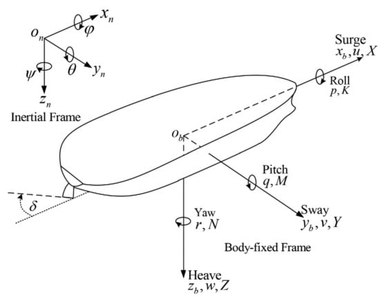
Figure 1.
Coordinate system for ship modeling.
Regarding the ship as a rigid body, the 6-DOF nonlinear equations of ship motion can be obtained by Newton’s law [29]. Since this paper mainly studies the use of fin stabilizer to reduce the heeling and rolling motion caused by ship turning and environmental disturbance, the pitch and heave attitudes, and their influence on the other four degrees of freedom can be neglected [30]. Therefore, the 4-DOF ship motion model in the surge, sway, roll and yaw can be obtained by Equation (1):
where m is the ship mass, xG and zG are the coordinates of the center of gravity (CG) in x and z axes, respectively, Ix and Iz are the moments of inertia about the x and z axes, u and v are the surge and sway velocity, respectively, p and r are the roll and yaw angular velocity, X and Y are the forces acting on the hull in x and y axes direction, respectively, K and N are the moments acting on the hull about x and z axes, respectively.
2.2. Hydrodynamic Forces and Moments
The hydrodynamic forces and moments can be expressed in the form of nonlinear functions of the ship’s position, velocity and acceleration, and are influenced by the shipping state and fluid characteristics [29]. In this paper, the nonlinear hydrodynamic expression is adopted as [1]:
where ρ is the fluid density, g is the gravity acceleration, ∇ is the ship displacement, φ is the roll angle, GZ(φ) is the righting arm curve, and the multipliers are the ship’s hydrodynamic coefficients.
2.3. Wave Disturbance Forces and Moments
Disturbances experienced by ships sailing at sea are mainly caused by sea winds, waves, and currents. Among them, sea waves are the main cause of ship rolling. Considering the research content of this paper, the disturbance forces and moments produced by sea waves are considered, and the wave forces and moments model is adopted as [31]:
where
where An, Bn, Cn, Dn, Gn and Hn are the corresponding coefficients of the first-order wave disturbance forces and moments. A(x), B(x), d(x) and zB(x) are the cross-section area of water immersion, beam, draft and the z coordinate of the center of the cross-section area of water immersion at the ship’s longitudinal coordinate of x, respectively. ωn and ωe are the wave frequency and encounter frequency, respectively. χ is the encounter angle. εn and Sζ(ωn) are the random phase and wave-height spectrum of the nth regular wave, respectively. NN is the number of regular waves.
2.4. Fin Forces and Moments
Fin stabilizers are installed in pairs on both sides of the bilge of the ship to have a large roll arm and anti-rolling moment. According to [1], the fin forces and moments can be approximated as:
where rf and FCG are the fin’s roll and yaw arms, respectively, βfin is the fin’s tilt angle, Tf and Nf are the fin-induced tangential and normal forces, respectively, and can be calculated by Equation (5):
where Lf and Df are the lift and drag forces generated on the fin, respectively, αf is the effective fin angle of attack.
2.5. Rudder Forces and Moments
The vast majority of ships rely on one or more vertical installed rudders to accomplish all the maneuvers [12]. Rudders are usually installed after the propeller below the stern line of the ship. According to [14], the rudder-induced forces and moments can be obtained, as shown in Equation (6)
where rr and LCG are the rudder’s roll and yaw arms, respectively, δ is the fin tilt angle, Lr and Dr are the lift and drag forces generated on the fin, respectively.
2.6. Propeller Forces and Moments
Most ships rely on propellers under the waterline of the stern to provide forward power. Under normal conditions, it can be considered that the propellers only produce a longitudinal force that drives the ship forward or backwards. When the ship sails straight at a constant speed, it can be considered that the effective thrust Te generated by the propeller is equal to the ship resistance XR. Perez suggested that the ship resistance can be considered to be approximately equal to X|u|uU2, where U is the ship sailing speed [1]. Martin pointed out through simulation that for ship turning at a fixed speed, the thrust generated by the propellers during the turning process can be approximately equal to the force before the turning and remains unchanged to simplify the study [12]. Therefore, according to [12], the forces and moments can be obtained, as shown in Equation (7):
where X|u|u is the hydrodynamic coefficient related to the surge velocity, and U0 is the initial speed before turning.
3. Ship Heel/Roll Control Using Fin
A multipurpose naval vessel with fin stabilizers and rudders is selected as the research object, the parameters of the vessel, fin and rudder are shown in Table 1 and Table 2, respectively. The fin angle that rolls the ship to port is defined as the positive fin angle. The rudder angle that turns the ship left is defined as the positive rudder angle. The seawater density is 1025 kg/m3. The hydrodynamic coefficients presented in Section 2.2 are shown in Table 3, where m is the mass of the ship and ∆ is the buoyancy of the ship.

Table 1.
Parameters of the vessel.

Table 2.
Parameters of the fin and rudder.

Table 3.
Hydrodynamic coefficients (from [1]).
The correctness and applicability of the established model have been verified in our previous work [10]. Figure 2 shows the simulation results of ship turning motion under different sea states. The simulation parameters are as follows: the initial ship speed is 15 m/s, the fin angle is 0°, the rudder angle is 30°, the rudder rate is 10°/s, the initial encounter angle is 90°.
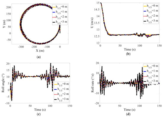
Figure 2.
Simulation results of ship turning motion under different sea states. (a) Trajectory; (b) ship speed; (c) roll angle; (d) roll rate.
It can be seen from Figure 2 that the turning trajectory of the ship under the interference of sea waves has a slight deviation compared to that in calm water, and the turning diameter is basically unchanged. The outward heel and ship speed in the steady turning phase also changed irregularly on the basis of the steady outward heel angle and the steady sailing speed of the turning in clam water, respectively. As the level of sea conditions increases, the changes in the state of motion, especially the turning heel, are also intensified. Under the interference of the waves with a significant wave height of 3 m, the turning outward heel angle reaches a maximum of 20°, which seriously affects the navigation safety and comfort of the ship. Therefore, the ship should try to avoid turning manoeuvres in higher sea conditions. The sea state level of the subsequent heel/roll reduction control simulations in this paper is limited to sea state 3 with a significant wave height of 1.25 m.
3.1. Ship Turning Motion with Fin Stabilizer
To investigate the effect of fin stabilizer on ship turning motion, the simulation of the ship turning in calm water with different fin angles of attack is conducted. The initial ship speed is 15 m/s, the rudder angle of attack is 30° and the rudder turning rate is 10°/s. The simulation results with fin angle of −20°, −10°, 0°, 10°, and 20° are shown in Figure 3. The main results data are given in Table 4. It should be noted that the total simulation time is 100 s, and the simulation results of the first 50 s of the roll angular velocity are given to clearly show the changes in the transition process.
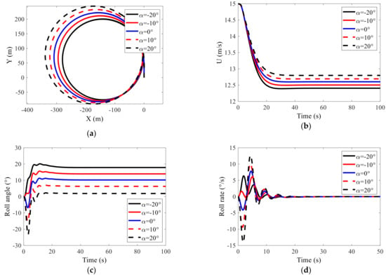
Figure 3.
Simulation results of ship turning motion under different fin angles. (a) Trajectory; (b) ship speed; (c) roll angle; (d) roll rate.

Table 4.
Simulation results of turning circle parameters under different fin angles.
It can be seen from Figure 3 and Table 4 that the positive and negative fin angles have opposite effects on the ship’s turning performance, and the strength of the influence increases as the fin angle increases. Under the action of a positive fin angle, the advance, turning radius and initial inward heel are increased compared to when the rudders act alone, while the maximum and steady outward heel angles are reduced. When the negative fin angle is acting, the opposite is true. In addition to the relatively small impact of the fin stabilizer on the speed reduction of turning, it also has a greater impact on other parameters such as the advance, turning diameter and turning heel. Therefore, the fin stabilizer can be used to assist the rudder to change the ship’s turning characteristics. In addition, it can be seen from the simulation results that the influence of the fin stabilizer on the steady turning diameter and steady outward heel is exactly the opposite. If one is reduced, the other is bound to increase. It is necessary to adjust the corresponding weight coefficients according to different control objectives to achieve relatively optimal control effects.
3.2. Fin Angle Speed Adjustment
It can be seen from the simulation results in Section 3.1 that fin stabilizers can be used to reduce the heel and roll motion during ship turns. It should be noted that to explore the law, the fin angle speed adjustment is not considered when setting the fin angle in the simulation of the front section. In the actual navigation of the ship, to protect the fin shaft from damage at high speeds, the speed adjustment problem must be considered when using fin stabilizers to reduce roll, which is, adjusting the maximum angle of attack of the fin according to the speed. In order to make the simulation results closer to the real situation, in this paper, the following fin angle speed adjustment law is adopted [32]:
where α*max is the real-time maximum fin angle, αmax is the maximum fin angle corresponding to the design speed, Udesign is the design speed. In this paper, Udesign and αmax are set to 18 kn and 25°, respectively.
4. Heel/Roll Reduction Control Using Fin Stabilizers
Based on the above discussion, the diagram of the heel/roll reduction control system using fin stabilizers during ship turns, as shown in Figure 4, can be obtained.
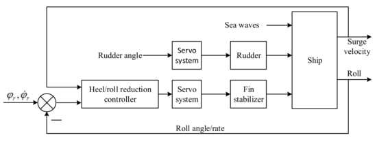
Figure 4.
Diagram of heel/roll reduction control using fin stabilizers during ship turns.
4.1. Control Model Analysis
As mentioned earlier, when using fin stabilizers to reduce the heel during the turning process, it will inevitably increase the turning diameter of the ship. Therefore, in order to simplify the analysis, only one degree of freedom of roll is considered. From the mathematical model of ship motion established in Section 2, the ship’s roll model is given by Equation (9):
Liang et al. pointed out that the sway acceleration term has little effect on the roll, and can be neglected [18]. In addition, when φ < 28°, sin(φ) can be approximately regarded as equal to φ. Therefore, ignoring the sway acceleration term and rewriting Kfin as Kfαf, Equation (9) can be rewritten as:
where Kf = ρAfu2CLrf, CL is the lift coefficient of the fin and Af is the fin area.
Define υ = αf, and Equation (10) can be further simplified as:
where
It can be seen that the equation describing the roll motion in the turning process is strongly nonlinear, and the parameters of the equation still have greater uncertainty due to the speed reduction of turning and the influence of external interference. In this paper, the L2-gain based adaptive robust control method is adopted to design the fin controller to reduce the turning heel and roll motion.
4.2. Controller Design
4.2.1. L2-Gain Adaptive Robust Control
For the disturbed uncertain nonlinear system described in Equation (12), suppose it satisfies the following assumptions in a certain neighborhood of the origin of the state space [33].
where x∈Rn, υ∈R, y∈R, and η∈R are the state vector, input, output and bounded disturbance of the system, respectively, γi(x) and β(x) are smooth vector fields with 0 ≤ i ≤ n, θ = (θ1,θ2,…,θp)T∈L2(0,∞) is the uncertain disturbance.
Hypothesis 1: (assumption of bounded interference) there is a constant d greater than zero, satisfying|η(x,t)| ≤ d;
Hypothesis 2: (achievable condition hypothesis) let
be the estimate of θ, for any ∈Bθ and x∈Bx, it needs to satisfy |β0(x) + βT(x)| > 0, where Bθ and Bx are the open balls that contain and x respectively in the parameter space. Compared with the control period, θ∈L2(0,∞) is usually regarded as a slowly changing quantity, so it can be approximately equal to zero.
Then, introduce the following theorem as [34].
Theorem 1.
For any positive real constant γ > 0, if the perturbed nonlinear system described in Equation (12), for any T ≥ 0 and θ∈L2(0,T), satisfy.
where N ≥ 0 is a finite constant, then the disturbing uncertain nonlinear system Equation (12) has L2-gain ≤ γ.
The design steps of L2-gain adaptive robust controller based on the backstepping method are briefly given below. For succinct description, let γi(x1, x2, …, xi) be γi, then when i = 1, we can get from Equation (12):
Assume x2* is the control input of the subsystem (14), and defined by Equation (15)
where c1 > 0 and k > 0 are undetermined coefficients.
Define the error term e2 = x2 − x2*, then
Define the Lyapunov function V1 as
Then we have Equation (18)
Substitute Equation (16) into (18), we can get Equation (19)
The last two terms on the right side of Equation (19) can be rewritten as
Let e1 = x1, then we have Equation (21)
For i = 2, define the Lyapunov function V2 as
Then we have Equation (23)
From the definition of the previous error term e2, we can get Equation (24)
Substitute Equation (24) into (23), we have
If α21 and α22 are
Then Equation (25) can be further written as
Let be the control input of the second subsystem, and define
Moreover, define the error term e3 between x3 and as
Substituting Equation (29) into (27), and performing a calculation similar to , we can get
Similarly, for 2 < i < n−1, define the Lyapunov function Vi as
If αi1, αi2 and the error term ei+1 between xi+1 and the control input of the ith subsystem are defined as
Similarly, we can get
For the nth subsystem, define the error term en as
Then we can have
Similarly, define αn1 and αn2 as
Then Equation (36) can be further written as
Define the Lyapunov function Vn as
Then we have
Define the adaptive control law as
Substituting the above adaptive control law into Equation (40), we can get
Equation can be further written as follows if we choose ci ≥ 1, 1 ≤ i ≤ n
Moreover, because y = x1 = e1, integrating both ends of Equation (44), we can get
where N > 0 is the initial value of Vn, γ2 = (n−1)/k.
It can be seen that, under the effect of the designed adaptive control law, the disturbed uncertain nonlinear system has L2-gain ≤ γ.
4.2.2. Design of Turning Heel/Roll Reduction Controller
For the disturbed and uncertain nonlinear turning heel/roll reduction system described in Equation (11), Let x1 = φ, x2 = p, then Equation (11) can be rewritten as:
Comparing the disturbed uncertain nonlinear system (46) and (12), it can be seen that the order of the turning hell/roll reduction system n is 2, and we can get
According to the design steps of the L2-gain adaptive robust law described in Section 4.2.1, we can get
The hyperbolic tangent function tanh(·) is used instead of the sign function sgn(·) to eliminate the chattering of the control signal caused by the hard handoff. The adaptive control law can be expressed as:
where c1 ≥ 1, c2 ≥ 1 and k > 0 are undetermined control parameters.
5. Result and Discussion
In this section, the simulation of the ship turning under wave disturbance are performed to verify the effectiveness of the designed L2-gain based adaptive robust controller. The simulation parameters are as follows: the significant wave height is 1.25 m, the initial encounter angle is 135°, the initial sailing speed is 15 m/s, the turning rudder angle is 30°. The other parameters can be found in Table 1 and Table 2. It can be seen from the simulation results in Section 3.1, the surge velocity during the turning process gradually decreases from the initial sailing speed of 15 m/s to about 12.6 m/s, and changes slightly on this basis. Considering the short duration of the steering phase and the transition phase during the turning process, the parameters of the steady-state turning is used to calculate the parameters of the disturbed and uncertain nonlinear turning heel/roll reduction system. Based on the above analysis, we can get b = 0.0146 and d = 0.2786. Design c1 = c2 = k = 4, then the adaptive control law can be obtained from Equations (52)–(54):
The simulation results of turning heel/roll reduction control using fin stabilizers based on the design L2-gain based adaptive robust controller are shown in Figure 5 and Figure 6. For comparison purposes, the simulation results a well-tuned PID controller are also given. NC, PID and L2ARC stand for “No control”, “PID control” and “L2-gain based adaptive robust control” respectively.
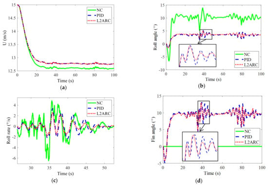
Figure 5.
Simulation results of L2-gain adaptive robust control under wave disturbance. (a) Ship speed; (b) roll angle; (c) roll rate; (d) fin angle.
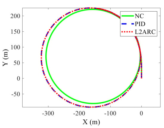
Figure 6.
Trajectory of L2-gain adaptive robust control under wave disturbance.
It can be seen from Figure 5 that both the designed L2-gain based adaptive robust controller (L2ARC) and a well-tuned PID controller can effectively reduce the heel and roll motion during ship turns. It can be seen from Figure 5a that the sailing speed of the ship under the action of the controller is slightly increased than that without control, from 12.6 m/s to 12.8 m/s. From Figure 5b,c, it can be seen that the roll and heel reduction control effect of the designed L2ARC is slightly better than a well-tuned PID controller, which shows the superiority of the proposed control strategy. The steady outward heel angle with L2ARC is reduced from 10.19° to 3.01°, and the heel reduction effect can be easily calculated to be about 70.5%. The mean square value of the roll angle during the steady turning phase is reduced from 1.26° to 0.52°, and the roll reduction effect can be easily calculated to be 58.7%. As the encounter angle changes continuously with the progress of the turning, so that the amplitude of the roll motion of the ship also changes periodically. The ship roll is more severe when the encounter angle is 90° or 270°, while other angles are gentler. The control effect of the two controllers is almost the same when the roll is small, but the control effect of L2ARC is better than that of the PID when the roll is large, which is more obvious in Figure 5c. It can be seen from Figure 5d that the fin angle under the action of L2ARC is significant smaller than that under the action of PID. The movement of the fins in the steady turning phase is reduced by approximately 10%, which means the reduction of energy consumption and the effectiveness of the designed L2ARC. The overall effect of the designed L2-gain based adaptive controller is slightly better than well-tuned PID control. In addition, due to the opposite effect of the fin stabilizer on the steady outward heel and turning diameter, the steady turning diameter increases by about 15 m compared with the situation without control, as shown in Figure 6. The simulation results show that the designed controller has good robustness against uncertainties caused by a speed reduction of turning and internal and external disturbance.
6. Conclusions
In this paper, the use of fin stabilizers to reduce the heel and roll during ship turns under wave disturbance is investigated. The 4-DOF nonlinear mathematical model of a multipurpose naval vessel with forces and moments caused by hydrodynamics, waves, fin stabilizers, rudders and propellers is established. Based on the analysis of ship turning motion with different fin angles in calm water, it is found that the fin stabilizer can be used to reduce the heel and roll motion during ship turns, and it has the opposite effect on the steady outward heel and steady turning diameter. Through the analysis, the model of the turning heel/roll reduction system, which is convenient for controller design is obtained. For this disturbed uncertain nonlinear system, the L2-gain based adaptive robust controller is adopted to realize the control of fin stabilizers to reduce the heel and roll during ship turns. Considering the influence of ship speed on the maximum fin angle, fin angle speed adjustment is added in the simulation to get close to the real situation. The simulation results show that both the design L2-based adaptive robust controller and the well-tuned PID controller can effectively reduce the heel and roll motion during ship turns, and the overall effect of the designed controller is slightly better than the well-tuned PID controller.
In the future, we will make further research on the current basis. If possible, we will conduct ship model and even real ship experiments to verify the effectiveness of our proposed method.
Author Contributions
Methodology, Z.S.; writing—original draft preparation, Z.S. and Z.P.; funding acquisition, Z.S. and Z.P.; writing—review and editing, Z.S. and Z.P. All authors have read and agreed to the published version of the manuscript.
Funding
This work is supported by the Doctorial Innovation Funds of Tangshan University under Grant 1402001, the Fundamental Research Funds for the Central Universities under grant HEUCFM170404 and Harbin Science and Technology Innovation Talent Research Special Fund under grant 2017RC2017XK009006.
Data Availability Statement
All the data are available in the article.
Conflicts of Interest
The authors declare no conflict of interest.
References
- Perez, T. Ship Motion Control: Course Keeping and Roll Stabilisation Using Rudder and Fins; Springer: London, UK, 2005. [Google Scholar]
- Jin, H.; Yao, X. Ship Control Principle, 2nd ed.; Harbin Engineering University: Harbin, China, 2013. [Google Scholar]
- Zhang, S.; Liang, L.; Sun, M.; Zhao, P. Fluid motion and stabilization effect prediction of anti-rolling tank coupled ship rolling. Chin. J. Comput. Mech. 2016, 33, 252–256. [Google Scholar]
- Lewis, E. Principles of Naval Architecture, 2nd ed.; SNAME: New Jersey, NJ, USA, 1989; Volume 3. [Google Scholar]
- Liang, L.; Zhao, P.; Zhang, S.; Yuan, J.; Wen, Y. Simulation and analysis of Magnus rotating roll stabilizer at low speed. Ocean Eng. 2017, 142, 491–500. [Google Scholar] [CrossRef]
- Perez, T.; Blanke, M. Ship roll damping control. Annu. Rev. Control 2012, 36, 129–147. [Google Scholar] [CrossRef]
- Fang, M.-C.; Luo, J.-H. On the track keeping and roll reduction of the ship in random waves using different sliding mode controllers. Ocean Eng. 2007, 34, 479–488. [Google Scholar] [CrossRef]
- Liu, Z.; Jin, H.; Grimble, M.J.; Katebi, R. Ship forward speed loss minimization using nonlinear course keeping and roll motion controllers. Ocean Eng. 2016, 113, 201–207. [Google Scholar] [CrossRef]
- Liang, L.; Wen, Y. Rudder roll stabilization with disturbance compensation model predictive control. J. Mar. Sci. Technol. 2019, 24, 249–259. [Google Scholar] [CrossRef]
- Zhao, P.; Liang, L.; Zhang, S.; Ji, M.; Yuan, J. Simulation analysis of rudder roll stabilization during ship turning motion. Ocean Eng. 2019, 189, 106322. [Google Scholar] [CrossRef]
- Jiguang, S.; Zhao, P.; Liang, L.; Ji, M. Force modeling of zero/low-velocity fin stabilizer and hydrofoil profile optimization. Ocean Eng. 2020, 213, 107635. [Google Scholar] [CrossRef]
- Martin, G. Fin Stabilizers as Maneuver Control Surfaces. Master’s Thesis, Naval Postgratude School, Monterey, CA, USA, 2003. [Google Scholar]
- Kummer, S.; Hardier, G.; Lambert, C. Heel Compensation for the Charles de Gaulle Aircraft Carrier: Principles and Control Structure. Presented at the RTO AVT Symposium on Fluid Dynamics Problems of Vehicles Operating near or in the Air-Sea Interface, Amsterdam, The Netherlands, 5–8 October 1998. [Google Scholar]
- Wang, D. Research on Effects of Ship Turning Performance under Rudder/Fin Control; Harbin Engineering University: Harbin, China, 2013. [Google Scholar]
- Zhang, S. Characteristics Research and Experimental Verification of Controlled Passive Tank; Harbin Engineering University: Harbin, China, 2013. [Google Scholar]
- Liang, L.; Liu, H.; Zhang, S. Research of rudder parameters optimization based on ship optimal turning diameter. Ship Eng. 2013, 35, 61–64. [Google Scholar]
- Liu, W. Research and Simulation of Ship Roll Control in Turning Motion; Harbin Engineering University: Harbin, China, 2017. [Google Scholar]
- Liang, L.; Zhao, P.; Zhang, S.; Ji, M. Simulation analysis of fin stabilizer on ship roll control during turning motion. Ocean Eng. 2018, 164, 733–748. [Google Scholar]
- Hinostroza, M.; Luo, W.; Soares, C. Robust fin control for ship roll stabilization based on L2-gain design. Ocean Eng. 2015, 94, 126–131. [Google Scholar] [CrossRef]
- Crossland, P. The effect of roll-stabilisation controllers on warship operational performance. Control. Eng. Pract. 2003, 11, 423–431. [Google Scholar] [CrossRef]
- Zhang, X. Robust Control for Nonlinear Systems and Its Application to the Lift Feedback Fin Stabilizer. Ph.D. Thesis, Harbin Engineering University, Harbin, China, 2002. [Google Scholar]
- Wang, X.; Zhang, X. Nonlinear robust control for rudder/fin joint system with nonlinear course keeping. Syst. Eng. Electron. 2008, 8, 1549–1552. [Google Scholar]
- Li, Z.; Yang, C.; Ding, N.; Bogdan, S.; Ge, T. Robust adaptive motion control for underwater remotely operated vehicles with velocity constraints. Int. J. Control Autom. Syst. 2012, 10, 421–429. [Google Scholar] [CrossRef]
- Kahveci, N.E.; Ioannou, P.A. Adaptive steering control for uncertain ship dynamics and stability analysis. Automatica 2013, 49, 685–697. [Google Scholar] [CrossRef]
- Zhang, G.; Zhang, X. Concise robust adaptive pah-following control of underactuated ships using DSC and MLP. IEEE J. Ocean. Eng. 2014, 39, 685–694. [Google Scholar] [CrossRef]
- Demirel, H.; Alarçin, F. Lmi—based H2 and H state—feedback controller design for fin stabilizer of nonlinear roll motion of a fishing boat. Brodogr. Teor. Praksa Brodogr. Pomor. Teh. 2016, 67, 91–107. [Google Scholar] [CrossRef][Green Version]
- Zwierzewice, Z. The design of ship autopilot via robust adaptive feedback linearization. In Proceedings of the 21st International Conference on Methods and Models in Automation and Robotics, Miedzyzdroje, Poland, 29 August–1 September 2016; pp. 665–670. [Google Scholar]
- Sun, Z.; Zhang, G.; Yi, B.; Zhang, W. Practical proportional integral sliding mode control for underactuated surface ships in the fields of marine practice. Ocean Eng. 2017, 142, 217–223. [Google Scholar] [CrossRef]
- Abkowitz, M. Lectures on Ship Hydrodynamics-Steering and Manoeuvrability; Technical Report; Hydro- and Aerodynamics Laboratory: Lyngby, Denmark, 1964. [Google Scholar]
- Söder, C.-J.; Rosén, A.; Ovegård, E.; Kuttenkeuler, J.; Huss, M. Parametric roll mitigation using rudder control. J. Mar. Sci. Technol. 2013, 18, 395–403. [Google Scholar] [CrossRef]
- Jia, L.; Yang, Y. Mathematical Model of Ship Motion; Dalian Maritime University Press: Dalian, China, 1999. [Google Scholar]
- Jin, H.; Wang, K.; Ji, M. Application of Intelligent Technique to Fin Stabilizers; National Defense Industry Press: Beijing, China, 2003. [Google Scholar]
- Chen, M.; Jiang, C.; Wu, Q.; Cao, B. Adaptive robust L2-gain control for a class of uncertain nonlinear systems. J. Nanjing Univ. Aeronaut. Astronaut. 2003, 35, 351–355. [Google Scholar]
- Yan, D.; He, Y.; Wu, Q. Adaptive robust control with L2-gain for a class of uncertain nonlinear systems. J. Chang’an Univ. (Nat. Sci. Ed.) 2006, 26, 102–105. [Google Scholar]
Publisher’s Note: MDPI stays neutral with regard to jurisdictional claims in published maps and institutional affiliations. |
© 2021 by the authors. Licensee MDPI, Basel, Switzerland. This article is an open access article distributed under the terms and conditions of the Creative Commons Attribution (CC BY) license (http://creativecommons.org/licenses/by/4.0/).