Article

Long-Term Durability of Marine Reinforced Concrete Structures

by
Robert E Melchers
Centre for Infrastructure Performance and Reliability, The University of Newcastle, Callaghan, NSW 2308, Australia
J. Mar. Sci. Eng. 2020, 8(4), 290; https://doi.org/10.3390/jmse8040290
Submission received: 9 March 2020 / Revised: 16 April 2020 / Accepted: 16 April 2020 / Published: 18 April 2020
(This article belongs to the Special Issue Sustainable Concrete in the Marine Environment)

Abstract

:
The sustainability of reinforced concrete is critical, particularly for structures exposed to marine environments. Chlorides are implicated in causing or accelerating reinforcement corrosion and potentially earlier expensive repairs, yet there are many older reinforced concrete structures in good condition for many decades despite very high chloride levels at the reinforcement. The reasons for this are reviewed briefly, together with recent experimental work that better defines the role of chlorides. One is initiation of reinforcement corrosion but only through localized pitting at air-voids in concrete at the interface with the steel reinforcement. These tend to be small or negligible for high quality well-compacted concretes. The other role for chlorides has been shown, in experimental work, to accelerate the long-term loss of concrete alkali material. On the other hand, a review of practical experience shows that what has been termed chloride-induced reinforcement corrosion often is not that at all, but is the end-product of factors that impair the protective nature of the concrete. As reviewed herein, these include poor compaction, physical damage to concrete cover, concrete shrinkage, and alkali-aggregate reactions. The various observations presented are important for the proper understanding, analysis, and design of durable reinforced concrete structures exposed to chloride-rich environments.

1. Introduction

Premature or early failure of reinforced concrete (RC) infrastructure located in marine environments potentially has significant economic, environmental, and sustainability implications and thus should be avoided, if possible. Despite decades of research, the precise mechanisms involved in the initiation and development of reinforced corrosion in marine environments and the subsequent possible structural damage remain elusive. This is unsatisfactory. It prevents sound design for long-term durability.
Under good conditions, concrete provides protection against reinforcement corrosion through providing physical shielding such as an adequate amount of concrete cover, or through the inhibiting effect of the usually high pH of the concrete surrounding the bars. There is now a considerable body of data from actual RC structures to demonstrate excellent resistance to reinforcement corrosion in a variety of marine and other environments, including in the immersion zone, the tidal zone, the splash zone, or in a marine, salt-laden atmosphere [1,2,3,4]. For some of these cases it was possible to perform very detailed investigations [3,5,6,7]. These demonstrated the very low or negligible degrees of reinforcement corrosion or corrosion damage, despite chloride concentrations much exceeding any conventionally accepted chloride threshold criterion [8,9]. In some cases, the investigations ascertained the remaining pH of the concrete and invariably this was shown to be high, indicating high reserves of concrete alkalinity and, therefore, protection effect. Clearly, if notice had been taken of the chloride threshold, some structures would have been condemned unnecessarily many years ago, with potentially high consequential and unnecessary costs.
The immediate question from the above is why there seems to be a mismatch between the current criteria (and therefore the current thinking) about reinforcement corrosion and actual field observations for high quality concrete structures, that is, those that are of high strength, low permeability, and high remaining alkalinity but that also have very high chloride concentrations. This question is reviewed below, using recent experimental observations, and some classical results that have been forgotten or ignored, but which are crucial to providing new insight into the mechanisms involved in chloride-related reinforcement corrosion. As will be seen, many of the conventionally desirable practical considerations remain valid, but the reasons for these can now be seen in a different light, reasons that are consistent with the long-term durability of well-made reinforced concrete structures.
One of the serious and perhaps puzzling observations that has been made recently is that in some RC structures, at locations where (hairline) cracking had penetrated all the way through to the reinforcement and after long exposure periods, highly localized and very serious corrosion loss has been observed [5,6]. While crack width is usually observed to be a critical parameter, these observations suggest that crack depth can be much more critical, as explained below. They also can be interpreted as examples of a wider potential problem, namely structural damage that permits, in certain cases, early corrosion initiation and potentially also progressive loss of alkalinity that then permits consequent corrosion aided by the presence of chlorides. Importantly, this observation leads to the concept that concretes and concrete cover to reinforcement impaired or damaged in some way are likely to lead to reinforcement corrosion issues. Similarly, there are likely to be reinforcement corrosion issues with poor quality, permeable concretes. As reviewed in the second part of the paper, many of these issues involved are known in isolation as potential problems for RC structures, but have not been considered in the context of creating conditions for subsequent chloride-related corrosion of reinforcement. Taken together with the new insights about pitting corrosion-induced initiation and eventual loss of concrete alkalis, these interpretations provide a more comprehensive view of what is conventionally thought of as ‘chloride-induced’ corrosion.

2. Marine Corrosion Conditions

2.1. Effect of Chlorides

Inside concrete the conditions can be characterized typically as (mostly) wet [10], with any pore-waters in an effectively stagnant state, possibly with chlorides present, possibly with air (oxygen, carbon dioxide) present, and initially well buffered in pH through the high alkalinity of concrete. Gaseous oxygen (O2) diffuses into good quality concretes less so than water and gaseous carbon dioxide (CO2) even less so. However, oxygen in the form of dissolved oxygen in water has greater accessibility. Corrosion of steel can occur under oxygenated conditions, consuming O2 and H2O (oxidation cathodic reaction) and also under certain anoxic conditions such as with imperfections and inclusions (e.g., MnS inclusions) [11], consuming only H2O and releasing gaseous H2 after disassociation of water (hydrogen evolution cathodic reaction) [12]. Typically, the first applies early in the corrosion process when there is some O2 available (as well as H2O), while the second occurs under anoxic conditions at the metal-corrosion product interface. However, external to the rusts, oxygen must be available [13,14] since oxygen is still the ultimate electron acceptor. If there is no oxygen as the ultimate electron acceptor under the conditions described above, corrosion will cease. Irrespective of which of these mechanisms applies, inside the concrete the conditions are stagnant.
Immersion corrosion of steels in stagnant conditions is almost uncorrelated with the type and the concentration of salts in the solution [15], including chloride solutions. The importance of the stagnant conditions was demonstrated by Mercer and Lumbard [16] who also found almost no effect on corrosion, irrespective of chloride concentration. They also showed that increasing the rotation of the specimen, i.e., the water velocity at the corrosion interface, increased corrosion. However, field tests show that this effect is lost as the rust layers build up [17].
These observations are important because many electrochemical tests for reinforcement corrosion have been conducted in test cells using stirred solutions (including artificial concrete pore waters, natural or artificial seawater, or salt water) or using rotating samples (electrodes). This is meant to speed up the reactions and to prevent the build up of corrosion products [18], but such test results are not relevant to corrosion inside actual concretes.
The use of stirred solutions [19] may explain in part the apparently rather odd result often quoted in the concrete corrosion literature [20] that corrosion in concretes commences when the pH of the pore water solution drops below about 11. To be sure, this may be true for pitting corrosion in chloride-rich solutions, but not for general corrosion, irrespective of chloride concentration [21]. This distinction is important, as discussed further below.

2.2. Corrosion Initiation

Initiation of reinforcement corrosion invariably has been related to a critical chloride content [9] and continues to be so considered in many publications, e.g., [22,23]. However, some recent experimental results have thrown a new light on these classical notions.
Model concrete specimens exposed for up to 12 years and examined by breaking one or two open (at approximately yearly intervals) have shown that even with seawater used as mixing water (and therefore with very high available chloride concentrations at the steel bar and elsewhere, even after allowing for bound chlorides [24]) there is an initial degree of corrosion but that this then stops or much reduces [25]. Similar observations have been made elsewhere [26,27] for a number of RC beams, close to full size rather than the laboratory samples used in the 12-year study. It also was found that for specimens of high strength (as assessed by rebound hammer) and thus of low permeability, corrosion did not progress very much with time. However, for the more permeable concretes corrosion was more severe, although in the experiments it was not enough to fracture the specimens even after 12 years. In essence, the observations showed corrosion behaviour shown in Figure 1 at around ti. It should be noted that the time period 0—ti was close to zero since these, as noted, the specimens were doped with chlorides from the beginning (i.e., with seawater).
Physical examination of the interior specimens by breaking them open showed, consistently, that corrosion was most prevalent on the lower side of the (6 mm diameter) steel bar. This was the side away from the (vertical) casting direction, with the specimens having been cast while in the horizontal direction. There was essentially no corrosion elsewhere (Figure 2a). Only for longer exposures inside permeable concretes was corrosion all around the bar observed.
Detailed microscope examination of multiple cross-sections of the specimens at right angles to the steel bar direction, after sectioning, showed localized corrosion of the steel bar with, directly opposite, but not necessarily aligned, voids in the concrete (Figure 2b). These voids in the concrete and the associated localized corrosion of the steel were always on the side of the steel bar closest to the shaking table, that is, under the bar when the concrete was cast. Observations of localized corrosion and voids under horizontal reinforcing bars have been made also for concrete beams in practice [28], providing direct consistency between these experimental results and practice. This contrasts with the usual assumption in most theoretical papers that corrosion occurs all around the bars, e.g., [29,30].
In brief, the corrosion mechanism involved [25] is pitting corrosion. Only this is thermodynamically possible under the effect of elevated chloride concentrations and elevated pH conditions [21]. This will produce the development of rusts (corrosion products) within and eventually outside the corrosion pits. As corrosion proceeds, oxygen will be consumed from within the voids. If the surrounding concrete is impervious corrosion will then stop owing to depletion of oxygen. In other cases, the longer-term corrosion will depend on the rate of inward diffusion of oxygen (and perhaps water) from elsewhere, usually the external environment. For high quality, low-permeable concretes this will be very slow, causing the very considerable decline in corrosion rate after time ti, shown with the bold trend in Figure 1. For poor quality, (higher permeability) concretes the subsequent rate of corrosion will be higher, as also shown in Figure 1.
In concretes poorly compacted around the reinforcing bars, large voids are likely to occur at the concrete-steel interface. This will permit the production of much rust owing to the higher availability of oxygen in the larger voids. The build up of rusts may fracture the concrete cover, causing cracking and subsequently greater access of oxygen (and water). In turn, this may lead to significant corrosion damage. As noted, many researchers [e.g., 29,30] have assumed that corrosion occurs all around the bars—however, Figure 2 shows that corrosion is much more localized, at the bottom of horizontally oriented bars, consistent with observations in practice [28]. Corrosion all around bars would be possible only for very permeable concretes and vertically oriented bars. The implications of the preferential location of the corrosion, the consequential build up of corrosion products, and the effect on concrete cracking and spalling or delamination of the cover does not yet appear to have received research attention.
One piece of evidence to support the above can be seen in Figure 3. It shows the cross-section of a thick concrete slab used at one time for a harbour deck facility and exposed since the 1930s to marine (atmospheric) conditions. Importantly, it showed no evidence of over-stress due to bending, such as transverse cracking along the base of the slab. Some of the rust staining seen is the result of the slab segment having been left in the weather for a few weeks prior to examination. The important observation is the crack running along the top edge of the slab. It passes through the bottoms of all the bars, directly leading to cover delamination.

2.3. Corrosion in Concretes of Low Permeability

The commencement of corrosion after tact (Figure 1) involves a completely different mechanism to that earlier. This was uncovered recently using laboratory specimens similar to those mentioned above [25,31,32]. The interpretation was that for longer term exposures the principal concrete alkaline material Ca(OH)2 had undergone gradual dissolution, that this was aided by the presence of chlorides [33], and subsequently that it had leached out of the concrete matrix. The loss of this material effectively opened the concrete matrix and this allowed oxygen to enter into the concrete, and when sufficient leaching had occurred, including to the reinforcement. The loss of local alkalinity then allowed reinforcement corrosion. The interpretation that should be placed on these observations is that the more permeable concretes have greater internal surface areas exposed for alkali dissolution, rather than that they directly permitted greater diffusion of species through the more permeable concrete. The rate-limiting step is alkali dissolution, not alkali diffusion (and thus permeability). It should be clear that for high quality, low permeability concretes the eventual loss of concrete alkalinity is unlikely to be reached within the normal lifespan of many practical structures, as exemplified for some actual reinforced concrete structures [5,6,7].

3. Initiating Mechanisms for Reinforcement Corrosion

The initiation of reinforcement corrosion was associated with the presence of voids in the concrete at its interface with the steel reinforcement. These provide the local sources of water and oxygen necessary for corrosion to be possible. It also is necessary, in high pH environments such as in concretes, to have a sufficiently high concentration of chloride ions, thereby permitting localized pitting corrosion [21].
If there are no voids in the concrete at the concrete-steel interface there would be negligible oxygen available to support the initiation of the corrosion process. This is consistent with the laboratory observations for the extremely well-compacted concretes that showed no voids [25]. It also is consistent with field observations [6] and with the claim that the presence of voids is a necessary condition for corrosion initiation [34], based on electrochemical experiments that produced very small voids as a result of localized dissolution of Ca(OH)2 at the concrete-steel interface. This immediately raises the question that if the voids, with their oxygen and water, are not present, what then could cause corrosion initiation?
In a provocative article based on extensive practical experience and observations, and interpreting field observations by others, Borgard et al. [35] proposed that in many cases the initiation and subsequent development of reinforcement was a consequence of cracking, shrinkage, and other damage of the concrete cover. Such damage would expose part or all of the reinforcement steel and with oxygen and water then available would allow corrosion to occur, irrespective of the presence or otherwise of chlorides. These practical observations appear mostly to have been ignored or forgotten. They almost completely invert the idea of ‘chloride-induced’ corrosion. They also mean that to fully understand practical observations of corrosion in chloride-rich environments, it is necessary to understand the potential mechanisms that may be involved. These are now briefly reviewed.

3.1. Physical Damage to the Concrete cover

Corrosion and consequent failure of RC bridge decks in areas where calcium chloride or other de-icing salts are applied has caused much concern for reinforcement corrosion, particularly in the US [36]. However, already in the 1970s Stratfull and van Matre [37] showed there was little correlation between the concentration of chlorides and corrosion damage of concrete bridge decks. Subsequent investigations showed that corrosion was related directly to failure of the concrete cover at the very top of the bridge decks and this was the case for many US bridges [38]. This type of damage permits direct access of moisture (and also chlorides from the de-icing salts) with subsequent corrosion and corrosion damage. Moreover, since chlorides are hygroscopic, they tend to retain moisture, thereby increasing what in atmospheric corrosion is termed the ‘time of wetness’, a key factor in atmospheric corrosion severity [8,12].
In Europe, the effect of de-icing salts appears to have been a lesser issue [39]. This may be because of different (lower) rates of application of de-icing salts. However, an important aspect appears to be differences in the quality of the riding surfaces. Those in Europe tend to be better overall, with particularly the older US reinforced concrete bridges often lacking a bitumen wearing or riding course that reduces impact but also provides a degree of moisture protection. A detailed German study [40] showed that reinforcement corrosion was often attributable to damage of the concrete cover caused by vehicle loading and impact, particularly from heavy goods vehicles. It concluded that reinforcement corrosion was a consequence of prior damage to the concrete cover. It found no evidence of corrosion initiated solely by chlorides in good quality concrete.

3.2. Concrete Shrinkage

Particularly for RC bridge decks, shrinkage of the concrete may cause cracking of the deck, and if severe may extend down to the reinforcement and possibly further [41]. The severity of shrinkage has been related to the increased use of high-performance concretes since these produce greater shrinkage and have less capacity for slow creep. Plasticizers for workability and aerating additives to control freeze-thaw activity also have been implicated [38]. Concrete cracking has been considered by some highly experienced practitioners and forensic investigators to be by far the most serious problem for concrete bridge deck deterioration and for subsequent reinforcement corrosion, irrespective of whether chloride environments were involved or not [42].

3.3. Deep Cracking

Cracking of concrete slabs and beams usually is associated with cracking parallel to the alignment of the reinforcement, caused by the build up of rusts. For these, the crack width usually is proscribed to a maximum width, typically 0.3 mm, a value based on early work in the UK, using shorter-term laboratory tests [43]. In view of practical experience showing that sometimes cracks self-heal and others appear not to cause reinforcement corrosion in medium-term exposures, the validity of this criterion has been questioned [42]. This suggests it is likely that such cracking somewhat facilitates very localized chloride, oxygen, and moisture diffusion but whether this has the effect of initiating corrosion, or support its continuation, depends very much on the local alkalinity conditions.
Longitudinal cracking is not the only type of cracking that occurs in reinforced concrete structures. Transverse cracks resulting from flexural action can cause serious reinforcement corrosion particularly in a marine condition if the cracks are deep enough to intersect with the reinforcing bars [5,6]. Figure 4 shows an example. Similar cases can be seen in other reports [5,6]. A preliminary analysis suggests that such corrosion is likely caused by the development of low pH, highly soluble ferrous chlorides inside the oxygen-poor conditions well inside the deep cracks. However, it is ultimately a consequential effect arising from the prior deep cracking—and this is not ‘chloride induced’.

3.4. Compaction

Compaction of the concrete as a critical requirement for durability of reinforced concrete structures has long been recognized. Conventionally, it is considered highly desirable to reduce permeability and thus the rate of inward diffusion of chlorides from the environment to the reinforcement bars [8]. The relevance of chloride migration has been questioned for many years [4]. Moreover, there are now a number of known, well-documented cases of very high chloride concentrations at the steel reinforcement without occurrence of corrosion [5,6,7]. More recent research has provided a more complete picture of the conditions for reinforcement corrosion initiation and its eventual progression. As noted above, it has shown that a sufficiently high concentration of chlorides is required to initiate corrosion, but only as pitting corrosion at air-voids immediately adjacent to the steel bars [25]. The role of concrete permeability lies mainly in retarding the long-term dissolution and loss of concrete alkalis [32]. As shown in Figure 1, there is also a role for concrete compaction in controlling the rate of ingress of oxygen, most likely mainly as dissolved oxygen in water, for the period after ti when on-going corrosion still progresses within a homogeneous concrete matrix, until at some time, such as tact, the expansion of rusts is sufficient to cause serious damage and subsequent corrosion occurs at a much higher rate owing to the loss of effective cover.
Compaction also can affect the presence of voids, as shown in Figure 2, and the quality (i.e., the degree of impermeability) of the concrete cover on the lower sides of bottom bars. It is well-recognized in practice that such cover (and also that in narrow forms) can be impaired by a poor choice of maximum aggregate size in relation to the thickness of the cover and also by the quality of compaction. However, the logic presented for this always has been in terms of chloride migration to the steel bars [8]. It should now be clear that it actually relates to the degree of access of oxygen, and perhaps water, to the bars. This is marked schematically in Figure 1 between ti and tact.
In the early days of reinforced concrete construction, compaction of the concrete was achieved using (vertical action) hand-rodding of the still wet mix with a small diameter steel or timber bars or rods, perhaps also with hand-tamping of the surface. This laborious process was replaced during the 1940s when mechanical means to vibrate the concrete formwork became available [44]. Poker or rod vibrators became available later. It has always been assumed that these systems were effective in achieving good compaction. Usually, this was judged by the appearance of air bubbles at the concrete surface, at which point compaction was judged sufficiently, or by visual observation of the size of voids revealed on concrete surfaces on stripping the formwork. However, recent preliminary investigations of the size of air-voids left immediately adjacent to reinforcing bars have shown that, despite considerable scatter between repeat results, typically form-vibration produced smaller voids below horizontal bars than did hand tamping or poker vibration, and that these methods were both less efficient for deformed bars and for prestressing cables. There was some effect related to the amount of physical effort that was applied. The size of air-voids appeared to depend on concrete mix workability, with stiffer mixes producing greater air-voids, as might be expected. Therefore, it is of interest that concretes made in the 1930s and 1940s, when adding water over the theoretical water-cement ratio was permitted for achieving good workability [45], tend to reveal concretes with rather few and only small air-voids. Such concretes tend to show only nominal or no corrosion [5,6]. However, the preliminary test results also showed that very wet mixes tend to produce somewhat bigger voids, likely the result of greater concrete shrinkage. The effect of compaction on air-voids at the concrete-steel interface, and the effect this has in corrosion, appears to have had little or no research attention. However, in view of the discontinuous behaviour shown in Figure 1 at ta, it can now be considered to be of some importance.

3.5. Alkali-Aggregate Reactions

One damage mechanism that also has received only limited attention in regard to reinforcement corrosion is deterioration of the protective capacity of concrete cover as a result of alkali-reactivity that affects some aggregates. Typically, the aggregates expand and become softer, weaker, and thus more permeable. For some aggregates this effect becomes noticeable within a few years of first exposure but in others it may take several decades [46].
That alkali-aggregate reaction (AAR) can have a significant influence on subsequent reinforcement corrosion as evident in a review [1] of an earlier summary of some 300 cases of RC structures reported in the literature, that had been cross-linked with data for types of aggregate used and with likely chloride concentrations [47]. It noted that both ti and tact (Figure 1) were subject to considerable scatter irrespective of chloride concentration. The re-appraisal of the data sources indicated that much of this scatter was related to concrete made in regions or locations where there was a record of AAR. One example is the RC housing near the Yucatan (MX) coastline that shows large areas of loss of concrete cover but mostly only superficial reinforcement corrosion [48], most likely having occurred after loss of cover occurred. Another is the damage caused by AAR to the concrete cover for the Barra bridge in Porto (P) [49]. A further example relates to many RC structures built in Norway where sensitivity to AAR appears to be high [50].
Although the possibility of AAR affecting concretes was long denied in the UK (and many other countries [46,51]), subsequent analyses of some 200 bridges in the UK [52] showed that up to 50% had some signs, or worse, of the effects of AAR, although in only a few cases was there significant structural damage. Elsewhere, it has been noted that for RC structures with a relatively thin concrete cover to the reinforcing bars the crack patterns caused by AAR (and the effect of surface shrinkage) can emulate the type of cracking along the lines of the reinforcement, as usually associated with chloride-induced corrosion [53]. However, almost certainly in these cases any reinforcement corrosion in the local chloride-rich environments was consequential on the prior failure of the concrete cover. These cases, therefore, should not be attributed to chloride-induced corrosion.

4. Discussion

It is clear from the above reviews and the interpretations from recent research that concrete permeability plays a major role, not so much in preventing the ingress of chlorides, a topic that appears to dominate all discussions about durability in marine environments, but rather for access of oxygen for corrosion subsequent to ti (Figure 1) in the case of the more permeable concretes, and in the case of highly impermeable concretes, for the rate of alkali dissolution that then, eventually, allows corrosion to proceed. However, as shown by practical examples, the latter process can take decades to occur. In both cases, chloride adds a dimension to the basic deterioration mechanisms but is not the prime driver of reinforcement corrosion as assumed in conventional thinking.
The central role of oxygen appears often overlooked, even in marine environments. Yet, its importance is easily demonstrated. Steel piles driven into marine sands typically show essentially no corrosion, even after many decades of exposure (except at the sand-water interface), despite the high chloride presence. This favourable behaviour is attributed entirely to the inability of oxygen to reach the soil-steel interface [54]. A similar scenario occurs for cast iron pipes (largely ferrous iron) densely packed with clays or other soils not showing any corrosion even after long periods of exposure [55]. This can be rationalized as showing that the interface between iron, soil, and water is essentially deprived of oxygen. When some oxygen can reach the corroding metal the role of water becomes very clear [56] and there is an effect similar to that at ti in Figure 1. In neither of these cases are alkalis involved. The implication is that even for concretes, which already have extra protection from alkalis, keeping oxygen out is an important criterion. Of course, without water corrosion would not occur—but in practice this may be somewhat more difficult to achieve.
It follows from the above that a sound aim for avoiding reinforcement corrosion in marine environments is to keep chlorides away—this will reduce the possibility of corrosion initiation at voids at the interface and eventually possibly causing cracking of the concrete along reinforcement bars. Lack of chlorides also will reduce the rate of loss of calcium hydroxide from the concrete matrix. Further, at deep cracks, lack of chlorides will not permit formation of the aggressive localized corrosion and the formation of the soluble rust ferrous chloride. When chlorides are inevitable as typical in marine environments, the next best strategy is to achieve a highly impermeable concrete with a high degree of alkalinity. The latter will be helpful in reducing the rate of chloride inward migration and so extending the time 0—ti, in reducing the likelihood of corrosion initiation and in reducing the rate of alkali dissolution, and so increasing the time tact. A high alkalinity and impermeability also may reduce the proneness to very localized attack at deep, fine cracks, but this remains a matter for further investigation.
Reduction in the size of air-voids also is likely to be beneficial. Their size governs the amount of corrosion products generated and, therefore, the propensity to cracking and spalling as these products build up in the period after ti. The important observation is that the corrosion products form predominantly on the lower parts of (horizontal) reinforcing bars and, therefore, are particularly influential in cracking and spalling along the lower surfaces of beams and slabs and for cracking and spalling at the sides of beams. Relatively, for the same nominal cover, the tops of slabs are likely to show cracking and spalling later since the actual distance between the built-up corrosion product and the outside surface is the nominal cover plus the bar diameter (Figure 3) (and, of course, the top surface may be less wet overall). In practice, however, compaction is likely to be less at the top and this may foster earlier reinforcement corrosion. Again, these issues are primarily related to workmanship and quality of construction. They are not the direct result of the presence of chlorides.
The notion that some progression of reinforcement corrosion might be permitted for practical structures, as implied in the central part of Figure 1, after ti, is likely to be a second-best option, perhaps to be contemplated only when low permeability of concrete cannot be achieved and air-voids are large—in other words when the concrete quality is relatively poor. Producing such concretes should not be considered acceptable and flies in the face of much practical advice over many decades [42] that has been echoed many times: ‘dense, impervious, relatively non-absorbent concrete’, adequate concrete cover, sufficiently high cement content, a low water/cement ratio, nonreactive aggregates, and good compaction and curing [57].
Finally, not everything conventionally attributed to chloride-induced corrosion is primarily due to chloride effects. As noted, many cases are due to failure of the concrete cover, resulting from AARs or mechanical damage, and only after this has occurred does corrosion of the steel occur. Additionally, surprising as it may seem, corrosion is not always worse in seawater compared to, say, rainwater or other soft, fresh water [58].

5. Conclusions

(1)
The interpretations presented show that the primary influences of chlorides are in (1) permitting localized (pitting) corrosion to occur at wet air-voids in concrete despite their high concrete alkalinity and thus pH, and (2) accelerating the dissolution of calcium hydroxide from the concrete, by gradually reducing the concrete pH sufficient for general corrosion to be possible under the normal thermodynamic conditions.
(2)
Sufficient evidence now exists that reinforced concrete structures in marine environments can survive a long time without reinforcement corrosion, despite high concentrations of chlorides in the concrete. This requires concretes of low permeability that are well compacted around the reinforcement bars so as to leave minimal air-voids.
(3)
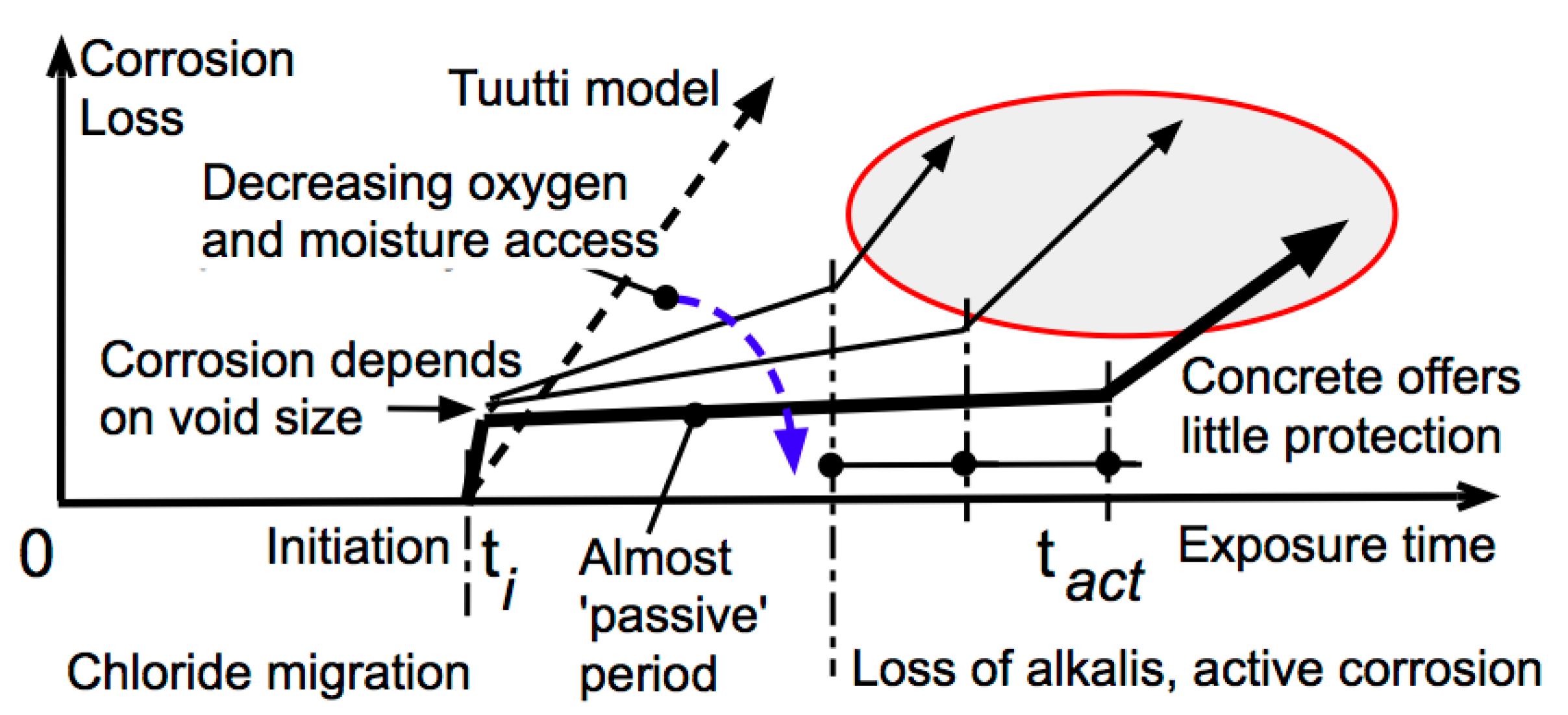
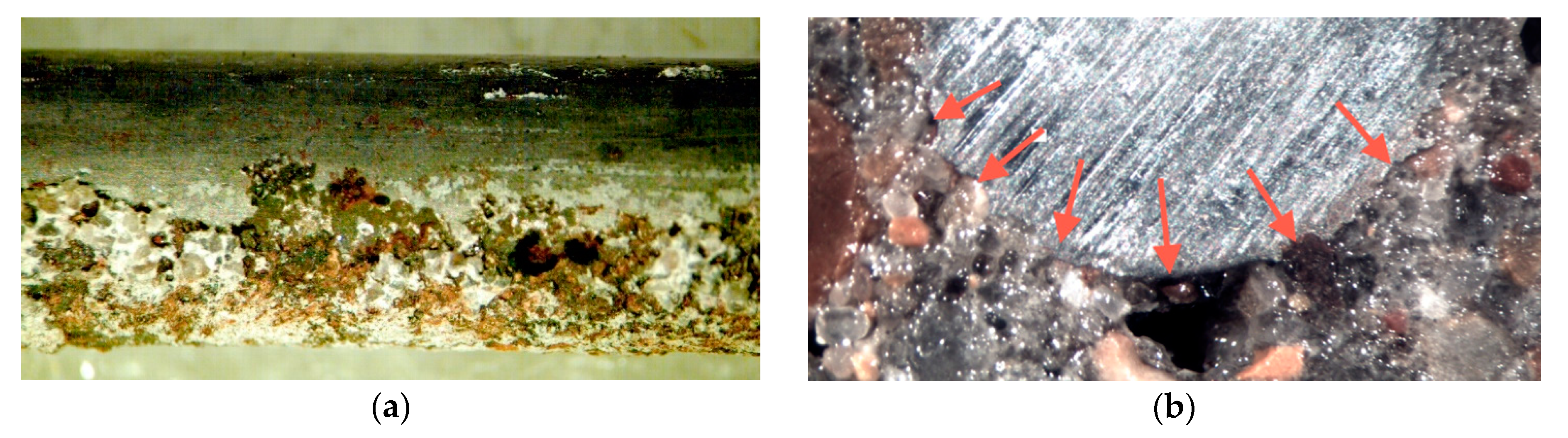
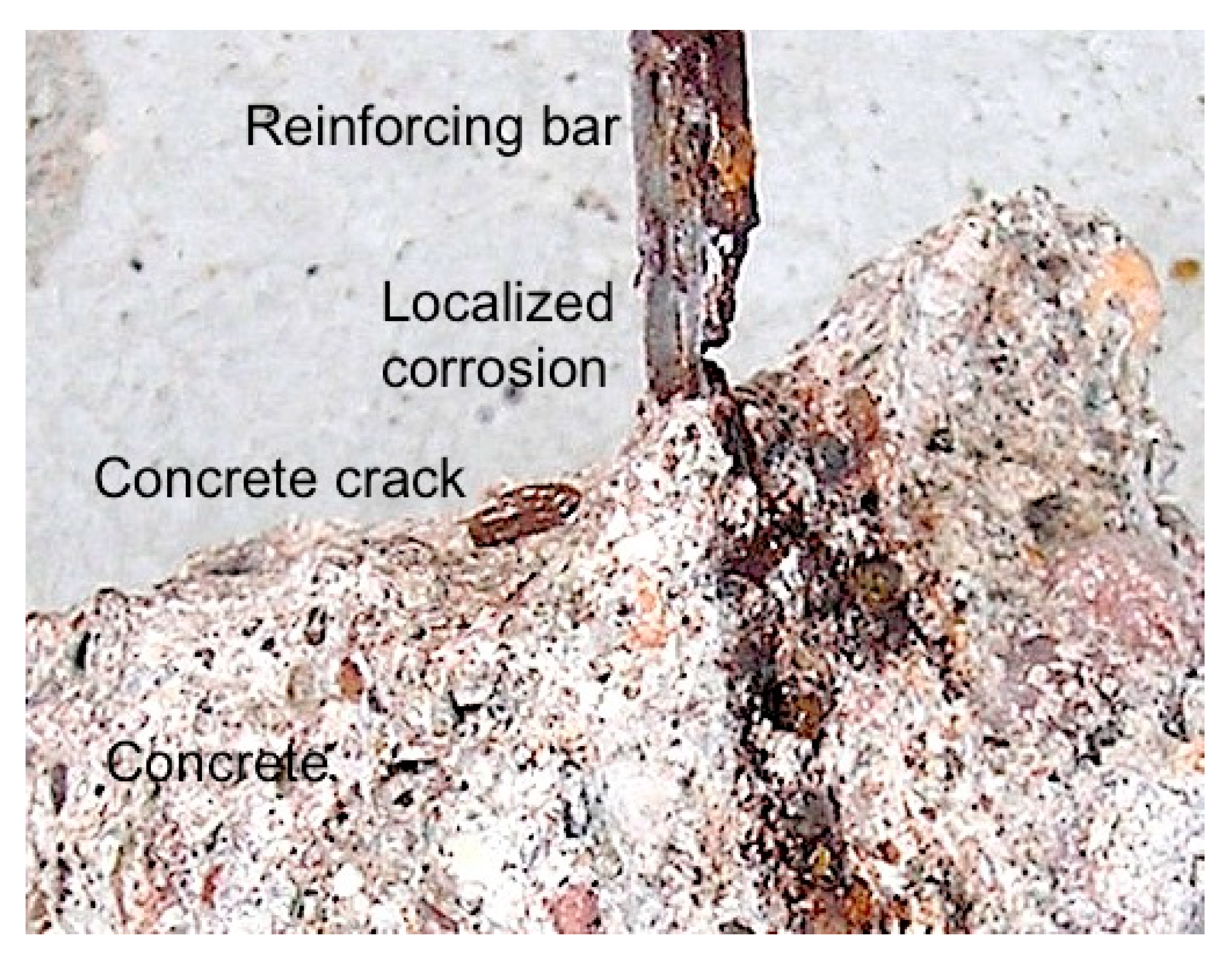
Concretes that are not well compacted around the steel bars and that are more permeable will permit localized corrosion to commence by differential aeration at the wet, chloride-rich, air-voids even when the concrete is still highly alkaline. Corrosion can then continue to occur, initially at the voids, but eventually more generally as the concrete cracks, with the overall rate limited by the rate of supply of oxygen. In a given environment, this, in turn, is a function of the permeability and thickness of the concrete cover.
(4)
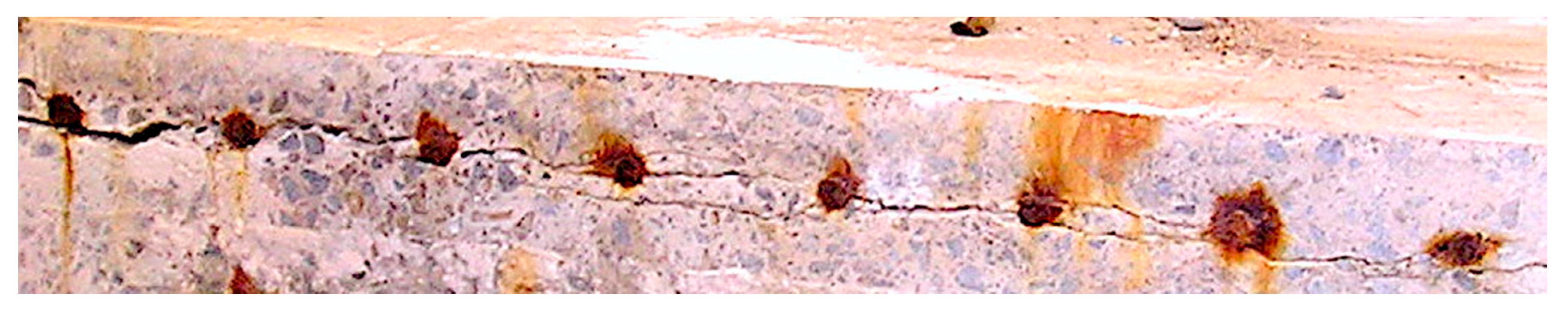
In practice, the air-voids occur primarily along the lower parts of horizontal reinforcing bars in vertically cast, concrete members. When corrosion occurs, the concretes may delaminate there, with the fracture line typically passing through the original air-void spaces.
(5)
Although the essential classical criteria for achieving a long durability of steel reinforced concrete structures have not changed, the recent research results threw new light on the reasons involved. They also indicate rational approaches to achieve long-term durability.

Funding

This research received no external funding.

Conflicts of Interest

The author declares no conflict of interest.

References

  1. Melchers, R.E. Observations about the time to commencement of reinforcement corrosion for concrete structures in marine environments. In Proceedings of the Consec’10, Concrete Under Severe Conditions, Yucatan, Mexico, 7–9 June 2010; Castro-Borges, P., Moreno, E.I., Sakai, K., Gjorv, O.E., Banthia, N., Eds.; CRC Press: Boca Raton, FL, USA, 2010; pp. 617–624. [Google Scholar]
  2. Melchers, R.E. Observations about the corrosion of reinforcement in marine environments. In Proceedings of the XII DBMC International Conference on Durability of Building Materials and Components, Porto, Portugal, 12–15 April 2011. paper 6.59. [Google Scholar]
  3. Angst, U.M.; Elsener, B.; Jamali, A.; Adey, B. Concrete cover cracking owing to reinforcement corrosion —Theoretical considerations and practical experience. Mater. Corros. 2012, 63, 1069–1077. [Google Scholar] [CrossRef]
  4. Melchers, R.E.; Chaves, I.A. A comparative study of chlorides and longer-term reinforcement corrosion. Mater. Corros. 2017, 68, 613–621. [Google Scholar] [CrossRef]
  5. Melchers, R.E.; Li, C.Q.; Davison, M.A. Observations and analysis of a 63-year old reinforced concrete promenade railing exposed to the North Sea. Mag. Concr. Res. 2009, 61, 233–243. [Google Scholar] [CrossRef] [Green Version]
  6. Melchers, R.E.; Pape, T.M.; Chaves, I.A.; Heywood, R. Long-term durability of reinforced concrete piles from the Hornibrook Highway bridge. Aust. J. Struct. Eng. 2017, 18, 41–57. [Google Scholar] [CrossRef]
  7. Melchers, R.E.; Howlett, C.H. Reinforcement corrosion of the Phoenix caissons after 75 years of marine exposure. Proc. ICE Marit. Eng. 2019. submitted for publication. [Google Scholar]
  8. Richardson, M.G. Fundamentals of Durable Reinforced Concrete; Spon Press: London, UK, 2002. [Google Scholar]
  9. Angst, U.M.; Elsener, B.; Larsen, C.K.; Vennesland, O. Critical chloride content in reinforced concrete—A review. Cem. Concr. Res. 2009, 39, 1122–1138. [Google Scholar] [CrossRef]
  10. Hadley, H.M. Concrete in seawater: A revised viewpoint needed. Proc. ASCE 1941, 107, 345–358, Discussion 359–394. [Google Scholar]
  11. Wranglen, G. Pitting and sulphide inclusions in steel. Corros. Sci. 1974, 14, 331–349. [Google Scholar] [CrossRef]
  12. Jones, D.A. Principles and Prevention of Corrosion, 2nd ed.; Prentice-Hall: Upper Saddle River, NJ, USA, 1996. [Google Scholar]
  13. Evans, U.R.; Taylor, C.A.J. Mechanics of atmospheric rusting. Corros. Sci. 1972, 2, 227–246. [Google Scholar] [CrossRef]
  14. Stratmann, M.; Bohnenkamp, K.; Engell, H.J. An electrochemical study of phase-transitions in rust layers. Corros. Sci. 1983, 23, 969–985. [Google Scholar] [CrossRef]
  15. Heyn, E.; Bauer, O. Ueber den Angriff des Eisens durch Wasser und wässerige Losungen. Stahl Eisen 1908, 28, 1564–1573. [Google Scholar]
  16. Mercer, A.D.; Lumbard, E.A. Corrosion of mild steel in water. Br. Corr. J. 1995, 30, 43–55. [Google Scholar] [CrossRef]
  17. Melchers, R.E.; Jeffrey, R. Influence of water velocity on marine corrosion of mild steel. Corrosion 2004, 60, 84–94. [Google Scholar] [CrossRef]
  18. Kelly, R.G.; Scully, J.R.; Shoesmith, D.; Buchheit, R.G. Electrochemical Techniques in Corrosion Science and Engineering; CRC Press: Dekker, NY, USA, 2003. [Google Scholar]
  19. Escalante, E.; Ito, S. Measuring the rate of corrosion of steel in concrete. In Corrosion Rates of Steel in Concrete; Berke, N.S., Chaker, V., Whiting, D., Eds.; ASTM STP 1065; American Society for Testing and Materials: Philadelphia, PA, USA, 1990; pp. 86–102. [Google Scholar]
  20. Gjorv, O.E. Durability Design of Concrete Structures in Severe Environments; Taylor & Francis: London, UK, 2009. [Google Scholar]
  21. Pourbaix, M. Significance of protection potential in pitting and intergranular corrosion. Corrosion 1970, 26, 431–438. [Google Scholar] [CrossRef]
  22. Delby, F.; Carcasses, M.; Sellier, A. Probabilistic approach for durability design of reinforced concrete in marine environment. Cem. Concr. Res. 2009, 39, 466–471. [Google Scholar]
  23. Alonso, C.; Castellote, M.; Andrade, C. Chloride threshold dependence of pitting potential of reinforcements. Electrochim. Acta 2002, 47, 3469–3481. [Google Scholar] [CrossRef]
  24. Glass, G.K.; Buenfeld, N.R. The presentation of the chloride threshold level for corrosion of steel in concrete. Corros. Sci. 1997, 39, 1001–1013. [Google Scholar] [CrossRef]
  25. Melchers, R.E.; Chaves, I.A. Reinforcement corrosion in marine concretes—1 initiation. ACI Mater. J. 2019, 116, 57–66. [Google Scholar] [CrossRef]
  26. Francois, R.; Arliguie, G. Effect of microcracking and cracking on the development of corrosion in reinforced concrete members. Mag. Conc. Res. 1999, 51, 143–150. [Google Scholar] [CrossRef]
  27. Linwen, Y.; Francois, R.; Hiep Dang, V.; Gagne, R. Development of chloride-induced corrosion in pre-cracked RC beams under sustained loading: Effect of load-induced cracks, concrete cover, and exposure conditions. Cem. Concr. Res. 2015, 67, 246–258. [Google Scholar]
  28. Nawy, E.G. Concrete Construction Engineering Handbook; CRC Press: Boca Raton, FL, USA, 2008; pp. 30–57. [Google Scholar]
  29. Du, X.; Zhang, R. Modeling the cracking of cover concrete due to non-uniform corrosion of reinforcement. Corros. Sci. 2014, 89, 189–202. [Google Scholar] [CrossRef]
  30. Li, C.Q.; Zheng, J.J.; Lawanwisut, W.; Melchers, R.E. Concrete delamination caused by steel reinforcement corrosion. J. Mater. Civil. Eng. 2007, 19, 591–600. [Google Scholar] [CrossRef]
  31. Melchers, R.E.; Chaves, I.A. A study of initiation and active reinforcement corrosion in conventional reinforced concrete. In Proceedings of the Corrosion and Prevention 2016, Auckland, New Zealand, 13–16 November 2016; 2016. Paper 052. [Google Scholar]
  32. Melchers, R.E.; Chaves, I.A. Reinforcement corrosion in marine concretes—2. long term corrosion. ACI Mater. J. 2020. proofs accepted. [Google Scholar] [CrossRef]
  33. Johnston, J.; Grove, C. The solubility of calcium hydroxide in aqueous salt solutions. J. Am. Chem. Soc. 1931, 53, 3976–3991. [Google Scholar] [CrossRef]
  34. Yonezawa, T.; Ashworth, V.; Proctor, R.P.M. Pore composition and chloride effects on the corrosion of steel in concrete. Corrosion 1988, 44, 489–499. [Google Scholar] [CrossRef]
  35. Borgard, B.; Warren, C.; Somayaji, S.; Heidersbach, R. Mechanism of corrosion of steel in concrete. In Corrosion Rates of Steel in Concrete; Berke, N.S., Chater, V., Whiting, D., Eds.; ASTM STP 1065; American Society for Testing and Materials: Philadelphia, PA, USA, 1990; pp. 174–188. [Google Scholar]
  36. Burkowsky, B.; Englot, J. Analyzing good deck performance on Port Authority bridges. Concr. Int. 1988, 10, 25–33. [Google Scholar]
  37. Stratfull, R.F.; van Matre, V. Corrosion Autopsy of a Structurally Unsound Bridge Deck; Report No. M/R-635116-8, PB-218843/1; California State Division of Highways; Material and Research Department: Washington, DC, USA, 1972. [Google Scholar]
  38. Krauss, P.D.; Rogalla, E.A. Transverse Cracking in Newly Constructed Bridge Decks; NCHRP Report No. 380; Transportation Research Record: Washington, DC, USA, 1966; p. 126. [Google Scholar]
  39. Lukas, W. Relationship between chloride content in concrete and corrosion in untensioned reinforcement on Austrian bridges and concrete road surfacings. Betonw. Fert. Tech. 1985, 51, 730–734. [Google Scholar]
  40. Volkswein, A.; Dorner, H. Untersuchungen zur Chloridkorrosion der Bewehrung von Autobahn-Brucken aus Stahl-oder Spannbeton. In Forschung Strassenbau und Strassenverkehrstechnik; Heft 460; Bundesminister fur Verkehr, Abteilung Strassenbau: Bonn-Bad Godesberg, Germany, 1986. [Google Scholar]
  41. Subramanian, R. Evaluation of Shrinkage Cracking Potential of Concrete Used in Bridge Decks in Florida. Ph.D. Thesis, University of Florida, Gainesville, FL, USA, 2006. [Google Scholar]
  42. Metha, P.K.; Burrows, R.W. Building durable structures in the 21st century. Concr. Int. 2001, 23, 57–63. [Google Scholar]
  43. Beeby, A.W. Corrosion of reinforcing steel in concrete and its relation to cracking. Struct. Eng. 1978, 56A, 77–80. [Google Scholar]
  44. Dolen, T. Advances in Mass Concrete Technology—The Hoover dam studies. In Proceedings of the Hoover Dam: 75th Anniversary History Symposium, Las Vegas, NV, USA, 21–22 October 2010; Wiltshire, R.L., Gilbert, D.R., Rogers, J.R., Eds.; American Society of Civil Engineers: Reston, VA, USA, 2010; pp. 59–73. [Google Scholar]
  45. Wood, C.R.J. Phoenix. In The Civil Engineer at War. Docks and Harbours: A Symposium of Papers on War-Time Engineering Problems; The Institution of Civil Engineers: London, UK, 1948; Volume 2, pp. 336–368. [Google Scholar]
  46. Broekmans, M.A.T.M. Deleterious reactions of aggregate with alkalis in concrete. Rev. Mineral. Geochem. 2012, 74, 279–364. [Google Scholar] [CrossRef]
  47. Melchers, R.E.; Li, C.Q. Reinforcement corrosion initiation and activation times in concrete structures exposed to severe marine environments. Cem. Conc. Res. 2009, 39, 1068–1076. [Google Scholar] [CrossRef]
  48. Solis-Carcano, R.G.; Moreno, E.I.; Castro-Borges, P.; Jimenez-Torres, F.; Marquez-Novelo, R. Behavior of coastal concrete housings against environmental loading in the Caribbean. In Proceedings of the Corrosion 2008, New Orleans, Louisiana, 16–20 March 2008. Paper 08318. [Google Scholar]
  49. Rito, A. The Barra bridge—Assessment and rehabilitation. In Proceedings of the First International Conference Construction Heritage in Coastal and Marine Environments (Medachs), Lisbon, Portugal, 28–30 January 2008. [Google Scholar]
  50. Jensen, V. Present experience with aggregate testing in Norway. In Proceedings of the 10th International Conference on Alkali-Aggregate Reaction in Concrete, Melbourne, Australia, 19–23 August 1996; pp. 133–142. [Google Scholar]
  51. Sims, I.; Poole, A. (Eds.) Alkali-Aggregate Reaction in Concrete: A World Review; CRC Press: Boca Raton, FL, USA, 2017. [Google Scholar]
  52. Wallbank, E.J. The Performance of Concrete in Bridges: A Survey of 200 Highway Bridges; Department of Transport, HMSO: London, UK, 1989. [Google Scholar]
  53. Godart, B.; de Rooij, M.R. Diagnosis, appraisal, repair and management. In Alkali-Aggregate Reaction in Concrete: A World Review; Sims, I., Poole, A., Eds.; CRC Press: Boca Raton, FL, USA, 2017; Chapter 5; pp. 111–166. [Google Scholar]
  54. Morley, J. The corrosion and protection of steel-piled structures. Struct. Surv. 1993, 7, 138–151. [Google Scholar] [CrossRef]
  55. Wichers, C.M. Korrosion asphaltierter eiserner Rohre. Das Gas. Wasserfach 1934, 77, 131–132. [Google Scholar]
  56. Melchers, R.E. Modesl for prediction of long-term corrosion of cast iron water mains. Corrosion 2020, 76. [Google Scholar] [CrossRef]
  57. Wakeman, C.M.; Dockweiler, E.V.; Stover, H.E.; Whiteneck, L.L. Use of concrete in marine environments. Proc. ACI 1958, 54, 841–856. [Google Scholar]
  58. Melchers, R.E. Modelling immersion corrosion of structural steels in natural fresh and brackish waters. Corros. Sci. 2006, 48, 4174–4201. [Google Scholar] [CrossRef]
Figure 1. Model for the progression of reinforcement corrosion in concretes of various qualities, with low permeability concrete showing little progression of corrosion after ti, and until tact at which time a serious loss of concrete alkalis had occurred. The bold trend applies for high quality, low permeability concrete. The Tuutti model [8] is the conventional model that assumes ti defines the commencement of serious corrosion damage initiated by an excessive chloride concentration. © R.E. Melchers 2020.
Jmse 08 00290 g001
Figure 2. (a) One side of a steel bar (6 mm diameter) with no corrosion evident at the top but pitting is evident along the lower side, (b) cross-section of concrete and 6 mm diameter steel bar, with the arrows indicating voids in the concrete and associated localized (pitting) corrosion. © R.E. Melchers 2020.
Jmse 08 00290 g002
Figure 3. Cut cross-section in 2009 of a 450 mm thick deck slab (cover 40 mm) exposed since the 1930s in the Newcastle Harbour marine atmosphere, showing delamination crack passing through the bottom of the 16 mm diameter bars. © R.E. Melchers 2009.
Jmse 08 00290 g003
Figure 4. Highly localized corrosion of a reinforcing bar coincident with the location of hairline concrete crack through to the reinforcement from the outside of the concrete element—this is a disassembled picture with upper concrete removed. © R.E. Melchers 2020.
Jmse 08 00290 g004

