Abstract
Many researchers have conducted experiments on the position and nozzle conditions in the exhaust pipe of a stage/swirl mixer, as well as the injection position required to satisfy the International Maritime Organisation (IMO) regulations. In this study, an SCR (Selective catalytic reduction) system was designed through basic and detailed designs. The performance of the components was verified through a single-component performance test for the detailed design components, and the total nitrogen oxide (NOx) reduction efficiency was predicted using the proven system. Subsequently, the system was applied to an actual engine, and the performance was verified according to the engine operating conditions using the experimental variables. The NOx reduction rate and NH3 slip characteristics in relation to MCR (Maximum Continuous Rating) conditions using the optimised SCR system indicate that the NOx reduction rate exceeds 80% in all MCR conditions. Finally, the SCR system developed in this study proves that the performance of the SCR system satisfies the IMO regulatory requirements.
1. Introduction
Currently, the most efficient diesel engine is primarily used for power generation facilities. Compared with most other engines along the lines of durability, rugged design, and low fuel consumption, diesel engines are more attractive. Since its invention in 1892, the diesel engine has improved significantly in power, efficiency, fuel economy, and reliability. The performance of diesel engines has been improved through a number of studies to reduce exhaust emissions from physical and chemical processes through engine combustion [1].
Lee [2] evaluated the performance of the urea-SCR system applied an auxiliary marine diesel engine in accordance with performance parameters that are composed of ammonia slip, pressure decrease in the SCR system, and nitrogen oxide (NOx) reduction with space velocity (1/h). Through experiments using this auxiliary marine urea-SCR system, the ammonia slip, decrease in selective catalyst reduction system pressure, and NOx reduction rate in accordance with engine load were investigated under incremental and random experimental conditions. The ammonia slip of this urea-selective catalyst reduction system is below 3 ppm, which satisfies the International Maritime Organisation (IMO) Tier III regulations. Magnusson et al. [3] researched the influence of sulphur, water, and low temperature on the commercial SCR-V2O5-WO3-TiO2 catalyst in marine applications, using urea as a reducing agent. It was concluded that a high NOx reduction could reach beyond 90% at temperatures above 300 °C.
Zheng [4] used a high concentration of active oxygen particles prepared by a strong ionic discharge by injecting marine diesel engine channels; the results indicated a NOX removal efficiency exceeding 95%. When Yu [5] researched the NTP (Non-Thermal Plasma) used for the desulfurization and denitrification of marine diesel engines, the experimental results indicated that with the plasma power supply fully opened, 17% oxygen content in the air, adding humidifier water, and activating a wet scrubbing device, the NO removal rate exceeded 70% while the SO2 removal efficiency exceeded 90%.
Nitrogen oxides (NOx) released into the atmosphere are the primary cause of exhaust emissions that produce optical smog, acid rain, ozone generation, and the greenhouse effect. The IMO has announced the regulation of NOx in marine engines since 1 January 2016 [6]. Recently, as the NH3-SCR system is highly effective in reducing NOx, studies have been focused on expanding the active temperature range of catalysts [7,8,9]. Vanadia-based catalysts are used predominantly in SCR applications for marine applications, owing to their excellent sulphur resistance and long-term stability, and advantages over zeolite-based catalysts [10].
Engine manufacturers have stated they are satisfied with applying exhaust gas after-treatment techniques such as scrubbers or selective catalytic reactions as technologies that can satisfy the IMO Tier III emissions regulations [11,12]. However, post-treatment technology causes pressure loss in exhaust pipes [13]. The increase in back pressure by the exhaust gas duct and the post-treatment system installed at the rear end of an engine serves as the matching of the engine. Many studies have been conducted to reduce the pressure loss of the SCR system mounted at the rear end of the engine to reduce pressure loss and flow resistance at the exhaust port of the engine outlet [14]. Table 1 summarizes the NOx emission regulations of MARPOL Annex VI [15].

Table 1.
NOx limits in MARPOL Annex VI.
Figure 1 shows that the SCR is currently the only technology capable of meeting the tier III NOx regulations for marine engines. The research to reduce NOx and smoke emission have been performed through the simultaneous reduction of NOx and smoke using the combustion method of water-in-water emulsion [16,17], fuel change, exhaust gas recirculation (EGR) [18,19,20], and engine modification [21,22,23] in relation to NOx emission regulations. As a technology to reduce NOx, SCR [24,25] is actively being applied to marine diesel engines and the related developing technologies. The IMO regulates the expected emissions of nitrogen from offshore engines and mandates a reduction of 80% in NOx emissions for all new marine engines from 2016 onwards, as per IMO’s tier III regulations. Selective catalytic reduction technology is used in many fields worldwide, and it operates by injecting elements into the hot exhaust stream of the engine where the element is broken down into ammonia. It is a technology that can reduce NOx emissions by up to 90% using SCR technology, in which the emissions are reduced to nitrogen and water after reacting with ammonia and NOx in the catalyst.
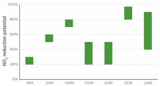
Figure 1.
Comparison of NOx reduction technology applied to ship [26].
In this study, the primary components of the development engine are designed with the layout of the SCR system, and the exhaust gas flow conditions as the basic design. The objective of the final SCR system is to optimize the components by conducting a performance evaluation on the reduction in NOx in relation to the experimental conditions in the actual engine by classifying the experimental variables and the performance parameters according to the experimental methods and procedures.
2. Apparatus and Methodology
2.1. Development Process of the Selective Catalytic Reduction System
Figure 2 shows the performance of the SCR system obtained from the basic design and the detailed design by comparing it with the numerical method and the temperature programming diagram (TPD) test results for the catalyst. The SCR system was obtained through the numerical analysis results optimized in accordance with the experimental variables by conducting a performance evaluation in the actual engine. After the actual design was achieved based on the exhaust gas and NOx of the target engine, the SCR system was optimized as a flow-charter, as shown in Figure 2. First, in the basic design, the major components of the development engine were designed according to the layout of the SCR system and exhaust gas flow conditions. The components in the SCR system were the urea dosing system design, urea nozzle, urea injection quantity, mixer, and SCR reactor. Next, a detailed design of all components were performed. The detailed designs were for the mixer, nozzle, and urea dosing control system, SCR reactor optimization, and soot blower. The final determination of the design was performed by component analysis, as shown in Figure 2 and Figure 3, by dividing the experimental and performance variables by the numerical analysis results.
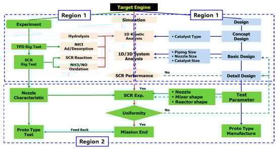
Figure 2.
Schematic of SCR system development process.
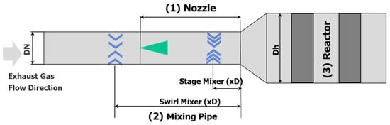
Figure 3.
Schematic of the development SCR system according to the variation in experimental parameters.
The final SCR system was divided into experimental and performance variables, and the performance of the reduction of NOx was tested according to the experimental conditions in the actual engine following the same experimental method and procedure. The performance optimization of the SCR system was performed through the experimental parameters, as shown in Figure 3. Table 2 shows the experimental parameters for the nozzle characteristics, mixer, and reactor geometry. The area ratio is (Dh/DN)2, implying the ratio between the mixing pipe (DN) and hydraulic diameter (Dh). Figure 4 shows the definition of spray angle in the multihole urea nozzle used. The space velocity (Equation (1)) represents the flow rate of the incoming exhaust gas divided by the volume of the catalyst, and indicates how many reactor volumes can be processed per unit time:
Table 2.
Experimental conditions for the nozzle and mixer, and reactor configurations.
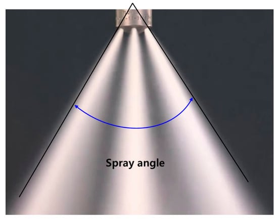
Figure 4.
The definition of spray angle for the multihole urea nozzle used.
2.2. Experimental Apparatus
Figure 5 shows a schematic of the development SCR system applied in a marine auxiliary generator engine, of which of the power is 720 kW. The SCR system shows the positions of the NOx sensor, temperature sensor, pressure sensor, and differential pressure sensor. At the end of the system development, data were obtained using a NOx sensor and a Fourier transform infrared (FTIR) analyser. The pressure, temperature, and NOx obtained according to actual engine load conditions were measured and compared simultaneously. Table 3 shows the specifications of the engine used in this study. A Horiba MEXA 9100 gas analyzer was used to measure the upstream and downstream NOx emissions. A NOx sensor was used to provide feedback information to the dosing control unit (DCU; urea dosing strategy) components such as the SCR controller. Additionally, AVL FTIR was used to monitor NH3 and NOx emissions at the tailpipe of the SCR reactor, as shown in Figure 5. Table 4 shows the experimental condition in this research.
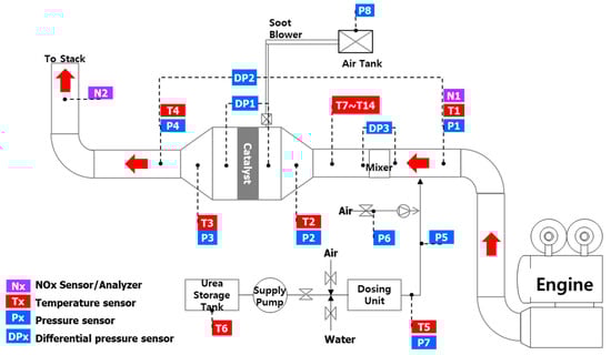
Figure 5.
Schematic of the marine engine and engine dynamometer.
Table 3.
Specifications of the test engine.
Table 4.
Engine test conditions.
3. Results
3.1. NOx Reduction Characteristics in Relation to Spray Angle and Distance of the Nozzle
Figure 6 shows the NOx reduction characteristics in relation to the injection angle of the nozzle. From the results, when the angle of the injection nozzle is 40°, the NOx reduction characteristic is excellent. Figure 7 shows the temperature distribution obtained from the temperature sensor installed in T7–T14, as shown in Figure 5. Figure 7b shows the temperature distribution over time from T7 to T14. Figure 7a shows the non-uniform distribution of temperature. The results in Figure 7b indicate that the injected exhaust gas and injected urea solution are mixed uniformly. From these results, we selected a urea nozzle with 40° angle.
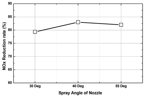
Figure 6.
Characteristics of NOx reduction rate in relation to the spray angle of the urea nozzle tip.
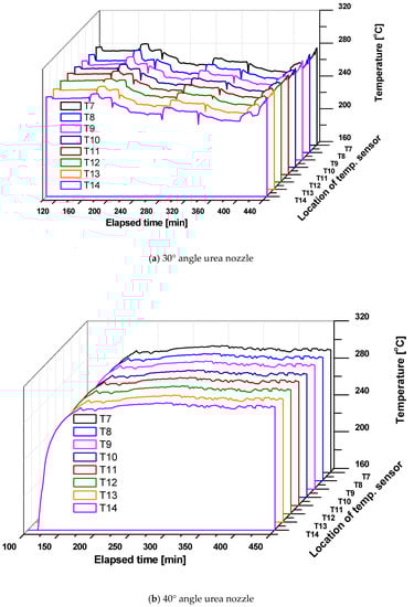
Figure 7.
Temperature distributions in accordance with the variations of a 30° and 40° urea nozzle.
Figure 8 shows the result of selecting the nozzle in Figure 7b and the NOx reduction characteristics according to the injection position of the nozzle. From the results of Figure 8, the nozzle is installed 5D away from the reactor inlet to the engine.
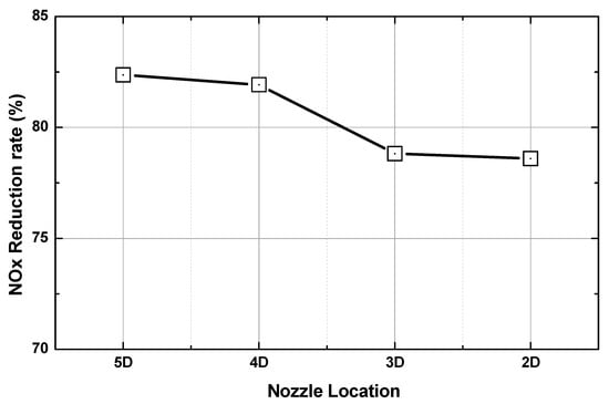
Figure 8.
Characteristics of NOx reduction rate in relation to distance from the urea nozzle.
3.2. NOx Reduction Characteristics in Relation to the Location of Stage and Swirl Mixer
Figure 9 shows the characteristics of the pressure loss and ammonia slip according to the ratio of the mixer type (stage mixer and swirl mixer), the area ratio of the reactor and the exhaust pipe, and the catalyst installation length. When the characteristics of pressure loss and ammonia slip were excellent, the position of the mixer of the xD (stage mixer) * 5D (swirl mixer), the area ratio of 4.2, and the catalyst length of 0.83D were superior. The shape, position, and reactor shape of the mixer obtained from this study were selected.
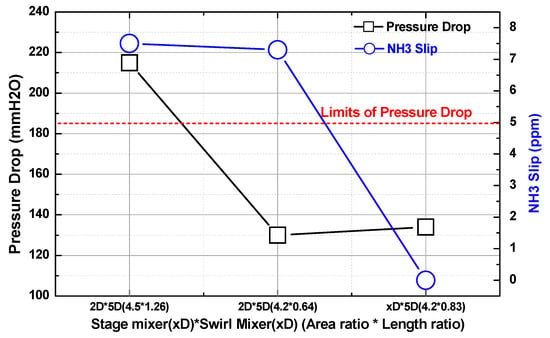
Figure 9.
Pressure decrease and NH3 slip characteristics in relation to mixer type and mixer location.
Figure 10 shows the distribution of NOx concentration measured at 64 points at the end of the SCR reactor according to the ratio of the exhaust gas inlet area to the catalyst inlet area. From this result, Figure 10b shows a uniform distribution of NOx concentration at the end of the reactor, while Figure 10a shows the eccentricity at one side.
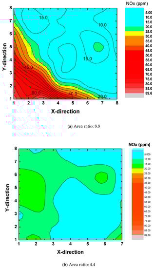
Figure 10.
NOx distribution in relation to the variations of 8.8 and 4.2 of area ratios.
3.3. Performance of NOx Reduction Rate in Relation to Maximum Continuous Rating Conditions
Figure 11 shows the results of pressure decrease, NOx reduction rate, and NH3 slip characteristics of the maximum continuous rating (MCR) operating conditions and space velocity. From these results, it was found that the space velocity of 8000 (1/h) indicates the best pressure decrease, NOx reduction rate, and NH3 slip characteristics.
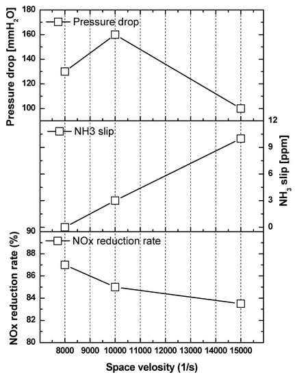
Figure 11.
Characteristic of pressure decrease, NOx reduction rate, and NH3 slip in relation to the variation in space velocity.
Figure 12 shows the NOx concentration in terms of NOx concentration and engine load obtained from the front end of the engine exhaust gas and the rear end of the SCR system in relation to the MCR conditions. The results of this study were 10.32 g/kWh at the end of the engine and 1.89 g/kWh at the end of the SCR system. This result satisfies the IMO regulation value of 2.40 g/kWh.
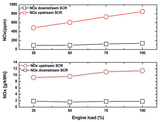
Figure 12.
NOx characteristic in relation to the variation in MCR conditions.
Figure 13 shows the NOx reduction rate and NH3 slip characteristics according to MCR conditions using the optimized SCR system. These results indicate that the reduction rate of NOx exceeds 80% in all MCR conditions. Finally, the SCR system developed in this study proves that the performance of the SCR system satisfies the IMO regulatory requirements.
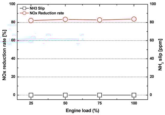
Figure 13.
Characteristics of NOx reduction rate and NH3 slip in relation to MCR conditions.
4. Conclusions
In this study, the primary components of the development engine were designed with the layout of the SCR system and the exhaust gas flow conditions as the basic design. The components in the SCR system were of a urea dosing system design, urea nozzle, urea injection quantity, mixer, and SCR reactor. Next, detailed designing of all components was performed. The detailed design created specific designs for the mixer, nozzle, and urea dosing control system, SCR reactor optimization, and soot blower. The results of this research are as follows:
- (1)
- Nozzles were selected considering the NOx conversion and NH3 uniformity characteristics according to the spray angles of the urea nozzles. Through the temperature distribution characteristics considering the spray characteristics of the sprayed urea, a uniform distribution of temperature, and reduced NOx were obtained when the spray angle was 40°.
- (2)
- To optimize the urea nozzle position, mixer position, and reactor aspect ratio, the NH3 slip was optimized for the total differential pressure of the system. The results of this study reveal that the swirl mixer was located 5D away from the reactor and the area ratio of the reactor was 4.2.
- (3)
- The NOx reduction rate and NH3 slip characteristics in relation to MCR conditions using the optimized SCR system indicated that the NOx reduction rate exceeded 80% in all MCR conditions. Finally, the SCR system developed in this study proved that the performance of the SCR system satisfied the IMO regulatory requirements.
Author Contributions
D.K. and C.L. conceived and designed the experiments; D.K. performed the experiments; C.L. analyzed the data; D.K. contributed reagents/materials/analysis tools; C.L. wrote the paper.
Funding
This study was supported by the development of key fusion technology of the industry–academia research cooperation cluster support project.
Conflicts of Interest
The authors declare no conflict of interest.
Acronyms
| EGR | Exhaust gas recirculation |
| SCR | Selective catalytic reduction |
| IEM | Internal engine modification |
| DWI | Direct water injection |
| HAM | Humid air motors |
| FEW | Fuel–water emulsion |
| LNG | Liquefied natural gas |
| DN | Pipe diameter |
| xD | Position of mixer located xD away from reactor inlet |
| Dh | Hydraulic diameter |
| TPD | Temperature programming desorption |
| DCU | Dosing control unit |
| FTIR | Fourier transform infrared spectrometer |
| MCR | Maximum continuous rating |
| MDO | Marine diesel oil |
| SV | Space velocity (1/h) |
| IMO | International Maritime Organisation |
References
- Heywood, J.B. Internal Combustion Engine Fundamentals, 1st ed.; McGraw-Hill: New York, NY, USA, 1988. [Google Scholar]
- Lee, C. Performance evaluation of a urea-selective catalytic reduction system in a marine diesel engine. Proc. Inst. Mech. Eng. Part M J. Eng. Marit. Environ. 2017, 231, 801–808. [Google Scholar] [CrossRef]
- Magnusson, M.; Fridell, E.; Ingelsten, H.H. The influence of sulfur dioxide and water on the performance of a marine SCR catalyst. Appl. Catal. B Environ. 2012, 111–112, 20–26. [Google Scholar] [CrossRef]
- Zheng, Y.G. The Study on a New Method for Flue Gas Denitration of Marine Diesel Engine; Dalian Maritime University: Dalian, China, 2012. [Google Scholar]
- Yu, W.X. Plasma Desulfurization and Denitrification and Its Application in the Study of Marine Diesel Engine Exhaust Treatment; Wuhan Textile University: Wuhan, China, 2013. [Google Scholar]
- Bunger, J.; Krahl, J.; Munack, A.; Ruschel, Y.; Schröder, O.; Emmert, B.; Westphal, G.; Müller, M.; Hallier, E.; Brüning, T. Strong mutagenic effects of diesel engine emissions using vegetable oil as fuel, Arch. Toxicol. 2007, 81, 599–603. [Google Scholar] [CrossRef] [PubMed]
- Busca, G.; Larrubia, M.A.; Arrighi, L.; Ramis, G. Catalytic abatement of NOx: Chemical and mechanistic aspects. Catal. Today 2005, 107–108, 139–148. [Google Scholar] [CrossRef]
- Forzatti, P. Present status and perspectives in de-NOx SCR catalysis. Appl. Catal. A Gen. 2001, 222, 221–236. [Google Scholar] [CrossRef]
- Forzatti, P.; Nova, I.; Tronconi, E.; Kuatov, A.; Thøgersen, J.R. Effect of operating variables on the enhanced SCR reaction over a commercial V2O5-WO3/TiO2 catalyst for stationary applications. Catal. Today 2012, 184, 153–159. [Google Scholar] [CrossRef]
- Chiker, F.; Nogier, J.P.; Bonardet, J.L. Sub-monolayer V2O5-anatase TiO2 and Eurocat catalysts: IR, Raman and XPS characterisation of VOx dispersion. Catal. Today 2003, 78, 139–147. [Google Scholar] [CrossRef]
- Emission Technology–MarQuip B.V. Exclusive Yacht Exhausts. Available online: https://www.marquip.nl/yacht-exhaust-systems/emission-technology/ (accessed on 6 March 2017).
- Vejlgaard-laursen, M. MAN Diesel & Turbo, Denmark. ‘Controlling Tier III Technologies. In Proceedings of the 28th CIMAC World Congress, Meeting the Future of Combustion Engines, Helsinki, Finland, 6–10 June 2016; p. 15. [Google Scholar]
- Wärtsilä Finland Oy. Wärtsilä Environmental Product Guide, 4th ed.; Wärtsilä, Marine Solutions: Vaasa, Finland, 2015. [Google Scholar]
- Assessments and Standard Division, Office of Transportation and Air Quality, U.S. Environmental Protection Agency. Use Testing Program for Heavy-Duty Diesel Engine and Vehicles: Technical Support Document; EPA420-R-05-006; United States Environmental Protection Agency: Washington, DC, USA, 2005.
- MARPOL Convention 73/78; Annex VI; IMO: London, UK, 2008.
- Park, J.K.; Oh, J.M.; Kim, H.I.; Lee, C. Combustion characteristics of MDO and MDO emulsion in automotive diesel engine. Trans. Korean Soc. Mech. Eng. B 2012, 36, 945–951. [Google Scholar] [CrossRef]
- Kim, M.; Oh, J.; Lee, C. Study on Combustion and Emission Characteristics of Marine Diesel Oil and Water-In-Oil Emulsified Marine Diesel Oil. Energies 2018, 11, 1830. [Google Scholar] [CrossRef]
- Verschaeren, R.; Schaepdryver, W.; Serruys, T.; Bastiaen, M.; Vervaeke, L.; Verhelst, S. Experimental study of NOx reduction on a medium speed heavy duty diesel engine by the application of EGR (exhaust gas recirculation) and miller timing. Energy 2014, 76, 614–621. [Google Scholar] [CrossRef]
- Bhaskar, K.; Nagarajan, G.; Sampath, S. Optimization of FOME (fish oil methyl esters) blend and EGR (exhaust gas recirculation) for simultaneous control of NOx and particulate matter emissions in diesel engines. Energy 2013, 62, 224–234. [Google Scholar] [CrossRef]
- Jafarmadar, S. Multidimensional modeling of the effect of EGR (exhaust gas recirculation) mass fraction on energy terms in an indirect injection diesel engine. Energy 2014, 66, 305–313. [Google Scholar] [CrossRef]
- Lee, C.H.; Lee, K.H. An experimental study of the combustion characteristics in SCCI and CAI based on direct-injection gasoline engine. Exp. Therm. Fluid Sci. 2007, 31, 1121–1132. [Google Scholar] [CrossRef]
- Lee, K.; Lee, C. An experimental study of the extent of the operating region and emission characteristics of stratified combustion using the controlled autoignition method. Energy Fuels 2006, 20, 1862–1869. [Google Scholar] [CrossRef]
- Lee, C.H.; Lee, K.H. An experimental study on the combustion and emission characteristics of a stratified charge compression ignition (SCCI) engine. Energy Fuels 2007, 21, 1901–1907. [Google Scholar] [CrossRef]
- Cimino, S.; Lisi, L.; Tortorelli, M. Low temperature SCR on supported MnOx catalysts for marine exhaust gas cleaning: Effect of KCl poisoning. Chem. Eng. J. 2016, 283, 223–230. [Google Scholar] [CrossRef]
- Guo, M.; Fu, Z.; Ma, D.; Ji, N.; Song, C.; Liu, Q. A short review of treatment methods of marine diesel engine exhaust gases. Procedia Eng. 2015, 121, 938–943. [Google Scholar] [CrossRef]
- Azzara, A.; Rutherford, D.; Wang, H. Feasibility of IMO ANNEX VI Tier III Implementation Using Selective Catalytic Reduction; International Council on Clean Transportation: Washington, DC, USA, 2014. [Google Scholar]
© 2019 by the authors. Licensee MDPI, Basel, Switzerland. This article is an open access article distributed under the terms and conditions of the Creative Commons Attribution (CC BY) license (http://creativecommons.org/licenses/by/4.0/).