


Abstract
This paper deals with the control of two five-phase permanent magnet synchronous motors (PMSMs), which are connected in series and operating at different speeds and torques. The topology under study is intended for use in an electrical naval propulsion system. The backstepping control strategy, which uses the Lyapunov stability concept, is employed to control the speed of the two machines considering the series connection of the PMSM stator windings. A comparative study, with respect to classical Vector Control (VC) using PI regulators, is provided to demonstrate the robustness of the proposed control strategies in both healthy and faulty conditions. Typically, dual PMSMs in series cannot operate in the degraded mode in the event of faults. This study optimizes their operation by adapting to such modes, including faults caused by symmetrical parameter changes or by an asymmetrical High Resistance Connection (HRC) in the stator windings, thereby ensuring continuity of service. The HRC is investigated and verified in one stator phase, in two adjacent stator phases and in two non-adjacent stator phases, as well as in a symmetrical HRC fault across all phases. Matlab-based simulation results validate the control design to achieve the desired performance and prove the effectiveness and the asymptotic stability of backstepping control for two series-connected 5-Փ PMSMs, thereby providing redundancy for the naval electric propulsion system.
1. Introduction
The needs of the maritime economy and the ecological transition require a major overhaul of ship propulsion systems to reduce their environmental impact and optimize operation and reliability [1]. Significant advancements have been realized by the electrification of the propulsion system to meet these needs. An electric drive-based propulsion system can be a three-phase Alternating Current (AC) machine or a multiphase AC machine (with more than 3 phases). However, multiphase machines, especially permanent magnet synchronous machines (PMSMs), have received considerable attention due to their inherent advantages, such as enhanced torque density, improved fault tolerance thanks to additional degrees of freedom and lower current per phase compared to traditional three-phase machines. These features make them highly suitable for applications requiring continuous operation, such as ship propulsion systems.
Electric propulsion architectures may incorporate various configurations, such as parallel independent propulsion lines, dual-motor shaft line arrangements, or series electric drive configurations where the motors share a common supply. Although series-connected machines are uncommon in the maritime sector, multiple configurations have been investigated for traction and aerospace systems in order to provide redundancy, reduce the number of converters required and enhance efficiency [2]. The series connection of multiphase machines has been studied in the context of both induction machines [2,3] and permanent magnet synchronous machines (PMSMs) [4,5,6,7] under various inverter fault scenarios.
A key challenge in conventional marine electric propulsion is the dependence of each propulsion line on its dedicated inverter. If an inverter fails, the associated motor-propeller unit becomes unavailable, resulting in an abrupt loss of thrust that can endanger the safety of the vessel during low-speed maneuvering or berthing operations. This study therefore proposes an alternative architecture in the form of a series-connected dual-PMSM configuration, which can maintain propulsion even in degraded mode. By supplying two five-phase PMSMs via a single five-leg VSI after the fault occurrence in one of the two inverters, the propulsion system can remain operational thanks to the possible series-connected configuration of the machines. In fact, this configuration provides a form of electrical redundancy by allowing continuity of operation using the remaining healthy inverter, without requiring additional power electronic hardware. The proposed topology offers a compact, cost-effective solution that enhances reliability and operational continuity. This concept is a promising direction for future marine propulsion designs, as integrated, fault-tolerant architectures could reduce system complexity while enhancing navigational safety and resilience.
Dual-motor drive configurations that are tolerant of short-circuit switches and open-phase faults can be used, as described in [2]. One solution is to use two six-phase PMSMs in an open-end winding configuration, supplied by an H-bridge. Unfortunately, constraints in mass, volume and cost make another solution, involving the series connection of the two machines supplied by one VSI, more attractive [2,3,4]. While the number of transistors and DoF decrease, they remain sufficient for fault mode operation, especially when the inverter-legs arrangement is reconfigured. Series-connected multiphase drives have been widely studied first for induction machines (IM) [4,5], and then for synchronous machines with sinusoidal and non-sinusoidal back-EMFs. Other studies have analyzed the performance of these drives following an inverter fault [2,3] and [6,7,8]. Thanks to a special coupling between the two machines called a ‘swapping connection’, the control of each machine is independent, as addressed in this paper.
From a control perspective, conventional controllers such as vector control (VC) using proportional-integral (PI) or integral-proportional (IP) have been widely used for multi-phase drive control [8]. VC remains the industrial standard for PMSM drives, making it the most meaningful baseline for evaluating the effectiveness and robustness of backstepping control. However, there are various disturbances and uncertainties such as parameter changes, neglected dynamics, friction forces and load disturbances that can significantly affect the overall performance of the drive system when using these controllers. Generally, linear control techniques may have limitations in effectively attenuating these disturbances [9]. To address these challenges, adaptive control is introduced in [10]. One efficient strategy is sliding mode control (SMC) [11,12,13,14,15,16]. SMC is a robust nonlinear control technique that does not require an exact understanding of the system structure or model parameters [7,8]. Furthermore, this technique has emerged as a promising solution for industrial systems thanks to its ability to adapt to load variations, its robustness, its insensitivity to unknown parameters and disturbances and its ease of implementation in practical scenarios. In [17], the authors proposed a modified SMC approach with fuzzy logic adaptation for an underactuated mechanical system. Unfortunately, one inherent issue with the conventional SMC is its tendency to exhibit chattering, characterized by high-frequency fluctuations in the controlled variables across various operational conditions [15,18,19]. To mitigate this effect, a commonly used method is to replace the switching function with a smooth function [13,20,21]. The use of saturation functions can reduce chattering, but it may also impact control precision [22]. Other advanced nonlinear control approaches have been proposed for the control of multiphase machines [23,24]. Fuzzy logic control [25,26], input-output linearization control [27] and a backstepping-based method with a new adaptation law to compute the unknown parameters of a hydraulic-mechanical nonlinear system have been introduced in [28]. This approach is implemented on an induction motor that is linear to achieve tracking of positions while compensating for uncertainties during motor operation [29].
Backstepping control offers numerous advantages, such as high precision, good system stability and transient performance. In the case of a five-phase IM drive with sinusoidally distributed windings, the direct torque control (DTC) uses only the largest vectors from the look-up table, which causes very poor performance, manifested by large stator current harmonics of low order. To overcome this limitation, the use of nonlinear backstepping control in a five-phase motor drive, as presented in [30] and experimentally validated, is suggested. It has been proven that BC provides high performance, fast tracking and an acceptable level of torque ripples, as well as high dynamics and excellent stability properties.
The BC technique performs well in both the transient and steady-state regimes. The basic idea of backstepping control is to render the equivalent closed-loop system as stable subsystems of order one, which are cascaded using Lyapunov theory to give them strength and global asymptotic stability [31,32].
In other words, it is a multi-step method, at each stage, a virtual command is generated to ensure the convergence of the system to its equilibrium state. This can be reached from Lyapunov functions that ensure the stability step by step of each synthesis step [33,34,35].
This paper investigates the application of a backstepping control method to two series-connected five-phase PMSMs used in a ship propulsion system. The two machines are supplied by a single VSI. To the best of the authors’ knowledge, this paper is the first to address the control of two series-connected multiphase machines using a backstepping-based approach. The main contributions of this work are summarized below:
- −
- The backstepping control laws are derived for two series-connected five-phase PMSMs. The formulation of this control strategy considers the electrical coupling inherent to the series configuration.
- −
- The proposed backstepping-based controllers are developed using a multi-stage design procedure, ensuring overall stability of the system and independent control of the two machines, even though they share the same phase currents.
- −
- The proposed control method is validated through simulations under various testing scenarios, enabling comprehensive analysis of different operational conditions, including a realistic scenario of nonlinear load characteristics, representative of ship propulsion dynamics.
The rest of the paper is organized as follows. Section 2 presents the modeling of two series-connected 5-Φ PMSMs with a single VSI. The details about the backstepping control strategy applied to the series-connected multiphase machine topology are addressed in Section 3. In Section 4, simulation tests regarding parametric variations are performed when symmetrical and asymmetrical high resistance connection is considered. Conclusions and perspectives are provided in Section 5.
2. Two Series-Connected Five-Phase PMSMs Topology
2.1. Conventional Marine Electric Propulsion Systems
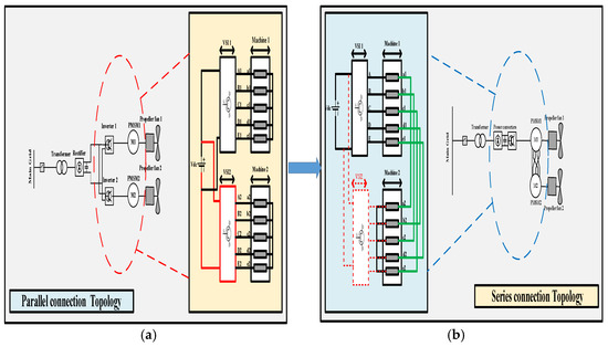
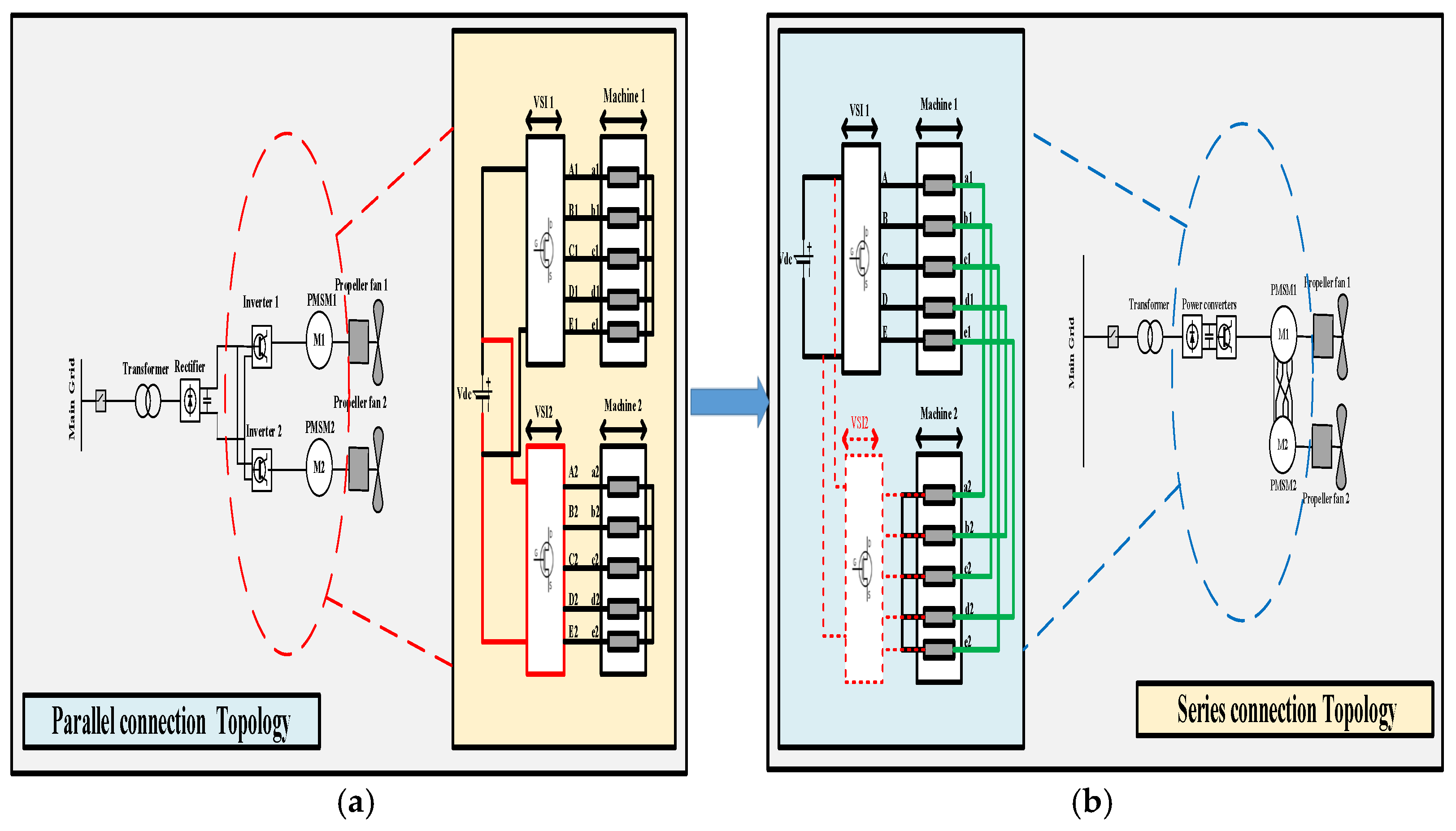
In conventional marine electric propulsion systems, each propulsion line is supplied by its own inverter in a parallel configuration. While this configuration provides good performance under normal conditions, the limitation of this connection topology is that, if one inverter fails, the corresponding propulsion line becomes completely unavailable. This results in a sudden loss of thrust and decreased efficiency in the hull system. This study explores a series-connected configuration in which two 5-phase PMSMs are supplied by a single five-leg voltage source inverter (VSI) [36]. This topology enables both machines to continue operating in degraded mode, as shown in Figure 1, where the propulsion line no longer depends on two separate power converters. Although the series connection introduces additional copper losses and slightly reduces efficiency, it provides a practical solution that ensures propulsion continuity without the need for costly, space-consuming redundant inverters. The proposed architecture enhances the reliability and survivability of ship propulsion, offering a viable alternative to traditional parallel configurations in classical electric propulsion systems.
Figure 1.
(a) Classical configuration, (b) Proposed configuration for the marine system. Solid red: healthy inverter mode, dashed red: failed inverter mode, green: transition to two series-connected PMSMs.
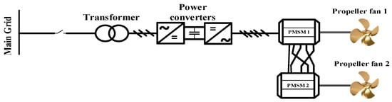
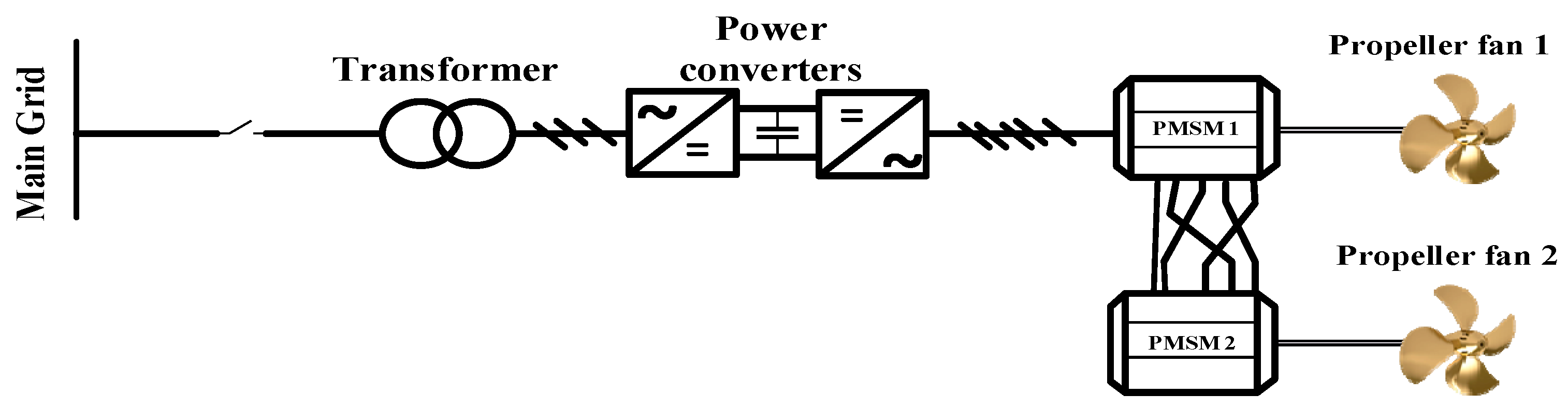
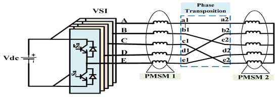
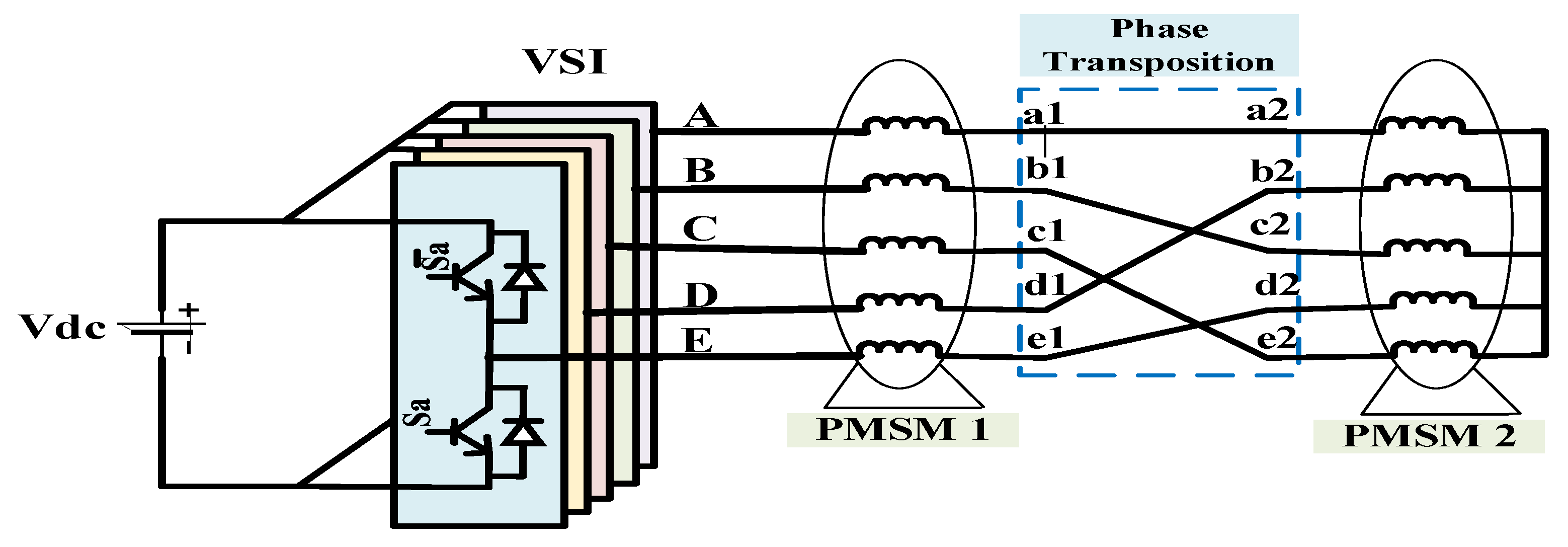
The main objective here is to control the speed and torque of the propellers driven by the five-phase PMSMs. As depicted in Figure 2, the considered configuration regroups two machines supplied by a single five-leg Voltage Source Inverter (VSI) and a DC source.
Figure 2.
Configuration of the ship’s electric propulsion system.
Typically, a DC source is provided by a power generation system driven by a marine diesel engine [1,35]. However, this study considers a constant DC-bus voltage supplying the electrical drive propulsion system, as shown in Figure 3. In addition, there is a special electrical connection between the two machines that allows them to be controlled independently [2,36].
Figure 3.
Considered topology of the two series-connected 5-Փ PMSMs supplied by single 5-leg inverter. : Inverter’s currents, : PMSM1’s currents, : PMSM2’s currents.
2.2. Two Series-Connected Five-Phase PMSMs Modeling
The two 5-Փ PMSMs are symmetrical with a spatial shift between any two successive phase windings equal to 2π/5. No coupling is provided for the windings of the first machine. However, a star coupling of the windings of the second machine is used. This series connection respects a particular phase transposition defined in [36,37] and shown in Figure 2. The model of one 5-Փ PMSM in the natural stator frame is given by [38,39]:
where is the total stator resistance of two series PMSMs, are the flux components and are the EMFs due to the permanent magnet rotor. According to the considered topology in Figure 2, the output voltages of the inverter referenced to the neutral point being the sum of the voltages across the windings of the two machines:
To deduce a simple control scheme, the decomposition in fictitious machines concept has been successfully applied to the multiphase drives [31,38]. The equivalent fictitious machines are obtained in (4) by applying the linear Concordia transformation given in (5).
Then the expressions of the inverter output currents are [8]:
The basic idea of the series connection is that the voltage component of PMSM1 (respectively, PMSM2) determines the inverter voltage component in the α-β frame (respectively, in the x-y frame) [33]. The equivalent model of the series connection of two 5-Փ PMSMs must be performed in the natural frame abcde, then in the α-β-x-y frame and finally in the d1q1d3q3 frame.
This form describes the steady-state representation of the two-motor series-connected 5-Փ PMSMs drive system in the dynamic reference frame [35]:
The equivalent model in d1q1d3q3 frame given in (9) can be obtained by applying park transformation (8) [2,36]:
where are the stator inductances of the main fictitious machines, respectively, of PMSM1 and PMSM2.
And are defined as stator inductances of the secondary fictitious machines, respectively, of PMSM1 and PMSM2.
are the electrical speeds, respectively, of PMSM1 and PMSM2.
are the amplitudes of the magnet flux, respectively, of PMSM1 and PMSM2.
Here, it should be underlined that, although the two PMSMs are connected in series and therefore share the same current, they are able to operate at different speeds and with different torques.
In fact, the control is developed by decomposing each real 5-phase machine in fictitious electrically decoupled 2-phase and homopolar machines, called “main machine”, “secondary machine” and “homopolar machine”. Each of these machines interacts with some ranks of harmonics as summarized in Table 1.
Table 1.
Harmonic mapping for each five-phase PMSM.
Naturally, these fictitious machines are decoupled and their components can be independently controlled.
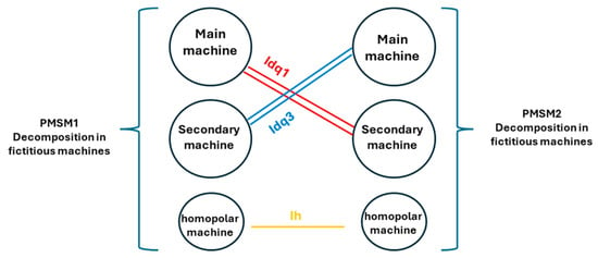
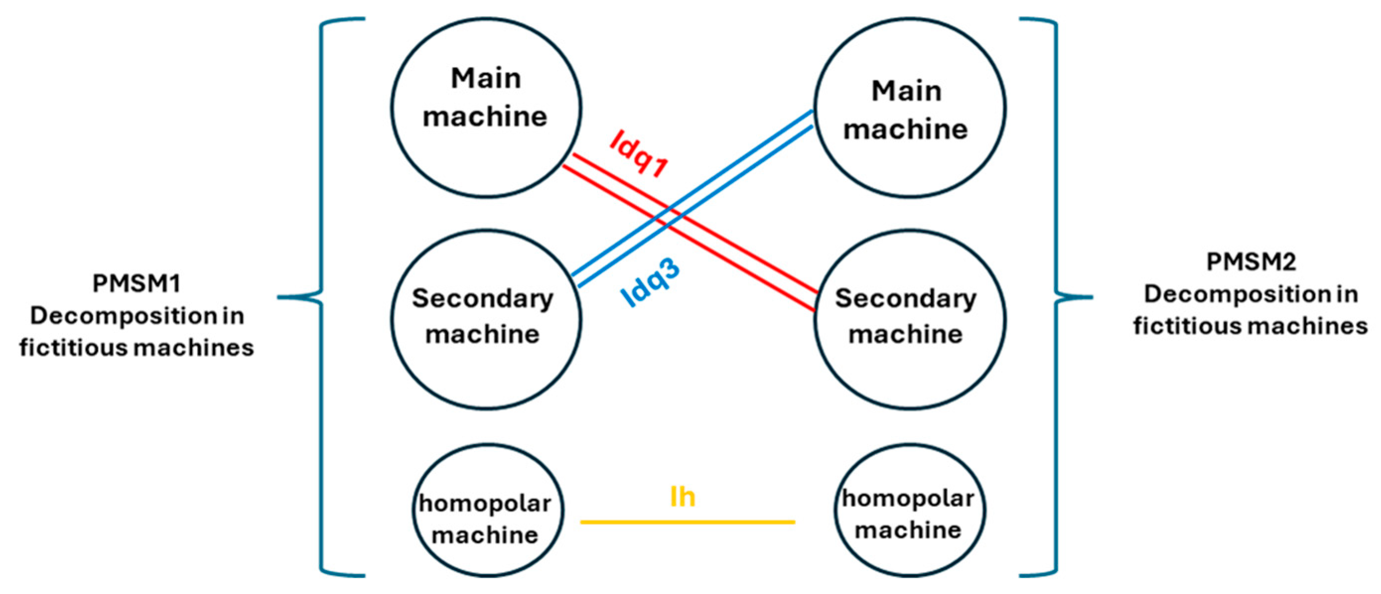
When considering the series configuration addressed in this paper, the corresponding fictitious machines are also connected in series, as illustrated in Figure 4.
Figure 4.
Series-connection of fictitious machines.
In addition, because the back-EMF of each PMSM is sinusoidal, the voltages, currents and flux of the fictitious “secondary machine” are null. This means that the first machine (PMSM1) is controlled in the (d1q1) frame while the second machine (PMSM2) is controlled in the (d3q3) frame. The control is fully independent and does not affect the stability or the overall performance of the system.
The mechanical equations for the rotating parts of the two machines are as follows:
where:
is the friction coefficient and are the propeller’s torques, respectively, connected to PMSM1 and PMSM2.
are the mechanical speeds, respectively, of PMSM1 and PMSM2. And are moments of inertia, respectively, of PMSM1 and PMSM2.
The electromagnetic torques and , respectively, generated by PMSM 1 and PMSM 2, are expressed in terms of state variables is given by (11):
where are the number of pair poles, respectively, of PMSM1 and PMSM2.
From (11), we can conclude that the electromagnetic torque developed by PMSM1 depends only on the current component of its main fictitious machine , while the torque produced by PMSM2 depends on the current component of the secondary fictitious machine . This results an independence control between the two series-connected machines [39].
3. Backstepping Control of Two Series-Connected 5-Փ PMSMs
The equivalent model of two series-connected 5-Փ PMSMs, under assumptions of linear magnetic circuits, is presented in a decoupled rotating frame d1q1d3q3 as described in (12) [30,31,38]:
The stator voltages are considered as control variables. The model (12) can be simplified as follows in (13) where the different functions to are expressed in (14):
The control objective is to ensure that the mechanical speed of PMSM1, , tracks its desired reference while for PMSM2, the mechanical speed follows its corresponding reference .
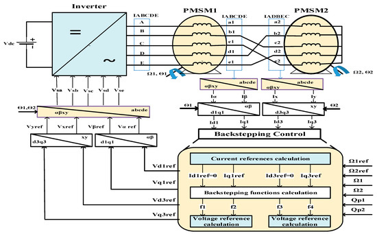
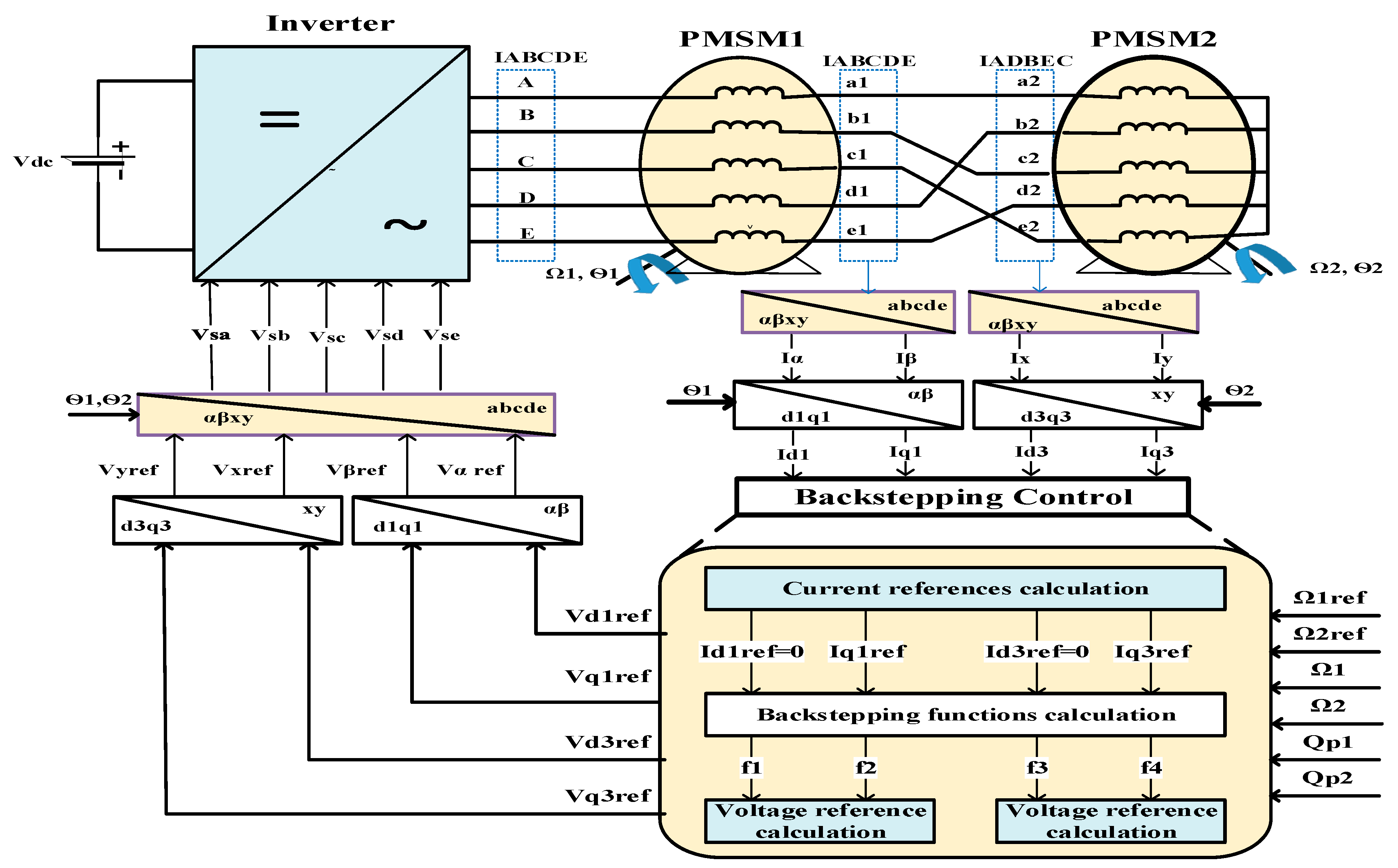
Figure 5 illustrates the backstepping control structure for a two series-connected five-phase PMSM supplied by a single VSI. The proposed strategy is based on various successive steps from reference current calculation and reference voltage calculation derived from defined backstepping functions and parameters. Following the principles of vector control, the direct-axis current in the plane and the direct-axis current in the plane are equal to zero, resulting in losses minimization [36]. The inputs of the backstepping controllers are the speed errors quantities and . These errors are used to calculate the reference value for the -axis current, , and the reference value for the -axis current, . Based on the speed and current errors, the controller generates the required stator voltage components , as shown in Equation (35).
Figure 5.
Block diagram of backstepping control applied to two series-connected PMSMs. : Inverter’s currents, : PMSM1’s currents, : PMSM2’s currents.
Backstepping Controller Synthesis
The basic principle of the backstepping control approach is to create linear equivalent subsystems of the closed-loop system in a cascade configuration based on the Lyapunov stability approach. This ensures robustness and global asymptotic stability. This multi-step method uses Lyapunov functions to stabilize each step sequentially. Each step of the process is designed to ensure convergence of the system to its equilibrium state. Below, the control based on the backstepping technique for 5-phase PMSMs, considering the series connection configuration, is introduced. The main purpose is to determine the reference stator currents and voltages that enable the machines to operate with minimum losses and maximum torque. Accordingly, the current components, and , are set to zero. Three steps are needed to derive backstepping control [26,27,28]:
- −
- Step 1—Computation of the reference stator currents
The first step consists of deriving the equivalent reference current components in decoupled frames and , , . Here, it is important to notice that the VSI is controlled so that each PMSM is controlled on an equivalent frame (PMSM1 is controlled in and PMSM2 is controlled in ).
The speed errors of the two machines are given by the following:
The derivative of (15) gives (16):
According to (13), we can rewrite (16) by completing the following:
The first Lyapunov candidate functions , associated, respectively, to PMSM1 and PMSM2 with speed errors defined in (15), are the following:
Using (15), the derivative of (18) can be given by the following:
and can be rewritten as follows:
where and should be positives in order to guarantee a stable speed tracking. Considering Equations (16), (17) and (20), the derivative of the machine’s speed errors can be given by the following:
This leads to obtaining (22) given by the following:
From (23), the reference stator currents can be deduced as follows:
where are defined by the following:
- −
- Step 2—Computation of the reference stator voltages
The second step consists of computing the reference voltages based on the reference currents provided by the first step. The current errors are defined by the following:
Considering Equations (24) and (25), the relationships in (26) become equal to the following:
with this definition, (21) can be expressed as follows:
The time derivative of (27) yields the following:
Substitutes (24) into (27) gives the following:
It can be seen here that (30) includes the stator voltage. This can be determined through the definition of a new Lyapunov function based on speed and current errors:
The derivative of (31) is given by the following:
By substituting (27) and (30) in (32), we can obtain the following (33):
Setting the quantities in brackets in (33) to zero would result in the derivative of the Lyapunov function (32) being negative definite.
The stator voltages are then deduced as follows:
where , , and are positive quantities selected to guarantee a faster dynamic of the stator currents and rotor speeds. Then, (29) can be expressed as follows:
To show the boundedness of all states, we can rearrange the dynamical equations from (15) to (36) as follows:
where the matrix is defined by the following:
- −
- Step 3—checking the stability of the backstepping control
Here, it should be noticed that the stability analysis and verification are realized based on an algorithm developed on MATLAB 2023a. This step is important since it validates the control parameters proposed (, , ) to achieve our desired performance metrics under realistic conditions. The parameters are selected as a function of machine parameters and are defined in (25). Regarding the matrix ℜ, it must be proven to be a Hurwitz matrix, which confirms that all system states remain bounded. To prove this with the proposed parameters (, , ), the following conditions must be satisfied [26]:
- -
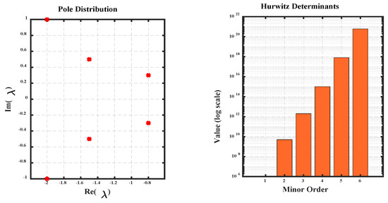
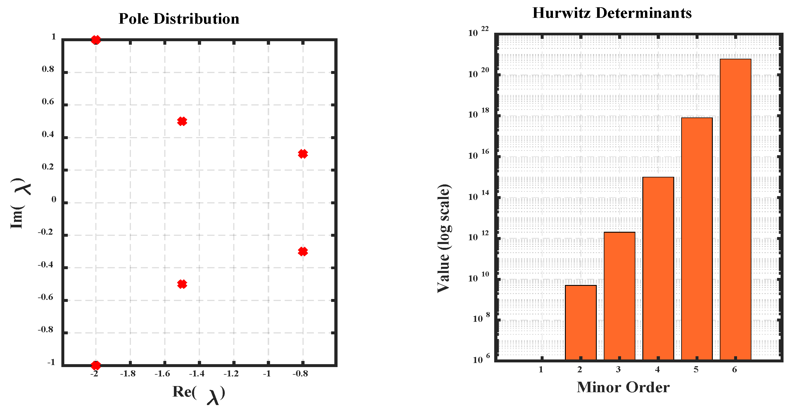
- The condition for the eigenvalues, where all the real parts of the eigenvalues, , of ℜ are strictly negative: e () < 0 for all . After an algebraic calculation, we verify that all the eigenvalues of ℜ with the control parameters proposed have strictly negative real parts, and this is shown in Figure 5. That is, prove that this condition is verified.
- -
- Sylvester criterion must be validated using the characteristic polynomial of the matrix ℜ given in (39) [27]:where are coefficients of the characteristic polynomial, . The polynomial matrix is given by the following (40):
- -
- The polynomial matrix H in (40) must have positive polynomial minors: the stability conditions for the polynomial matrix H obligate that all must be positive. Also, all the leading principal minors (determinants of the upper left submatrices) of the polynomial matrix must be positive. This is validated in Figure 6.Figure 6. Stability conditions.
After an algebraic calculation, we verify that all and principal minors of H are positive by verifying the two conditions, which prove the boundedness of all the states. This ensures the asymptotic stability of the backstepping control, where the system returns to the equilibrium state despite disturbances. In fact, the state of oscillatory and divergence modes does not exist because eigenvalues are not nullified or positive, and this highlights the stability of the system behavior.
In the next section, based on simulation results, the asymptotic stability and the robustness of the backstepping control applied to two series-connected PMSMs are verified.
4. Simulations and Results
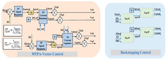
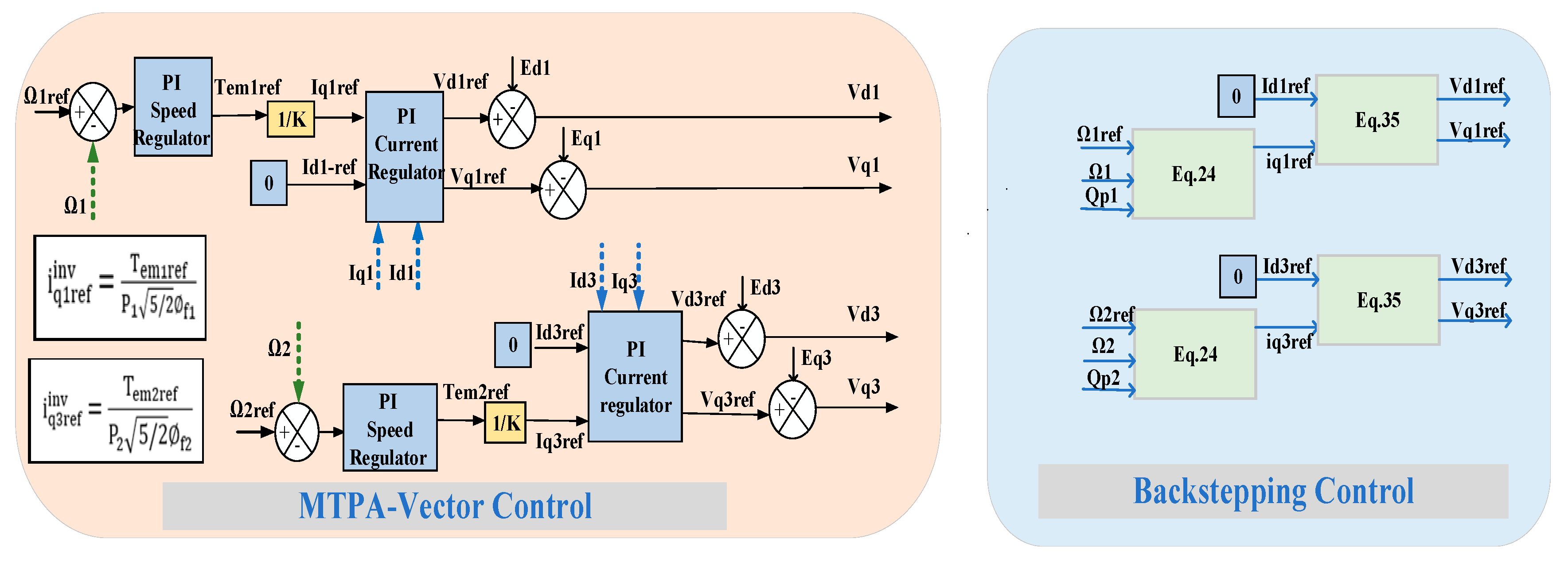
A comparative analysis is presented in this work. It is based on MATLAB 2023a/Simulink software and considers series-connected PMSMs controlled using either a backstepping strategy or a vector control strategy. Figure 6 shows the block diagrams of MTPA-based VC and BC.
The MTPA-based vector control strategy employs PI speed regulators that generate the reference torque, as illustrated in Figure 7. This approach facilitates the calculation of optimal current references that maximize the developed torque while minimizing Joule losses [40,41,42,43,44]. Consequently, the maximum torque per ampere condition is ensured, leading to the generation of optimal voltage references for the inverter drive. However, the BC method relies on non-linear analytical expressions to compute stable current and voltage references [37,45].
Figure 7.
Control strategies considered for comparative analysis.
The parameters used for the electric propulsion system simulation are summarized in Table 2.
Table 2.
Technical data of the used 5-Փ PMSM (PMSM 1 and PMSM 2).
The proposed control method is validated under various testing scenarios, enabling comprehensive analysis of different operational conditions, including a realistic scenario of nonlinear load characteristics, representative of ship propulsion dynamics.
4.1. Scenario 1: Test of the Proposed Control Method Under Transients Due to Speed Changes
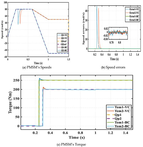
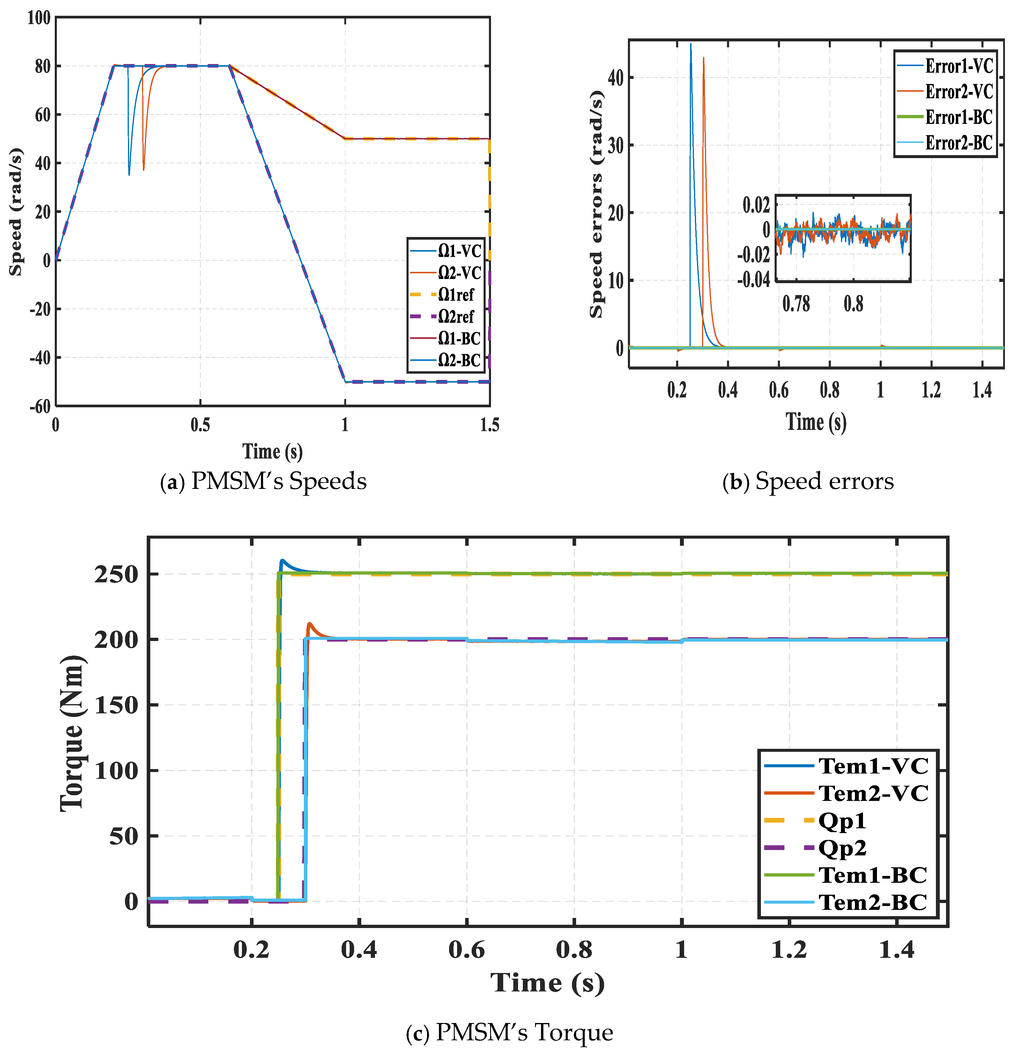
For this scenario, distinct reference speed trajectories are imposed on both machines under nominal load conditions. Initially, the first machine is subjected to a positive ramp starting at t = 0 s, reaching 80 rad/s at t = 0.2 s, while the second machine follows the same positive ramp over the same interval.
At t = 0.6 s, the reference speeds become constant, equal to 50 rad/s for PMSM1. At t = 0.7 s, the speed of PMSM2 becomes equal to −50 rad/s.
Both machines are subjected to a constant load torque. PMSM1 operates under a peak torque of 250 Nm at t = 0.25 s, while PMSM2 is loaded with 200 Nm at t = 0.3 s.
This operating profile enables us to verify that both machines accurately track imposed speeds and torque references independently and to assess the robustness of the control strategies under transient and steady-state conditions.
Figure 8a shows that both machines accurately track their imposed reference speeds without significant deviation, even during load change. This is confirmed in Figure 8b, where the relative speed error remains below 0.0006 rad/s for the BC, whereas it reaches up to 45 rad/s with MTPA-VC. These results highlight the superior tracking performance of BC compared to VC for different operation modes.
Figure 8.
Comparative speed control between VC and BC controllers in healthy mode.
4.2. Scenario 2: Test of the Proposed Control Method Under Transients Due to Torque Changes
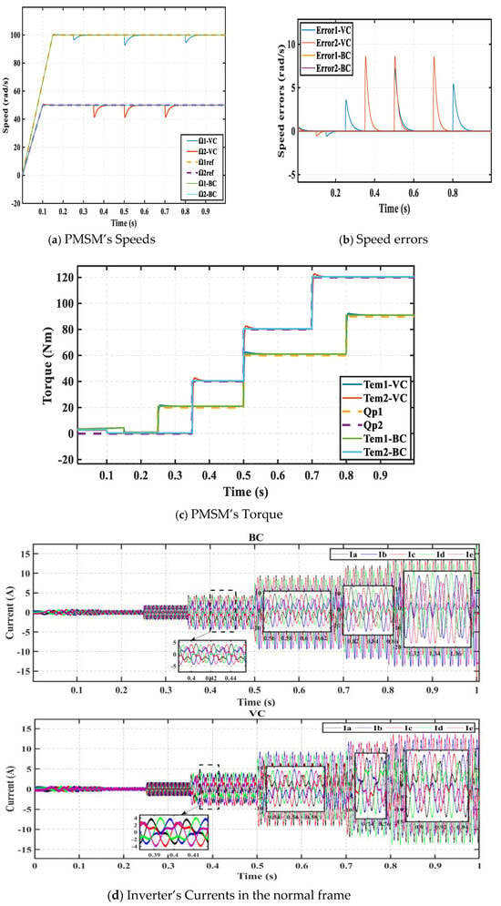
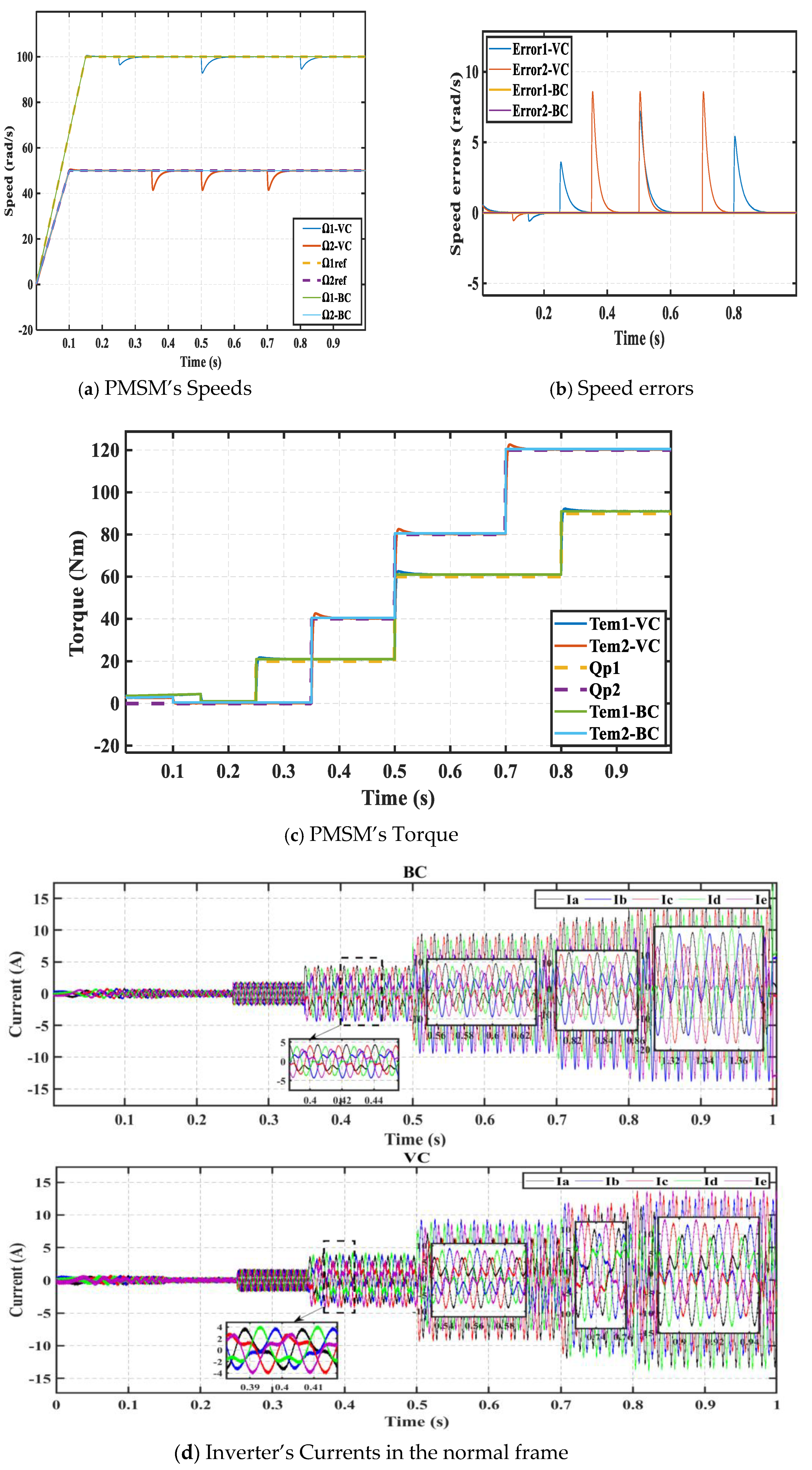
The main objective of this scenario is to control the series connection topology by fixing constant speeds equal to 100 rad/s for PMSM1 at t = 0.15 s and to 50 rad/s for PMSM2 at t = 0.1 s. Both machines started with no load.
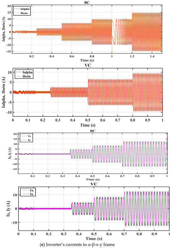
Then, a load torque equal to 20 Nm is applied to PMSM1 at t = 0.25 s and increases to 60 Nm and 90 Nm at t = 0.5 s and t = 0.8 s, respectively. For PMSM2, a different profile of load torque is applied at t = 0.35 s and is equal to 40 Nm. After that, it became 80 Nm at t = 0.5 s to reach 120 Nm at t = 0.7 s. Figure 9 presents the response of both machines to this scenario. Good results are shown, especially using BC with low torque errors and speed errors.
Figure 9.
Comparative Torque control between VC and BC controllers in healthy mode.
4.3. Scenario 3: Test of the Proposed Control Method Robustness Under Electrical Parameters Variation
The main objective of this scenario is to assess the sensitivity of the two control strategies against the symmetric resistance variation (SRV) and the symmetric inductance variation (SIV) of the PMSMs under study, at low speed and high torque.
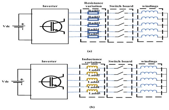
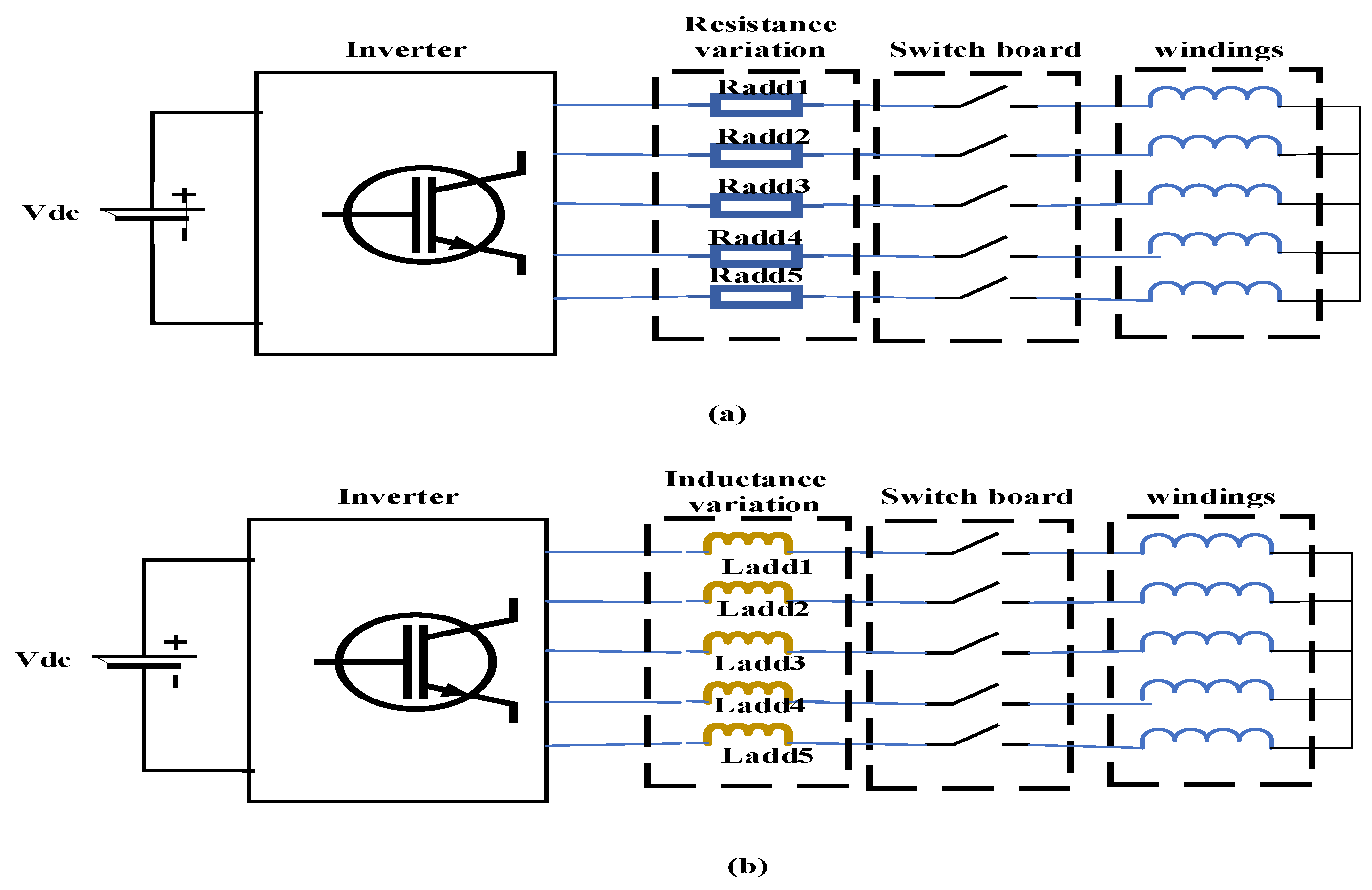
Figure 10 presents the principle of parametric variation applied to PMSM2 by symmetrically adding a resistance (Radd) or an inductance (Ladd) in the stator windings in order to test the effect of the parametric variation on the series connection topology and the dynamics of control strategies via these disturbances [40,41,45,46,47,48,49].
Figure 10.
(a) Resistance variation applied in the stator windings; (b) Inductance variation applied in the stator windings.
The analysis starts with an SRV, where the resistance variation is applied equally to all phases in PMSM2.
This condition preserves the inverter current signature but reduces its amplitude due to the high resistance value.
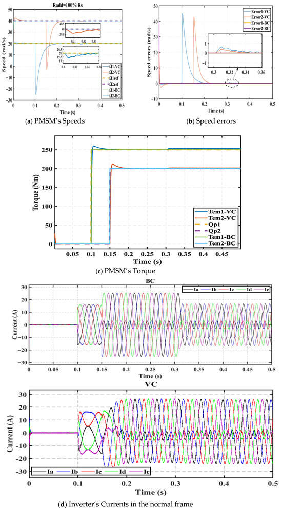
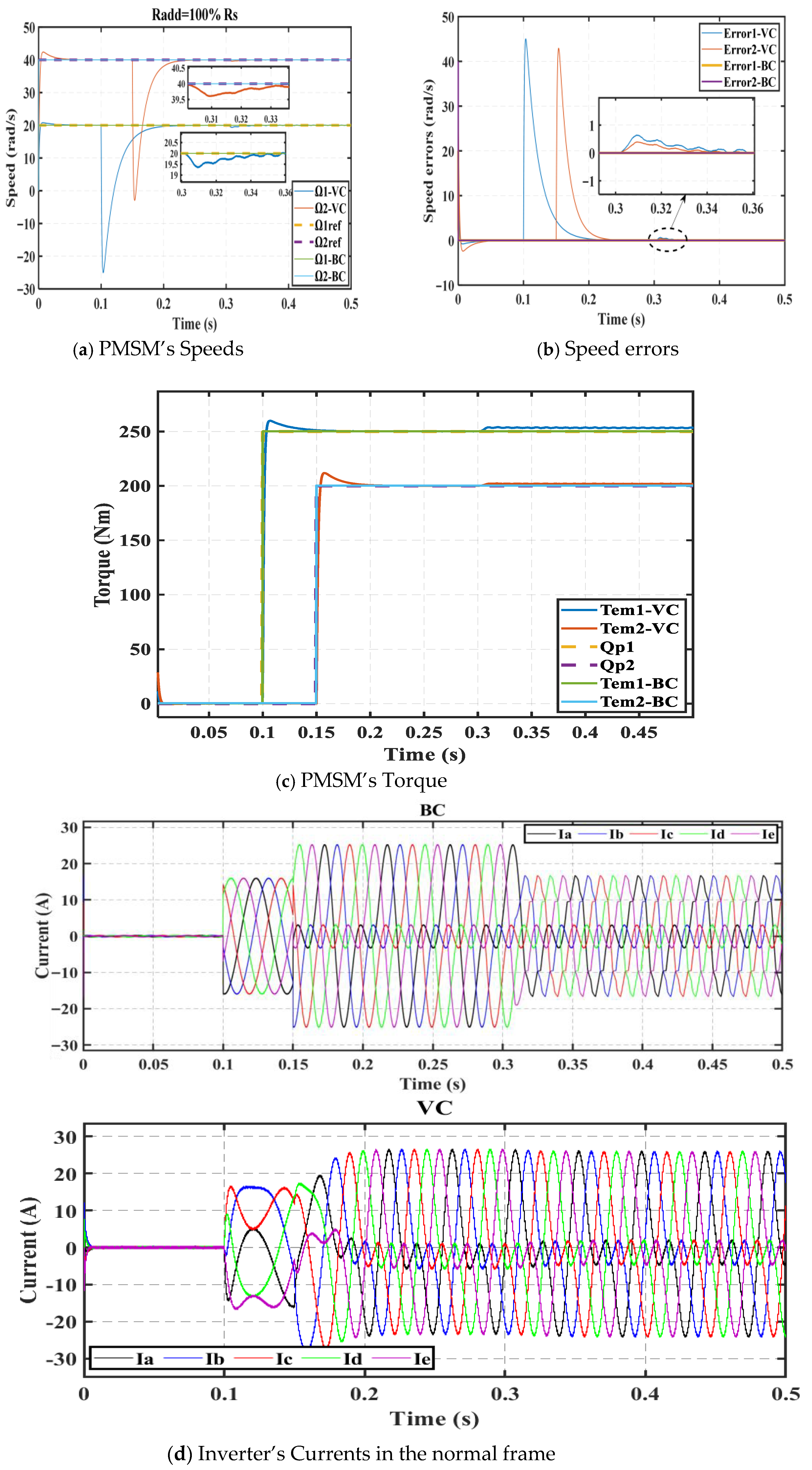
Simulations are tested for Radd = 100% Rs in Figure 11 equally to all phases at t = 0.2 s. The choice of different speeds for each machine aims to prove the independence of control between them.
Figure 11.
Comparative study between VC and BC controllers under symmetric resistance variation with Radd = 100 Ω.
The reference speeds are chosen equal to 40 rad/s for PMSM1 and equal to 20 rad/s for PMSM2. The torques are fixed equal to 250 Nm at t = 0.1 s for PMSM1 and equal to 200 Nm at t = 0.15 s for PMSM2. A good tracking of speed and torque references is observed in Figure 11.
By testing the sensitivity of the control strategies under low speeds and high loads, it is observed that BC gives a better response than VC despite the parametric variation that affects the current regulation [45,49].
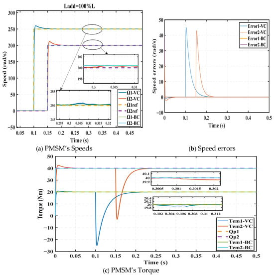
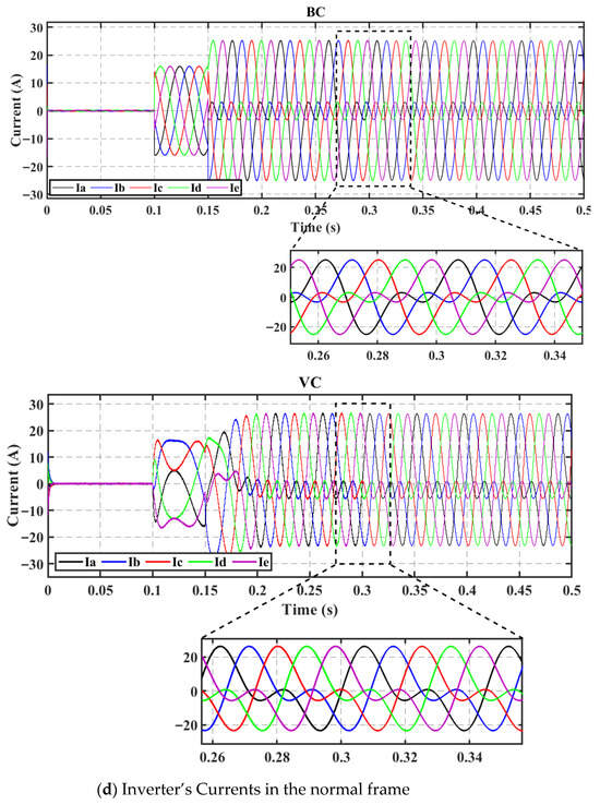
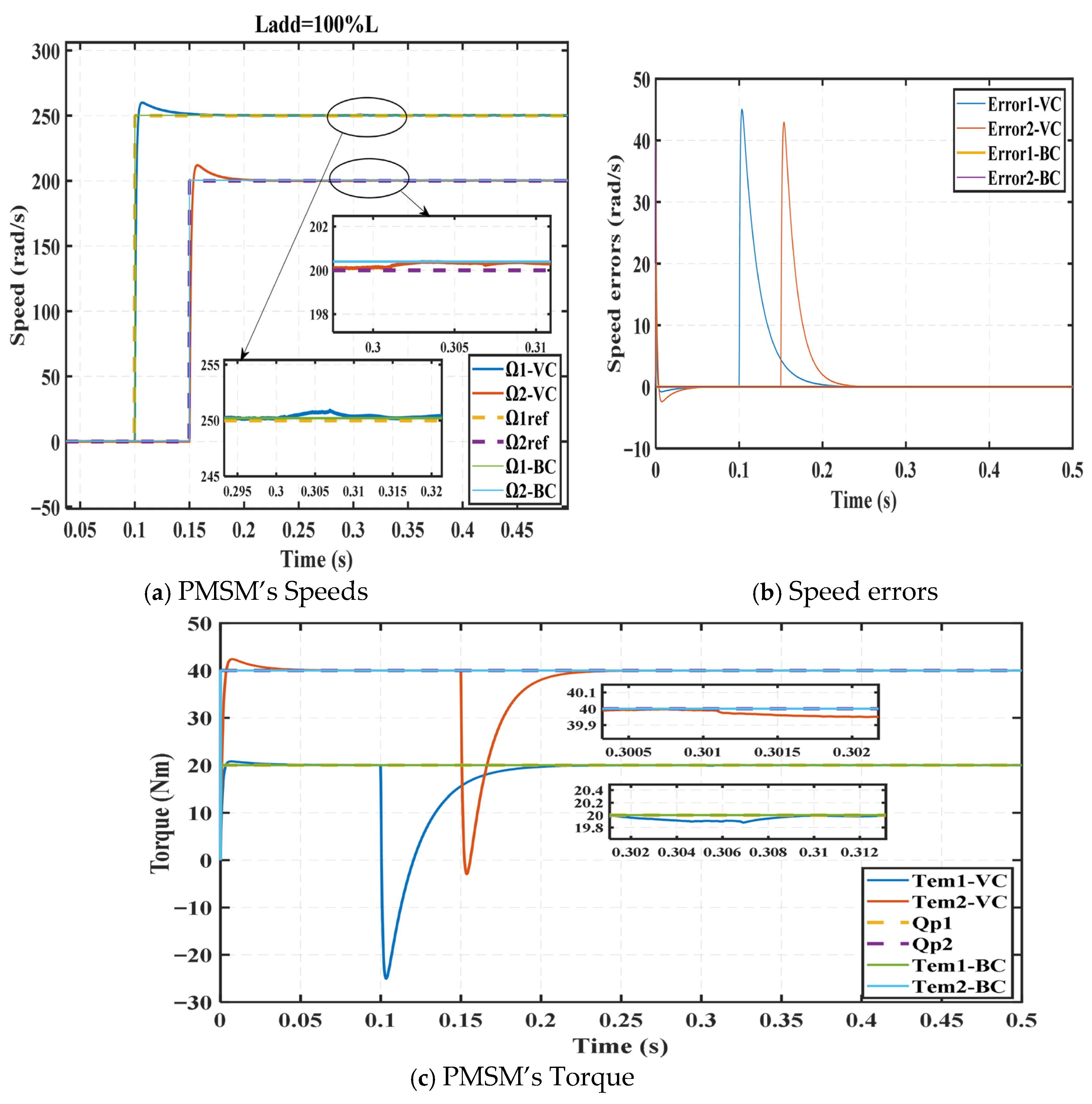
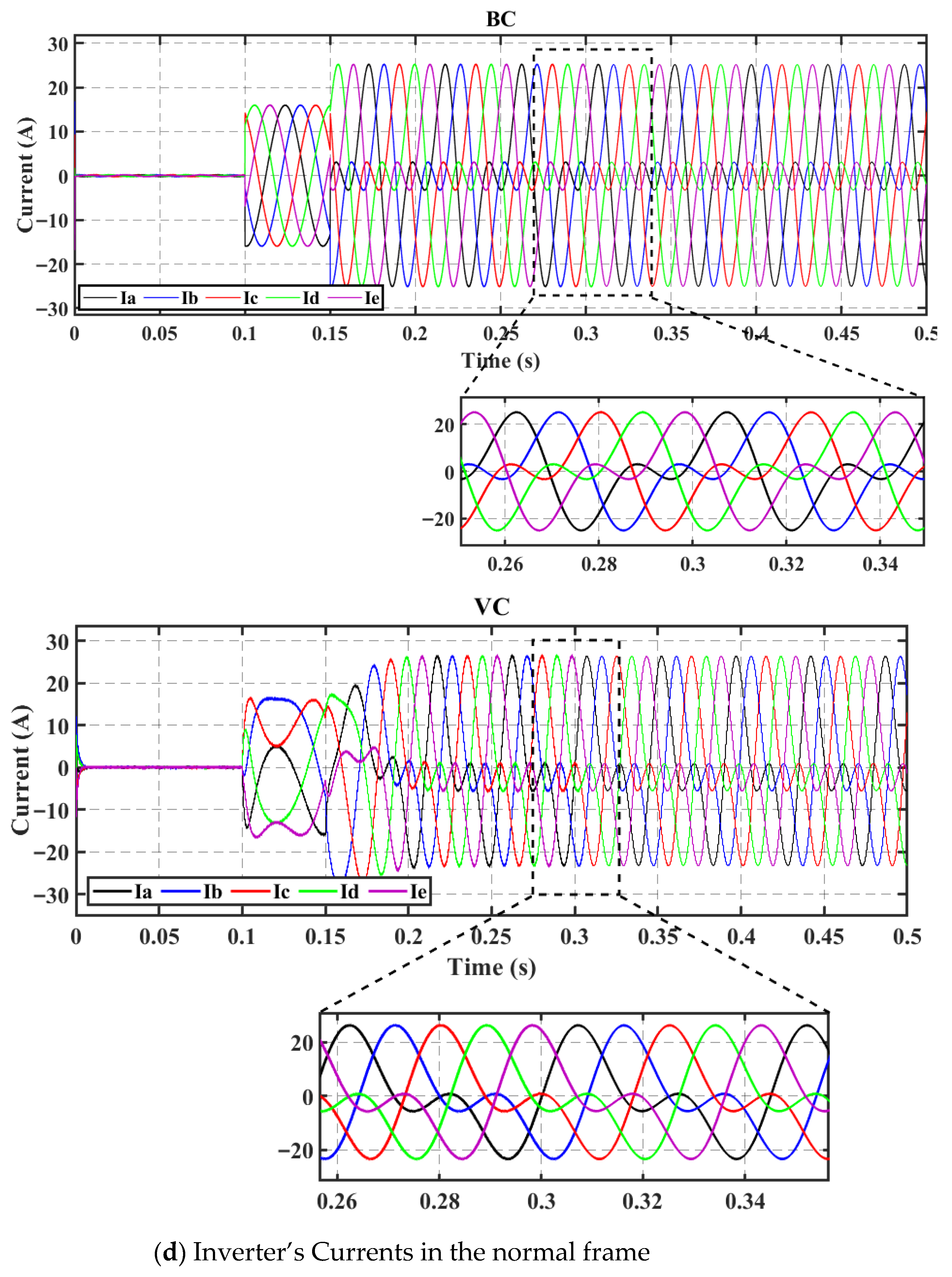
Regarding the SIV, simulations are obtained for Ladd = 100% L as illustrated in Figure 12. The inductance change is applied for all phases at t = 0.2 s. The inductance variation generally reacts as a classical low-pass filter by improving current quality [46].
Figure 12.
Comparative study between VC and BC controllers under symmetric inductance variation with Ladd = 100 H.
In Figure 12, it is depicted that the parametric variation in PMSM2 also affects PMSM1, caused by the coupling between them despite the independence of the control.
4.4. Scenario 4: Test of the Proposed Control Method Robustness Against High Resistance Connection Degradation
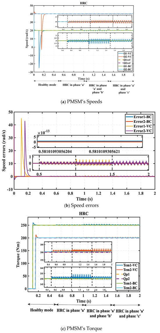
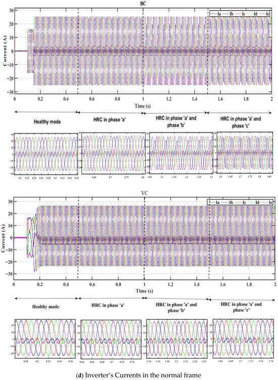
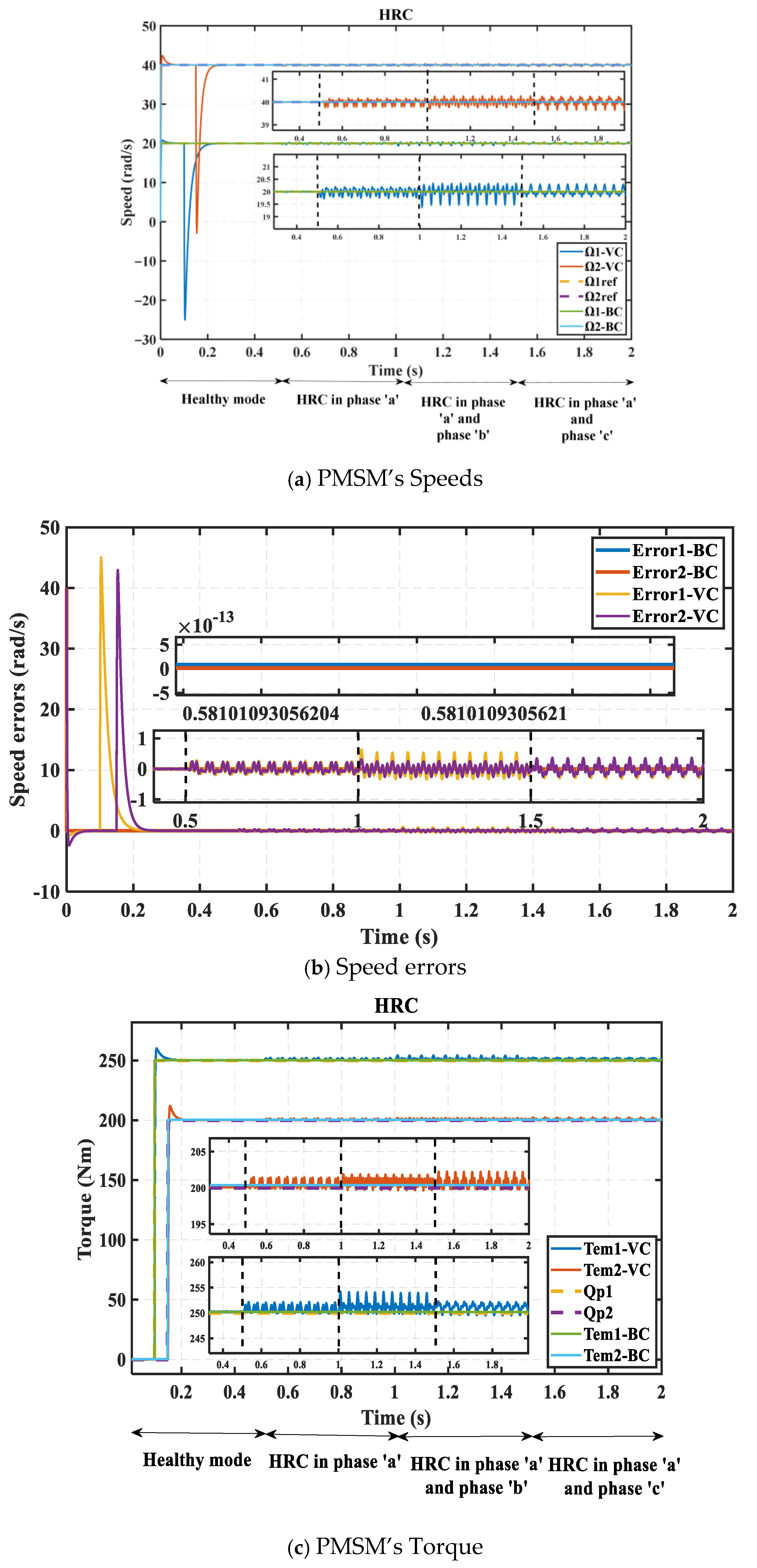
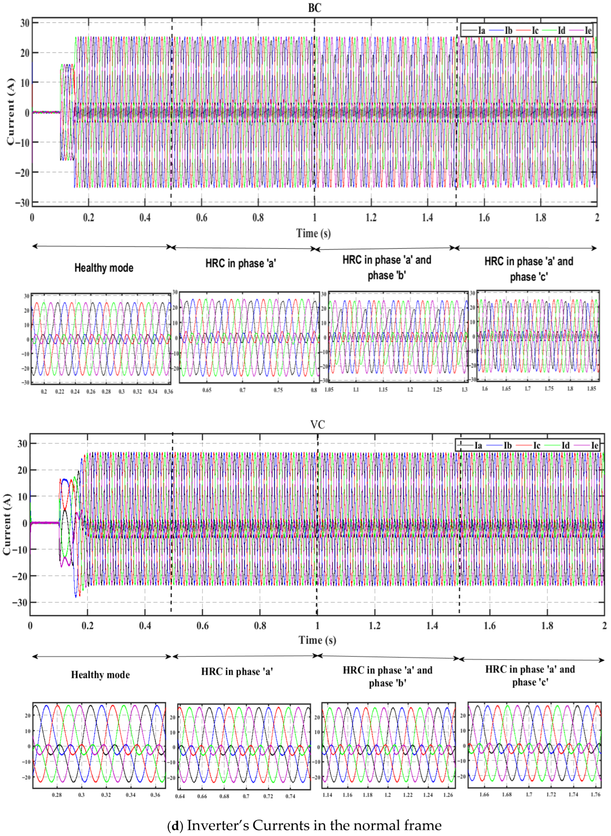
This scenario investigates the High Resistance Connection (HRC), which is a severe fault that can cause significant damage to electrical machines [50,51,52]. The series connection topology under this fault condition is analyzed in this section for HRC occurring in a single phase as well as in dual phases, whether adjacent or non-adjacent. The results obtained for this test are illustrated in Figure 13.
Figure 13.
Sensitivity of control techniques VC and BC to HRC at low speed and high torque.
The speeds of PMSM1 and PMSM2 are fixed at 20 rad/s and 40 rad/s, respectively. The torques are set to 250 Nm for PMSM1 and 200 Nm for PMSM2. The HRC occurring in PMSM2 also affects the speed and torque responses of PMSM1, as shown in Figure 13a–c, despite the independent control of both machines. In contrast, a single-phase HRC introduces significant harmonic distortion. For the HRC scenario, the speed errors presented in Figure 13b show that the BC strategy yields very low errors compared to the VC strategy, where speed errors reach up to 45 rad/s, which is considered a high error. Furthermore, HRC faults involving two adjacent phases are more severe than those involving two non-adjacent phases.
As a linear control strategy, the VC is unable to compensate for the HRC degradation. In contrast, the BC, as a nonlinear control strategy based on Lyapunov stability laws, dynamically adjusts the voltage references and distributes the control effort between the machines while maintaining a balanced response.
The results obtained for the series-connected configuration show that introducing an asymmetric HRC in the stator windings effectively mimics the behavior of a partial phase open-circuit fault. Consequently, the control system is forced to operate in a degraded mode, despite the limited degrees of freedom available in the inverter to manage such fault conditions. The HRC case clearly demonstrates degraded performance and its impact on both machines, providing a realistic representation of fault-induced operation. These observations emphasize the importance of investigating this scenario for the series connection topology, as it reveals the system’s sensitivity to winding asymmetries and their implications for fault tolerance.
Therefore, the simulation results confirm that the BC strategy provides enhanced robustness and superior dynamic performance in the series connection topology with a single VSI compared to the MTPA-VC approach.
4.5. Scenario 5: Test of the Proposed Control Method Robustness for a Realistic Scenario Representative of a Ship with Nonlinear Load Characteristics
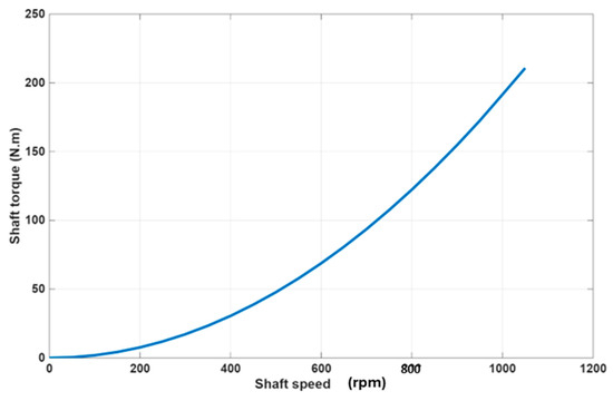
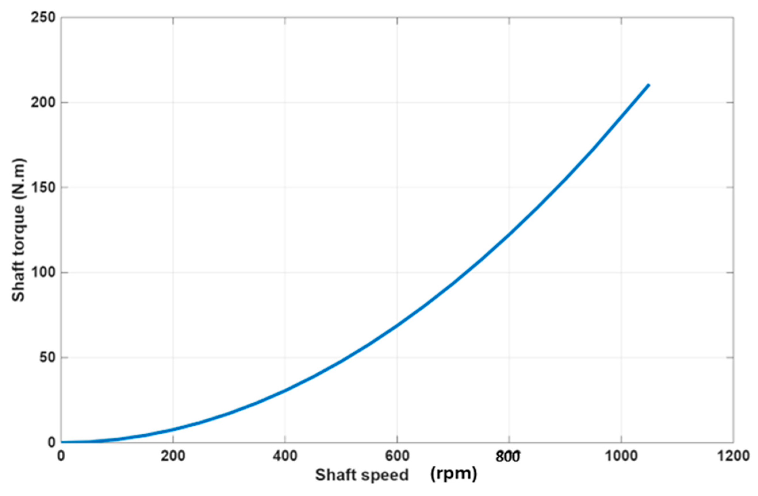
This scenario considers nonlinear load characteristics that represent the ship propulsion dynamics, as shown in Figure 14. This profile is derived from a nonlinear shaft–propeller–ship model that has already been published and employed in the research paper [44].
Figure 14.
Nonlinear ship load characteristic considered in the simulation.
It should be noted that, although the simulation results are presented for a small ship with low propulsion power, the proposed configuration, as well as the proposed nonlinear control strategy, can be readily extended to large ships with high propulsion power. By coupling this model with the PMSMs, the simulation can accurately reproduce the interactions that occur during the real operation of the ship.
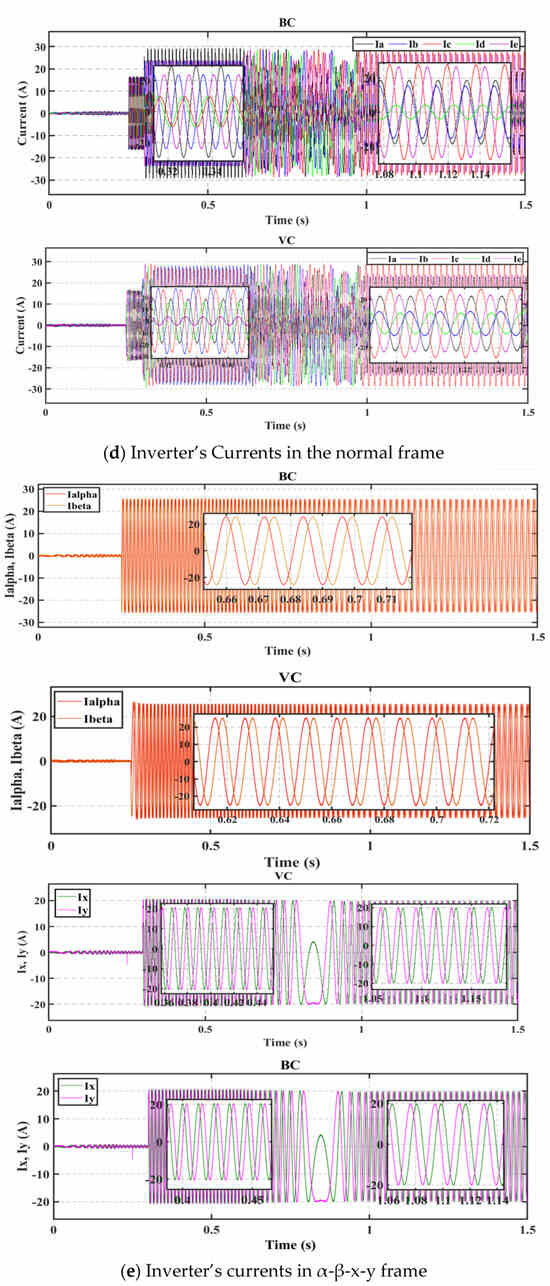
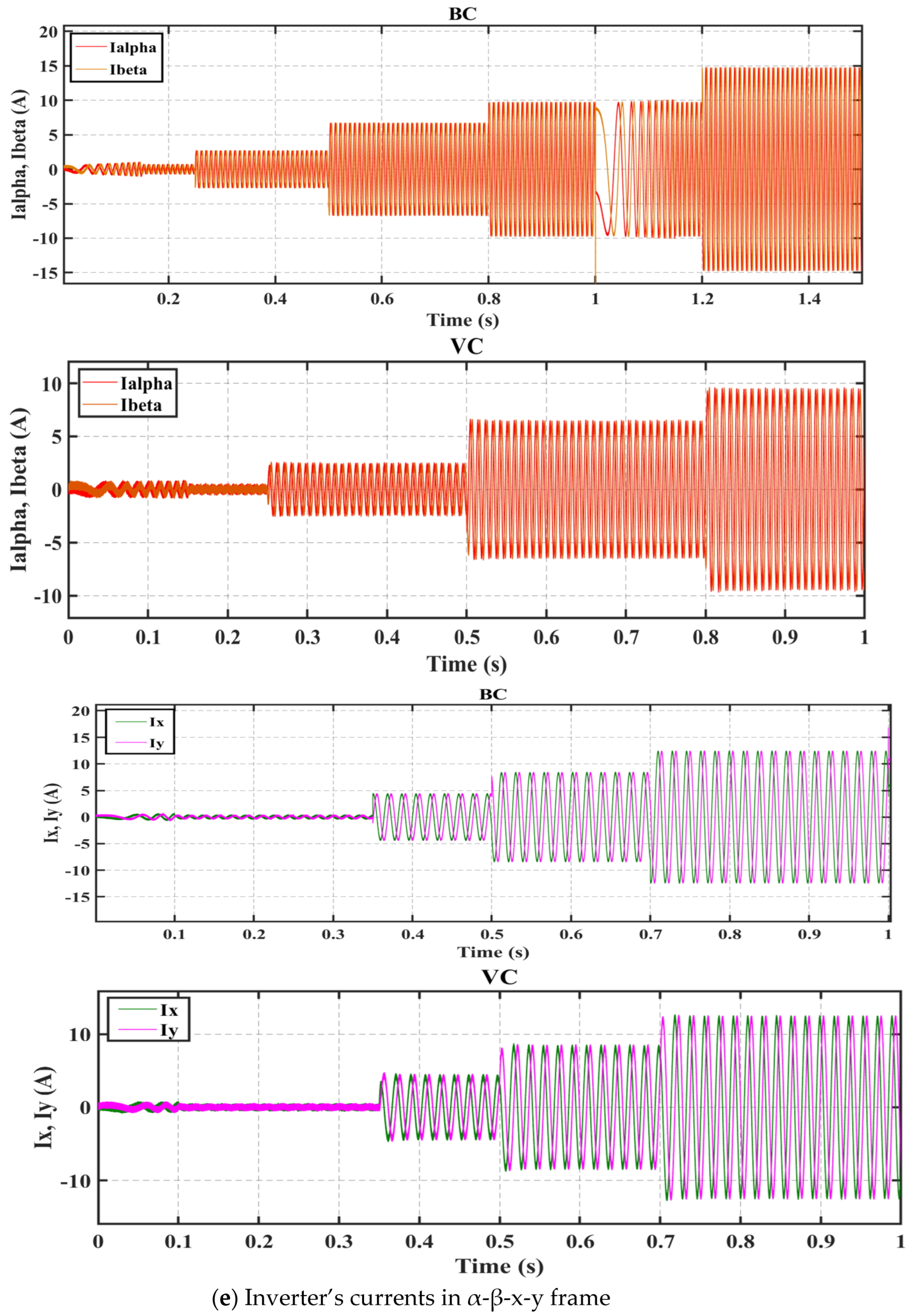
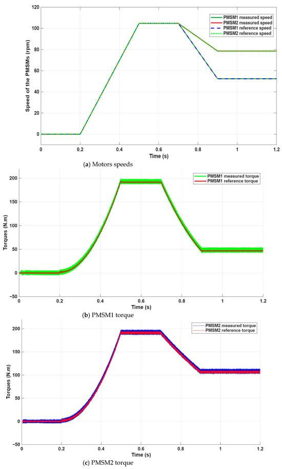
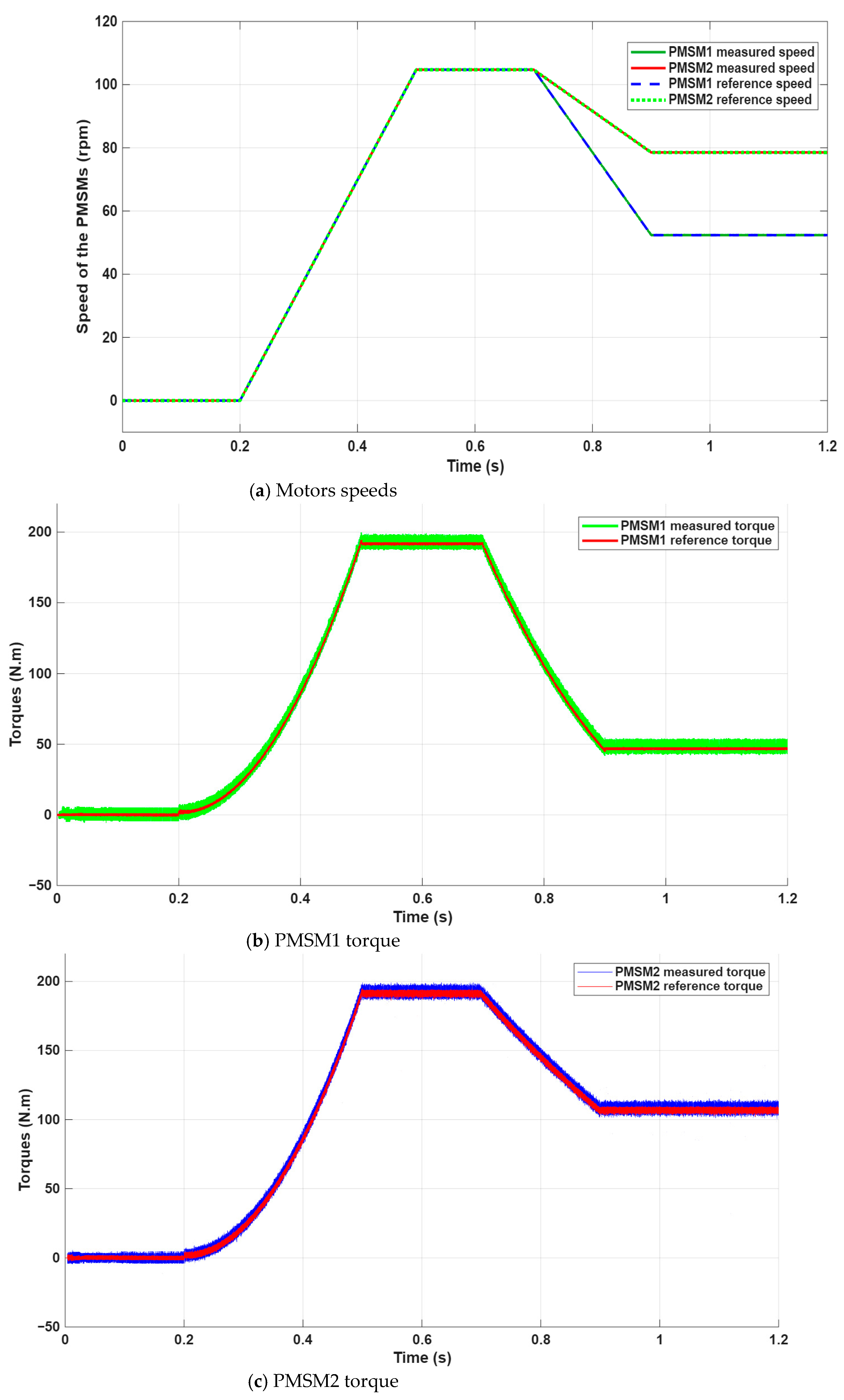
Figure 15 shows the time-domain waveforms of the machine speeds, torques and currents. The control strategy considered in this case is the backstepping approach. The speeds of PMSM1 and PMSM2 start from zero at t = 0.2 s and increase to reach 1000 rpm at t = 0.5 s. The two motors then operate at 1000 rpm until t = 0.7 s. Then the speed of PMSM1 decreases to reach 500 rpm at t = 0.9 s, while the speed of PMSM2 decreases to reach 750 rpm at t = 0.9 s.
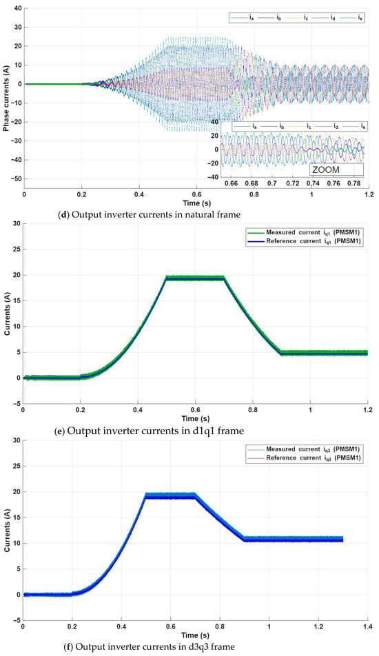
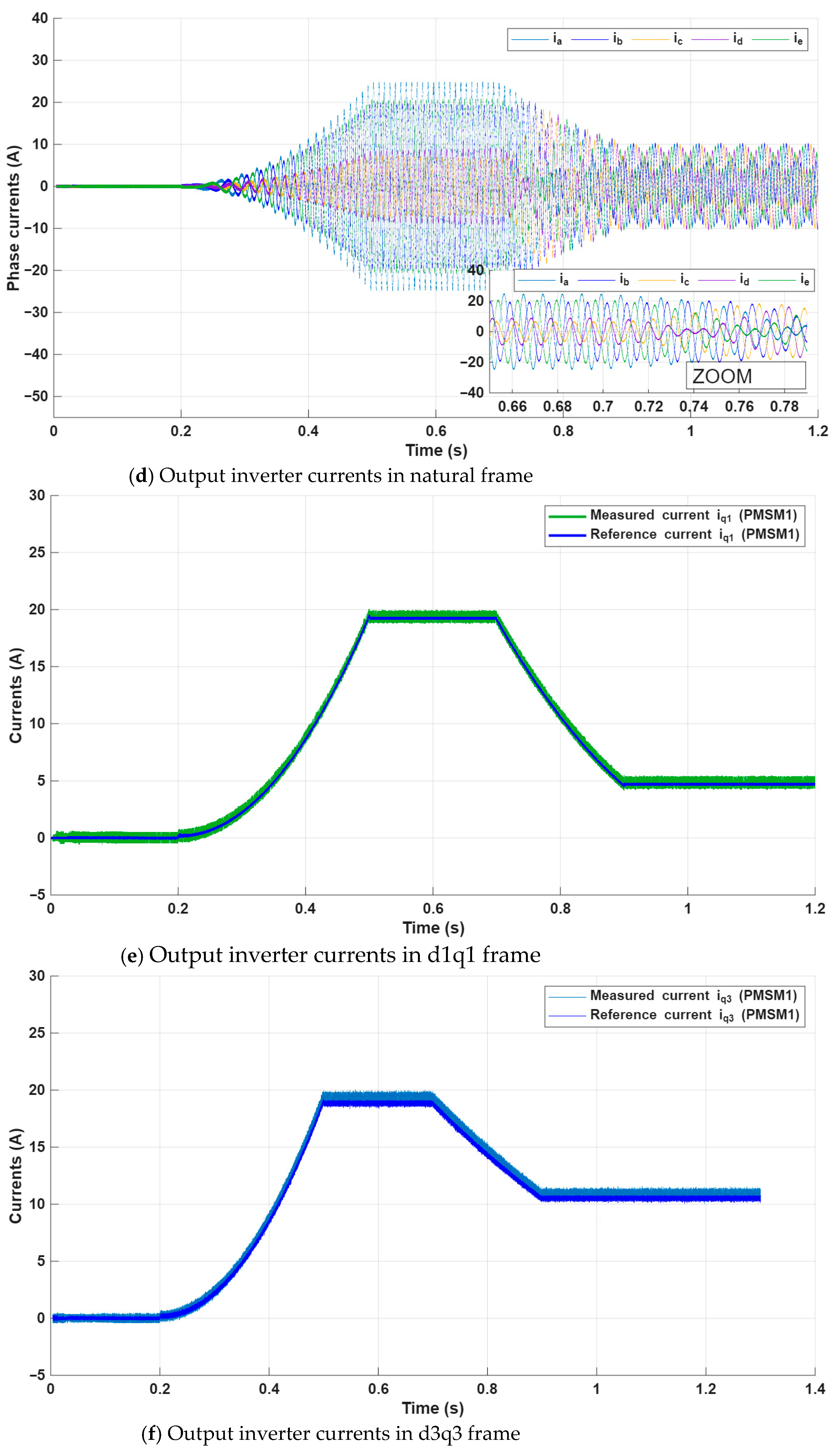
Figure 15.
Time-domain waveforms of the motor’s speeds, torques and currents for a backstepping control strategy.
In Figure 15, it is observed that the torques of both PMSMs follow a nonlinear variation law during the acceleration phase, which is in accordance with the nonlinear characteristics of the ship propulsion load. This nonlinear torque evolution persists until the motor speeds reach their steady-state values (equal to 1000 rpm for both machines).
Once the speeds become constant, the torques stabilize accordingly, reflecting the balance between the load demand and the motor output torque. It is observed again that the backstepping control strategy ensures accurate tracking of the reference speed trajectories for both machines, despite the nonlinear load dynamics and the transient operating conditions.
The smooth speed responses and the absence of significant tracking errors further confirm the effectiveness of the proposed control approach.
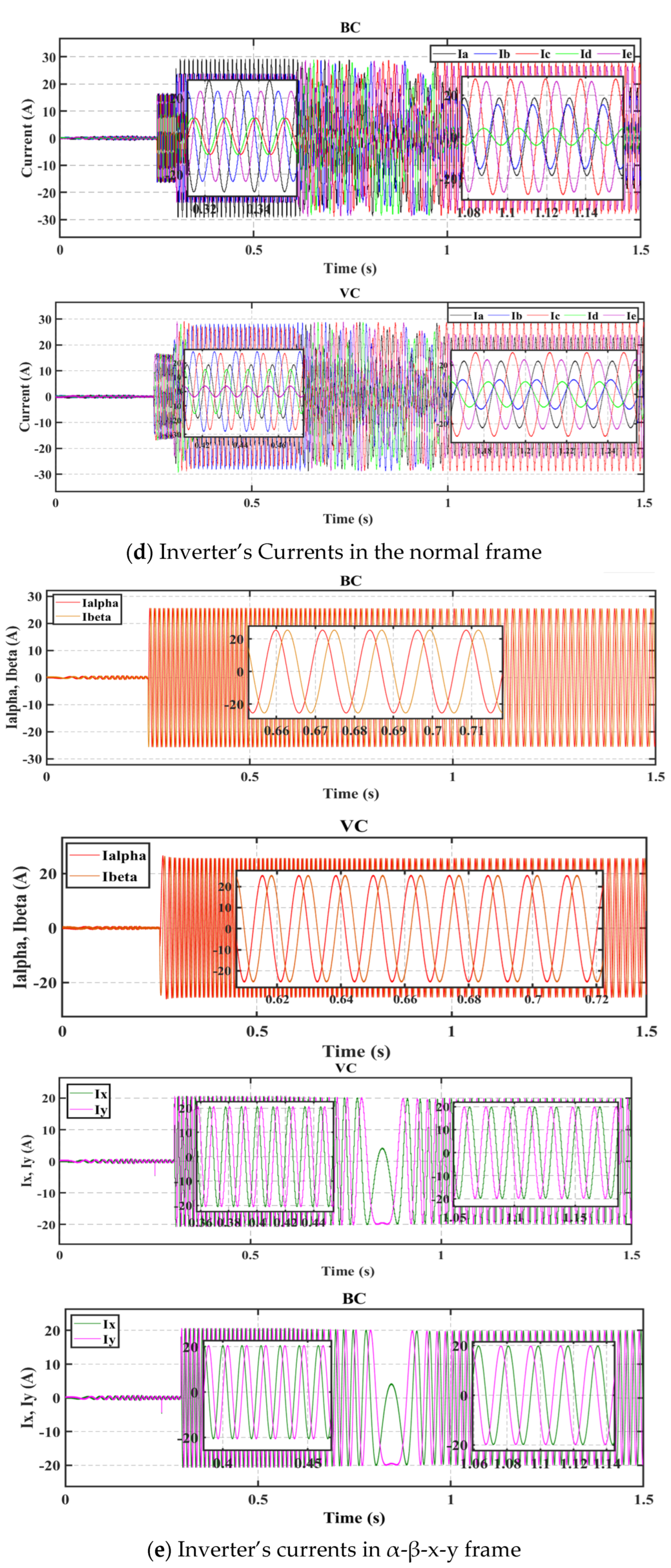
The system under study consists of two five-phase PMSMs electrically connected in series. Consequently, the currents flowing in the machine winding do not have the same amplitudes, as observed in Figure 15d. In addition, the PMSM1 is controlled in the d1q1 frame while the PMSM2 is controlled in the d3q3 frame.
This decoupling is clearly reflected in the current components, where the iq1 current regulates the torque of PMSM1, while the iq3 current is responsible for the torque control of the PMSM2. The independent evolution of these current components confirms the effectiveness of the decoupled backstepping control strategy applied to each PMSM.
5. Conclusions
This study demonstrates the effectiveness of the backstepping control for two series-connected five-phase permanent magnet synchronous machines (PMSMs) for the ship propulsion system. Simulation results in MATLAB/Simulink highlight the controller’s ability to ensure stability, minimize torque ripples and maintain precise speed regulation, which is proof of the robust nonlinear capabilities of backstepping control compared to the vector control strategy. In fact, due to joule losses, the stator resistance increases with the temperature and makes the series connection of the two machines faced to HRC.
This leads to the conclusion that the series connection of dual PMSMs can ensure the continuity of the ENPS despite such faults detected in the stator windings.
Future work could explore the integration of advanced fault-diagnosis mechanisms and optimization algorithms to further enhance the performance and fault tolerance in practical maritime environments. A comparison with other advanced control methods will be addressed in future work.
Author Contributions
Conceptualization, K.B.H. and M.T.; Methodology, K.B.H., M.T. and R.T.; Software, K.B.H. and M.T.; Validation, M.T. and R.T.; Formal analysis, M.T.; Investigation, K.B.H., M.T. and R.T.; Resources, M.T.; Data curation, M.T.; Writing—original draft, K.B.H., M.T. and R.T.; Writing—review & editing, K.B.H., M.T. and R.T.; Visualization, M.T.; Supervision, M.T., R.T. and R.A.; Project administration, M.T.; Funding acquisition, M.T. All authors have read and agreed to the published version of the manuscript.
Funding
This research received no external funding.
Data Availability Statement
The original contributions presented in this study are included in the article. Further inquiries can be directed to the corresponding author.
Conflicts of Interest
The authors declare no conflict of interest.
References
- Skjong, E.; Volden, R.; Rodskar, E.; Molinas, M.; Johansen, T.A.; Cunningham, J. Past, Present and Future Challenges of the Marine Vessel’s Electrical Power System. IEEE Trans. Transp. Electrif. 2016, 2, 522–537. [Google Scholar] [CrossRef] [Scilit]
- Moraes, T.D.S.; Nguyen, N.K.; Semail, E.; Meinguet, F.; Guerin, M. Dual-multiphase motor drives for fault-tolerant applications: Power electronic structures and control strategies. IEEE Trans. Power Electron. 2018, 33, 572–580. [Google Scholar] [CrossRef] [Scilit]
- Moraes, T.J.d.S.; Nguyen, N.K.; Meinguet, F.; Semail, E. Fault tolerant dual-motor drives: Sizing of power electronic. In Proceedings of the 2015 17th European Conference on Power Electronics and Applications (EPE’15 ECCE-Europe), Geneva, Switzerland, 8–10 September 2015; pp. 1–10. [Google Scholar] [CrossRef] [Scilit]
- Moraes, T.J.d.S.; Trabelsi, M.; Nguyen, N.K.; Semail, E.; Meinguet, F. Inverter Fault Diagnosis of an Electrical Series-Connected Two Sinusoidal Six-Phase Permanent Magnet Machines Drive. IET Electr. Power Appl. 2020, 14, 1412–1420. [Google Scholar] [CrossRef] [Scilit]
- Gataric, S. A polyphase cartesian vector approach to control of polyphase AC machines. In Proceedings of the IAS Conference on Industrial Applications of Electrical Energy, Rome, Italy, 8–12 October 2000; Volume 3, pp. 1648–1654. [Google Scholar]
- Levi, E.; Vukosavic, S.N.; Jones, M. Vector control schemes for series-connected six-phase two-motor drive systems. IEEE Proc. Electr. Power Appl. 2005, 152, 226–238. [Google Scholar] [CrossRef] [Scilit]
- Maamouri, R.; Trabelsi, M.; Boussak, M.; M’SAhli, F. Second-Order SMO-based sensorless control of IM drive: Experimental investigations of observer sensitivity and system reconfiguration in post-fault operation mode. IET Electr. Power Appl. 2021, 15, 811–823. [Google Scholar] [CrossRef] [Scilit]
- Maamouri, R.; Trabelsi, M.; Boussak, M.; M’SAhli, F. A Mixed Model-Based and Signal-Based Approach for Open-Switches Fault Diagnostic in Sensorless Speed Vector Controlled Induction Motor Drive using Sliding Mode Observer. IET Power Electron. 2019, 12, 1149–1159. [Google Scholar] [CrossRef] [Scilit]
- Toumi, S.; Elbouchikhi, E.; Amirat, Y.; Trabelsi, M.; Benbouzid, M.; Mimouni, M.F. Marine Current Turbine System Post-Fault Behavior under an Open Circuit Fault. Adv. Electr. Electron. Eng. 2018, 16, 279–287. [Google Scholar] [CrossRef] [Scilit]
- Wang, W.; Cheng, M.; Zhang, B.; Zhu, Y.; Ding, S. A fault-tolerant permanent-magnet traction module for subway applications. IEEE Trans. Power Electron. 2014, 29, 1646–1658. [Google Scholar] [CrossRef] [Scilit]
- Zhou, Y.; Chen, G. Predictive DTC strategy with fault-tolerant function for six-phase and three-phase PMSM series-connected drive system. IEEE Trans. Ind. Electron. 2018, 65, 9101–9112. [Google Scholar] [CrossRef] [Scilit]
- Hosseyni, A.; Trabelsi, R.; Mimouni, M.F.; Iqbal, A.; Alammari, R. Sensorless sliding mode observer for a FP permanent magnet synchronous motor drive. ISA Trans. 2015, 58, 462–473. [Google Scholar] [CrossRef] [Scilit]
- Zhang, X.; Sun, L.; Zhao, K.; Sun, L. Nonlinear speed control for PMSM system using sliding-mode control and disturbance compensation techniques. IEEE Trans. Power Electron. 2012, 28, 1358–1365. [Google Scholar] [CrossRef] [Scilit]
- Chaobo, C.; Ye, S.; Youmin, Z.; Jiaqiang, T.; Song, G.; Baohua, L. Adaptive fault-tolerant control of five-phase permanent magnet synchronous motor current using chaotic-particle swarm optimization. Front. Energy Res. 2022, 10, 994629. [Google Scholar]
- Li, L.-B.; Sun, L.-L.; Zhang, S.-Z.; Yang, Q.-Q. Speed tracking and synchronization of multiple motors using coupling control and adaptive sliding mode control. ISA Trans. 2015, 58, 635–649. [Google Scholar] [CrossRef] [Scilit]
- Swaroop, D.; Hedrick, J.K.; Yip, P.P.; Gerdes, J.C. Dynamic surface control for a class of nonlinear systems. IEEE Trans. Autom. Control 2000, 45, 1893–1899. [Google Scholar] [CrossRef] [Scilit]
- Ismail, R.M.T.R.; That, N.D.; Ha, Q.P. Adaptive fuzzy sliding mode control for uncertain nonlinear underactuated mechanical systems. In Proceedings of the 2013 International Conference on Control, Automation and Information Sciences, Nha Trang, Vietnam, 25–28 November 2013; pp. 212–217. [Google Scholar]
- Liang, D.; Li, J.; Qu, R.; Kong, W. Adaptive second-order sliding-mode observer for PMSM sensorless control considering VSI nonlinearity. IEEE Trans. Power Electron. 2018, 33, 8994–9004. [Google Scholar] [CrossRef] [Scilit]
- Chalanga, A.; Kamal, S.; Fridman, L.M.; Bandyopadhyay, B.; Moreno, J.A. Implementation of super-twisting control: Super twisting and higher order sliding mode observer-based approaches. IEEE Trans. Ind. Electron. 2016, 63, 3677–3685. [Google Scholar] [CrossRef] [Scilit]
- Lin, S.F.J.; Hung, Y.C.; Tsai, M.T. Fault-Tolerant Control for Six-Phase PMSM Drive System via Intelligent Complementary Sliding Mode Control Using TSKFNN-AMF. IEEE Trans. Ind. Electron. 2013, 60, 5747–5762. [Google Scholar] [CrossRef] [Scilit]
- Chen, S.; Luo, Y.; Pi, Y.G. PMSM Sensorless Control with Separate Control Strategies and Smooth Switch from Low Speed to High Speed. ISA Trans. 2015, 58, 650–658. [Google Scholar] [CrossRef] [Scilit]
- Mahmoudi, M.O.; Madani, N.; Benkhoris, M.F.; Boudjema, F. Cascade sliding mode control of field-oriented induction machine drive. Eur. Phys. J. Appl. Phys. 2007, 7, 217–225. [Google Scholar] [CrossRef] [Scilit]
- Abjadi, N.R. Sliding-mode control of a six-phase series/parallel connected two induction motors drive. ISA Trans. 2014, 53, 1847–1856. [Google Scholar] [CrossRef] [Scilit] [PubMed]
- Rastegar Fatemi, S.M.J.; Abjadi, N.R.; Soltani, J.; Abazari, S. Speed sensorless control of a six-phase induction motor drive using backstepping control. IET Power Electron. 2014, 7, 114–123. [Google Scholar] [CrossRef] [Scilit]
- Karim—Meroufel, M.A.F.M.; Abdelber, A.B. Input output linearization and sliding mode control of a permanent magnet synchronous machine fed by a three levels inverter. J. Electr. Eng. 2006, 57, 205–210. [Google Scholar]
- Vemagiri, T.; Savarapu, S. Fuzzy logic based sensorless control of five phase IPMSM drives through HF-SVI into third harmonic space. In Proceedings of the 2021 IEEE 2nd International Conference on Applied Electromagnetics, Signal Processing and Communication (AESPC), Bhubaneswar, India, 26–28 November 2021; IEEE: Piscataway, NJ, USA, 2021. [Google Scholar]
- Ammar, A.; Bourek, A.; Benakcha, A. Nonlinear SVM-DTC for induction motor drive using input-output feedback linearization and high order sliding mode control. ISA Trans. 2017, 67, 428–442. [Google Scholar] [CrossRef] [Scilit] [PubMed]
- Choux, M.; Karimi, H.R.; Hovland, G.; Hansen, M.R.; Ottestad, M.; Blanke, M. Robust adaptive backstepping control design for a nonlinear hydraulic-mechanical system. In Proceedings of the 48h IEEE Conference on Decision and Control (CDC) held jointly with 2009 28th Chinese Control Conference, Shanghai, China, 15–18 December 2009; IEEE: Piscataway, NJ, USA, 2009; pp. 2460–2467. [Google Scholar]
- Lin, F.J.; Chang, C.K.; Huang, P.K. FPGA-based adaptive backstepping sliding-mode control for linear induction motor drive. IEEE Trans. Power Electron. 2007, 22, 1222–1231. [Google Scholar] [CrossRef] [Scilit]
- Trabelsi, R.; Khedher, A.; Mimouni, M.F.; M’Sahli, F. Backstepping control for an induction motor using an adaptive sliding rotor-flux observer. Electr. Power Syst. Res. 2012, 93, 1–15. [Google Scholar] [CrossRef] [Scilit]
- Hosseyni, A.; Trabelsi, R.; Mimouni, M.F.; Iqbal, A. Backstepping Control for a Five-Phase Permanent Magnet Synchronous Motor Drive. Int. J. Power Electron. Drive Syst. (IJPEDS) 2015, 6, 842–852. [Google Scholar] [CrossRef] [Scilit]
- Echeikh, H.; Trabelsi, R.; Iqbal, A.; Bianchi, N.; Mimouni, M.F. Comparative study between the rotor flux-oriented control and non-linear backstepping control of a five-phase induction motor drive an experimental validation. IET Power Electron. 2016, 9, 2510–2521. [Google Scholar] [CrossRef] [Scilit]
- Iqbal, M.A.; Memon, A.Y. Robust Backstepping Sensorless Speed Control of PMSM Using Cascaded Sliding Mode and High Gain Observers. In Proceedings of the International Symposium on Recent Advances in Electrical Engineering (RAEE), Islamabad, Pakistan, 28–29 August 2019. [Google Scholar]
- Bekkour, E.-H.; Sakhri, Z.; Mahfoud, S.; Bossoufi, B.; Merzouk, S.; Mosaad, M.I.; Hussien, S.A. An advanced sensorless control strategy using PS-EKF-based Integral Backstepping Controller for PMSM: Experimental validation using dSPACE DS1104. Sci. Afr. 2025, 29, e02951. [Google Scholar] [CrossRef] [Scilit]
- Atallah, M.; Benmahdjoub, M.A.; Salhi, I.; Mezouar, A.; Saidi, Y.; Gaillard, A. Efficient nonlinear integral backstepping control for doubly fed induction generators-based wind farm under unbalanced electrical grid voltage. Int. J. Electr. Power Energy Syst. 2025, 172, 111141. [Google Scholar] [CrossRef] [Scilit]
- Arish, N.; Kamper, M.J.; Wang, R.-J. Advancements in Electrical Marine Propulsion Technologies: A Comprehensive Overview. S. Afr. Inst. Electr. Eng. 2025, 116., 14–29. [Google Scholar] [CrossRef] [Scilit]
- Zhao, H.; Gong, J.; Tan, F.; Semail, E.; Nguyen, N.K.; Bracikowski, N.; Gillon, F. Design, Analysis and Control of a Low Speed and High Torque Five-phase External Rotor Permanent Magnet Synchronous Machine for Direct Drive Application. IEEE Trans. Energy Convers. 2024, 40, 1110–1124. [Google Scholar] [CrossRef] [Scilit]
- Gupta, S.K.; Singh, O.; Khan, M.A.; Kushwaha, A.K. A review on developments of polyphase machines. J. Inf. Optim. Sci. 2020, 41, 327–343. [Google Scholar] [CrossRef] [Scilit]
- Nekkaz, M.; Djahbar, A.; Taleb, R. Modeling and control of two five-phase induction machines connected in series powered by matrix converter. Int. J. Power Electron. Drive Syst. (IJPEDS) 2021, 12, 685–694. [Google Scholar] [CrossRef] [Scilit]
- Xu, X.; Hang, J.; Cao, K.; Ding, S.; Wang, W. Unified Open Phase Fault Diagnosis of Five-Phase PMSM System in Normal Operation and Fault-Tolerant Operation Modes. IEEE Trans. Transp. Electrif. 2025, 11, 12063–12075. [Google Scholar] [CrossRef] [Scilit]
- Fall, O.; Charpentier, J.F.; Nguyen, N.-K.; Letellier, P. Maximum torque per ampere control strategy of a 5-phase PM generator in healthy and faulty modes for tidal marine turbine application. In Proceedings of the 2014 International Power Electronics and Application Conference and Exposition, Shanghai, China, 5–8 November 2014; pp. 468–473. [Google Scholar] [CrossRef] [Scilit]
- Fall, O.; Nguyen, N.K.; Charpentier, J.F.; Letellier, P.; Semail, E.; Kestelyn, X. Variable speed control of a 5-phase permanent magnet synchronous generator including voltage and current limits in healthy and open-circuited modes. Electr. Power Syst. Res. 2016, 140, 507–516. [Google Scholar] [CrossRef] [Scilit]
- Sardar, M.U.; Vaimann, T.; Kütt, L.; Kallaste, A.; Asad, B.; Akbar, S.; Kudelina, K. Inverter-Fed Motor Drive System: A Systematic Analysis of Condition Monitoring and Practical Diagnostic Techniques. Energies 2023, 16, 5628. [Google Scholar] [CrossRef] [Scilit]
- Benyahia, N.; Badji, A.; Aissou, S.; Charpentier, J.-F.; Becker, F.; Scuiller, F.; Bousbaine, A.; Ould-Abdeslam, D. Enhanced real-time emulator for naval propulsion: Application to an electric boat powered by a PEM fuel cell. Energy Convers. Manag. X 2025, 27, 101077. [Google Scholar] [CrossRef] [Scilit]
- Trabelsi, M.; Semail, E. Virtual current vector-based method for inverter open-switch and open-phase fault diagnosis in multiphase permanent magnet synchronous motor drives. IET Electr. Power Appl. 2021, 16, 1476–1491. [Google Scholar] [CrossRef] [Scilit]
- Kommuri, S.K.; Park, Y.; Lee, S.B. High-Resistance Fault Control in Permanent Magnet Synchronous Motors. IEEE/ASME Trans. Mechatron. 2020, 25, 271–281. [Google Scholar] [CrossRef] [Scilit]
- Jia, Z.; Song, W.; Ma, C.; Lu, T.; Huang, W. A Generalized Current Residual-Based Diagnosis and Classification Method for Interturn Fault and High-Resistance Connection Fault in Model Predictive Controlled PMSMs. IEEE Trans. Power Electron. 2025, 40, 7239–7250. [Google Scholar] [CrossRef] [Scilit]
- Cao, W.; Li, H.; Hu, C.; Wang, H.; Huang, R.; Lu, S.; Huang, X. Diagnosis of High-Resistance Connection Faults in PMSMs Based on GMR and Deep Learning. IEEE Trans. Ind. Electron. 2024, 71, 7915–7923. [Google Scholar] [CrossRef] [Scilit]
- Senhaji, A.; Abdelouhab, M.; Attar, A.; Bouchnaif, J. Backstepping control of a permanent magnet synchronous motor. Mater. Today Proc. 2023, 72, 3730–3737. [Google Scholar] [CrossRef] [Scilit]
- Mekri, F.; Charpentier, J.-F.; Semail, E. An efficient control of a series connected two-synchronous motor 5-phase with non-sinusoidal EMF supplied by a single 5-leg VSI: Experimental and theoretical investigations. Electr. Power Syst. Res. 2012, 92, 11–19. [Google Scholar] [CrossRef] [Scilit]
- Senhaji, A.; Amri, L.; Ouaanabi, A.; Bouchnaif JHajji, B.; Gagliano, A.; Mellit, A.; Rabhi, A.; Calì, M. (Eds.) Adaptive Backstepping Control for PMSM. In Proceedings of the 4th International Conference on Electronic Engineering and Renewable Energy Systems (ICEERE) 2024; Springer: Singapore, 2025; Volume 1306. [Google Scholar]
- Zhang, Y.; Yan, Q.; Huang, N.; Wu, Z.; Gong, H.; Du, G. Fuzzy Approximation-Based Backstepping Control of Permanent Magnet Synchronous Motor. J. Electr. Eng. Technol. 2023, 18, 2115–2126. [Google Scholar] [CrossRef] [Scilit]

Disclaimer/Publisher’s Note: The statements, opinions and data contained in all publications are solely those of the individual author(s) and contributor(s) and not of MDPI and/or the editor(s). MDPI and/or the editor(s) disclaim responsibility for any injury to people or property resulting from any ideas, methods, instructions or products referred to in the content. |
© 2026 by the authors. Licensee MDPI, Basel, Switzerland. This article is an open access article distributed under the terms and conditions of the Creative Commons Attribution (CC BY) license.