Abstract
Bolted connections are critical in deep-sea engineering, yet classical theories (such as VDI 2230) implicitly assume atmospheric pressure conditions, neglecting the volume contraction of components due to hydrostatic pressure. This fundamental flaw hinders accurate prediction of preload retention—especially when bolts and clamped components exhibit differential compressibility (a common scenario in practical applications). To bridge this scientific gap, this paper establishes the first analytical model for bolt preload under pressure-induced volumetric contraction based on deformation coordination relations. The derived closed-form expressions explicitly quantify residual preload as a function of deep-sea ambient pressure, component bulk modulus, and geometric parameters. Model predictions closely match finite element calculations, showing that stainless steel bolts clamping aluminum alloys under 110 MPa pressure can experience up to a 40% preload reduction. This theoretical framework extends classical bolt connection mechanics to high-pressure environments, providing a scientific basis for optimizing deep-sea connection designs through material matching and dimensional control to effectively mitigate pressure-induced preload loss.
1. Introduction
With high reliability, easy to install and dismantle, low cost, easy to test and maintain, standardization, and many other advantages [1,2,3,4,5], bolted joints are widely used in the field of ocean engineering, such as submarine oil and gas pipelines [6], offshore wind turbines [7], offshore platform [8], and various types of underwater operating equipment [9,10,11,12,13]. Therefore, whether the bolt can provide a long-term, stable, and reliable service in the ocean environment is a concern of many scholars.
For submarine oil and gas pipelines, the consequence of structural failure can be particularly catastrophic. Risk assessment studies reveal that pipeline instability under hydrodynamic forces poses significant threats, with failure probabilities being directly linked to environmental loads and operational conditions [14]. In the Sakarya Gas Project in the Black Sea, a 170 km pipeline at a 2200 m water depth is designed to transport natural gas from a field with reserves of 540 billion cubic meters, where any minor joint failures could trigger severe environmental disasters and economic losses [14]. Such system-level risks underscore the critical importance of every connection component, especially bolted joints that maintain structural integrity under extreme subsea conditions.
These risks are not limited to subsea pipeline systems. All deep-sea equipment, such as manned submersibles, remotely operated vehicles, and seabed mining vehicles, relies on critical bolted joints that must maintain integrity under extreme deep-sea conditions. Figure 1 shows the Kunlong 500 seabed polymetallic nodule mining vehicle we participated in developing. As seen in the figure, numerous bolted connections are employed throughout the vehicle—whether in sealing the hatch of the electronics compartment housing the control system, linking critical actuators to the main body, or connecting pipes to pumps and valves within the hydraulic power system. Failure at any single bolted joint could cause the polymetallic nodule mining vehicle to malfunction, potentially disrupting the entire seabed mining operation.
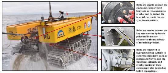
Figure 1.
Boltson a seabed polymetallic nodule mining vehicle.
In bolted joints, a reduced preload force, or even joint failure, can lead to connection loosening under external loads or vibrations. This may cause further deformation of the overall structure [15], or, in severe cases, complete separation of the clamped parts [16]. In addition, insufficient bolt preload force may cause leakage at sealing connections [17]. In critical subsea operations, such failures can escalate into emergency situations including uncontrolled oil and gas leaks, loss of remotely operated vehicles, or platform shutdown, resulting in substantial environmental and economic consequences. It is worth noting that in underwater environments, hydrodynamic loads further exacerbate the risk of bolt loosening.
Many examples of bolt failures have been reported. Escobar et al. [18] presented a failure analysis where the use of non-conforming carbon steel bolts in a corrosive submersible pump environment led to pitting-induced stress corrosion cracking and subsequent structural failure. Lindley et al. [19] reported the catastrophic failure of a subsea safety-critical bolt in the Gulf of Mexico, where synchrotron X-ray tomography and scanning electron microscopy identified chloride stress corrosion cracking and hydrogen embrittlement as primary failure mechanisms, both exacerbated by elongated MnS inclusions. Qin et al. [8] reported a fractured bolt failure at a pressure gauge in a fuel gas system on an offshore platform. Ivanega and Szczepanek [10] reported the leak failure of the compensator in the Schilling Titan 4 underwater hydraulic manipulator caused by three broken bolts. Yang et al. [13] reported the fracture failure of bolts in the buoyancy regulator of an underwater glider due to overload. Yu et al. [20] reported the failure of oil/gas platforms in the Bohai Sea, in which the reduction in flange preload force caused by loosened bolts was the main cause of pipeline flange failure. During the 1000 m sea trials, the tether management system of the ROSUB 6000 ROV experienced a bolt fracture, with the point of fracture being located at the weakest point of contact between the thread and the nut [21].
In order to enhance the service reliability of bolted joints in the offshore or subsea, a large number of scholars have conducted in-depth research on their performance. For bolted joints on floating offshore wind turbine towers, Yang and Qin [7] investigates the appropriate target safety level and the corresponding load safety factor, while Lin et al. [22] investigates fatigue due to the preload loss caused by ambient temperature creep. Tao et al. [23] enhances the annual power generation of offshore wind farm by 1.818% through yaw optimization control, but the corresponding cost is the reduction in the fatigue life of bolted joints on offshore wind turbine towers by about 3–9 years. Based on a combined analytical and finite element modeling method, Wang et al. [24] investigate the effects of conveying medium temperature on the loads and the variations in the bolts used in the connecting flanges of submarine pipelines. In evaluating and analyzing the sealing reliability of underwater connectors, both Liu et al. [6] and Hao et al. [25] focused on the transfer relationship from the preload force of the bolted joint to the contact force of the seal component. Ripsch and Henkel [26] examined the effect of water on tightening, bolt preload and slip coefficients using specialized test equipment and identified self-loosening and bolt overload as potential risks for the underwater installation of bolted joints. The study by Murdy et al. [27] provided crucial experimental evidence that hygrothermal aging in seawater significantly compromises the static and fatigue performance of thick composite T-bolt connections, emphasizing the need to account for environmental degradation in the design of marine renewable-energy structures. In a study on marine sandwich composite bolted connections, Qiu et al. [28] proposed an improved fatigue life prediction method that accounts for both fiber panel and foam core degradation, and validated its accuracy through fatigue tests and progressive damage simulations using ABAQUS UMAT. Mehta et al. [29] experimentally determined that optimized thread engagement (1D) and coating-specific nut factors can enhance the reliability and cost-efficiency of subsea bolted connections, providing key parameters absent in current design standards. The study by Xie et al. [30] provides a fatigue-life-based framework for optimizing bolt preload in subsea connectors subjected to vortex-induced vibration, highlighting the superiority of the hydraulic tensioning method in mitigating the detrimental effects of preload scatter.
There are also many scholars devoted to reliability assessments and loosening detection in underwater bolts. Based on machine learning, He et al. [31] propose a method to detect the loosening of underwater bolted joints by changes in sound frequency characteristics caused by percussion. The method developed by Wang et al. [32] also utilizes the acoustic signal characteristics of percussion, but their method is based on the least square support vector machine. Wang et al. [33] developed an underwater multi-bolt loosening recognition method using entropy-enhanced active perception and integrated learning. Jiang et al. [34] proposed a touch-based active sensing method for piezoelectric ceramic sensors to examine subsea bolted connections. To address challenges in real-time bolt loosening detection, Gao et al. [35] enhanced the YOLOv8 model by integrating a MobileViT backbone, a large separable kernel attention (LSKA) module, and a dedicated small-target detection layer, significantly improving performance in complex environments.
Existing studies have identified underwater bolt failures as a material–environment–mechanics coupling problem. Material non-compliance (e.g., substituting Monel K-500 with carbon steel or using low-chromium stainless steel) precipitates pitting and stress corrosion cracking (SCC) in chloride/sulfide environments [8,18]. Advanced forensics confirm SCC initiates at metallurgical defects (e.g., MnS inclusions) and propagates under synergistic hydrogen and chloride attack [19]. Mechanical preload significantly affects corrosion behavior—higher torque increases corrosion rates by over four times, while cathodic protection efficacy diminishes with temperature increases, potentially inducing hydrogen embrittlement [36,37].
However, these studies primarily focus on corrosion and hydrogen embrittlement governed by chemical/electrochemical coupling mechanisms, based on material constitutive behavior under atmospheric pressure. The direct influence of high-pressure environments on the mechanical performance of bolted connections has not been adequately addressed. The existing literature generally overlooks the volume contraction effect induced by deep-sea hydrostatic pressure and its potential impact on preload, which is particularly critical for equipment undergoing frequent depth variations or long-term residency at 110 MPa pressure environments.
1.1. Scientific Deficit in Bolted Joint Theory
Despite extensive research on corrosion-related failures, the fundamental mechanics of preload retention under high hydrostatic pressure remain theoretically unaddressed. Classical bolted joint theories (VDI 2230 [5]) are derived under the implicit assumption of atmospheric pressure, where the bulk deformation of embedded components is negligible. This leads to a critical scientific gap: no analytical framework exists to predict how differential compressibility between bolts and clamped parts (e.g., steel vs. aluminum) translates into quantifiable preload loss. The absence of pressure-dependent compliance terms in existing models means that preload variation in deep-sea equipment—where pressure cycles between 0 and 110 MPa—cannot be accurately predicted, hindering both lifecycle assessment and failure prevention.
1.2. Engineering Consequences and Practical Risks
This theoretical deficit creates three critical problems in deep-sea equipment: (1) seal failure–40% preload loss (shown in this study) can cause flanges to leak, leading to water ingress and system failure; (2) structural loosening and wear-reduced clamping force allows bolted parts to slip and rub, causing progressive damage under ocean currents and vibrations; (3) performance instability–varying preload changes joint stiffness, affecting the precision and response of underwater vehicles and manipulators. Existing design guidelines fail to account for preload loss in deep-sea high-pressure environments, forcing engineers into a dilemma: either overdesign (increasing cost/weight) or accept unknown risks. The preload loss mechanism identified in this study, combined with corrosion effects, fully reveals the complete picture of deep-sea bolt failure.
1.3. Goals and Objectives of This Study
This paper aims to address this scientific deficit by developing the first analytical model for pressure-dependent preload variation in deep-sea bolted joints. The specific objectives are: (1) Theoretical Derivation: establish an explicit expression for residual preload that incorporates differential compressibility of bolt and clamped materials under hydrostatic pressure; (2) Model Validation: develop a finite element model to verify the analytical predictions across realistic pressure ranges (0–110 MPa); (3) Design Optimization: provide practical guidelines for material selection and dimensioning to mitigate pressure-induced preload loss. By bridging the gap between fundamental mechanics and deep-sea engineering practice, this work provides both a scientific framework and actionable design recommendations for enhancing reliability in extreme subsea environments.
1.4. Methodological Framework
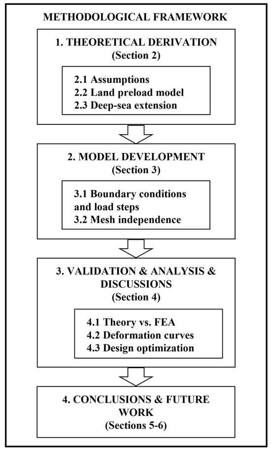
The methodological framework of this study is illustrated in Figure 2. The research follows a sequential workflow: (1) theoretical derivation of residual preload expressions (Section 2); (2) development of a finite element model (Section 3); (3) validation, parametric analysis, and design discussions (Section 4); (4) conclusions and future work (Section 5 and Section 6).
2. Theoretical Analysis
2.1. Assumptions
The theoretical analysis focuses on the coordination of axial deformation between bolts and clamped components caused by deep-sea ambient pressure. To highlight the dominant influence of volumetric contraction on preload force variation, the following assumptions are adopted:
- 1.
- The effect of friction at the threaded section is negligible: The analysis assumes the nut remains stationary under deep-sea ambient pressure, with axial deformation being the primary deformation mode. Consequently, the friction coefficient at the thread contact surfaces is excluded from the derivation. This assumption is justified because, unlike dynamic loads or vibration-induced loosening, deep-sea ambient pressure—as a static, isotropic compressive load—does not generate relative motion or torque at the thread contact surfaces.
- 2.
- Linear elastic, isotropic material behavior: Both the bolt and the clamped material are assumed to remain within their elastic limits and exhibit isotropic compression under pressure.
These explicitly stated assumptions define the scope of the current analysis, whose core objective is to investigate pressure-induced volumetric effects rather than traditional friction-driven self-loosening mechanisms.
2.2. Preloading of Bolts on Land
The clamped parts are usually of various shapes, with the most common being flange shapes and the simplest being cylindrical. It is difficult to directly calculate the elastic compression of non-cylindrical clamped parts. However, it can be approximated as a cylindrical part according to certain rules [5]. Therefore, the cylindrical clamped parts shown in Figure 3 are analyzed and studied in this study.
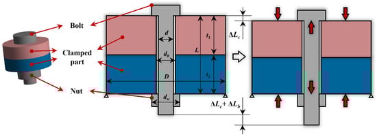
Figure 3.
Pre-tensioning of bolts for land-based conditions.
Figure 3 also clearly shows the preloading of a bolt joint in land working conditions. The bolt with diameter d is stretched by under the preload force , while the two clamped parts with outer diameter D and total thickness L are compressed by . The pre-tensioned connection for land-based conditions can also be depicted in Figure 4. The red line indicates that the bolt is elongated by the preload force , while the blue line indicates that the clamped parts are compressed by .
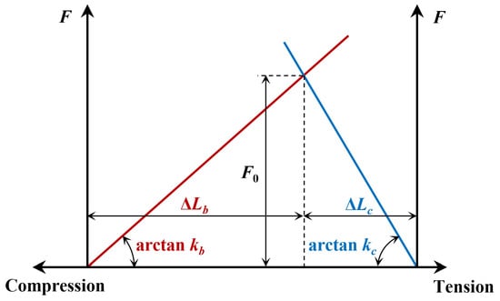
Figure 4.
Force-deformation curves for land conditions (red line is for the bolt; blue line is for the clamped parts).
Taking the stiffness of the bolt and the two clamped parts as and , respectively, we have
The stiffness of a cylindrical bolt can be calculated by the following equation:
where is the elastic modulus of the bolt material.
The stiffness of the clamped parts is much more complex. The clamped parts will have a conical deformation region under the preload force [5]. Whether the clamped parts can fully accommodate this cone of deformation and whether the clamped parts are made of the same material has an effect on the stiffness. The half cone angle can be calculated by the following equation [5]:
where is the diameter of the contact area of the bolt and nut, and D is the outer diameter.
Among the many equations for calculating the stiffness of the clamped parts [38,39,40,41,42], the one proposed by Nassar and Abboud [38] was chosen in this study because it agrees well with both finite element calculations and experimental tests. When the two clamped parts are of the same material and the outer diameter D satisfies , is
where and are the modulus of elasticity of the clamped part and the diameter of the hole, respectively.
When the two clamped parts are of the same material but D satisfies , the is
When the modulus of elasticity of the two clamped members are and , the thicknesses are and , respectively, and D satisfies , the is
And when the modulus of elasticity of the two clamped members are and , the thicknesses are and , respectively, and D satisfies , the is
2.3. Residual Preload Force for Deep-Sea Conditions
Under the effect of the ubiquitous and depth-increasing deep-sea ambient pressure , both the bolt and the clamped parts undergo volume contraction. Therefore, as shown on the left side of Figure 5, the axial lengths of the bolt and the clamped member in the connection region shrink by and , respectively. and can be calculated as
where is the deep-sea ambient pressure, is the bulk modulus of the bolt material, and and are the bulk moduli of the two clamped parts. They satisfy the following relationship with the corresponding modulus of elasticity (, and ) and Poisson’s ratio (, and ):
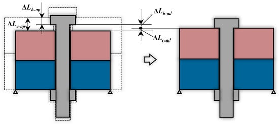
Figure 5.
Deformation and deformation coordination of bolted assemblies in deep-sea environments.
Usually, the bulk modulus of the bolt material is greater than or equal to the bulk modulus of the clamped parts, which means that is less than . The difference between and means that the clamped part compressed by the preload force will be adjusted to elongate a certain amount () in the axial direction, while the bolt tensioned by will be adjusted to contract a certain amount (), as shown in Figure 5. From the deformation coordination relation, the following relation can be obtained:
Due to the readjustment of the deformation, the preload force is changed. The changed part satisfies the following relationship:
Therefore, the change in preload force due to the deformation caused by the deep-sea ambient pressure is
Ultimately, the residual preload force in the deep-sea environment is
3. Finite Element Model
3.1. Boundary Conditions and Load Steps
In this study, finite element simulation results are used to verify the correctness of the theoretical analysis in the previous section. The software platform used is ANSYS 2020 R1. Due to the axisymmetric nature of the geometric features, a tenth model is used in the study to save computational resources, as shown in Figure 6. Table 1 lists the values of all the initial geometric parameters in Figure 3. There are four contact pairs in Figure 6, and their settings are shown in Table 2. Given Assumption 1 in Section 2.1, the finite element model employs a bonded contact at the bolt–nut thread interface(i.e., Contact pair 4 in Table 2), which effectively enforces displacement continuity without modeling detailed thread geometry. This simplification is appropriate for capturing the bulk compression effect under static pressure. The bolts and nuts are made of stainless steel, while the clamped parts are made of aluminum alloy. The material parameters of each part are shown in Table 3.
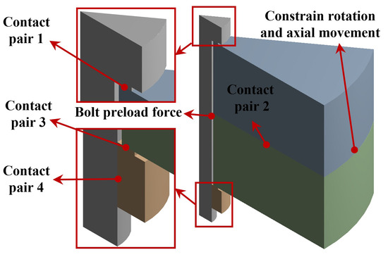
Figure 6.
Boundary conditions.

Table 1.
Geometric dimensions.
Table 2.
Contact settings.
Table 3.
Material parameters.
The load is applied in two steps. The first step is the application of bolt preload. As shown in Figure 6, a preload force of 1000 N is applied to the cylindrical surface of the bolt in the hole of the clamped parts, which corresponds to a preload force of 10,000 N applied to the whole bolt because of the one-tenth model. The second step is to apply 110 MPa of deep-sea ambient pressure to all external surfaces except the symmetry plane, which corresponds to the ambient pressure at a depth of 11,000 m (bottom of the Mariana Trench).
3.2. Mesh Independence Study
After the calculation, the axial force between each contact pair is equal to the residual preload force. The variation in the residual preload force with the number of elements for the 11,000 m deep-sea condition is shown in Figure 7. This indicates that the residual preload force decreases as the number of elements increases. The meshing chosen for this study has 131,556 elements, as shown in Figure 8. The deviation of the corresponding residual preload force is only 0.45% compared to the case of 920,416 elements, which shows that the mesh division has sufficient accuracy.
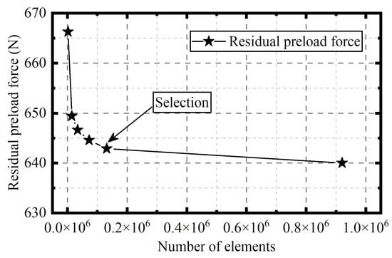
Figure 7.
The residual preload force varies with the number of elements.
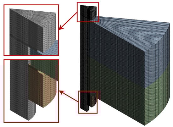
Figure 8.
Mesh.
4. Results and Discussion
This section presents the validation of the theoretical model through finite element analysis (Section 4.1), followed by a discussion of the pressure-induced deformation characteristics (Section 4.2) and derived design recommendations (Section 4.3).
To contextualize our contribution, it is important to note that existing studies on bolted joints have primarily focused on the following:
- 1.
- Friction-induced self-loosening under vibration and dynamic loads for terrestrial applications [43,44,45].
- 2.
- Corrosion fatigue and material degradation in offshore structures [8,46,47].
- 3.
- Simplified axial stiffness calculations without considering hydrostatic pressure effects [38,39,40,41,42].
The current work differs fundamentally by isolating and quantifying the pure volumetric contraction effect under deep-sea ambient pressure, which is a static, isotropic load that does not involve traditional loosening mechanisms. This provides a new analytical dimension for subsea bolted joint design that complements, rather than duplicates, previous research.
4.1. Comparison of Finite Element Calculation Results with Theoretical Analysis
The axial deformations of the contact surfaces of the two clamped parts with the bolt and the nut after applying the initial bolt preload force of 10,000 N are shown in Figure 9 and Figure 10, respectively. The stiffness of the clamped parts, calculated from the average deformation, is N/mm. The theoretical stiffness obtained with Equation (5) is 466,791 N/mm. The relative error is 6.2%.
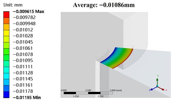
Figure 9.
Axial deformation of the bolt–contact surface of the upper clamped part.
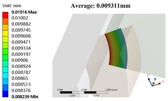
Figure 10.
Axial deformation of the nut–contact surface of the lower clamped part.
The bolt and nut are in close contact with the two clamped parts. As a result, the axial deformation of the two clamped parts causes a corresponding axial deformation of the two circumferences of the column portion of the bolt located in the hole, as shown in Figure 11. To ensure a tight connection, the ANSYS bolt preload tool calculates a pretension section adjustment, representing the net axial deformation resulting from the applied pretension load. This adjustment includes bolt elongation and compression of the clamped parts. Finite element calculations show that the adjustment is 0.05864 mm. Therefore, the elongation of the bolt itself is mm. The corresponding bolt stiffness is N/mm. The theoretical stiffness obtained from Equation (3) is 324,840 N/mm. The relative error is −2.1%.
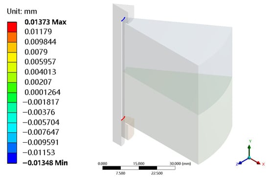
Figure 11.
Axial deformation of the upper and lower circumferences of the column portion of the bolt located in the hole.
Figure 12 illustrates the overall deformation under the deep-sea ambient pressure of 110 MPa. The spherical distribution of deformation indicates that overall shrinkage occurred, while the faulty misalignment in the deformation distribution between the clamped parts and the bolts indicates that the degree of shrinkage was not uniform. The finite element simulation results show that the residual preload force is 6428.6987 N. The theoretical value calculated according to Equation (16) is 6017.7360 N. The relative error is 6.8%. Particularly noteworthy is the fact that the preload force is reduced by a staggering 40% compared to the initial value when calculated using theoretical values.
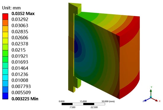
Figure 12.
Overall deformation under the deep-sea ambient pressure of 110 MPa.
Finite element calculations were also carried out for various deep-sea ambient pressures, clamped part dimensions, and materials (including titanium alloy, stainless steel, and aluminum alloy, which are commonly used in ocean engineering). The residual preload forces obtained from these simulations show good agreement with theoretical values across all cases, validating the analysis in Section 2. Detailed parametric data for all simulation cases are provided in Table A1.
4.2. Force–Deformation Curves for Deep-Sea Conditions
Due to the inconsistent deformation of the bolt and the clamped part under the deep-sea ambient pressure, the bolt is adjusted to shrink by (Equation (13)) and the clamped parts are adjusted to elongate by (Equation (14)). This means that the force–deformation curve of the bolt and its corresponding longitudinal axis (force F) should be shifted to the right by for deep-sea conditions, while that of the clamped parts should be shifted to the left by . Figure 13 shows the force–deformation curves for deep-sea conditions, adjusted on the basis of Figure 4, where the dashed lines represent land conditions.
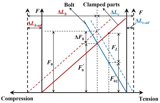
Figure 13.
Force–deformation curves for deep-sea conditions (red lines represent the bolt, blue lines represent the clamped parts, and dashed lines represent the land conditions).
Figure 13 clearly shows that under the effect of the structural deformation caused by the deep-sea ambient pressure, the preload force changes from the initial on land to the residual preload , reducing by . Some bolted connections are also subjected to tensile working loads . In this case, the bolts will be further tensioned, while the clamped parts are thus loosened, resulting in a further reduction in the residual preload force to , as shown in Figure 13. From the parallelism of the curves, it can be seen that is lower than that under the same working load for land conditions by .
4.3. Recommendations for Optimized Design of Bolted Joints in Deep-Sea Conditions
A reduction in the preload force ( ) may result in loosening of the connection under external loads or vibrations as well as further deformation of the overall structure or even complete separation of the clamped parts. In the case of seals, leaks may occur due to insufficient preload force. In addition, the amount of change in preload force, , is directly related to the deep-sea ambient pressure or the working depth. This means that bolted connections operating at variable depths are subjected to additional alternating loads, further affecting their fatigue life. Therefore, it is necessary to minimize in order to ensure the reliability of bolted joints in deep-sea conditions.
According to Equations (9) and (15), the fundamental solution is to use the same material for the bolt and the clamped part. In this case, there will be no decrease in preload force due to inconsistency in the degree of deformation of the bolt and the clamped part, i.e., is equal to 0. When the materials cannot be identical, the smaller the difference in bulk modulus, the closer the dimensional change in the bolt and the clamped part under the deep-sea ambient pressure, and the smaller the deformation that needs to be readjusted and coordinated by each part; therefore, the smaller the . If, due to structural constraints, performance requirements, and lightweighting needs, the materials can not be the same or have a similar bulk modulus, the most direct way to increase the residual preload force is to increase the initial preload force by according to Equation (15) for compensation.
In the case of bolted connections working at variable depths, compensation of the initial preload force alone is not able to reduce the alternating load amplitude, and it is then necessary to design in the dimensions of the bolt structure in order to reduce the change amount in preload force, .
When the bolts is stainless steel and both clamped parts are aluminum alloys, according to Equations (5), (6) and (15) and the initial set values in Section 3.1, how the change amount in preload force, , varies with the total thickness L or outside diameter D of the clamped parts is plotted in Figure 14. Figure 14 shows that the smaller the thickness L and the outer diameter D, the smaller is. This trend suggests that, when the clamped parts are made of the same materials, a more compact size, i.e., a lower thickness L and outer diameter D, can lead to a smaller change amount in preload force, , in deep-sea conditions. It should be noted, however, that such geometrical optimization must be balanced against the structural strength and integrity requirements of the clamped components.
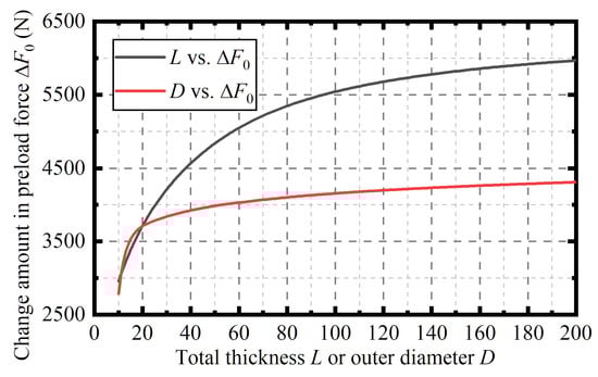
Figure 14.
The change amount in preload force, , varies with the total thickness L or outside diameter D of the clamped parts when the bolt is stainless steel and the two clamped parts are aluminum alloys.
When the bolts are stainless steel, the upper clamped part is an aluminum alloy, and the lower clamped part is a titanium alloy, according to Equations (7), (8) and (15) and the initial set values in Section 3.1, how the change amount in preload force, , varies with the thickness ratio, , is plotted in Figure 15. Figure 15 shows that the larger the thickness ratio is, the smaller is. The material of the lower clamped member corresponding to the thickness is a titanium alloy, which has a higher bulk modulus. Therefore, the trend in Figure 15 indicates that when the two clamped parts are of different materials, increasing the thickness of the clamped part with a larger bulk modulus can reduce the reduction in preload force in deep-sea conditions.
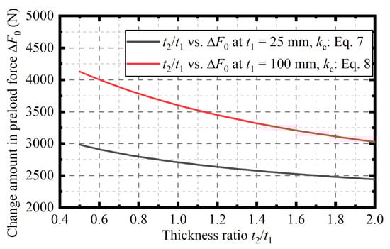
Figure 15.
The change amount in preload force, , varies with the thickness ratio, : when the bolt is stainless steel, the upper clamped part is an aluminum alloy, and the lower clamped part is a titanium alloy.
5. Conclusions
In this paper, an in-depth study on the variation in preload force in bolted joints due to deformation caused by deep-sea high ambient pressure was carried out, and the main research contents and results obtained are summarized as follows:
- 1.
- The deformation of bolts and clamped parts under the deep-sea ambient pressure is analyzed, and an explicit expression for the residual preload force of bolts is derived based on the deformation coordination relationship and the stiffness of bolts and the clamped parts. The adjusted force–deformation curves in deep-sea conditions are presented on the basis of the force–deformation curves of the classical bolted joints on land. In particular, the preload force of the stainless steel bolts clamping the aluminum alloy can be reduced by 40% from the initial 10,000 N at 110 MPa in deep sea.
- 2.
- A finite element model of bolted joints under deep-sea operating conditions is established. Under different deep-sea ambient pressures, different dimensions, and different materials used for the clamped parts, the residual preload force calculated by the theoretical equation derived from the study matches well with the results of the finite element calculations, which fully demonstrates the correctness of the theoretical equation.
- 3.
- Based on the results of the theoretical analysis, practical recommendations for optimizing deep-sea bolted joints are presented. Bringing the bulk modulus of the bolt and the clamped part material close to each other is the most fundamental solution. For bolted joints working at specific depths, it is also practical to directly inversely compensate the initial preload by the residual preload equation derived in this study. For bolts working at variable depths, it is necessary to minimize the additional alternating loads caused by changes in preload. This can be achieved by reducing the total thickness and outer diameter of clamped parts when they are made of the same material, and increasing the thickness of the part with a higher bulk modulus when the clamped parts are made of different materials.
6. Future Work
This study establishes a framework for analyzing preload variations under deep-sea ambient pressure by employing a simplified bonded interface assumption at bolt–nut thread interfaces to isolate volumetric contraction effects. While this assumption holds physical validity under uniform quasi-static conditions, future research should extend the model to dynamic loading scenarios, such as periodic ocean currents, vortex-induced vibrations, or excitations from operational machinery. In such cases, relative micro-slip may occur along thread sidewalls, demanding the following:
- 1.
- Detailed thread geometry modeling: Incorporate characteristics like pitch, helix angle, and contact area topography to capture localized stress concentration and wear effects.
- 2.
- Characterization of pressure-dependent friction properties: Experimentally measure friction coefficients under various lubrication conditions (e.g., seawater ingress, corrosion) at high pressures, and employ advanced contact algorithms in finite element models (e.g., Coulomb friction models with pressure correction).
- 3.
- Multiphysics coupling: Integrate fluid–structure interaction analyses to account for transient pressure gradients under dynamic loading.
These enhancements will enable the predictive modeling of preload loss and fatigue life under dynamic conditions based on the framework presented in this paper.
While the finite element validation in this study provides confidence in the theoretical predictions, experimental verification remains essential for full model validation. Direct deep-sea testing is prohibitively expensive and logistically challenging; therefore, a practical path forward involves controlled experiments in hyperbaric chambers. Such testing would allow for the direct measurement of preload variations in bolted assemblies subjected to realistic pressure cycles, material combinations, and lubrication states. Correlating these experimental results with the proposed analytical model will be crucial for confirming its applicability and refining the empirical parameters for engineering design guidelines.
Author Contributions
Conceptualization, J.-B.W.; Methodology, Z.S.; Software, Z.S.; Validation, J.-B.W.; Formal analysis, Z.S.; Investigation, Z.S.; Resources, J.-B.W.; Data curation, J.-B.W.; Writing—original draft, Z.S.; Writing—review & editing, J.-B.W.; Visualization, Z.S.; Supervision, J.-B.W.; Project administration, J.-B.W.; Funding acquisition, Z.S. All authors have read and agreed to the published version of the manuscript.
Funding
This work was funded by the science and technology innovation Program of Hunan Province (Grant No. 2024RC3258).
Data Availability Statement
The original contributions presented in this study are included in the article. Further inquiries can be directed to the corresponding author.
Acknowledgments
The authors would like to thank the editors and anonymous reviewers for their careful work and thoughtful suggestions that have helped improve this paper substantially.
Conflicts of Interest
Author Zhi Shuang was employed by the Changsha Research Institute of Mining and Metallurgy Co., Ltd. The remaining authors declare that the research was conducted in the absence of any commercial or financial relationships that could be construed as a potential conflict of interest.
Appendix A
Table A1.
Comparison of finite element calculation results with theoretical analysis.
Table A1.
Comparison of finite element calculation results with theoretical analysis.
| D | Simulated | Theoretical | Equation for | Error | |||||||
|---|---|---|---|---|---|---|---|---|---|---|---|
| 30 MPa | 100 mm | 25 mm | 70 GPa | 0.3 | 25 mm | 70 GPa | 0.3 | 9029.9932 N | 8913.9280 N | Equation (5) | 1.3% |
| 60 MPa | 100 mm | 25 mm | 70 GPa | 0.3 | 25 mm | 70 GPa | 0.3 | 8049.5971 N | 7827.8560 N | Equation (5) | 2.8% |
| 90 MPa | 100 mm | 25 mm | 70 GPa | 0.3 | 25 mm | 70 GPa | 0.3 | 7076.4474 N | 6741.7840 N | Equation (5) | 5.0% |
| 110 MPa | 100 mm | 25 mm | 70 GPa | 0.3 | 25 mm | 70 GPa | 0.3 | 6428.6987 N | 6017.7360 N | Equation (5) | 6.8% |
| 110 MPa | 80 mm | 25 mm | 70 GPa | 0.3 | 25 mm | 70 GPa | 0.3 | 6433.8216 N | 6079.4187 N | Equation (5) | 5.8% |
| 110 MPa | 90 mm | 25 mm | 70 GPa | 0.3 | 25 mm | 70 GPa | 0.3 | 6430.8729 N | 6046.5004 N | Equation (5) | 6.4% |
| 110 MPa | 110 mm | 25 mm | 70 GPa | 0.3 | 25 mm | 70 GPa | 0.3 | 6427.1293 N | 5992.2509 N | Equation (5) | 7.3% |
| 110 MPa | 120 mm | 25 mm | 70 GPa | 0.3 | 25 mm | 70 GPa | 0.3 | 6425.9665 N | 5969.4148 N | Equation (5) | 7.6% |
| 110 MPa | 100 mm | 15 mm | 70 GPa | 0.3 | 15 mm | 70 GPa | 0.3 | 7152.6292 N | 6622.8999 N | Equation (5) | 8.0% |
| 110 MPa | 100 mm | 20 mm | 70 GPa | 0.3 | 20 mm | 70 GPa | 0.3 | 6754.8315 N | 6289.7031 N | Equation (5) | 7.4% |
| 110 MPa | 100 mm | 30 mm | 70 GPa | 0.3 | 30 mm | 70 GPa | 0.3 | 6158.0775 N | 5790.8377 N | Equation (5) | 6.3% |
| 110 MPa | 100 mm | 35 mm | 70 GPa | 0.3 | 35 mm | 70 GPa | 0.3 | 5929.3635 N | 5598.3383 N | Equation (5) | 5.9% |
| 110 MPa | 100 mm | 100 mm | 70 GPa | 0.3 | 100 mm | 70 GPa | 0.3 | 4612.5166 N | 4457.6029 N | Equation (6) | 3.5% |
| 110 MPa | 100 mm | 150 mm | 70 GPa | 0.3 | 150 mm | 70 GPa | 0.3 | 4271.8246 N | 4179.3086 N | Equation (6) | 2.2% |
| 110 MPa | 100 mm | 25 mm | 110 GPa | 0.34 | 25 mm | 110 GPa | 0.34 | 8939.8111 N | 8792.8728 N | Equation (5) | 1.7% |
| 110 MPa | 100 mm | 25 mm | 70 GPa | 0.3 | 25 mm | 110 GPa | 0.34 | 7587.2005 N | 7293.4346 N | Equation (7) | 4.0% |
| 110 MPa | 100 mm | 25 mm | 70 GPa | 0.3 | 20 mm | 110 GPa | 0.34 | 7553.3954 N | 7204.5991 N | Equation (7) | 4.8% |
| 110 MPa | 100 mm | 20 mm | 70 GPa | 0.3 | 25 mm | 110 GPa | 0.34 | 7807.9129 N | 7534.7499 N | Equation (7) | 3.6% |
| 110 MPa | 100 mm | 25 mm | 70 GPa | 0.3 | 15 mm | 110 GPa | 0.34 | 7517.2313 N | 7089.7647 N | Equation (7) | 6.0% |
| 110 MPa | 100 mm | 15 mm | 70 GPa | 0.3 | 25 mm | 110 GPa | 0.34 | 8049.1581 N | 7806.1156 N | Equation (7) | 3.1% |
| 110 MPa | 100 mm | 100 mm | 70 GPa | 0.3 | 100 mm | 110 GPa | 0.34 | 6507.8729 N | 6396.6326 N | Equation (8) | 1.7% |
| 110 MPa | 100 mm | 100 mm | 70 GPa | 0.3 | 80 mm | 110 GPa | 0.34 | 6343.4075 N | 6215.2511 N | Equation (8) | 2.1% |
| 110 MPa | 100 mm | 80 mm | 70 GPa | 0.3 | 100 mm | 110 GPa | 0.34 | 6788.7756 N | 6675.3226 N | Equation (8) | 1.7% |
References
- Li, M.; Liu, Z.; Yan, R.; Lu, J.; Guedes Soares, C. Experimental and numerical investigation on composite single-lap single-bolt sandwich joints with different geometric parameters. Mar. Struct. 2022, 85, 103259. [Google Scholar] [CrossRef]
- Zhao, Y.; Zhang, Y.; Wang, J.; Yue, Q.; Chen, H. Comparison of non-destructive testing methods of bolted joint status in steel structures. Measurement 2025, 242, 116318. [Google Scholar] [CrossRef]
- Pan, Q.; Pan, R.; Shao, C.; Chang, M.; Xu, X. Research Review of Principles and Methods for Ultrasonic Measurement of Axial Stress in Bolts. Chin. J. Mech. Eng. 2020, 33, 11. [Google Scholar] [CrossRef]
- Croccolo, D.; De Agostinis, M.; Fini, S.; Khan, M.Y.; Mele, M.; Olmi, G. Optimization of Bolted Joints: A Literature Review. Metals 2023, 13, 1708. [Google Scholar] [CrossRef]
- VDI. VDI 2230 Blatt 1: Systematische Berechnung hochbeanspruchter Schraubenverbindungen-Einzelschraubenverbindung; Verein Deutscher Ingenieure: Düsseldorf, Germany, 2014. (In Germany) [Google Scholar]
- Liu, W.; Yun, F.; Ju, M.; Yao, S.; Chen, X. The reliability assessment method for sealing structure of subsea horizontal clamp connector based on sealing and strength. Ocean Eng. 2024, 311, 118938. [Google Scholar] [CrossRef]
- Yang, Y.; Qin, J. What are the appropriate target safety level and corresponding partial load safety factor for bolted joints on wind turbine tower frame? Ocean Eng. 2024, 301, 117493. [Google Scholar] [CrossRef]
- Qin, C.; He, S.; Zhong, L.; Feng, W.; Pang, J.; Li, Q.; He, W. Fracture failure analysis of pressure gauge bolt on fuel gas system of offshore platform. Eng. Fail. Anal. 2020, 117, 104959. [Google Scholar] [CrossRef]
- Singh, R.; Sarkar, P.; Goswami, V.; Yadav, R. Review of low cost micro remotely operated underwater vehicle. Ocean Eng. 2022, 266, 112796. [Google Scholar] [CrossRef]
- Ivanega, D.; Szczepanek, M. Assessing damage and predicting future risks: A study of the Schilling Titan 4 manipulator on work class ROVs in offshore oil and gas industry. Ocean Eng. 2024, 291, 116282. [Google Scholar] [CrossRef]
- Zhang, K.; Lu, K.; Chai, S.; Cheng, H.; Fu, C.; Guo, D. Dynamic modeling and parameter sensitivity analysis of AUV by using the POD method and the HB-AFT method. Ocean Eng. 2024, 293, 116693. [Google Scholar] [CrossRef]
- Wang, P.J.; Li, L.; Wu, J.B. Numerical study on the structural performances of the collector of the polymetallic nodule mining vehicle under different operating modes. Ocean Eng. 2024, 297, 117162. [Google Scholar] [CrossRef]
- Yang, C.; Guo, L.; Liu, J.; Pan, G. A failure analysis of the cylinder and connection bolts in a buoyancy regulator of an underwater glider. Eng. Fail. Anal. 2023, 149, 107231. [Google Scholar] [CrossRef]
- Durap, A.; Balas, C.E. Risk assessment of submarine pipelines: A case study in Turkey. Ocean Eng. 2022, 261, 112079. [Google Scholar] [CrossRef]
- Cui, H.; Tao, R.; Shen, J.; Wu, X.; Bao, X.; Liu, Z.; Chen, X. Study on the Seismic Response of Shield Tunnel Structures with the Preload Loss of Bolts. Appl. Sci. 2023, 13, 12889. [Google Scholar] [CrossRef]
- Rousseau, R.I.; Bouzid, A.H.; Zhao, Z. On the re-evaluation of the clamped members stiffness of bolted joints. Trans. Can. Soc. Mech. Eng. 2024, 48, 75–83. [Google Scholar] [CrossRef]
- Li, Q.M.; Zhou, C.; Tian, J.; Fu, Y.; Zou, Y.; Wang, N.X. Avoiding sealing failure of flanged connection for tubes made of dissimilar materials subjected to elevated temperature. Nucl. Sci. Tech. 2019, 30, 1. [Google Scholar] [CrossRef]
- Escobar, J.; Romero, A.; Lobo-Guerrero, J. Failure analysis of submersible pump system collapse caused by assembly bolt crack propagation by stress corrosion cracking. Eng. Fail. Anal. 2016, 60, 1–8. [Google Scholar] [CrossRef]
- Lindley, R.; Li, M.; Chen, W.Y.; Hudson, C.; Xiao, X. Subsea Bolt Failure Analysis Using Advanced Forensics. J. Fail. Anal. Prev. 2019, 19, 1001–1009. [Google Scholar] [CrossRef]
- Yu, S.; Zhang, D.; Yue, Q. Failure Analysis of Topside Facilities on Oil/Gas Platforms in the Bohai Sea. J. Mar. Sci. Eng. 2019, 7, 86. [Google Scholar] [CrossRef]
- Sathianarayanan, D.; Pranesh, S.B.; Chowdhury, T.; Chandrasekar, E.; Murugesan, M.; Radhakrishnan, M.; Subramanian, A.N.; Ramadass, G.A.; Atmanand, M.A. Mechanical engineering challenges in the development of deepwater ROV (ROSUB 6000). In Proceedings of the 2017 IEEE Underwater Technology (UT), Busan, Republic of Korea, 21–24 February 2017; pp. 1–6. [Google Scholar] [CrossRef]
- Lin, L.; Zhao, S.; Zheng, T.; Lin, Y.; Chen, N.Z.; Zhang, J. Fatigue assessment for tower bolts of floating offshore wind turbine considering preload loss due to ambient temperature creep. Ocean Eng. 2024, 313, 119527. [Google Scholar] [CrossRef]
- Tao, T.; Yang, Y.; Yang, T.; Liu, S.; Guo, X.; Wang, H.; Liu, Z.; Chen, W.; Liang, C.; Long, K.; et al. Time-domain fatigue damage assessment for wind turbine tower bolts under yaw optimization control at offshore wind farm. Ocean Eng. 2024, 303, 117706. [Google Scholar] [CrossRef]
- Wang, P.; Zhang, L.; Wang, L. Influence of Temperature on the Bolt Loads and Variation in a Bolted Flange for Subsea Pipeline Connection. Math. Probl. Eng. 2021, 2021, 5636941. [Google Scholar] [CrossRef]
- Hao, X.; Yun, F.; Jiao, K.; Chen, X.; Jia, P.; Wang, X.; Wang, L. Mechanical Behavior and Sealing Performance Study of Subsea Connector Core-Sealing Components under the Combined Action of Internal Pressure, Bending Moment, and Axial Load. J. Mar. Sci. Eng. 2023, 11, 1691. [Google Scholar] [CrossRef]
- Ripsch, B.; Henkel, K.M. Assembling bolted joints under water: Influence of a surrounding medium on bolt preload and slip factor. CE/Papers 2021, 4, 131–140. [Google Scholar] [CrossRef]
- Murdy, P.; Hughes, S.; Miller, D.A.; Presuel-Moreno, F.J.; Bonheyo, G.T.; Gunawan, B.; Hernandez-Sanchez, B.A. Static and Fatigue Characterization of Large Composite T-Bolt Connections in Marine Hygrothermal Environments. J. Mar. Sci. Eng. 2023, 11, 2309. [Google Scholar] [CrossRef]
- Qiu, Y.; Yan, R.; Lei, J.; Li, G.; Shen, W.; Hu, Y. Ultimate bearing capacity and fatigue life analysis of marine sandwich composite bolted connection structure: Fatigue test and numerical simulation. Mar. Struct. 2025, 101, 103770. [Google Scholar] [CrossRef]
- Mehta, V.; Yadav, J.; Singh, V.P.; Khan, T.; Sebaey, T.A. Critical parameters for optimizing bolted connections in subsea oil and gas applications: Experimental evaluation of thread engagement length and nut factor. Eng. Fail. Anal. 2025, 181, 109965. [Google Scholar] [CrossRef]
- Xie, H.; Zeng, W.; Zhu, D.r.; Sun, W.; Song, H. Effect of preload scatter on fatigue life of subsea pipeline connector bolts located at suspended span section. Proc. Inst. Mech. Eng. Part-M-J. Eng. Marit. Environ. 2025, 239, 313–321. [Google Scholar] [CrossRef]
- He, S.; Chen, J.; Chen, Z.; Song, G. An exploratory study of underwater bolted connection looseness detection using percussion and a shallow machine learning algorithm. Acta Mech. Sin. 2023, 39, 722360. [Google Scholar] [CrossRef]
- Wang, F.; Chen, X.; Song, G. Percussion-based Detection of Bolt Looseness Using Speech Recognition Technology and Least Square Support Vector Machine. In Proceedings of the 2020 IEEE International Conference on Networking, Sensing and Control (ICNSC), Nanjing, China, 30 October–2 November 2020; pp. 1–3. [Google Scholar] [CrossRef]
- Wang, F.; Chen, Z.; Song, G. Smart crawfish: A concept of underwater multi-bolt looseness identification using entropy-enhanced active sensing and ensemble learning. Mech. Syst. Signal Process. 2021, 149, 107186. [Google Scholar] [CrossRef]
- Jiang, J.; Ho, S.C.M.; Tippitt, T.; Chen, Z.; Song, G. Feasibility study of a touch-enabled active sensing approach to inspecting subsea bolted connections using piezoceramic transducers. Smart Mater. Struct. 2020, 29, 085038. [Google Scholar] [CrossRef]
- Gao, Y.; Zhou, S.; Li, M.; Wei, C.; Li, S. Flange bolt loosening detection using an improved you only look once version 8 method and angle estimation. Eng. Appl. Artif. Intell. 2026, 164, 113337. [Google Scholar] [CrossRef]
- Medlinsky, O.; Eliezer, A.; Hadjistassou, C. Factors Governing the Failure of Subsea Critical Connector Bolts. ECS Adv. 2023, 2, 041501. [Google Scholar] [CrossRef]
- Medlinsky, O.; Eliezer, A.; Hadjistassou, C. Shedding Light on the Failure Factors of Subsea Critical Fastener Bolts. ECS Adv. 2024, 3, 021501. [Google Scholar] [CrossRef]
- Nassar, S.A.; Abboud, A. An Improved Stiffness Model for Bolted Joints. J. Mech. Des. 2009, 131, 121001. [Google Scholar] [CrossRef]
- Mostafa, N.; Obeed, S.; Jawad, M. Mathematical representation of bolted-joint stiffness: A new suggested model. J. Mech. Sci. Technol. 2011, 25, 2827–2834. [Google Scholar] [CrossRef]
- Sethuraman, R.; Sasi Kumar, T. Finite Element Based Member Stiffness Evaluation of Axisymmetric Bolted Joints. J. Mech. Des. 2008, 131, 011012. [Google Scholar] [CrossRef]
- Pedersen, N.; Pedersen, P. On prestress stiffness analysis of bolt-plate contact assemblies. Arch. Appl. Mech. 2008, 78, 75–88. [Google Scholar] [CrossRef]
- Lehnhoff, T.F.; Ko, K.I.; McKay, M.L. Member Stiffness and Contact Pressure Distribution of Bolted Joints. In Proceedings of the 10th Biennial Conference on Reliability, Stress Analysis, and Failure Prevention. International Design Engineering Technical Conferences and Computers and Information in Engineering Conference, Albuquerque, NM, USA, 19–22 September 1993; pp. 161–177. [Google Scholar] [CrossRef]
- Miao, R.; Shen, R.; Zhang, S.; Xue, S. A Review of Bolt Tightening Force Measurement and Loosening Detection. Sensors 2020, 20, 3165. [Google Scholar] [CrossRef]
- Dong, G.; Chen, J.; Zhao, F. Monitoring of the Looseness in Cargo Bolts under Random Excitation Based on Vibration Transmissibility. Shock Vib. 2021, 2021, 8841940. [Google Scholar] [CrossRef]
- Carone, S.; Pappalettera, G.; Casavola, C.; De Carolis, S.; Soria, L. A Support Vector Machine-Based Approach for Bolt Loosening Monitoring in Industrial Customized Vehicles. Sensors 2023, 23, 5345. [Google Scholar] [CrossRef]
- Zhang, J.; Heng, J.; Dong, Y.; Baniotopoulos, C.; Yang, Q. Coupling multi-physics models to corrosion fatigue prognosis of high-strength bolts in floating offshore wind turbine towers. Eng. Struct. 2024, 301, 117309. [Google Scholar] [CrossRef]
- Wang, Y.; Fang, Z.; Zhou, X.; Liu, J.; Ling, R.; Xu, S.; Garbatov, Y. The effect of corrosion on the fretting fatigue performance of friction-type high-strength bolted connections. Int. J. Fatigue 2025, 198, 108987. [Google Scholar] [CrossRef]
Disclaimer/Publisher’s Note: The statements, opinions and data contained in all publications are solely those of the individual author(s) and contributor(s) and not of MDPI and/or the editor(s). MDPI and/or the editor(s) disclaim responsibility for any injury to people or property resulting from any ideas, methods, instructions or products referred to in the content. |
© 2026 by the authors. Licensee MDPI, Basel, Switzerland. This article is an open access article distributed under the terms and conditions of the Creative Commons Attribution (CC BY) license.