Abstract
Appropriate accelerated deterioration methods are crucial for studying the deterioration behavior of reinforced concrete linings in subsea tunnels. To investigate the deterioration mechanisms of reinforced concrete (RC) structures in marine environments, this study employed the electromigration method to simulate accelerated chloride-induced corrosion of steel reinforcement. The results demonstrate that under a direct current (DC) electric field, chloride ions migrate directionally and accumulate on the side of the steel facing the chloride source, successfully inducing non-uniform corrosion features that closely resemble those in natural environments. The side facing chloride ingress exhibited severe corrosion and significant cross-sectional loss, while the shielded side remained largely intact. The experimental process clearly reveals that the applied electric field does not directly initiate corrosion of the steel reinforcement before chloride ions migrate to its surface. Furthermore, analysis of experimental parameters showed that symmetrical perforations on electrode plates are crucial for a uniform electric field, while perforation ratio and electrode–specimen distance have a minor influence. The average chloride penetration depths corresponding to electrode plate perforation areas of 5.5%, 15%, 25.5%, and 38.1% were measured as 1.63 cm, 1.67 cm, 1.57 cm, and 1.57 cm, respectively. This research confirms electromigration as an efficient and reliable technique for accelerated corrosion testing, providing a significant theoretical basis for assessing and predicting the long-term durability of marine engineering structures.
1. Introduction
As critical transportation infrastructure spanning bays and straits, subsea tunnels involve complex geological surveys, advanced excavation technologies, and sophisticated waterproofing and anti-corrosion measures, with a typical design service life of up to one hundred years [1,2,3]. However, their long-term service in corrosive marine environments poses a severe durability challenge for their concrete lining structures [4]. The ingress of chloride ions into the concrete disrupts the passive film on the surface of the steel reinforcement, inducing corrosion. Reinforcement corrosion not only reduces the cross-sectional area of the steel itself but, more importantly, the volumetric expansion of rust products exerts immense internal pressure on the surrounding concrete, leading to cracking and spalling of the concrete cover [5]. This ultimately compromises the load-bearing capacity of the lining structure and the overall safety of the tunnel, potentially resulting in catastrophic failures and substantial economic losses [6]. Therefore, an in-depth investigation into the deterioration mechanisms of subsea tunnel linings, particularly the issue of reinforcement corrosion, is critical for ensuring structural safety and extending service life [7,8].
Under natural conditions, the corrosion process of steel reinforcement in concrete is extremely slow, often requiring several years or even decades to observe significant deterioration, which presents a major time constraint for related research [9]. To rapidly evaluate the long-term performance of lining structures and the effectiveness of various protective measures under laboratory conditions, researchers have developed several methods to accelerate reinforcement corrosion. Currently, common accelerated corrosion techniques include the impressed current method (potentiostatic or galvanostatic) [10,11], wet–dry cycling [12], salt spray environment simulation [13], and the admixture of chlorides directly into the concrete mix [14]. Firstly, the impressed current method directly accelerates the electrochemical corrosion of the steel reinforcement by applying a strong electric field [15]. While highly efficient, this may alter the morphology and distribution of corrosion products, leading to certain deviations from natural corrosion. However, its advantage lies in the ability to achieve quantitative control over the degree and rate of corrosion by precisely managing the current magnitude and duration, which facilitates parametric studies [16]. Secondly, the wet–dry cycle method can better simulate the natural corrosion process of rebar, particularly in marine environments. This includes the penetration and accumulation of aggressive ions and the initiation and propagation of corrosion, making the experimental results more representative and valuable for reference. The main drawback, however, is that this method is far more time-consuming, with a single experimental cycle potentially requiring several months or even longer [17,18]. Furthermore, the results are highly sensitive to the precise control of environmental factors such as temperature, humidity, and cycle periods. Environmental simulation methods more closely mimic natural conditions but are generally still time-consuming [19]. Thirdly, directly admixing chloride salts into the concrete allows for a focused study of the corrosion propagation stage and its impact on the structural performance of the concrete. This method enables relatively precise control over the initial chloride content within the concrete, which is useful for investigating key scientific questions like the critical chloride threshold [14]. The disadvantage, however, is that the admixed chlorides significantly affect the cement hydration process, setting time, pore structure, and early strength of the concrete. These changes themselves impact the rebar’s corrosion behavior and the structure’s mechanical properties, making it difficult to isolate the pure effects of corrosion [20].
Among the various acceleration techniques, electromigration has garnered considerable attention as a highly efficient means of accelerating chloride transport in concrete [21,22,23]. For instance, Tang et al. proposed the renowned CTH method [24,25]. This method applies an electric field across a concrete specimen, creating a stable potential difference between an external anode and cathode to accelerate the migration rate of chloride ions through the concrete matrix [26]. The most fundamental difference between electromigration-accelerated corrosion and natural corrosion lies in the driving force of ion migration. This difference in driving force leads to a drastic and non-natural alteration of the concrete’s pore solution chemistry [27]. The coupling effects in a multi-ion system are complex, involving non-linear migration and competitive effects. The resulting differences in pore solution chemistry may not fully represent the actual conditions of natural corrosion, necessitating careful evaluation and correction when performing service life predictions or model validations. Under the influence of an applied electric field, charged ions undergo high-speed directional migration according to their polarity. Cations (e.g., Na+, Ca2+) are driven to accumulate at the external cathode, whereas anions (e.g., Cl−) are driven to accumulate at the external anode [28,29]. The Nernst–Planck equation (Equation (1)) is derived by combining Fick’s law of diffusion, which describes motion driven by a concentration gradient, with the principle of electromigration, which describes the movement of charged particles driven by an electric field. The resulting total flux is then substituted into the continuity equation for mass conservation. This equation describes the movement and concentration change of ions in the presence of both a concentration gradient and an electric field [24,25].
In this equation, c is the ionic concentration, D is the diffusion coefficient, z is the charge number (valence) of the ion, F is the Faraday constant (representing the total charge per mole of electrons), E is the electric field strength, R is the universal gas constant, and T is the absolute temperature.
The selection of experimental parameters for the electromigration method—including specimen thickness, electric field strength, electrolyte concentration, and electrode material type—directly governs the transport behavior of chloride ions [30]. In recent years, researchers have used electromigration on reinforced concrete specimens to shorten the corrosion initiation period and accelerate the corrosion process [31,32]. Unlike the impressed current applied directly to the steel reinforcement, the electromigration technique primarily acts on the aggressive ions that induce corrosion. This allows for a more realistic simulation of the natural process in which chloride ingress subsequently initiates reinforcement corrosion. It therefore provides an effective technical approach for studying the deterioration patterns and long-term performance evolution of subsea tunnel linings in chloride-laden environments within a manageable experimental timeframe [33]. The primary difference between the electromigration method and the impressed current method is that the steel reinforcement does not serve directly as an electrode. In the electromigration method, the rebar is completely encased within the concrete matrix and is not connected to any external circuit. The electric field is generated entirely by external electrodes placed on opposite sides of the concrete specimen. In the impressed current method, the steel reinforcement acts directly as an anode, which induces a rapid and intense electrochemical reaction. This typically leads to uniform corrosion, causing the experimental results to deviate from the non-uniform corrosion patterns observed under natural conditions. Conversely, the electromigration method requires no connection to the rebar and is operated solely from the concrete surface, thus avoiding any alteration of the internal concrete structure that might be caused by wiring. A consequence of this approach, however, is that the current passing through the steel reinforcement cannot be measured. Additionally, it remains to be verified whether this electromigration method can cause non-uniform corrosion of the rebar in concrete.
The ultimate purpose of laboratory accelerated tests is to serve engineering practice by providing a scientific basis for structural design, assessment, and maintenance [34,35]. Only when the test process can maximally replicate the damage mechanisms and morphologies found in natural environments do its results possess persuasive power and practical value [36,37]. Corrosion morphology serves as the critical bridge connecting micro-scale corrosion mechanisms with macro-scale structural performance degradation [38,39]. Therefore, in designing and implementing accelerated corrosion tests, prioritizing the consistency between the induced and natural corrosion morphologies is imperative, avoiding the sacrifice of ‘realism’ for the sake of ‘efficiency’ to ensure the scientific validity and reliability of the research conclusions [40,41]. Under natural corrosion conditions, the reinforcement in concrete linings exhibits a characteristic non-uniformity [42,43]. Chloride ions from seawater permeate from the exterior towards the interior of the tunnel, resulting in the highest chloride concentration in the concrete cover on the outer side (the water-facing side) and a much lower concentration on the inner side (the leeward side). Consequently, the side of the reinforcement facing the seawater will be the first to reach the critical chloride threshold and initiate corrosion, while the leeward side may still be in a passive, uncorroded state. Whether the electromigration method can induce non-uniform corrosion of steel reinforcement in concrete while simultaneously accelerating chloride migration requires further verification. On the other hand, because the electrode plates in the electromigration method are positioned on the surface of the concrete specimen, it is necessary to either create perforations in the plates or maintain a certain distance from the specimen to facilitate the escape of gas bubbles generated during the process. However, the effects of the distance between the electrode plate and the specimen, as well as different perforation areas and layout patterns of the electrode plate, on the chloride transport behavior in reinforced concrete specimens remain unknown.
In this study, an accelerated deterioration test for reinforced concrete was designed based on the principle of electromigration to investigate the effects of different electromigration periods on the corrosion characteristics of steel reinforcement. The feasibility of using the electromigration method to induce non-uniform rebar corrosion within a short period was verified. Furthermore, based on traditional electromigration methods (e.g., the CTH method), electrode plates with various perforation areas and layout patterns were designed. The effects of the distance between the electrode plate and the specimen, the total area of the perforations, and the perforation configuration on the chloride ion migration results within the accelerated test setup were also investigated.
2. Experimental Program
2.1. Mix Design and Specimen Preparation
The concrete used in this study was composed of Portland cement (PC), pulverized fuel ash (PFA), slag powder (SP), sand (SA), crushed stone (CS), polycarboxylate-based superplasticizer (PS), tap water (W). The steel reinforcement used was HPB300 plain bar with a diameter of 8 mm, supplied by Qingdao Huaou Group Sihai New Building Materials Co., Ltd. (Qingdao, China). The concrete was designed for a C45 strength grade [32], and the specific mix proportions are detailed in Table 1.

Table 1.
Mix design of RC.
Cylindrical molds with a diameter of 100 mm and a height of 50 mm were used in this study. The specimen preparation procedure is illustrated in Figure 1. First, thoroughly mixed concrete was poured into the molds to a height of approximately 2.5 cm, at which point a steel reinforcement bar was placed horizontally at the center. Subsequently, the molds were filled completely with the remaining concrete and compacted by tapping the exterior walls with a rubber mallet. Finally, the top surface was leveled, and any excess mixture was scraped off and troweled smooth. The reinforced concrete specimens were then covered with a plastic film, labeled, and left undisturbed in the laboratory for 24 h before being demolded and transferred to a curing room. The curing room temperature was maintained at 20 °C ± 2 °C, with a relative humidity of over 95%. In each batch, 12 specimens and 2 spare specimens were prepared. Additionally, to investigate the influence of the electrode plates on chloride transport behavior without interference from the reinforcement, plain concrete specimens (i.e., without steel bars) were also fabricated.
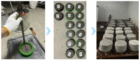
Figure 1.
Preparation procedure of reinforced concrete (RC) specimens.
2.2. Experimental Setup and Procedure
The principle of the electromigration method and the experimental apparatus are illustrated in Figure 2. The apparatus consisted of a DC power supply, power cables, anode plates, cathode plates, specimen sleeves, stainless steel clamps, specimen holders, and a cathode solution tank. Both the anode and cathode plates were made of stainless steel. The anolyte was a 0.3 M NaOH solution, and the catholyte was a 10% by mass NaCl solution. The 10% NaCl solution provides an ample source of aggressive ions, while the 0.3 M NaOH solution prevents the leaching of calcium hydroxide from the concrete specimen into the anolyte. This ensures that the experiment is conducted under consistent and controlled electrochemical conditions [24,25].
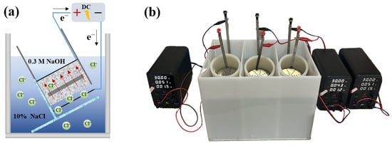
Figure 2.
The experimental setup: (a) schematic diagram of the principle; (b) photograph of the apparatus.
The experimental procedure involved the following main steps. First, the cured specimens were removed from the curing room and subjected to vacuum saturation. Subsequently, each specimen was placed into a sleeve and securely fastened with stainless steel clamps to prevent leakage and short-circuiting between the catholyte and anolyte. The rubber sleeve containing the specimen was then mounted in the cathode solution tank at an angle of 30 degrees. After the anode and cathode plates were installed, the power was switched on.
To compare the effects of different perforation areas and configurations on chloride migration behavior, five types of electrode plates were designed. As shown in Figure 3, the perforation areas of plates A through E were 5.5%, 15%, 25.5%, 38.1%, and 13.2% of the total plate area, respectively. The perforations on plates A to D were arranged symmetrically, while those on plate E had an asymmetrical arrangement.

Figure 3.
Electrode plates with different perforation ratios and configurations.
2.3. Acid Pickling of Reinforcement and Visualization of Chloride Penetration
As illustrated in Figure 4, the reinforced concrete specimens, after undergoing electromigration-accelerated deterioration, were removed from their sleeves and split along the longitudinal axis of the steel reinforcement. After splitting, the freshly exposed cross-sections were sprayed with a silver nitrate (AgNO3) solution (0.1 mol/L). The reaction between chloride and silver ions forms a white precipitate of silver chloride (AgCl), which makes the chloride penetration front visible. The specimen was split along a diametrical plane, and this surface is divided into 10 equal sections. The penetration profile was then traced using a waterproof marker. Based on the distinct color change observed, the distance from the specimen surface to the colorimetric boundary was measured at 10 mm intervals, and the average value was calculated. If a measurement point was obstructed by an aggregate, the point was moved to the nearest unobstructed location for the measurement. If a measurement at a specific point could not be obtained, this point was disregarded, provided that the total number of valid measurement points was greater than five. Furthermore, a 10% hydrochloric acid (HCl) solution was used to remove the corrosion products from the rebar surface, facilitating the observation of the surface corrosion morphology.
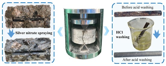
Figure 4.
Acid pickling of reinforcement and visualization of chloride penetration.
3. Results and Discussion
3.1. Non-Uniform Corrosion Characteristics of Steel Reinforcement
Figure 5a,b show the corrosion state of the steel reinforcement after 114 h of accelerated deterioration under an applied DC voltage of 15 V. It can be clearly observed that corrosion occurred exclusively on the side of the rebar facing the cathode. The applied DC voltage significantly accelerated the migration of chloride ions within the concrete’s pore structure. Under the influence of the electric field, chloride ions migrated directionally at an enhanced rate from the upper cathode region, which contained the NaCl solution, towards the surface of the steel reinforcement. Although the rebar surface is typically protected from corrosion by a dense passive film, this film is disrupted when the chloride ion concentration reaches a certain critical threshold [31].
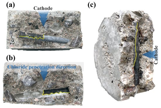
Figure 5.
Corrosion appearance of steel reinforcement. (a) rebar after 114 h of testing at 15 V; (b) rust stains on the concrete specimen; (c) rebar after 48 h of testing at 30 V.
Similarly, Figure 5c displays the corrosion condition of the reinforcement after 48 h of accelerated deterioration under a 30 V DC voltage. Within just 48 h, the electric field accelerated the directional migration of chloride ions, causing the chloride concentration on the side of the rebar nearer to the cathode to become significantly higher than on the side farther away. The high concentration of chlorides in this region was the first to disrupt the passive film on the rebar, leading to the preferential initiation of the electrochemical corrosion reaction there. As seen in the figure, the corroded area on the rebar surface, marked by a yellow dashed line, appears dark brown. Inside the concrete, these corrosion products can also cause discoloration of the surrounding matrix, which takes on a color similar to that of the rust. This reflects the typical color of reinforcement corrosion products within a moist, chloride-rich, and oxygen-limited concrete environment. The dark corrosion product is inferred to be primarily composed of magnetite (Fe3O4). This form of iron oxide typically forms in environments with an insufficient oxygen supply. During the process of electrically accelerated corrosion, the rapid consumption of oxygen by the corrosion reaction creates a relatively anoxic microenvironment near the steel rebar surface, which is conducive to the formation of magnetite [37]. When the internal stress generated by the volumetric expansion of these corrosion products exceeds the tensile strength of the concrete, radial microcracks are initiated in the concrete surrounding the rebar. As corrosion continues, these microcracks propagate, widen, and eventually extend along the direction of the reinforcement to the concrete surface, forming visually apparent corrosion-induced cracks [32]. Under natural conditions, the corrosion of steel reinforcement in concrete is a slow electrochemical process, and the color and composition of its corrosion products are characterized by diversity and complexity. The products of natural corrosion are typically reddish-brown or orange. In the initial stages of corrosion, particularly under conditions of insufficient oxygen supply, a green intermediate product known as “green rust” may form. However, this product is unstable and will gradually oxidize into more stable, reddish-brown rust [37].
Figure 6a displays the corrosion morphology of the steel reinforcement before acid pickling. The left side shows the surface that was facing the source of chloride ingress, while the right side shows the surface that was facing the anode. The rebar surface on the cathode-facing side is severely corroded, with the rust layer appearing flaky or in blocks, and it is loose and easily detached. In stark contrast, the rebar surface on the anode-facing side is intact and has not undergone corrosion. Figure 6b shows the corrosion morphology after acid pickling, with the left side depicting the surface that faced the source of chloride ingress. As can be seen, the rebar surface is in an extremely uneven, pitted, and cratered state. Numerous corrosion pits of varying sizes and significant depths are visible. The metal loss is highly non-uniform; some areas are deeply corroded by chloride ions, while adjacent areas may be slightly better, but overall, the original smooth surface no longer exists. The effective diameter of the rebar has been significantly reduced, and its cross-sectional shape has become irregular. Compared to the left side, the surface of the rebar on the anode-facing side is much smoother and more uniform, without the dense pitting seen on the left. Statistical analysis of the data in Figure 6b indicates that the average corrosion pit density on the semi-cylindrical surface of the steel bar facing the anode was approximately 40 pits/cm2, whereas the density on the surface facing the cathode was approximately 398 pits/cm2. Therefore, the corrosion pit density on the side facing the chloride source was approximately 10 times that of the side facing away from the source.
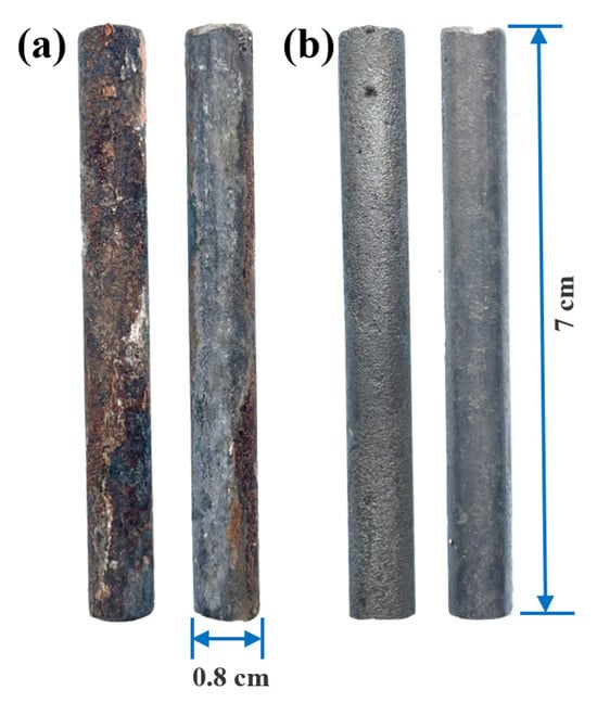
Figure 6.
Steel reinforcement before and after acid pickling: (a) before pickling; (b) after pickling.
3.2. Degree of Corrosion of Steel Reinforcement at Different Acceleration Durations
Figure 7 displays the colorimetric results from the cross-sections of specimens subjected to a 15 V DC electric field for different durations. The specimens were split and sprayed with a silver nitrate solution to visualize chloride penetration. Figure 7a shows that after 48 h, the chloride penetration front had not yet reached the steel reinforcement surface, and no corrosion was observed on the rebar. This indicates that the applied electric field itself does not cause corrosion before the arrival of chloride ions. As the test duration increased, chloride ions migrated towards the rebar surface. Corrosion initiated when the chloride concentration at the steel surface reached a critical threshold, disrupting the passive film. However, parts of the rebar where the chloride concentration remained low showed no significant corrosion. In Figure 7b, the red curve marking the chloride penetration front is very close to the rebar, yet corrosion has not appeared on the steel surface beneath it. After 186 h (Figure 7c), chlorides had penetrated the entire concrete cross-section, and significant corrosion was evident across the rebar surface.
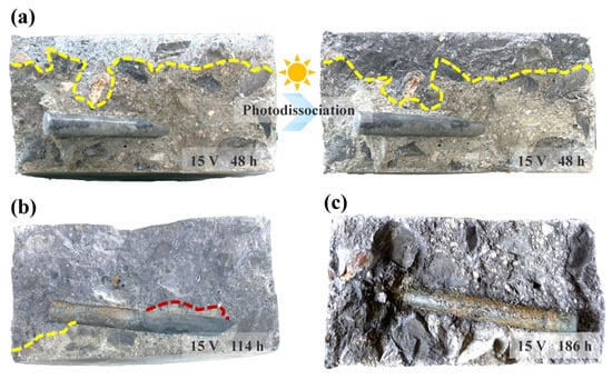
Figure 7.
Cross-sections of specimens subjected to a 15 V DC voltage for different durations: (a) after 48 h; (b) after 114 h; (c) after 186 h.
Additionally, after being sprayed with the silver nitrate solution, the white silver chloride precipitate formed on the concrete surface gradually turns dark purple due to photodecomposition. This phenomenon can be utilized to determine the chloride penetration front more accurately. On one hand, the pale white precipitate near the boundary can be easily confused with the greyish-white concrete matrix. On the other hand, white aggregates are often present within the concrete. After photodecomposition, the chloride penetration front becomes much more distinct. Although the silver nitrate colorimetric method is well-established, the determination of the chloride penetration front is subject to a degree of uncertainty. Inconsistent criteria for front demarcation among different researchers, coupled with variations in visual acuity and experience, can lead to systematic bias. The intensity, color temperature, and angle of ambient lighting can significantly influence color perception, thereby altering the judgment of the boundary. Furthermore, the roughness, moisture content, and pore structure of the specimen surface can affect the diffusion and reaction of the reagent, leading to a blurred or irregular boundary and increasing the difficulty of interpretation. Photographing the color-developed cross-sections under standardized lighting conditions and employing digital image analysis to determine the chloride penetration front would be beneficial for minimizing such errors.
It should be noted that during the vibration and casting of the concrete specimens, the steel reinforcement inevitably settles, with the angle and distance of settlement varying between specimens. Consequently, the thickness of the concrete cover is not uniform across a single batch, which leads to variations in the corrosion initiation time. Future research should aim to ensure a consistent concrete cover thickness. This would allow for the precise quantification of the corrosion rate under a given electric field strength by setting different acceleration durations. Furthermore, the adoption of scientifically sound and effective testing methods to acquire chloride concentration profiles is crucial for establishing a relational model between the progression of steel reinforcement corrosion and the behavior of chloride ingress. This is an area that warrants attention in future research.
3.3. Effect of Electrode Plate Perforation Area and Distribution Pattern on Chloride Transport
As shown in Figure 3, stainless steel was selected as the electrode material due to its excellent corrosion resistance in the highly alkaline (e.g., NaOH) and high-chloride (e.g., NaCl) solutions used for testing. This ensures the stability and reusability of the electrodes throughout the testing process. Simultaneously, the perforated electrode plate design provides an escape channel for gases generated during electrolysis. This prevents the accumulation of gas bubbles between the electrode plate and the concrete surface, ensuring good and uniform contact between the electrolyte and the specimen, and maintaining a stable and uniform distribution of the current and electric field. To investigate the influence of different perforation areas and configurations on chloride migration behavior, accelerated electromigration tests were conducted using the five types of electrode plates shown in Figure 3. To avoid any interference from steel reinforcement, plain concrete specimens were used in these tests.
Figure 8 compares the average chloride penetration depths in concrete specimens tested under the same voltage and duration but with four different electrode perforation ratios. For a perforation ratio of 5.5%, the average chloride penetration depth was 1.63 cm. The average depths for the four different perforation ratios were 1.63 cm, 1.67 cm, 1.57 cm, and 1.57 cm, respectively. Based on the overall average of all data (approx. 1.61 cm), the maximum deviation is only about 6%. In tests involving a heterogeneous material like concrete, such a range of fluctuation can be considered relatively small.
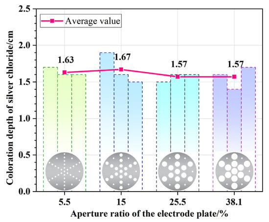
Figure 8.
Chloride penetration depths in concrete specimens tested with electrode plates of various perforation ratios.
Furthermore, to study the effect of perforation distribution uniformity on chloride transport, a test was conducted under identical conditions using an asymmetrically perforated electrode plate (Plate E in Figure 3). Figure 9 compares the chloride penetration profiles in concrete specimens tested with the symmetrical Plate D and the asymmetrical Plate E. It is clearly evident that the asymmetrical distribution of perforations resulted in a slanted and irregular penetration front. Since the migration rate of chloride ions is directly related to the current density, a non-uniform current distribution directly leads to asynchronous migration of chloride ions within the concrete.
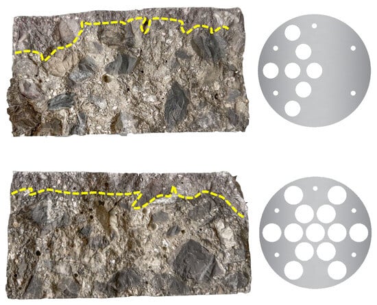
Figure 9.
Chloride penetration profiles of concrete specimens tested with electrode plates having different perforation patterns.
3.4. Effect of the Distance Between the Electrode Plate and Concrete Specimen on Chloride Transport
In the cathode solution tank, the electrode plate is fixed onto the specimen holder with supporting pillars before the concrete specimen is installed. This creates a distance, D, between the cathode plate and the bottom surface of the specimen, which also corresponds to the thickness of the catholyte layer beneath the specimen (Figure 10). To determine the influence of D on chloride transport behavior, three sets of tests were conducted, with the distance between the cathode plate and the specimen’s bottom surface set to 0.5 cm, 1 cm, and 1.5 cm, respectively.
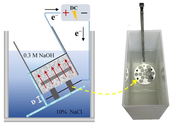
Figure 10.
Arrangement of the cathode plate and concrete specimen.
Figure 11 compares the average chloride penetration depths in concrete specimens after electromigration tests conducted at these different distances. When the distance D was 0.5 cm and 1.5 cm, the average chloride penetration depths were 1.87 cm and 1.7 cm, respectively. It is evident that the distance between the electrode plate and the concrete specimen has a negligible effect on chloride transport. The electrical resistance of the concrete specimen is the dominant component of the total system resistance. Therefore, the minor change in the electrolyte’s resistance caused by varying the electrode–specimen distance has an insignificant impact on the total resistance of the system, and the magnitude of this change is far smaller than the inherent experimental error of the test method itself.
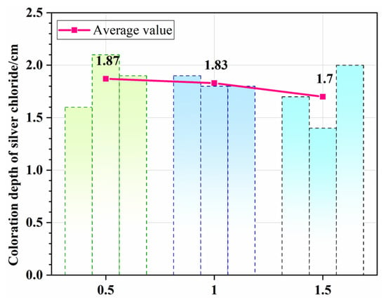
Figure 11.
Effect of the distance between the cathode plate and the concrete specimen on the chloride penetration depth.
4. Conclusions
This paper investigated the electromigration-based accelerated deterioration method and experimental parameters for steel reinforcement in concrete linings. The main conclusions are as follows:
(1) Under the acceleration of a DC electric field, chloride ions migrate directionally and preferentially accumulate on the side of the steel reinforcement facing the cathode (the chloride source). This leads to significant non-uniform corrosion: the side facing chloride ingress exhibits severe corrosion, characterized by a loose rust layer with numerous deep and irregular pits, resulting in an irregular reduction in the rebar’s effective cross-section, while the leeward side remains almost entirely intact. This phenomenon clearly demonstrates that the localized accumulation of high-concentration chlorides, accelerated by the electric field, is the primary cause of severe pitting and non-uniform damage to the reinforcement.
(2) The study confirms that corrosion is not initiated directly by the applied electric field, but rather commences only after chloride ions migrate to the rebar surface, reach a critical threshold concentration, and disrupt the passive film. As the acceleration duration increases, the extent of chloride penetration expands, and the degree of corrosion intensifies, which can eventually lead to corrosion across the entire rebar surface. Furthermore, inconsistency in the concrete cover thickness is a key variable affecting the corrosion initiation time, highlighting the need for higher precision in specimen preparation for quantitative studies.
(3) While the electrode plates are perforated with uniformly distributed holes to allow for essential ion exchange and gas release, the specific perforation ratio is not a decisive factor affecting the final measured penetration depth. However, it is imperative that the perforations are distributed uniformly and symmetrically to ensure the formation of a uniform electric field across the entire concrete specimen’s cross-section, which is a prerequisite for obtaining accurate and reliable experimental results.
(4) The distance between the electrode plate and the specimen is not a sensitive parameter in electromigration testing, and minor variations do not significantly affect the test results. Although changing this distance alters the thickness of the electrolyte layer, the contribution of this change to the total system resistance is minimal. Consequently, the total current and the effective electric field strength applied to the concrete specimen remain constant, resulting in a negligible impact on the chloride migration rate and the final penetration depth.
(5) A limitation of the present study is the lack of quantitative testing on the relationship between the rebar corrosion process and the behavior of chloride ingress. Future research should focus on developing precise methods for measuring chloride concentration profiles within concrete and for ensuring the accurate placement of steel reinforcement. The influence of variations in the concrete cover depth on the corrosion initiation time and subsequent progression warrants further investigation. This is crucial for establishing a quantitative model that relates the progression of rebar corrosion to the behavior of chloride ingress. Furthermore, once corrosion has initiated, the precise quantification of the accelerating effect of the applied electric field on the rebar corrosion process remains a key issue for future investigation.
Author Contributions
Conceptualization, J.L. and H.G.; methodology, J.L., Q.C., and H.G.; validation, S.Z. and X.L.; formal analysis, S.Z., L.W., and M.H.; investigation, J.L. and H.G.; resources, Q.C. and H.G.; data curation, Q.C. and Y.X.; writing—original draft preparation, J.L., Q.C., H.G., and Y.X.; writing—review and editing, S.Z., X.L., and L.W.; visualization, H.G. and M.H.; supervision, J.L. and H.G.; project administration, J.L. and H.G. All authors have read and agreed to the published version of the manuscript.
Funding
This research was funded by the Key Program of CCCC (No. 2022-ZJKJ-10 and No. 2024-ZJKJ-04).
Data Availability Statement
The original contributions presented in this study are included in the article; further inquiries can be directed to the corresponding author.
Conflicts of Interest
Authors Jiguo Liu, Qinglong Cui, Shengbin Zhang, Xin Li, and Longhai Wei were employed by the company CCCC Second Highway Consultants Co., Ltd. The remaining authors declare that the research was conducted in the absence of any commercial or financial relationships that could be construed as a potential conflict of interest.
References
- Gong, H.M.; Xue, Y.G.; Fu, K.; Kong, F.M.; Han, M.; Zhou, B.H.; Guo, Y.B. Assessing and predicting surrounding rock settlement troughs in the subsea tunnel: A case study of Haicang Tunnel. Mar. Georesources Geotechnol. 2024, 43, 1115–1126. [Google Scholar] [CrossRef]
- Zhang, Y.T.; Wang, M.N.; Yu, L.; Guo, X.H.; Wang, Z.H.; Li, C.H. Experimental and numerical research on the influence of steel arch frame corrosion on security of supporting system in subsea tunnel. Tunn. Undergr. Space Technol. 2022, 120, 16. [Google Scholar] [CrossRef]
- Li, P.F.; Zhou, X.J. Mechanical behavior and shape optimization of lining structure for subsea tunnel excavated in weathered slot. China Ocean Eng. 2015, 29, 875–890. [Google Scholar] [CrossRef]
- Tian, S.M.; Zhang, Y.T.; Wang, M.N. The corrosion expansion force and cracking separation between corroded section steel arch frame and shotcrete in tunnel primary support. Eng. Fail. Anal. 2024, 166, 17. [Google Scholar] [CrossRef]
- Shen, W.; Ran, J.H.; Fan, L.; Sun, B.Y.; Zhang, R.L. Investigation of macro-cell corrosion in rebar within cracked concrete beams under sustained loading conditions in the simulated marine environment. Constr. Build. Mater. 2025, 468, 16. [Google Scholar] [CrossRef]
- He, Z.S.; He, C.; Ma, G.Y.; Wang, S.M.; Huang, X. Experimental investigation on the deterioration process and spatial variation of corrosion damage of RC segmental specimens under sustained load. Constr. Build. Mater. 2022, 349, 16. [Google Scholar] [CrossRef]
- Feng, K.; Yang, R.J.; Geng, J.Y.; Cao, X.P.; He, C.A.; Yang, W.Q.; Zhang, H.H. Experimental investigation of mechanical-performance deterioration of HFRC segment under combined effect of sustained loading and chloride-induced corrosion. Tunn. Undergr. Space Technol. 2021, 114, 14. [Google Scholar] [CrossRef]
- He, Z.S.; He, C.; Kang, X.Y.; Huang, X.; Wang, S.M. Assessment of structural performance of super large cross-section subsea RC shield tunnels: Emphasis on the combined effects of highly hydrostatic pressure and corrosion-induced deterioration. Ocean Eng. 2023, 288, 15. [Google Scholar] [CrossRef]
- Liu, J.G.; Wei, L.H.; Cui, Q.L.; Shu, H.; Peng, W.B.; Gong, H.M.; Xue, Y.G.; Han, M. Chloride Corrosion Resistance of Steel Fiber-Reinforced Concrete and Its Application in Subsea Tunnel Linings. Coatings 2025, 15, 25. [Google Scholar] [CrossRef]
- Wang, M.N.; Zhang, Y.T.; Yu, L.; Dong, Y.C.; Tian, Y.; Zhou, G.J. Experimental Study on Bond-Slip Behavior between Corroded I-Shaped Steel and Concrete in Subsea Tunnel. Materials 2019, 12, 2863. [Google Scholar] [CrossRef]
- El Maaddawy, T.A.; Soudki, K.A. Effectiveness of impressed current technique to simulate corrosion of steel reinforcement in concrete. J. Mater. Civ. Eng. 2003, 15, 41–47. [Google Scholar] [CrossRef]
- Deng, Q.; Wang, Z.X.; Li, S.H.; Yu, Q.L. Salt scaling resistance of pre-cracked ultra-high performance concrete with the coupling of salt freeze-thaw and wet-dry cycles. Cem. Concr. Compos. 2024, 146, 18. [Google Scholar] [CrossRef]
- Frazao, C.; Barros, J.; Camoes, A.; Alves, A.C.; Rocha, L. Corrosion effects on pullout behavior of hooked steel fibers in self-compacting concrete. Cem. Concr. Res. 2016, 79, 112–122. [Google Scholar] [CrossRef]
- Hwang, J.P.; Jung, M.S.; Kim, M.; Ann, K.Y. Corrosion risk of steel fibre in concrete. Constr. Build. Mater. 2015, 101, 239–245. [Google Scholar] [CrossRef]
- Clemente, S.J.C.; Lejano, B.A.; Ongpeng, J.M.C. Corrosion behavior analysis of self-compacting concrete using impressed current and rapid chloride penetration test. Int. J. GEOMATE 2023, 24, 76–83. [Google Scholar] [CrossRef]
- Berrocal, C.G.; Lundgren, K.; Löfgren, I. Corrosion of steel bars embedded in fibre reinforced concrete under chloride attack: State of the art. Cem. Concr. Res. 2016, 80, 69–85. [Google Scholar] [CrossRef]
- Mangat, P.S.; Gurusamy, K. Chloride diffusion in steel fiber reinforced marine concrete. Cem. Concr. Res. 1987, 17, 385–396. [Google Scholar] [CrossRef]
- Marcos-Meson, V.; Fischer, G.; Solgaard, A.; Edvardsen, C.; Michel, A. Mechanical Performance of Steel Fibre Reinforced Concrete Exposed to Wet-Dry Cycles of Chlorides and Carbon Dioxide. Materials 2021, 14, 2642. [Google Scholar] [CrossRef] [PubMed]
- Jiang, J.H.; Yuan, Y.S. Prediction model for the time-varying corrosion rate of rebar based on micro-environment in concrete. Constr. Build. Mater. 2012, 35, 625–632. [Google Scholar] [CrossRef]
- Shakouri, M.; Vaddey, N.P.; Trejo, D. Effect of Admixed and External Chlorides on Transport of Chlorides in Concrete. ACI Mater. J. 2019, 116, 119–128. [Google Scholar] [CrossRef]
- Spiesz, P.; Brouwers, H.J.H. The apparent and effective chloride migration coefficients obtained in migration tests. Cem. Concr. Res. 2013, 48, 116–127. [Google Scholar] [CrossRef]
- Pontes, J.; Real, S.; Bogas, J.A. The rapid chloride migration test as a method to determine the chloride penetration resistance of concrete in marine environment. Constr. Build. Mater. 2023, 404, 11. [Google Scholar] [CrossRef]
- Jain, J.A.; Neithalath, N. Chloride transport in fly ash and glass powder modified concretes—Influence of test methods on microstructure. Cem. Concr. Compos. 2010, 32, 148–156. [Google Scholar] [CrossRef]
- Tang, L.P.; Nilsson, L.O. Rapid-determination of the chloride diffusivity in concrete by applying an electrical-field. ACI Mater. J. 1992, 89, 49–53. [Google Scholar]
- Tang, L. Electrically accelerated methods for determining chloride diffusivity in concrete—Current development. Mag. Concr. Res. 1996, 48, 173–179. [Google Scholar] [CrossRef]
- Wang, Y.Z.; Fu, K. Comparisons of instantaneous chloride diffusion coefficients determined by RCM method and chloride natural diffusion test. Constr. Build. Mater. 2019, 223, 595–604. [Google Scholar] [CrossRef]
- Wang, S.Q.; Cao, J.Z.; Gong, F.Y.; Peng, Y.Z.; Wang, Z.; Zhao, Y.X.; Zeng, B. Insights on the multiple ions distribution in concrete under stray current: From experiments to multi-field simulation. J. Build. Eng. 2024, 98, 15. [Google Scholar] [CrossRef]
- Kribes, Z.E.; Cherif, R.; Ait-Mokhtar, A. Modelling of Chloride Transport in the Standard Migration Test including Electrode Processes. Materials 2023, 16, 6200. [Google Scholar] [CrossRef] [PubMed]
- Liu, Q.F.; Shen, X.H.; Savija, B.; Meng, Z.Z.; Tsang, D.C.W.; Sepasgozar, S.; Schlangen, E. Numerical study of interactive ingress of calcium leaching, chloride transport and multi-ions coupling in concrete. Cem. Concr. Res. 2023, 165, 15. [Google Scholar] [CrossRef]
- Fu, C.Q.; Zhang, J.H.; Yu, N.T.; Yuan, W.B.; Gao, Z.J. Reliability of chloride diffusion coefficients calculated from rapid chloride migration experiments. Mag. Concr. Res. 2025, 77, 809–818. [Google Scholar] [CrossRef]
- Shi, J.J.; Ming, J.; Sun, W. Accelerated Corrosion Behavior of Steel in Concrete Subjected to Sustained Flexural Loading Using Electrochemical Methods and X-Ray Computed Tomography. J. Mater. Civ. Eng. 2018, 30, 2337. [Google Scholar] [CrossRef]
- Wei, L.H.; Liu, J.G.; Shu, H.; Cui, Q.L.; Peng, W.B.; Gong, H.M.; Xue, Y.G.; Han, M. Degradation Characteristics and Mechanisms of Steel Fiber-Reinforced Concrete Linings in Subsea Tunnels: Insights from Accelerated Erosion Tests with Applied Electric Fields. J. Mar. Sci. Eng. 2025, 13, 18. [Google Scholar] [CrossRef]
- Geng, C.L.; Xu, Y.M.; Weng, D. A New Method to Quickly Assess the Inhibitor Efficiency. J. Wuhan Univ. Technol.-Mater. Sci. Ed. 2008, 23, 950–954. [Google Scholar] [CrossRef]
- Jin, N.G.; He, J.H.; Fu, C.Q.; Jin, X.Y. Study on experimental method and morphology of accelerated non-uniform corrosion of steel bars. J. Zhejiang Univ. Eng. Sci. 2020, 54, 483–490. [Google Scholar]
- Fu, C.Q.; Jin, N.G.; Ye, H.L.; Liu, J.M.; Jin, X.Y. Non-uniform corrosion of steel in mortar induced by impressed current method: An experimental and numerical investigation. Constr. Build. Mater. 2018, 183, 429–438. [Google Scholar] [CrossRef]
- Zhang, L.; Niu, D.T.; Wen, B.; Luo, D.M. Concrete Protective Layer Cracking Caused by Non-Uniform Corrosion of Reinforcements. Materials 2019, 12, 4245. [Google Scholar] [CrossRef] [PubMed]
- Feng, W.P.; Tarakbay, A.; Memon, S.A.; Tang, W.C.; Cui, H.Z. Methods of accelerating chloride-induced corrosion in steel-reinforced concrete: A comparative review. Constr. Build. Mater. 2021, 289, 14. [Google Scholar] [CrossRef]
- Michel, A.; Solgaard, A.O.S.; Pease, B.J.; Geiker, M.R.; Stang, H.; Olesen, J.F. Experimental investigation of the relation between damage at the concrete-steel interface and initiation of reinforcement corrosion in plain and fibre reinforced concrete. Corros. Sci. 2013, 77, 308–321. [Google Scholar] [CrossRef]
- Liu, Q.F.; Su, R.K.L. A Wasserstein distance-based analogous method to predict distribution of non-uniform corrosion on reinforcements in concrete. Constr. Build. Mater. 2019, 226, 965–975. [Google Scholar] [CrossRef]
- Feng, T.T.; Yu, H.F.; Tan, Y.S.; Ma, H.Y.; Xu, M.; Yue, C.J. Service Life Design for Concrete Engineering in Marine Environments of Northern China Based on a Modified Theoretical Model of Chloride Diffusion and Large Datasets of Ocean Parameters. Engineering 2022, 17, 123–139. [Google Scholar] [CrossRef]
- Liu, Q.F.; Pei, G.D.; Hou, H.T.; Chen, Y.Q. Probabilistic similarity of non-uniform corrosion pattern between natural corrosion and accelerated experiment. Constr. Build. Mater. 2023, 392, 15. [Google Scholar] [CrossRef]
- Xi, X.; Yang, S.T.; Li, C.Q. A non-uniform corrosion model and meso-scale fracture modelling of concrete. Cem. Concr. Res. 2018, 108, 87–102. [Google Scholar] [CrossRef]
- Liu, Q.F.; Chen, Y.Q.; Ge, Y.; Xiong, Q.R.; Ma, J.L.; Wang, Y.K.; Zhang, F.L. Time-dependent non-uniform corrosion of concrete structures under marine environments considering the vertical variation of exposure conditions. Ocean Eng. 2024, 306, 20. [Google Scholar] [CrossRef]
Disclaimer/Publisher’s Note: The statements, opinions and data contained in all publications are solely those of the individual author(s) and contributor(s) and not of MDPI and/or the editor(s). MDPI and/or the editor(s) disclaim responsibility for any injury to people or property resulting from any ideas, methods, instructions or products referred to in the content. |
© 2025 by the authors. Licensee MDPI, Basel, Switzerland. This article is an open access article distributed under the terms and conditions of the Creative Commons Attribution (CC BY) license (https://creativecommons.org/licenses/by/4.0/).