Abstract
This study presents a numerical investigation into the structural behavior of a pile-in-pile (PIP) slip joint utilizing square hollow section (SHS) members, with a comparative assessment against conventional circular hollow sections (CHSs). A comprehensive finite element model was developed and validated against published CHS experimental results to evaluate key performance indicators, including stress distribution, buckling behavior, and load-carrying capacity under pure bending, axial compression, and diagonal lateral loads. The analysis revealed that SHS joints demonstrated distinct stress concentration patterns and higher capacity under axial compression, whereas CHS joints provided superior performance under bending due to their geometric symmetry. However, SHS corners were more vulnerable under diagonal loading, exhibiting localized buckling at relatively lower loads. These structural weaknesses can be mitigated through design improvements, such as increased wall thickness or corner strengthening. The findings highlight that while SHSs introduce certain vulnerabilities compared to CHSs, they also offer advantages in axial load resistance, supporting their potential as a viable alternative for offshore wind foundation connections.
1. Introduction
The global transition toward renewable energy has placed offshore wind at the forefront of sustainable electricity generation. Offshore wind turbines (OWTs) are increasingly being designed for greater power capacities and deployed in deeper waters, which requires reliable, durable, and cost-efficient foundation systems capable of withstanding harsh marine environments [1,2,3]. Among the various foundation solutions, such as jackets, gravity-based structures, and floating platforms, monopiles have emerged as the most widely adopted due to their structural simplicity, ease of fabrication, and cost-effective installation procedures [4,5,6]. Over the last two decades, monopiles have accounted for more than 70% of installed offshore wind turbine foundations worldwide, demonstrating their dominant role in the sector [7,8].
Despite their widespread application, monopiles face several engineering challenges, particularly with respect to structural connections. Traditional joints, including welded and bolted connections, often introduce fabrication complexity, extended construction times, and increased susceptibility to fatigue and corrosion under cyclic loading from waves, wind, and currents [9,10]. One of the widely used conventional joint systems is the bolted flange joint, which facilitates modular assembly and improved structural efficiency in offshore support structures [11,12,13]. However, bolted joints in wind turbine towers are prone to fatigue failure, bolt loosening, and corrosion due to constant cyclic loads. These issues are compounded by the complex and costly installation and maintenance required to ensure joint integrity over the tower’s lifespan. These limitations hinder the overall structural reliability and impose significant costs during both installation and maintenance. Consequently, research has shifted toward exploring innovative connection concepts that can enhance structural robustness while reducing construction and lifecycle costs.
A promising alternative is the pipe-in-pipe (PIP) slip joint, which consists of two overlapping tubular members that transfer load primarily through frictional resistance [14,15,16]. This arrangement eliminates the need for extensive bolting or welding, thereby simplifying installation and reducing on-site labor. Moreover, PIP slip joints demonstrate inherent self-aligning properties, enabling easier turbine assembly at sea while also redistributing stresses to improve structural resilience against dynamic environmental loads [17,18]. Experimental and numerical studies on circular hollow section (CHS) slip joints have highlighted their effectiveness under combined axial and bending loads, confirming their potential as a cost-effective and structurally robust alternative to conventional connections [15,19]. A PIP slip joint consists of two overlapping tubular members, where the outer pile accommodates an inner pile with a designed overlapping length, as shown in Figure 1. Load transfer between the members occurs primarily through frictional resistance and contact pressure, and the ring stopper resists the axial compression due to the self-weight of the turbine and environmental loading [18]. This mechanism eliminates the need for extensive welding or bolting and enables a self-locking, self-aligning connection, which simplifies installation procedures at sea.
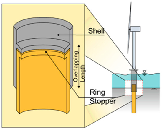
Figure 1.
The different components of a PIP slip joint.
However, the application of PIP slip joints has predominantly been investigated in the context of CHS geometries, leaving other tubular profiles underexplored. In particular, SHSs offer distinct advantages that could further improve fabrication and structural performance. SHSs play a critical role in offshore and high-velocity structural applications due to their beneficial fluid dynamic characteristics. Research shows that closed hollow sections—like SHSs—exhibit lower drag coefficients than open or sharp-edged profiles. This is particularly evident under high wind or current conditions where drag forces are significant [20]. From an aerodynamic viewpoint, flow experiments on square prisms reveal that rounded corner radius substantially alters drag and lift characteristics. For instance, transitioning from sharp edges towards a rounded geometry reduces drag, suppresses vortex shedding, and enhances flow stability—especially at high Reynolds numbers [21,22]. The smoother flow behavior around rounded SHSs improves aerodynamic efficiency and mitigates oscillatory loads. Moreover, SHS geometries may facilitate modular construction approaches, which are becoming increasingly relevant for large-scale offshore projects. Nonetheless, SHS members are also prone to local buckling at the corners, raising concerns about their load-carrying capacity under critical loading conditions [23,24,25]. This duality highlights the necessity of a rigorous investigation into the feasibility of SHS-based slip joints for offshore wind applications.
To address this research gap, this study numerically investigates the structural performance of an SHS PIP slip joint under pure bending, lateral load, and axial compression. A finite element (FE) model is developed to evaluate stress distribution, corner buckling, and load capacity, and is validated against published CHS experimental results. The findings reveal the structural vulnerabilities of SHS joints and suggest mitigation strategies, such as optimized overlap ratios and local strengthening. This work advances the understanding of PIP slip joints in non-circular geometries and highlights the SHS configuration as a promising, cost-efficient alternative for next-generation offshore monopile connections.
2. Materials and Methods
The objective of this research is to numerically investigate the structural behavior of a pipe-in-pipe (PIP) slip joint using square hollow section (SHS) members, specifically for its potential application in offshore wind monopile designs. This study focuses on key performance indicators, including local buckling, stress concentration, and load-carrying capacity under pure bending and axial compression loads. The findings are benchmarked against the behavior of a conventional circular hollow section (CHS) configuration to demonstrate the comparative advantages of the proposed design.
2.1. Material Properties and Geometry
The finite element model is developed in ANSYS (version 2025 R1) to replicate the PIP slip joint arrangement using square hollow sections (SHSs). This finite element model was independently developed within ANSYS Mechanical using custom-defined geometry, meshing, and contact parameters to replicate the PIP slip joint configuration. The model was not based on any built-in template but constructed manually using user-defined dimensions, material properties, and boundary conditions to ensure full control over the simulation parameters. The model consists of two concentric members—an inner and an outer pile—configured to capture the essential load transfer mechanism of the slip joint. The primary geometric parameters are summarized in Table 1, including the total length of the assembly (48,000 mm), the section dimensions, the wall thickness (30 mm), and the overlapping length (8000 mm).

Table 1.
Geometric properties.
For the axial compression case, the SHS geometry was derived to provide an equivalent cross-sectional area relative to the reference circular section. Accordingly, the edge length of the SHS was taken as 3148 mm with the same wall thickness of 30 mm and an overlapping length of 6296 mm, which facilitates a direct comparison of axial load-carrying capacity between CHS and SHS configurations. On the other hand, in the bending cases, the SHS dimensions were selected to provide an equivalent moment of inertia compared to the reference circular section. In this configuration, the edge length of the SHS (3360 mm) with a uniform wall thickness of 30 mm and an overlapping length of 6720 mm was defined, ensuring a consistent basis for comparing bending resistance with the CHS prototype as shown in Figure 2.
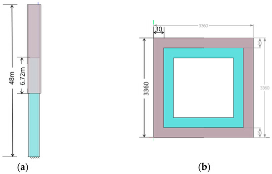
Figure 2.
(a) Length of the jack-up barge leg and (b) section of SHS used in the leg.
In all cases, the inclusion of a ring stopper (90 × 120 mm) was modeled to ensure accurate simulation of slip joint mechanics and contact behavior. The adopted modeling approach allows a systematic investigation of the structural response of SHS slip joints under different critical load scenarios, including pure bending and axial compression.
The model’s components are assigned to the properties of S-355 steel, a common material in structural engineering [26]. A bilinear isotropic hardening model was defined within the solver to capture the nonlinear material behavior, which is essential for accurately capturing material yielding and post-yield response. The key material properties, including Young’s modulus, Poisson’s ratio, and yield strength, are adopted from validated experimental studies to ensure the model’s accuracy. The developed FE model was then implemented in ANSYS Mechanical (version 2025 R1) and refined through mesh sensitivity and contact behavior analyses.
The material properties are presented in the following Table 2.
Table 2.
Material properties.
Governing Equations and Numerical Implementation
The finite element formulation adopted in this study is based on the principle of equilibrium between internal and external forces, expressed as
where
K(u) is the global stiffness matrix that varies with the displacement field, and
u and F are the external load vectors.
This nonlinear system incorporates three sources of nonlinearity; material, geometric, and contact, which are solved through an incremental iterative Newton–Raphson algorithm implemented in ANSYS Mechanical.
- (a)
- Material nonlinearity
The S-355 steel components are modeled using a bilinear isotropic hardening law to capture yielding and strain hardening. The constitutive relation is written as
where
E is the Young’s modulus, fy is the initial yield stress, and
Et is the tangent modulus obtained from the post-yield slope of the stress–strain curve.
Plastic deformation is integrated through an incremental strain-hardening scheme that updates the material stiffness matrix at each load step [27].
- (b) Contact and frictional behavior
Interaction between the inner and outer SHS members is modeled using a pressure-dependent friction coefficient to reproduce realistic slip joint behavior.
The variation in friction with contact pressure is expressed as
The coefficients a and b are listed in Table 3.
Table 3.
Frictional coefficient for pressure-dependent friction.
This model accounts for the gradual change in frictional resistance as the normal pressure increases along the overlapping interface. The augmented Lagrange method is applied to enforce contact constraints, while automatic penetration control ensures the stable convergence of the contact algorithm.
- (c) Geometric nonlinearity and buckling formulation
Large deformation effects are captured by incorporating both linear and quadratic geometric stiffness matrices [28,29]. The equilibrium of the total tangent stiffness matrix can be expressed in quadratic eigenvalue form as
Here,
Ke = initial elastic stiffness matrix,
Kgl = initial linear geometries matrix,
Kvl = respective matrices of linear displacements,
Kgn = initial geometrical stiffness matrix (quadratic form),
Kvn = initial displacement matrix (quadratic form), and
V = nodal displacements vector.
2.2. Finite Element Analysis Setup
2.2.1. Meshing
The FEA model is meshed using HEX20 solid elements. This element type is selected for its superior ability to model three-dimensional nonlinear behavior, especially in areas prone to plastic deformation and local buckling [30]. A comprehensive mesh sensitivity analysis is performed to ensure the numerical results are independent of the element size and that the solution converges reliably, as shown in Figure 3. The mesh sensitivity analysis shows that maximum displacement increases with refinement and stabilizes, indicating convergence. Coarser meshes underestimate displacement, while finer meshes capture the structural response more accurately. Across all load cases (100 kN, 300 kN, and 500 kN), the displacement values become stable at a mesh size of about 100 mm. Thus, a 100 mm mesh is considered the optimum size, providing a converged solution while maintaining reasonable computational times, as detailed in Table 4. The mesh quality, including the Jacobian ratio and skewness, is also carefully checked to ensure all elements meet the required quality standards for accurate analysis. The meshing statistics have been provided in the following Table 4.
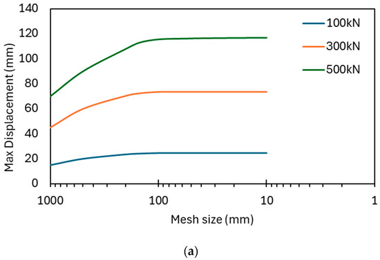
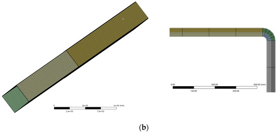
Figure 3.
(a) Mesh sensitivity analysis and (b) sample of meshing.
Table 4.
Mesh statistics.
Along with the mesh statistics, some meshing samples have also been given in the following picture.
2.2.2. Dynamic Frictional Behavior
The intricate interaction between the inner and outer piles is modeled using a nonlinear contact algorithm that allows for the continuous detection of contact status throughout the analysis. A pressure-dependent dynamic friction model is implemented to simulate the frictional contact behavior, where the friction coefficient varies based on the normal contact pressure. This approach provides a more realistic representation of the joint’s behavior than a constant static coefficient, as it accounts for the changing pressure distribution during bending and axial loads. The augmented Lagrange method is applied to manage the contact forces and ensure accurate load transfer across the joint interface, thereby capturing the effects of sliding and potential separation between the two piles. This iterative technique is known for its robustness and ability to handle large deformation problems efficiently, as the overlapping area mainly experiences the pressure from the interaction between the inner and outer shells. Therefore, dynamic pressure-dependent friction [31] has been used, as seen in the table below. In ANSYS Mechanical, an APDL command has been used to incorporate this [25]. The dynamic frictional coefficient is already given in Table 3 for the initial FEM, which is used for the framework verification.
To model pressure-dependent dynamic friction, the coefficient of friction was defined in ANSYS using APDL scripting. This approach allowed the friction coefficient to vary with contact pressure, ensuring a more realistic simulation of slip joint behavior.
2.3. Framework and Boundary Condition
2.3.1. Loading and Boundary Conditions
The model is subjected to three primary load cases: pure bending, lateral shear, and axial compression. The loads are applied incrementally to observe the structural response throughout the entire loading history. These loads are defined based on typical design conditions for monopile slip joint connections and are summarized in Table 5. They were applied incrementally to observe the structural response under different load histories. The overlapped area is placed in the middle of the jack-up barge leg system. These loads have been used separately and combinedly to understand the behavior of the section for prescribed loadings. The boundary conditions are defined using multi-physics connection (MPC) to replicate a rigid coupling connection at the supports. The frictional contact in the overlapping portion is also modeled dynamically, as detailed in the previous section, and the ring stopper details are also incorporated into the model to provide a comprehensive structural analysis. In the following Figure 4, the MPC constraints and the loading conditions (bending, axial compression, lateral loadings, and combined loading case) have been presented. The ring stopper dimensions are also provided in Figure 5.
Table 5.
Loading conditions considered in the numerical model.
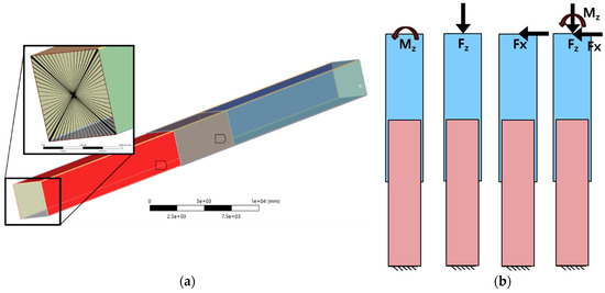
Figure 4.
(a) MPC constraints and (b) different loading conditions.
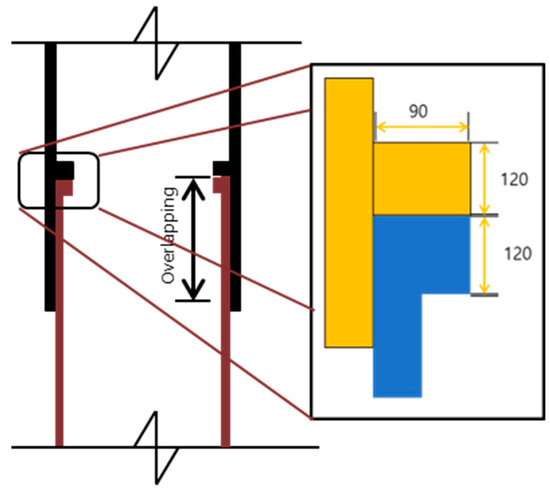
Figure 5.
Dimensions of the ring stopper.
2.3.2. Framework Verification
The numerical model was validated by comparing its force–displacement and stress–strain responses under pure bending with results from a prior experimental study on CHS slip joints [19,32]. The experimental program used a four-point bending setup with simply supported conditions and displacement-controlled loading up to 150 mm (as shown in Figure 6). To prevent premature local buckling at the supports and loading points, substantial 20 mm thick stiffeners were welded onto the specimens, a detail that was explicitly replicated in the finite element model using plate stiffeners [19].
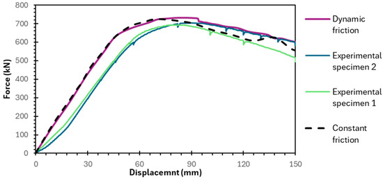
Figure 6.
Framework verification against experimental results for dynamic friction.
Key assumptions and simplifications in the numerical model, alongside experimental variabilities, were identified to contextualize the correlation:
Initial Geometric Imperfections (IGIs) and Gaps:
The numerical model assumed an ideal, perfect geometry. In contrast, the physical specimens contained initial geometric inaccuracies and minor initial gaps between the piles, leading to the observed initial slippage and approximately 5–10% variation in initial stiffness between the test specimens and the simulation [26].
Frictional Coefficient:
A constant friction coefficient of 0.4, derived from prior experimental work, was used in the simulation. In reality, this coefficient may vary with contact pressure and surface wear during the test, contributing to differences in the force–displacement curve’s profile.
Material Modeling:
The numerical model used RMS values from coupon tests for material properties to ensure robustness, whereas the actual specimen material had natural microscopic variations.
Measurement Uncertainty and Repeatability:
The experimental data’s repeatability was confirmed by testing two identical specimens, which showed nearly identical ultimate capacities (70 tons) and failure modes. The periodic drops in the experimental force–displacement curves are a direct result of the incremental, paused loading procedure employed during the physical test for safety and data acquisition purposes. However, minor variations in initial stiffness and the post-yield response were observed, attributed to the IGI effect. Furthermore, measurement uncertainties arose from strain gauge malfunctions beyond 60 mm of displacement in some locations, particularly in the tensile zone, limiting full-range validation for tensile strain.
3. Results of FEA Analysis
3.1. Pure Bending Case
In the case of pure bending, the numerical analysis of the SHS slip joint demonstrated a continuous, almost linear increase in maximum principal stress, which reached a peak of 385.25 MPa towards the end of the simulation. This value exceeds the material’s 355 MPa yield stress, indicating significant plastic deformation. In contrast, for the axial load case, the maximum principal stress showed a clear, continuous increase, reaching 124.82 MPa at the end of the simulation, which remained well within the elastic limits of the material. A key observation is that the stress concentration points consistently showed maximums over time, highlighting that these localized high-stress areas, particularly at the sharp corners and transition regions, are critical for fatigue analysis and potential crack initiation. Furthermore, the analysis of the force–displacement curve revealed that the dynamic friction model provided results that were closer to the experimental data compared to the static friction model. This confirms the importance of using a pressure-dependent friction approach for accurate simulation of the slip joint’s behavior. In Figure 7, the stress concentration in the shell near and around the ring stopper is shown.
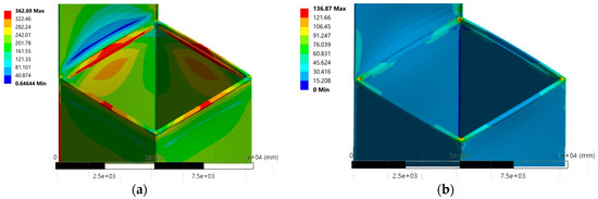
Figure 7.
(a) Locations of maximum principal stress and (b) minimum principal stress.
In the axial loading scenario, the analysis revealed that the minimum principal stress exhibits a distinctive rippling effect in the vicinity of the ring stoppers. This localized phenomenon is indicative of minor compressive stress fluctuations, which, while not leading to yielding in this particular case, highlights the complex stress distribution at these critical support points. In all pure bending cases, the maximum principal stress (σ1) reached significantly higher values, exceeding the material’s yield strength and demonstrating that compressive yielding and potential fracture are the primary failure modes for the PIP slip joint under these conditions. Furthermore, the results from the combined loading simulations revealed a clear interaction between the bending and compression effects, producing a unique stress and deformation pattern not observed in the individual loading cases. This underscores the necessity of a comprehensive structural assessment that considers all potential loading scenarios to ensure the design’s reliability and integrity. In Figure 8, the maximum and minimum stress for the different loading conditions are provided.
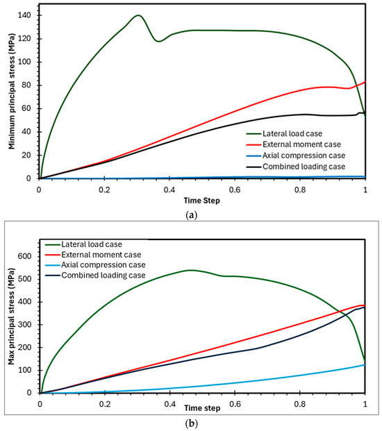
Figure 8.
Stress in the PIP slip joint arrangements (a,b).
For the pure bending case, the analysis showed that the peak von Mises stress reached 402.26 MPa. This value exceeds the material’s yield stress of 355 MPa, which indicates that plastic deformation occurred. Figure 9 illustrates that with an increasing external moment, plastic deformation spreads through the localized high-stress zones, as indicated by the stress values exceeding the yield point. In stark contrast, in the axial loading case, the stress values remained well within the material’s elastic limits, indicating a safe operational state without any permanent plastic deformation. This highlights that the PIP slip joint’s primary structural vulnerability is under bending conditions rather than axial compression. In Figure 9, the equivalent von Mises for the different loading cases are provided.
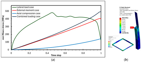
Figure 9.
Equivalent stress in the PIP slip joint arrangements (a,b).
The analysis of the axial loading case showed a strong linear relationship between normal stress and displacement, as depicted in the provided graph. This linearity is a clear indication that the SHS slip joint material remains well within its elastic range under these loads, which aligns perfectly with the previous von Mises stress analysis for axial stress. The steep, linear slope of this curve, with a maximum compression stress of around 150 MPa, directly represents the effective axial stiffness of the joint, signifying that a relatively small displacement results in a significant increase in axial stress. This demonstrates that the joint efficiently resists axial stretching or compression. From a deformation and stress perspective (Figure 10), the joint is expected to perform reliably under axial loads without significant wear or yielding.
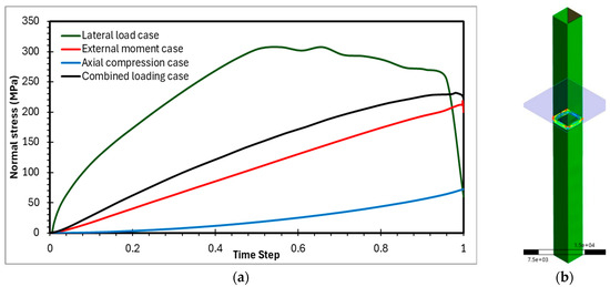
Figure 10.
Normal stress in the PIP slip joint arrangements (a,b).
In contrast, the pure bending and lateral bending cases exhibited clear nonlinear behavior, with maximum principal stresses reaching significantly higher values. This indicates that plastic deformation occurred, highlighting compressive yielding and fracture as the primary structural concerns under these bending conditions.
3.2. Contact Parameters
In a frictional slip joint, accurate contact parameters are crucial because they directly govern the joint’s function and durability. Since friction is the primary means of transferring load, precisely understanding contact pressure and the coefficient of friction is essential for predicting the joint’s load-bearing capacity and preventing design failures. Moreover, these parameters are key to predicting failure modes, as high contact pressures can lead to localized material yielding and local buckling. For long-term performance, frictional contact is a major source of wear and tear, making it vital to analyze these parameters to estimate the joint’s lifespan and the need for maintenance. Finally, for joints designed to allow for movement, such as for thermal expansion, high friction can cause the joint to lock up, compromising its functional performance and requiring excessive force to operate.
The significantly higher contact pressures and frictional stresses under bending indicate that the bending load is the primary driver of wear and potential material degradation at the slip interface. This is a major concern for the operational lifespan of the joint. If the slip joint is designed to allow for relative motion (e.g., thermal expansion/contraction, or movement due to ground settlement), the high frictional stresses during bending could prevent this intended slip, potentially locking the joint or requiring excessively large forces to overcome friction. Figure 11 is a diagram that visually explains the sliding mechanism in a pile-in-pile (PIP) connection under different loading conditions. Moreover, the graphs in Figure 12 clearly illustrate that pure bending with an external moment induces significantly higher frictional stresses and contact pressures at the slip joint interface compared to axial and combined loading. For example, the frictional stress under pure bending is approximately 14 MPa, which is considerably higher than the values for the other loading conditions. This indicates that bending loads are the primary cause of wear and potential material degradation at the slip interface. This is a major concern for the operational lifespan of the joint.
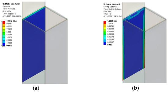
Figure 11.
(a) Sliding due to axial loading and (b) sliding in the pure bending case.
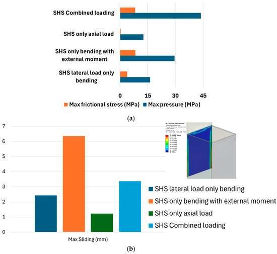
Figure 12.
(a) Frictional stress and pressure in the overlapping area and (b) max sliding in SHS.
3.3. Strengthened Section
To mitigate the identified vulnerabilities, the wall thickness was increased from 30 mm to 50 mm. This specific increment was selected to significantly reduce the section slenderness (C/t ratio from 109 to 67.2), providing an optimal balance between performance gain and material use. A parametric study confirmed that this 20 mm increase offered a decisive improvement in buckling resistance and stress reduction compared to smaller increments. This enhancement led to an increase in the section modules, resulting in a notable improvement in the joint’s performance, as demonstrated in the following results. As demonstrated in the graph, the original von Mises stress curve shows a higher stress level compared to the improved scenario’s dashed green line, which achieved a 20% reduction in stress. This decrease in stress concentration indicates a more robust and reliable design. The results suggest that, in addition to increasing the section modules, further improvements can be achieved by implementing other design changes such as increasing the overlapping length or adding local reinforcements. These measures can effectively manage and reduce stress concentrations, ultimately leading to a more reliable and durable structural design. In the following Figure 13, the comparison of the improved section and the original section is shown.
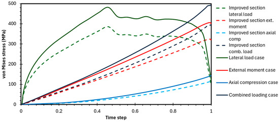
Figure 13.
Stress for strengthened section.
3.4. Comparison with CHS
After a thorough analysis of the CHS with pressure-dependent friction, it was observed that the maximum stress was localized at the bottom of the section, precisely where it met the fixed support. This is also the same point where local buckling occurred, highlighting this specific area as a critical point of failure.
The analysis also revealed a direct and linear relationship between increasing pressure and increasing frictional stress, which is an expected outcome as frictional stress is directly influenced by the normal pressure on the contact surface, as shown in Figure 14. The specific contact parameters, including the pressure and frictional stress values, are illustrated in the accompanying Figure 14. This finding underscores the importance of considering pressure-dependent friction in numerical models, as it accurately identifies the highest-stress zones and potential buckling locations, which are crucial for the integrity and safety of the design.
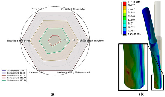
Figure 14.
(a) Key relationship for the overlapping area and (b) location of maximum stress.
An eigenvalue buckling analysis revealed that the CHSs (circular hollow sections) consistently have higher bifurcation loads across all buckling modes compared to the SHSs (square hollow sections), as shown in the provided Figure 15. This finding indicates a greater probability of buckling for the SHSs, which can be attributed to fundamental differences in their geometries. The inherent symmetry of the CHS allows for a uniform distribution of directional loads, ensuring that every point on the outer surface is equidistant from the center. In contrast, the SHS’s corners are overextended from the center, making these edges more prone to failure as each face acts separately. As a result, the SHS, which can be classified as a Type 4 section, struggles to distribute loads to adjacent surfaces due to these weak edge points, causing it to buckle more easily than the symmetrically robust CHSs.
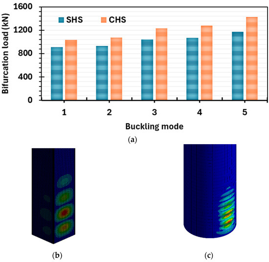
Figure 15.
Bifurcation loads for the different buckling modes. (a–c) Buckling points for SHSs and CHSs.
3.5. Effect of Diagonal Lateral Loadings in SHS
In a real-world offshore environment, lateral loads can originate from any direction, making it crucial to assess the structural integrity of the joint under diagonal loading conditions. For this reason, each of the loads was applied at a 45-degree angle to the main plane, as per Figure 16.
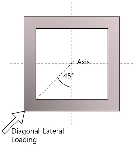
Figure 16.
Diagonal loading in SHS.
Under these diagonal loads, the leg exhibited a distinctive failure pattern characterized by local buckling exclusively at the leg’s tip. This failure occurred because the applied loading could not effectively propagate through the overlapping area. As previously noted, the edges of the SHS are more prone to buckling due to their distance from the section’s center. When the diagonal load was directed toward these vulnerable edges, local buckling occurred at a much lower load than in axial cases.
The graph in Figure 17 presents the variation in equivalent von Mises stress with time for three loading conditions: combined loading, pure bending, and lateral load. The lateral load (orange curve) shows the lowest stress response, increasing gradually to about 80 MPa before dropping slightly, while the pure bending case (green curve) produces higher stresses, reaching around 165 MPa with a steady rise. In contrast, the combined loading case (blue curve) exhibits a much more severe response, with stresses rising rapidly and peaking near 360 MPa, after which it drops sharply due to material yielding, redistribution, and instability effects. Overall, the combined loading generates stresses more than twice those from pure bending and nearly five times those from lateral loading, demonstrating the critical influence of load interaction on structural performance.
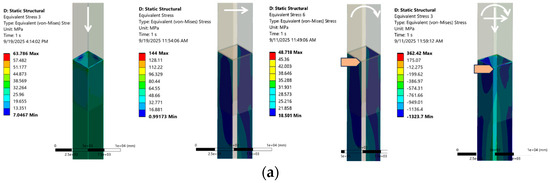
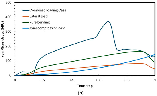
Figure 17.
(a) Maximum stress due to the different loading conditions and (b) variation in von Mises stresses.
4. Conclusions
This numerical analysis investigated the structural performance of an SHS PIP slip joint for offshore wind monopile applications, comparing its behavior to a conventional CHS design under various loading conditions. The study’s key findings highlight critical aspects of the joint’s performance and design.
Under pure bending, the SHS’s maximum equivalent von Mises stress reached 405.6 MPa, exceeding the material’s yield stress of 335 MPa and indicating plastic deformation. In stark contrast, the axial load case resulted in a stress of only 144 MPa, remaining well within the elastic range. This confirms that pure bending is the primary driver of failure for this joint. The analysis of frictional stress at the slip interface further supports this, with pure bending inducing a significantly higher stress of 8.419 MPa compared to 0.4106 MPa for axial compression, which points to greater wear and sliding resistance during bending.
The comparative analysis indicated that circular hollow sections (CHSs) generally exhibit superior resistance to buckling due to their ability to distribute loads uniformly. An eigenvalue buckling analysis confirmed that CHSs consistently have higher bifurcation loads compared to square hollow sections (SHSs), making them less susceptible to failure. However, it is essential to note that SHSs demonstrated better capacity under axial compression.
The study also highlighted the significant impact of diagonal lateral loading. These loadings consistently resulted in localized buckling, primarily due to stress concentrations at the corners of the SHSs. This pattern of failure occurred at lower loads than in axial compression, emphasizing the vulnerabilities present in the corners of the SHS design.
Finally, the research demonstrated that simple design modifications can effectively mitigate these issues. By increasing the section thickness from 30 mm to 50 mm (resulting in a C/t ratio of 67.2), a 20% reduction in von Mises stress was achieved. This proves that implementing strategic improvements—such as increasing overlapping length or adding local reinforcements—can lead to a more robust and reliable SHS joint design.
This study advances offshore slip joint research by presenting the first comprehensive numerical analysis of square hollow section (SHS) PIP slip joints under critical loading, including pure bending, axial compression, and diagonal lateral loading. The findings identify SHS-specific failure modes, notably, increased corner buckling vulnerability under diagonal loads, but also demonstrate its improved axial compression performance relative to circular hollow sections (CHSs). Validated mitigation strategies are also proposed, achieving significant stress reductions. This work expands design options, positioning SHS as a viable and advantageous solution where axial strength and fabrication efficiency are required. The study also outlines directions for future research on SHS geometry optimization and specialized design guidelines for non-circular offshore wind foundation joints.
Author Contributions
Conceptualization, M.A.I. and D.L.; methodology, M.A.I. and D.L.; soft-ware, M.A.I.; validation, M.A.I. and D.L.; investigation, M.A.I. and D.L.; data curation, M.A.I. and H.P.; writing—original draft preparation, M.A.I.; writing—review and editing, M.A.I., H.P. and D.L.; visualization, M.A.I.; supervision, D.L. All authors have read and agreed to the published version of the manuscript.
Funding
This work was supported by grants from the Korea Institute of Energy Technology Evaluation and Planning (KETEP), funded by the Ministry of Trade, Industry, and Energy of the Korean government (RS-2021-KP002506) and the Korea Institute of Energy Technology Evaluation and Planning (KETEP) grant funded by the Korean government (MOTIE) (RS-2022-KP002707, Jeonbuk Regional Energy Cluster Training of Human Resources).
Data Availability Statement
The data presented in this study is available on request from the corresponding author.
Conflicts of Interest
The authors declare no conflicts of interest.
Abbreviations
The following abbreviations are used in this manuscript:
| PIP | Pile-in-Pile |
| SHS | Square Hollow Section |
| CHS | Circular Hollow Section |
| OWTs | Offshore Wind Turbines |
| FEA | Finite Element Analysis |
| FE | Finite Element |
| KOMS | Korea Offshore Marine Solution |
| MPC | Multi-Physics Connection |
| APDL | ANSYS Parametric Design Language |
The following Nomenclatures are used in this manuscript:
| Symbol | Description | Units |
| Total length of the leg | mm | |
| Edge of the section | mm | |
| Thickness of the wall | mm | |
| Overlapping length of PIP slip joint | mm | |
| Yield stress of material | MPa | |
| Ultimate tensile strength of the material | MPa | |
| Modulus of elasticity | MPa | |
| Tangent modulus | MPa | |
| Poisson’s ratio | - | |
| Density of the material | ||
| Maximum principal Stress | MPa | |
| u | Displacement field | mm |
| External load vector | N | |
| Displacement-dependent global stiffness matrix | N/mm | |
| Strain | - | |
| Yield strain | - | |
| Stress | MPa | |
| P | Contact pressure | MPa |
| Friction coefficient | - | |
| Critical load factor (eigenvalue) | - |
References
- Islam, M.R.; Van Nguyen, D.; Park, H.; Lee, D. Nonlinear seismic response and damage mechanism of jacket-supported offshore wind turbines considering soil-structure interaction. Ocean Eng. 2025, 327, 120953. [Google Scholar] [CrossRef]
- Myhr, A.; Bjerkseter, C.; Ågotnes, A.; Nygaard, T.A. Levelized cost of energy for offshore floating wind turbines in a life cycle perspective. Renew. Energy 2014, 66, 714–728. [Google Scholar] [CrossRef]
- Nielsen, F.G. Offshore Wind Energy: Environmental Conditions and Dynamics of Fixed and Floating Turbines, 1st ed.; Cambridge University Press: Cambridge, UK, 2024. [Google Scholar]
- Ali, S.; Park, H.; Lee, D. Investigating the Structural and Power Performance of a 15 MW Class Wind Energy Generation System under Experimental Wind and Marine Loading. J. Mar. Sci. Eng. 2024, 12, 1485. [Google Scholar] [CrossRef]
- Arany, L.; Bhattacharya, S.; Macdonald, J.; Hogan, S.J. Design of monopiles for offshore wind turbines in 10 steps. Soil Dyn. Earthq. Eng. 2017, 92, 126–152. [Google Scholar] [CrossRef]
- Khezri, A.; Park, H.; Lee, D. Numerical analysis of offshore monopile foundations in layered clay. Appl. Ocean Res. 2025, 161, 104685. [Google Scholar] [CrossRef]
- Manwell, J.F.; McGowan, J.G.; Rogers, A.L. Wind Energy Explained: Theory, Design and Application, 1st ed.; Wiley: Hoboken, NJ, USA, 2009. [Google Scholar] [CrossRef]
- Kolios, A.; Mytilinou, V.; Lozano-Minguez, E.; Salonitis, K. A Comparative Study of Multiple-Criteria Decision-Making Methods under Stochastic Inputs. Energies 2016, 9, 566. [Google Scholar] [CrossRef]
- Jalbi, S.; Bhattacharya, S. Concept design of jacket foundations for offshore wind turbines in 10 steps. Soil Dyn. Earthq. Eng. 2020, 139, 106357. [Google Scholar] [CrossRef]
- Mehmanparast, A.; Lotfian, S.; Vipin, S.P. A Review of Challenges and Opportunities Associated with Bolted Flange Connections in the Offshore Wind Industry. Metals 2020, 10, 732. [Google Scholar] [CrossRef]
- Jensen, K.S.; Petersen, S.J.; Pedersen, R.R. European offshore wind engineering—Past, present and future. Proc. Inst. Civ. Eng. Civ. Eng. 2018, 171, 159–165. [Google Scholar] [CrossRef]
- Tran, T.-T.; Lee, D. Understanding the behavior of L-type flange joint in wind turbine towers: Proposed mechanisms. Eng. Fail. Anal. 2022, 142, 106750. [Google Scholar] [CrossRef]
- Waleed, M.; Lee, D. Investigation of Bolt Grade Influence on the Structural Integrity of L-Type Flange Joints Using Finite Element Analysis. J. Mar. Sci. Eng. 2025, 13, 1346. [Google Scholar] [CrossRef]
- Cabboi, A.; Segeren, M.; Hendrikse, H.; Metrikine, A. Vibration-assisted installation and decommissioning of a slip-joint. Eng. Struct. 2020, 209, 109949. [Google Scholar] [CrossRef]
- Islam, M.A.; Ali, S.; Park, H.; Lee, D. Economic Superiority of PIP Slip Joint Compared to Conventional Tubular Joints. Appl. Sci. 2025, 15, 6464. [Google Scholar] [CrossRef]
- Islam, M.; Park, H.; Lee, D. Behavior of pip slip joint in the offshore wind monopile under combined load considering local buckling. J. Mar. Sci. Eng. 2024, 12, 1423. [Google Scholar] [CrossRef]
- Mojto, M.; Cabboi, A. The mechanical behavior of a slip joint for an offshore wind turbine: First monitoring and modelling results. Thin-Walled Struct. 2024, 196, 111482. [Google Scholar] [CrossRef]
- Islam, M.A.; Park, H.; Lee, D. Structural Behavior of a PIP Slip Joint under Pure Bending Considering Nonlinear Buckling. Energies 2024, 17, 35. [Google Scholar] [CrossRef]
- Islam, M.; Park, H.; Lee, D. Experimental and numerical analysis of pip slip joint subjected to bending. J. Mar. Sci. Eng. 2024, 12, 2037. [Google Scholar] [CrossRef]
- Wardenier, J. (Ed.) Hollow Sections in Structural Applications; CIDECT: Zurich, Switzerland, 2010; ISBN 978-90-72830-86-9. [Google Scholar]
- van Hinsberg, N.P.; Schewe, G.; Jacobs, M. Experiments on the aerodynamic behaviour of square cylinders with rounded corners at Reynolds numbers up to 12 million. J. Fluids Struct. 2017, 74, 214–233. [Google Scholar] [CrossRef]
- van Hinsberg, N.P.; Frede, A. Square-section prism with rounded edges in a uniform cross-flow: Effect of incidence angle and Reynolds number on the (un)steady aerodynamics and proneness to galloping. J. Wind Eng. Ind. Aerodyn. 2025, 257, 105993. [Google Scholar] [CrossRef]
- Zhang, X.; Pan, G. Collapse of thick-walled subsea pipelines with imperfections subjected to external pressure. Ocean Eng. 2020, 213, 107705. [Google Scholar] [CrossRef]
- Zhao, J.; Ding, W. Tests and design method on overall buckling behaviours of welded I-section two-span continuous beams for Q460 high strength steel. Eng. Struct. 2022, 253, 113789. [Google Scholar] [CrossRef]
- Madenci, E.; Guven, I. The Finite Element Method and Applications in Engineering Using Ansys®; Springer Science and Business Media LLC: Dordrecht, The Netherlands, 2006; ISBN 9780387282893. [Google Scholar]
- Eslami, M.R. Buckling and Post Buckling of Beams, Plates, and Shells; Springer Science and Business Media LLC: Berlin/Heidelberg, Germany, 2018; pp. 381–464. [Google Scholar]
- Aliabadi, M.H.; Falzon, B.G.; Scientific, W. The Development of Shell Buckling Design Criteria Based on Initial Imperfection Signatures. In Buckling and Post Buckling Structures: Experimental, Analytical and Numerical Studies; Imperial College Press: London, UK, 2008; pp. 99–140. [Google Scholar]
- Calladine, C.; Sanders, J. Buckling of shells: Classical analysis. In Theory of Shell Structures; Cambridge University Press: Cambridge, UK, 1984; pp. 473–542. [Google Scholar]
- EN 1993-1-6; Eurocode 3: Design of Steel Structures. Part 1-6: Strength and Stability of Shell Structures. European Commission: Brussels, Belgium, 2007.
- Kim, D.K.; Ban, I.; Poh, B.Y.; Shin, S.-C. A useful guide of effective mesh-size decision in predicting the ultimate strength of flat- and curved plates in compression. J. Ocean Eng. Sci. 2023, 8, 401–417. [Google Scholar] [CrossRef]
- Pijpers, R.; Slot, H. Friction coefficients for steel to steel contact surfaces in air and seawater. J. Phys. Conf. Ser. 2020, 1669, 012002. [Google Scholar] [CrossRef]
- KS B 0802:2003; Tensile Testing of Metallic Materials. Korean Agency for Technology and Standards: Seoul, Republic of Korea, 2003.
Disclaimer/Publisher’s Note: The statements, opinions and data contained in all publications are solely those of the individual author(s) and contributor(s) and not of MDPI and/or the editor(s). MDPI and/or the editor(s) disclaim responsibility for any injury to people or property resulting from any ideas, methods, instructions or products referred to in the content. |
© 2025 by the authors. Licensee MDPI, Basel, Switzerland. This article is an open access article distributed under the terms and conditions of the Creative Commons Attribution (CC BY) license (https://creativecommons.org/licenses/by/4.0/).