Abstract
This study conducts a detailed analysis of the mixed combustion of dissociated methanol gas (DMG) and methanol in a marine medium-speed methanol engine through numerical simulation methods. The research focuses on the impact of partially replacing methanol with DMG on engine combustion characteristics and emissions under both stoichiometric and lean-burn conditions. Employing the MAN L23/30H diesel engine as the experimental model, direct injection of DMG is achieved by installing gas injectors on the cylinder head. Utilizing the CONVERGE software, we simulate the injection and combustion processes of methanol and DMG and subsequently analyze the effects of varying DMG blending ratios on in-cylinder pressure, heat release rate, mean chamber temperature, as well as NOx, HC, CO, and soot emissions. The research findings indicate that, under stoichiometric combustion conditions at both rated and idle speeds, the incorporation of DMG leads to increases in the peak in-cylinder pressure, peak heat release rate, and peak in-cylinder temperature, with these peaks occurring earlier. Additionally, it is observed that emissions of HC, CO, and soot are reduced. Under lean combustion conditions at rated speed, in the absence of DMG blending, increasing the excess air ratio results in an initial increase followed by a decrease in both fuel-indicated and overall-indicated thermal efficiency. However, with the blending of DMG, these efficiencies improve as the excess air ratio increases. Notably, the highest efficiencies are achieved when the excess air ratio is 1.8 and the blending ratio of DMG is 30%.
1. Introduction
The shipping industry, as the lifeline of the global economy, is responsible for more than 85% of the world’s cargo transport [1]. With the demand for shipping increasing year by year, the total CO2 emissions from the shipping industry are still growing [2]. The International Maritime Organization (IMO) has developed a strict carbon reduction strategy in order to reduce greenhouse gas emissions associated with shipping [3]. For this purpose, EEDI (Ship Energy Efficiency Design Index) and SEEMP (Ship Energy Efficiency Management Plan) requirements have been implemented [4]. However, only about 26% of the world’s active fleet is EEXI compliant, and ships with low CII ratings are at risk of penalties [5,6].
Methanol, as a low/zero-carbon fuel, has attracted extensive attention from scholars globally. Over the past five years, the production of methanol and its derivatives has risen from 150,000 metric tons in 2019 to 185,000 metric tons in 2024. These compounds are utilized as alternative fuels for blending and combustion with gasoline, in the production of biodiesel and dimethyl ether (DME), and for fuel cells [7]. Green methanol, produced through biological, photovoltaic, and hydroelectric processes, offers the potential to achieve carbon neutrality throughout the entire lifecycle of marine fuels, positioning it as an ideal zero-carbon fuel for engines [8,9,10,11,12]. Through the process of thermal cracking, methanol is converted into a hydrogen-rich gas mixture, which can be directly utilized in modified dual-fuel or flexible-fuel marine diesel engines [13]. The cracking process transforms liquid methanol into a gaseous state, facilitating more complete and cleaner combustion within the engine’s combustion chamber [14,15]. The application of DMG in shipping presents multiple significant advantages. The ample cabin space on ships allows for the installation of methanol dissociation units, which can harness the waste heat from the ship’s engine exhaust to drive the dissociation process, thereby enhancing the engine’s energy cascade utilization efficiency. Specifically, DMG enhances the utilization efficiency of methanol as a fuel.
Numerous researchers have focused on investigating the combustion performance of methanol engines with the blending of DMG in detail. The latest research findings can be summarized as follows: Wang et al. [16,17] have investigated the enhancement of diesel engine performance through the blending of DMG and the optimization of dilution working fluids. The research findings indicate that the adjustment also results in reduced Hydrocarbon (HC) emissions and Brake-Specific Fuel Consumption (BSFC), while simultaneously broadening the dilution combustion limit. When the dilution ratio is pushed to the combustion limit and the ignition timing is optimized, using air as the dilution working fluid allows for an optimal balance between BSFC and Brake-Specific NOx Emissions (BSNOx) to be achieved with different DMG blending ratios. Under these conditions, compared to a blending ratio of 0%, the BSFC was decreased by 3.1% and 5.7% at blending ratios of 7.5% and 15%, respectively, along with a slight reduction in NOx emissions. In their research, Li et al. [18] delved into the performance of a spark-ignition engine operating under lean-burn conditions with various gasoline–DMG blended fuels. Their study aimed to evaluate the influence of fuel composition, excess air ratio, and operational parameters (including engine load and speed) on engine performance. The results revealed that the incorporation of DMG significantly enhances fuel economy, combustion efficiency, and combustion stability while also reducing hydrocarbon (HC) and carbon monoxide (CO) emissions. The addition of ethanol has a unique impact on engine performance: it increases the peak cylinder pressure at lower DMG ratios but decreases it at higher DMG ratios. Fu et al. [19] have explored a method for dissociating methanol using waste heat from internal combustion engines (ICEs). The resultant DMG, inclusive of methanol vapor, was subsequently employed as fuel for the ICE. The results revealed that, when transitioning from gasoline engines to methanol vapor engines and further to dissociated methanol engines, the full-load power decreases progressively across the entire speed range due to a reduction in volumetric efficiency. Moreover, as the BMEP increased, the conversion efficiency of the recovered exhaust gas energy also increased. The above studies showed that the concentrations of hydrogen and carbon monoxide contained in the DMG undergo a process of increasing and then decreasing as the exhaust temperature of the engine gradually rises [20,21,22,23]. Through the use of DMG as a power source, the economic efficiency of the engine operation can be enhanced [24].
These findings collectively indicate that the method of dissociating methanol using waste heat possesses substantial energy-saving potential and demonstrates promising application prospects in the field of ICEs. However, there remains a research gap regarding the investigation of co-combustion with DMG under both stoichiometric and lean-burn conditions. This paper presents an in-depth study on the impact of co-combustion with DMG on the performance and emissions of a marine medium-speed methanol engine operating under stoichiometric and lean-burn conditions. This study conducted a detailed analysis of the mixed combustion of dissociated methanol gas (DMG) and methanol in a marine medium-speed methanol engine using numerical simulation methods. The focus of the research was to investigate the impact of substituting a portion of methanol with DMG on the engine’s combustion characteristics and emissions under both stoichiometric and lean-burn conditions [25]. This study particularly investigates the influence of DMG addition on fuel-indicated thermal efficiency and overall-indicated thermal efficiency [26].
This study provides a theoretical foundation for the application of DMG as a blending fuel in the marine sector, offering robust support for enhancing fuel efficiency, mitigating emissions, and bolstering the sustainability of the shipping industry [27]. As the industry continuously explores and adopts cleaner fuel technologies, methanol-derived syngas emerge as a pivotal force in driving the transition of the shipping sector toward a low-carbon future. Leveraging advanced internal combustion engine technologies, this study underscores the potential of methanol-derived syngas to significantly reduce the environmental footprint of marine transportation while maintaining operational efficiency and reliability [28,29,30,31,32,33,34,35].
2. Numerical Methodology
2.1. Engine Test Bench and Geometric Model
The MAN L23/30H four-stroke diesel engine (made in Zibo ZC Diesel, Zibo, China) used in the experiments is a large-bore marine engine. Figure 1a illustrates the external appearance of the engine. The engine uses a common rail injection system, an electronically controlled hydraulic injection system, and a safe and reliable fuel supply system. The L23/30H engine adopts a single-stage turbocharger (model ABB A165-L; ABB, Swiss, Baden, Switzerland). The air cooler is a single-stage water-cooled design (model KLQ50H; made in Zibo, China). The MAN L23/30H features a bowl-type combustion chamber configuration, with the combustion chamber contour depicted in Figure 1b. The primary structural parameters of the MAN L23/30H diesel engine are presented in Table 1.
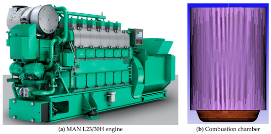
Figure 1.
The appearance of the MAN L23/30H engine and its combustion chamber.

Table 1.
The parameters of the MAN L23/30H diesel engine.
2.2. Simulation Model
In this study, the MAN L23/30H diesel engine was taken as the baseline for model modification, aiming to conduct numerical simulations of the injection and combustion processes of methanol and its pyrolysis gas. During the modification, the geometry and dimensions of the combustion chamber were kept unchanged. Due to the significant difference in lower heating values between methanol and diesel, more methanol needs to be supplied within the same time frame. Therefore, to avoid excessively increasing the injection pressure while keeping the number of injector holes constant, the injector orifice diameter was increased from 0.33 mm to 0.45 mm. The orifice diameter of the gas injector for pyrolysis gas was set at 0.4 mm. The methanol injector and the pyrolysis gas injector were symmetrically inclined, and their spatial positions are illustrated in Figure 2, where Figure 2a shows a front view and Figure 2b shows a top view. To ensure smooth ignition of methanol and its pyrolysis gas within the original engine structure, an ignition source with an energy of 0.2 J and a duration of 1.0 °CA was placed at the center, 2 mm away from the top surface of the combustion chamber.
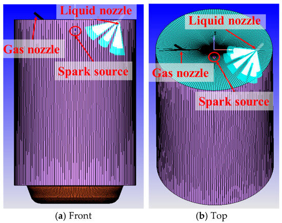
Figure 2.
Illustration of the position of methanol and its pyrolysis gas nozzles within the combustion chamber.
This study conducted numerical simulation research using Converge 3.0 software. In the process of numerical simulation, the principles of mass conservation, momentum conservation, and energy conservation are adhered to. The mass conservation equation is as follows:
where Um is the mass-averaged velocity, and ρm is the mixture density.
The momentum equation is as follows:
where F is the body force, μm is the viscosity of the mixture, and Udr,k is the drift velocity of phase k.
The energy equation is as follows:
where hj,k is the enthalpy of species j in phase k, Jj,k is the diffusive flux of species j in phase k, where Sh is the energy source term, keff is the thermal conductivity and Ek is described as:
For compressible flow, enthalpy h is a function of pressure and temperature, as follows:
where T is the temperature, cp is the specific heat under constant pressure. Using the volumetric thermal expansion (β), Equation (5) can be written as follows:
Table 2 presents the physical models employed in the simulation calculations. Turbulence was modeled by solving the unsteady Reynolds-Averaged Navier–Stokes (RANS) equations within the computational domain, with the k-ε RNG model [36] serving as the turbulence model. The RNG model, derived through the Renormalization Group (RNG) theory, bears similarities in form to the standard k-ε model but incorporates significant improvements. The RNG model introduces an additional term in its ε equation, enhancing the accuracy for rapidly strained flows, particularly in high-speed applications. Furthermore, the RNG model accounts for the influence of swirling flows on turbulence, thereby improving the precision of such flow patterns. While the standard k-ε model is tailored for high Reynolds number flows, RNG theory provides an analytically derived differential formula for effective viscosity that considers low Reynolds number effects, which is crucial for accurately capturing the flow characteristics in the near-wall region. The transport equations for turbulence kinetic energy (k) and dissipation rate (ε) are as follows:
where C2 = 1.9, Cε1 = 1.9, σk = 1.0, σε = 1.2, Gk is the turbulence kinetic energy generated by the velocity gradient of the laminar flow, Sk and Φε are user-defined source terms, and YM represents turbulence fluctuations generated by compressibility through expansion diffusion, expressed as follows:
where Mt is the turbulent Mach number.
Table 2.
Physical simulation models.
The KH-RT model [37], NTC model [38], and Frossling model [39] were utilized to simulate droplet breakup, collision, and evaporation processes, respectively. The O’Rourke and Amsden model [40] was applied to calculate wall heat flux. The chemical kinetics solver detailed by Sage et al. [41] was used to compute the chemical reaction rates within each grid cell. The methanol mechanism proposed by Li et al., which includes 21 species and 93 reactions, was adopted to simulate the combustion process of methanol and its pyrolysis gas. In particular, Li et al. [42] updated the detailed methanol mechanism proposed by Held and Dryer [43] based on rate constants and thermochemical data for OH, HO2, and CH2OH and validated its accuracy in terms of ignition delay time, laminar flame speed, and key species concentrations. The model predictions showed excellent agreement with the experimental measurements, indicating that the updated methanol mechanism is a comprehensive model for the combustion of CO, CH2O, and CH3OH and can be used to simulate the oxidation processes of methanol and DMG.
2.3. Boundary Conditions
In this paper, the Eulerian method is employed for the continuous injection of DMG gas through a gas nozzle located on the top surface of the combustion chamber, while the Lagrangian approach is utilized for the virtual injection of methanol in the liquid phase. The injection pulse width of the gas nozzle is controlled using the Events function in Converge. The DMG gas injection is driven by the pressure difference between the gas nozzle and the combustion chamber. Table 3 presents the initial boundary conditions for the combustion chamber and gas nozzle regions, and Table 4 outlines the injection strategies for methanol and DMG in different simulation cases. Across various cases, the initial in-cylinder pressure is manipulated to regulate the oxygen content in the cylinder air, thereby controlling the excess air coefficient within the cylinder.
Table 3.
Initial boundary conditions for the L23/30H engine.
Table 4.
Simulation conditions for different cases.
2.4. Mesh Study
Converge possesses highly efficient mesh generation and control techniques, enabling real-time automatic mesh generation during numerical simulations. In the mesh generation process, Converge employs surface nodes of the geometric model to create polyhedral meshes on the model’s boundaries while generating fully orthogonal hexahedral meshes within the interior of the geometric model. For mesh control, Converge primarily utilizes fixed refinement and adaptive refinement strategies to refine the mesh in regions with high velocity or temperature gradients or in geometrically complex areas. Consequently, the mesh study is divided into two primary components: first, determining an appropriate base mesh size; and second, applying adaptive and fixed refinements on the basis of the base mesh. Given that Converge does not allow direct and precise control over the number of mesh elements in the geometric model, this paper opts for a mesh independence verification approach based on varying base mesh sizes. The results of the basic mesh independence validation are shown in Figure 3. The peak pressure errors corresponding to different base grid sizes are presented in Table 5. As the mesh size decreased, the peak cylinder pressure gradually reduced. When the basic mesh size was smaller than 6.0 mm, the peak cylinder pressure gradually increased. This indicates that both excessively large and small mesh sizes can lead to deviations from the determined values. Notably, the results for the 7.0 mm and 6.0 mm mesh sizes almost overlapped, suggesting that these two sizes did not introduce significant errors in the simulation results. However, for the computer with 72 threads utilized in this study, the computational time required to complete the simulation with a grid size of 6.0 mm was approximately 2.7 h, whereas the time needed for the model with a grid size of 7.0 mm was about 1.7 h, representing an hour reduction in computational time. To ensure computational accuracy while maintaining efficiency, a larger mesh size was chosen for model discretization. Therefore, 7.0 mm was selected as the basic mesh size.

Figure 3.
Mesh independence verification. (a) The cylinder pressure curves obtained under various base meshes. (b) The corresponding number of mesh elements for each base mesh. (c) The peak cylinder pressure values achieved with different base meshes. (d) The computational time required for simulating different meshes (excluding the combustion process).
Table 5.
Peak pressure errors for different base grid sizes.
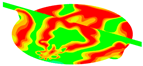
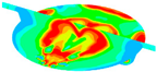
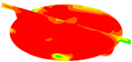
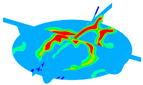
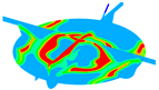
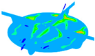
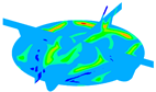
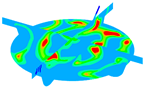
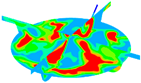
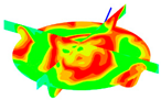
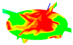
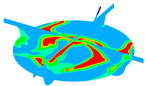
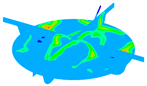
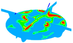
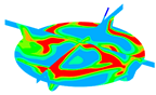
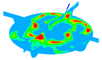
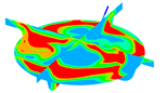
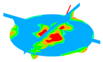
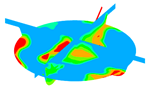
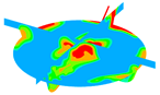
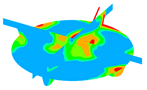
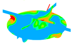
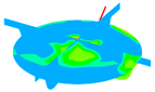
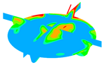
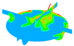
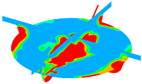
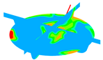
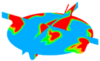
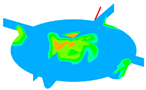
Converge software possesses an adaptive mesh refinement capability, which allows for the use of a larger base mesh to accelerate computational efficiency during the simulation process. Personalized refinement is applied in regions with significant velocity and temperature gradients to enhance computational accuracy. In this study, automatic refinement with a level of 2 was triggered when the velocity gradient exceeded 0.1 m/s. Similarly, a temperature gradient greater than 2.5 K also prompted automatic refinement at level 2. Additionally, to better simulate the droplet breakup and evaporation processes, a fixed refinement with a level of 3 was implemented along the path of the liquid fuel spray. Figure 4 presents a comparison of the in-cylinder temperature distribution at the top dead center (TDC) with and without grid refinement strategies. It is evident that grid refinement enables the capture of more detailed simulation features.
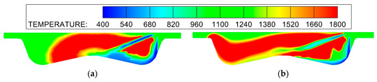
Figure 4.
Comparison of in-cylinder temperature distribution (at Top Dead Center) with and without grid refinement strategies. (a) Without Grid Refinement. (b) With Grid Refinement.
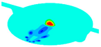
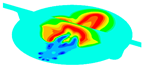
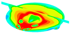
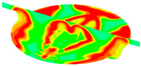
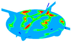
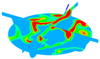
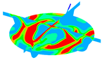
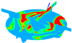
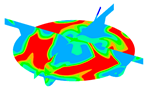
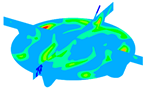
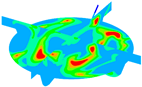
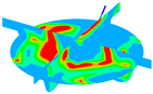
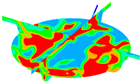
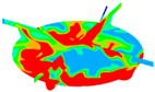
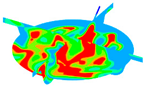
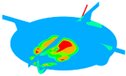
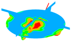
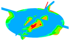
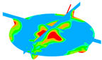
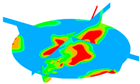
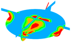
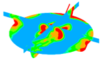
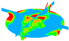
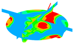
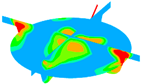
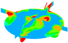
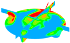
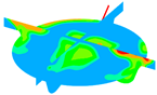
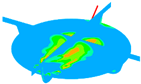
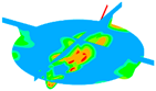
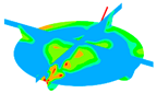
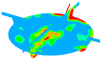
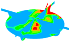
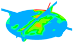
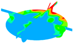
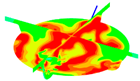
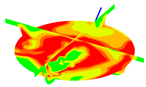
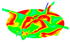
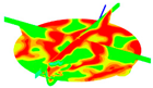
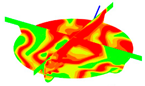
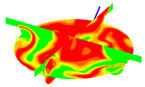
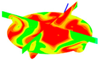
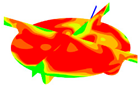
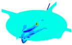
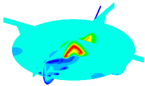
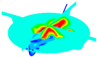
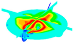
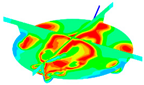
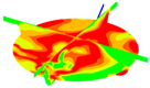
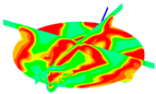
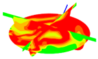
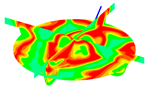
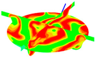
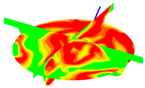
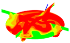
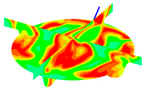
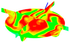
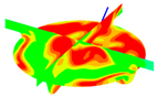
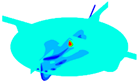
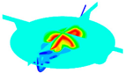
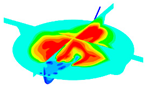
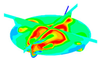
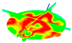
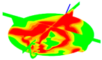
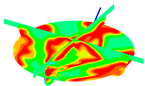
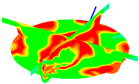
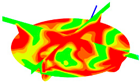
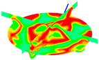
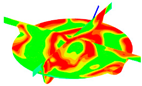
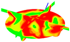
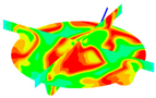
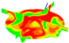
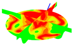
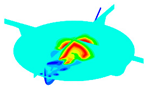
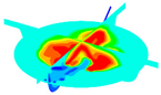
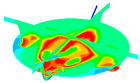
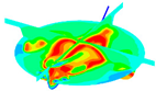
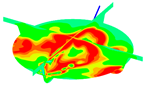
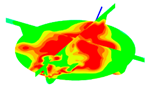
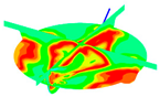
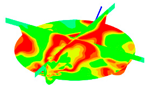
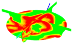
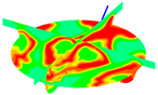
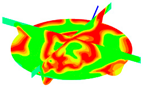
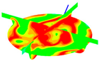
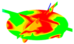
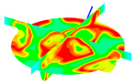
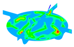
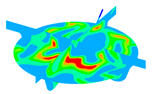
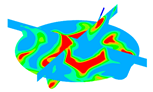
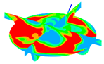
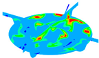
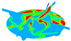
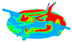
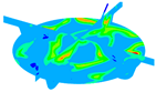
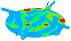
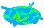
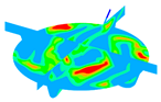
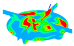
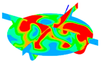
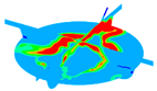
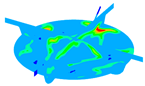
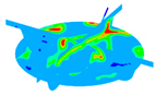
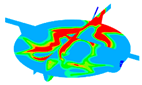
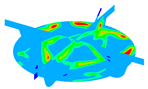
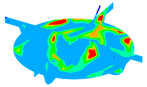
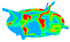
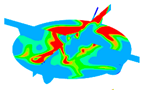
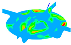
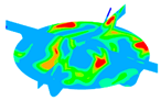
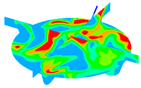
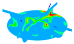
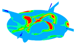
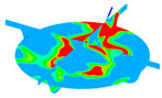
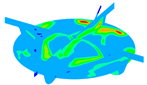
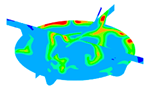
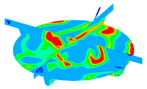
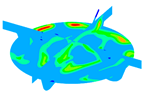
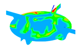
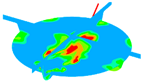
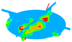
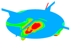
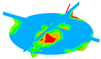
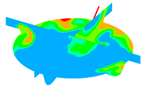
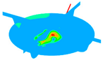
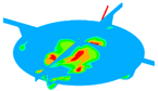
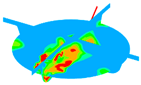
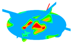
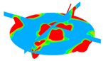
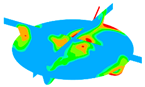
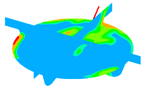
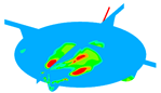
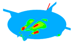
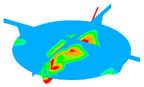
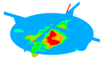
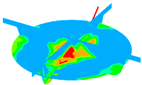
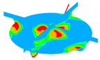
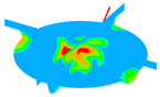
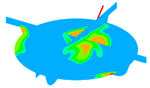
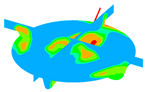
Figure 5 illustrates the mesh division during gas injection, liquid injection, and combustion processes within the combustion chamber. The colors in the figure represent velocity magnitudes, with redder colors indicating higher velocities at that location. At −146.0 °CA, the gas injector is operating, and, due to the velocity gradient, the pyrolysis gas injection path is automatically refined. At −12 °CA, the liquid fuel spray path is also refined due to the velocity gradient. By 50 °CA, combustion is nearly complete, and refinement near the cylinder wall is observed due to temperature gradients. After refinement, the maximum number of hexahedral mesh elements during the numerical simulation was 1,772,252, while the minimum was 20,178. Through independent verification of the base mesh and the refinement of the mesh, the simulation model can achieve more accurate and efficient computations during numerical simulations. Following the mesh study, we believe that the base mesh and refinement strategy employed in this paper are reliable and can be utilized for subsequent research endeavors.
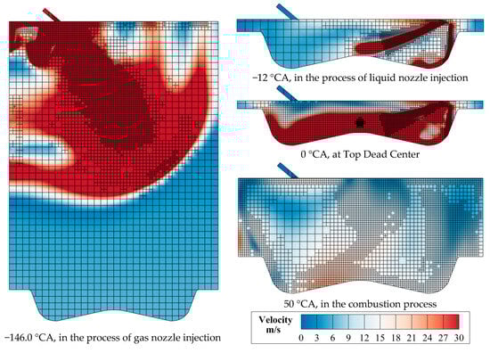
Figure 5.
Mesh division at different time points (color map represents velocity).
2.5. Model Validation
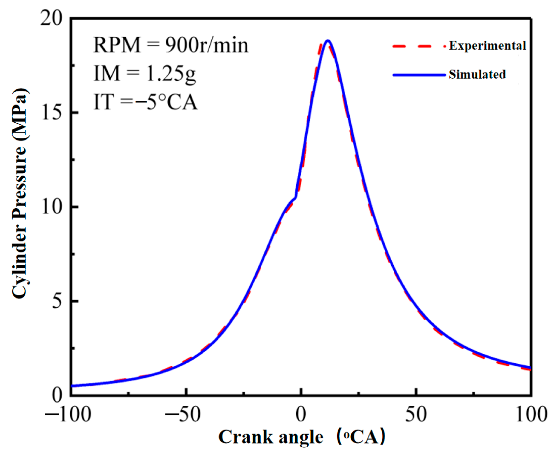
After conducting mesh independence verification and implementing automatic mesh refinement, the computational process was ensured to proceed smoothly in terms of model geometry. However, the reliability of simulation models such as the droplet breakup model, turbulence model, and combustion model still needs to be validated. Achieving the supply of DMG and methanol within the same cycle poses challenges for the integration of the methanol pyrolysis, gas supply, and liquid supply systems. Considering the experimental constraints, the validation process in this study was based on experimental results obtained from the original engine operating in pure diesel mode. It was observed that, under conditions of an engine speed of 900 r/min, an injection mass of 1.25 g, and an injection timing of −5 °CA, there was a small error between the experimental and simulated values. Additionally, the simulated cylinder pressure rise time aligned well with the experimental rise time, indicating that the Sage combustion model can accurately capture the ignition and mixture combustion timing observed in the experiments. As the only differences between this simulation model and the one established in this study are the fuel type and fuel injection location, the detailed methanol mechanism used in this study can ensure the accuracy of methanol and its pyrolysis gas during ignition and combustion processes, and so the accuracy of the engine model for methanol and its pyrolysis gas established in this study is sufficient for its use in subsequent simulation studies. Comparison of the experimental and simulated values is shown in Figure 6.
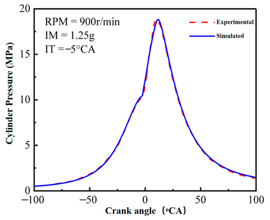
Figure 6.
Comparison of the experimental and simulated values.
3. Results and Discussion
3.1. The Effect of DMG Blending on In-Cylinder Pressure During Stoichiometric Combustion
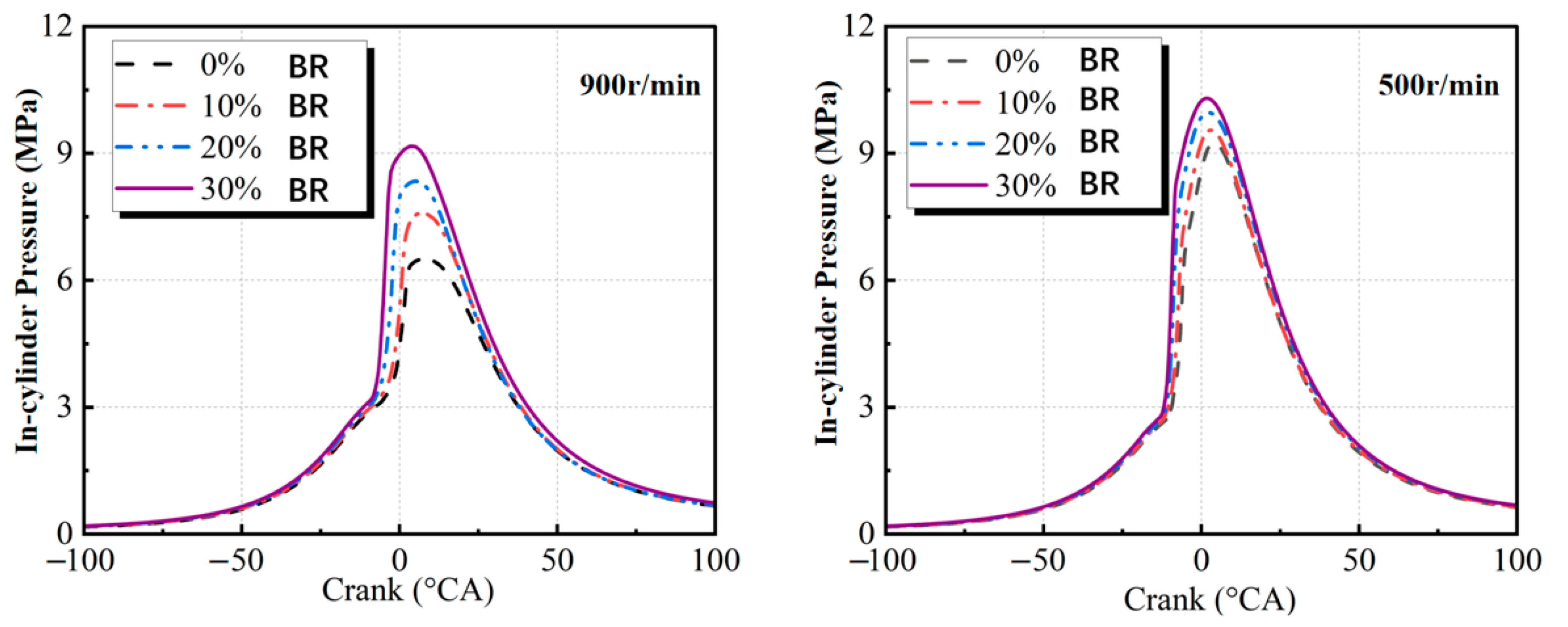
Figure 7 illustrates the effect of DMG blending on in-cylinder pressure during stoichiometric combustion. The incorporation of DMG led to an increase in the peak in-cylinder pressure and advanced the crank angle at which this peak occurred. At an engine speed of 900 rpm, the peak in-cylinder pressure without DMG blending was 6.5 MPa, occurring at a crank angle of 8.01° ATDC (after the top dead center). With the addition of DMG, increasing the blending ratio raised the peak in-cylinder pressure to 7.59 MPa, 8.34 MPa, and 9.17 MPa, with corresponding crank angles advancing to 9.31° ATDC, 11.01° ATDC, and 12.62° ATDC, respectively. This indicates that the incorporation of DMG significantly enhanced the combustion process’s speed and efficiency.
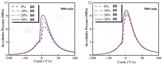
Figure 7.
Influence of various blending ratios on in-cylinder pressure.
At a lower speed of 500 rpm, without DMG blending, the maximum in-cylinder pressure was 9.24 MPa, occurring at 4.04 °CA ATDC. As the DMG blending ratio increased to 10%, 20%, and 30%, the peak in-cylinder pressure rose to 9.54 MPa, 9.94 MPa, and 10.24 MPa, respectively, with corresponding crank angles advancing to 5.04° ATDC, 5.84° ATDC, and 6.34° ATDC. This change is primarily attributed to the promotion of fuel combustion within the cylinder by the blended DMG, which accelerates the pressure rise rate, leading to increased peak in-cylinder pressure and an earlier occurrence of this peak. The incorporation of DMG not only accelerates the combustion velocity but also enhances the isochoric combustion degree and the work efficiency of the expansion process. This is due to the fact that the main components of DMG, CO, and H2 exhibit higher reactivity than methanol and have shorter ignition delay periods. Consequently, blending DMG into methanol fuel significantly reduces the ignition delay time of the mixture. Additionally, the enhanced reactivity of the fuel leads to more complete combustion, resulting in a significant increase in in-cylinder pressure and temperature. However, it also increases the mechanical load, friction losses, and heat transfer losses of the engine, leading to an elevated thermal load.
3.2. The Effect of DMG Addition on Heat Release Rate During Stoichiometric Combustion
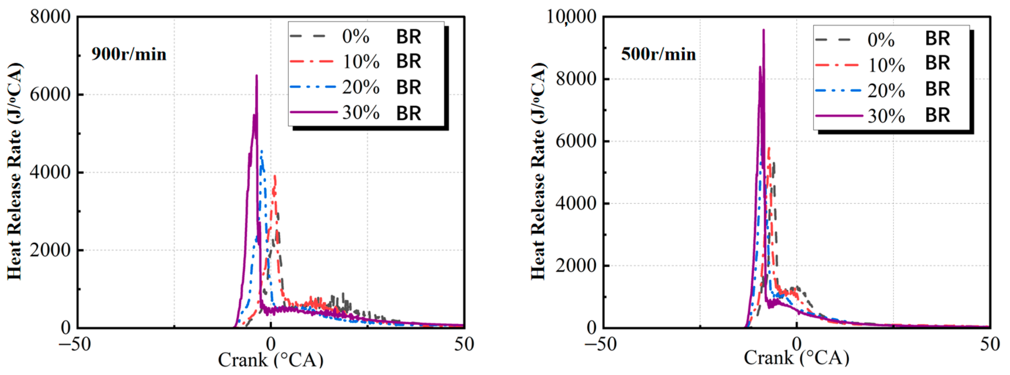
Figure 8 illustrates the effect of DMG incorporation on the heat release rate during stoichiometric combustion. The addition of DMG increased the peak heat release rate and caused the peak to occur earlier. This shift advanced the heat release to the earlier stages of combustion and reduced the crank angle duration of the concentrated heat release process. Combustion characteristic parameters are shown in Table 6.
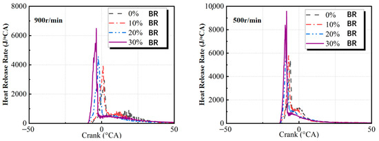
Figure 8.
Impact of different blending ratios on the heat release rate.
Table 6.
Combustion characteristic parameters during stoichiometric combustion.
The primary cause of these effects is the high hydrogen content in DMG. Hydrogen’s high combustion speed enhances the fuel burning rate within the cylinder, increasing the peak heat release rate and advancing its occurrence. Excessively early combustion, however, can increase compression negative work and reduce expansion work. To optimize combustion efficiency and engine performance in practical applications, adjusting the ignition advance angle may be necessary. Such adjustment aims to control the timing of the heat release process, reduce compression negative work, increase expansion work, and ensure the majority of heat release occurs during the expansion stroke. This approach ultimately improves the engine’s overall work efficiency.
Table 7 and Table 8 summarize the effects of different blending ratios on combustion characteristic parameters. As shown in the tables, DMG incorporation significantly shortened the ignition delay and rapid combustion periods (advancing CA10 and CA90), thereby accelerating the fuel burning rate and concentrating the heat release process.
Table 7.
Combustion characteristic parameters at a rotational speed of 900 r/min.
Table 8.
Combustion characteristic parameters at a rotational speed of 500 r/min.
3.3. The Effect of In-Cylinder Mean Temperature During Stoichiometric Combustion
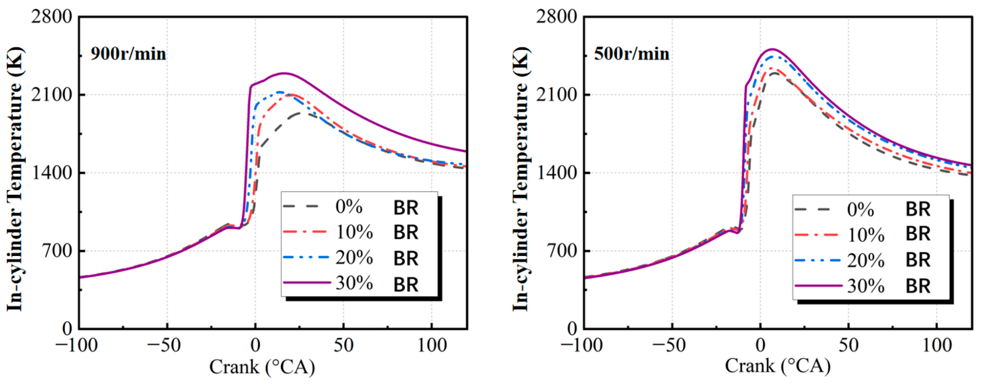
Figure 9 depicts the effect of DMG addition on the in-cylinder mean temperature at two engine speeds. The incorporation of DMG significantly increased the peak in-cylinder temperature and advanced its occurrence. This result indicates that DMG addition accelerated the combustion process within the cylinder, raised the peak combustion temperature, and caused an earlier crank angle for this peak. An increase in the DMG blending ratio elevated the thermal load within the cylinder and increased heat transfer losses. Additionally, the extended duration of high-temperature conditions within the cylinder created favorable conditions for NOx formation.
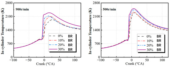
Figure 9.
The influence of different blending ratios on in-cylinder temperature.
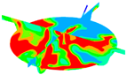
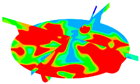
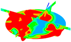
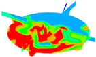
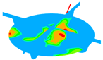
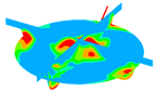
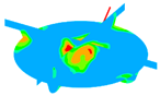
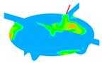
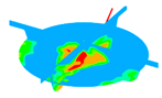
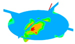
Table 9 and Table 10 illustrate the in-cylinder temperature contours at various blending ratios. The addition of DMG expanded the high-temperature region, increased its diffusion rate, and significantly enhanced both the flame propagation speed and range.
Table 9.
Temperature contour plots for the same cross-sectional plane under different blending ratios at a speed of 900 r/min.
Table 10.
Temperature contour plots for the same cross-sectional plane under different blending ratios at a speed of 500 r/min.
3.4. The Influence on Emissions During Stoichiometric Combustion
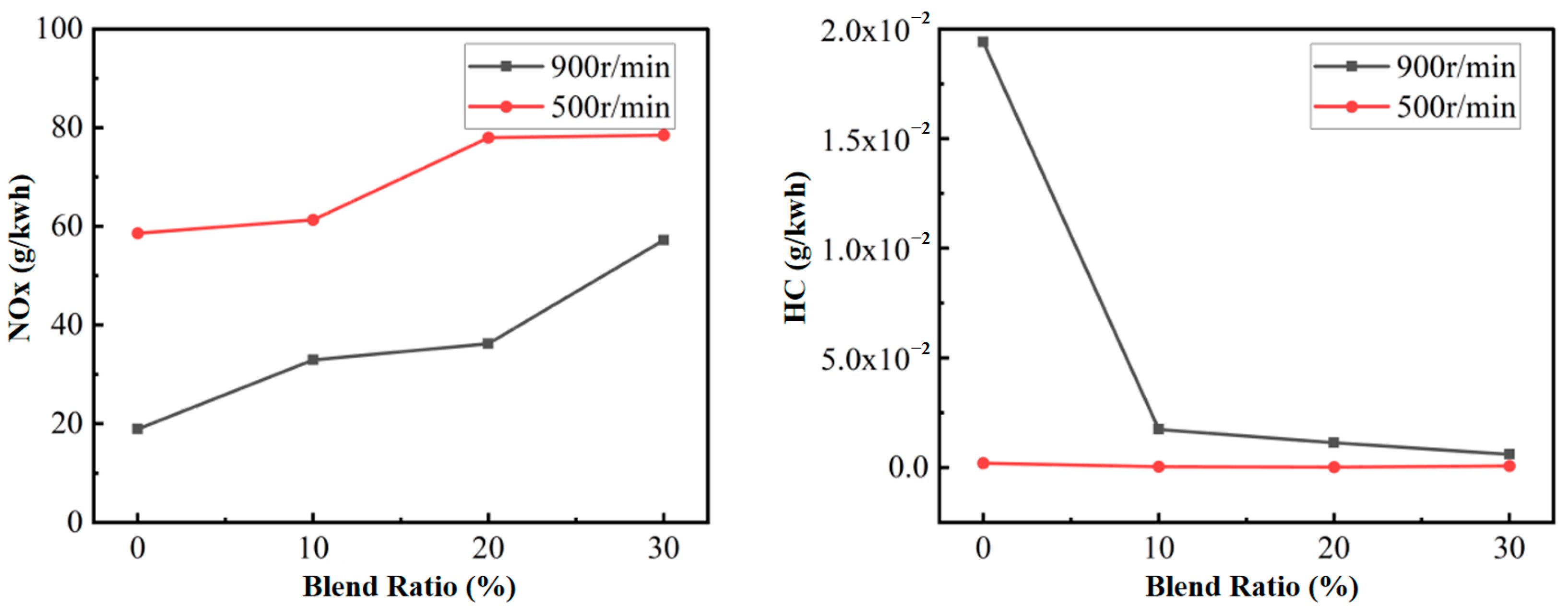
Figure 10 illustrates the effects of varying DMG blending ratios on NOx and HC emissions at engine speeds of 900 r/min and 500 r/min. The observed increase in NOx emissions was primarily attributed to elevated in-cylinder temperatures and an extended crank angle interval favorable for NOx formation. At the lower engine speed of 500 r/min, NOx emissions were significantly higher than those at 900 r/min due to the prolonged exposure to high temperatures.
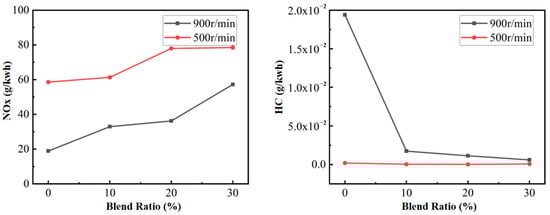
Figure 10.
Effect of various DMG blending ratios on NOx and HC emissions.
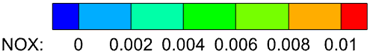
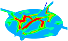
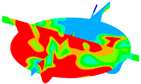
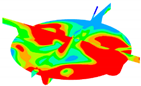
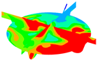
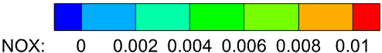
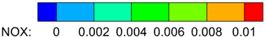
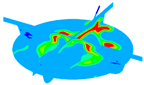
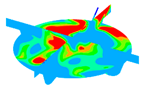
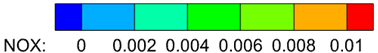
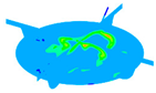
Table 11 and Table 12 depict NOx contour maps for various blending ratios. The incorporation of DMG expanded the NOx formation region primarily due to increased in-cylinder temperatures and extended high-temperature duration, which intensified NOx production.
Table 11.
NOx emission contour plots for the same cross-sectional interface under different blending ratios at a speed of 900 r/min.
Table 12.
NOx emission contour plots for the same cross-sectional interface under different blending ratios at a speed of 500 r/min.
At 500 r/min, DMG blending resulted in nearly negligible HC emissions. This reduction is attributed to the longer duration available for complete combustion at lower engine speeds, improving combustion efficiency. The rapid combustion of hydrogen accelerates the overall combustion process during DMG blending, increasing in-cylinder temperatures and promoting the complete combustion of methanol, thereby reducing HC emissions. Furthermore, the short quenching distance of DMG mitigates the quenching effect, further lowering HC emissions.
As the DMG blending ratio increased, CO emissions decreased significantly, whereas CO2 emissions showed a slight increase. Soot emissions were also notably reduced at both engine speeds. These changes are primarily attributed to the high hydrogen content of DMG, which accelerates combustion and promotes complete fuel oxidation, reducing CO and soot emissions while slightly increasing CO2 emissions.
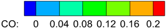
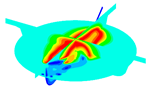
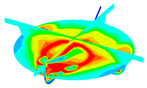
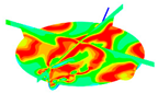
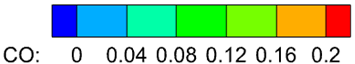
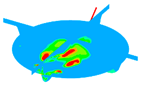
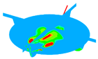
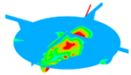
Table 13 and Table 14 illustrate CO emission contour maps for the same conditions. The tables reveal that, although DMG blending initially increased CO concentrations, CO was rapidly consumed during combustion, especially at higher blending ratios. As a result, DMG incorporation effectively reduced CO emissions.
Table 13.
CO emission contour plots for the same cross-sectional interface under different blending ratios at a speed of 900 r/min.
Table 14.
CO emission contour plots for the same cross-sectional interface under different blending ratios at a speed of 500 r/min.
3.5. The Influence of DMG Injection on In-Cylinder Pressure During Lean Combustion
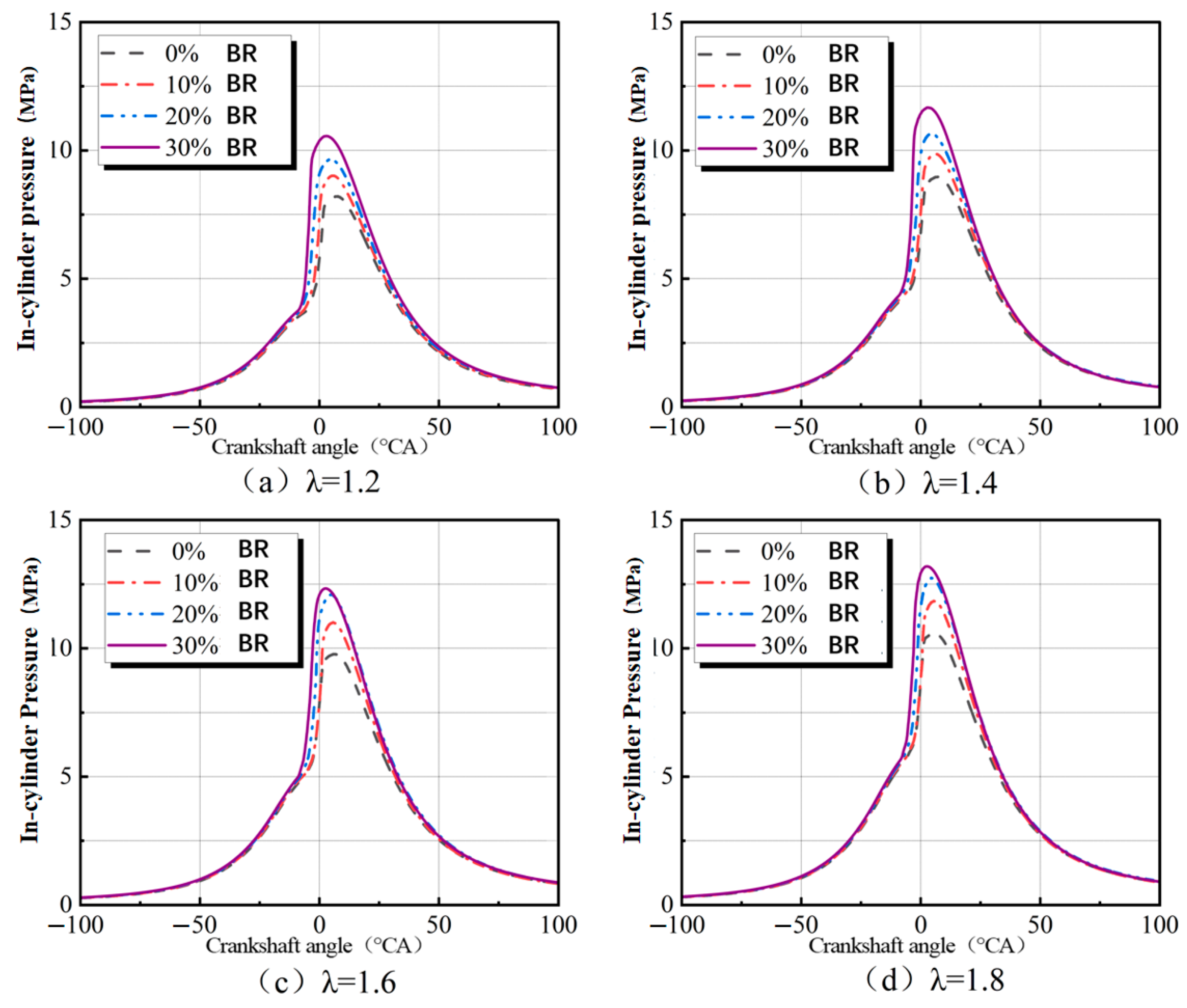
Figure 11 depicts the impact of varying DMG blending ratios on in-cylinder pressure during lean combustion conditions. Without DMG blending, increasing the excess air ratio led to a rise in peak in-cylinder pressure from 8.2 MPa to 10.5 MPa while the corresponding crank angle advanced from 7.6 °CA BTDC to 5.7 °CA BTDC. This observation suggests that higher excess air ratios increase peak in-cylinder pressure in the absence of DMG blending. This increase is primarily due to elevated intake pressure, which enhances the pressure rise during compression, increases air intake, and provides sufficient oxygen for complete fuel combustion.
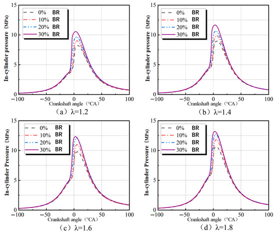
Figure 11.
The influence of different blending ratios on the in-cylinder average pressure.
At an excess air ratio (λ) of 1.2, DMG blending ratios of 10%, 20%, and 30% increased peak in-cylinder pressures to 9 MPa, 9.6 MPa, and 10.5 MPa, respectively, with crank angles advancing to 5.7 °CA BTDC, 4.6 °CA BTDC, and 2.8 °CA BTDC. Relative to the non-blended condition, DMG blending increased peak in-cylinder pressures by 0.8 MPa, 1.4 MPa, and 2.3 MPa, with crank angle advancements of 1.9 °CA, 3 °CA, and 4.8 °CA, respectively. At λ = 1.4, DMG blending exhibited similar effects on in-cylinder pressure and crank angle advancement as observed at λ = 1.2, with more pronounced improvements at higher blending ratios.
At higher excess air ratios (λ = 1.6 and 1.8), blending 30% DMG had minimal impact on peak in-cylinder pressure. This limitation arises because higher excess air ratios produce leaner mixtures, inhibiting stable and rapid flame propagation. Even with DMG addition, its effect on flame stability and propagation speed remains constrained.
3.6. The Influence of DMG Injection on Heat Release Rate During Lean Combustion
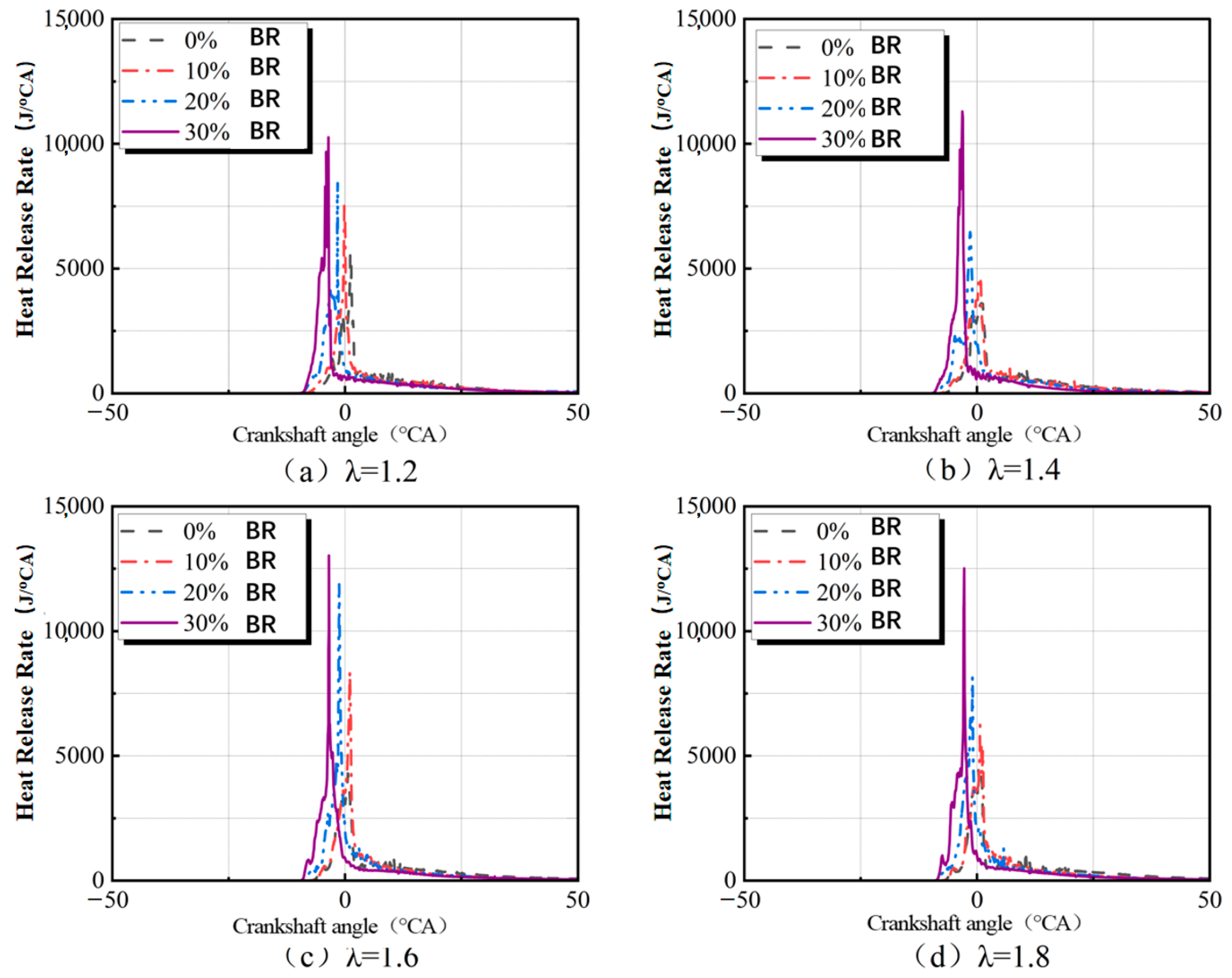
Figure 12 illustrates the effects of varying DMG blending ratios on the heat release rate during lean-burn conditions. The results demonstrate that, at a constant excess air ratio, increasing the DMG blending ratio elevates the peak heat release rate and shortens the crank angle duration of the main heat release phase, leading to more concentrated heat release. This effect is primarily due to the high combustion speed of hydrogen in DMG, which extends the lean-burn limit and facilitates in-cylinder combustion closer to isochoric (constant-volume) conditions. Combustion characteristic parameters under various excess air ratios (λ) are shown in Table 15.
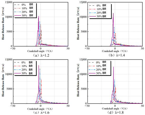
Figure 12.
Impact of different blending ratios on heat release rate during lean-burn conditions.
Table 15.
Combustion characteristic parameters under various excess air ratios (λ).
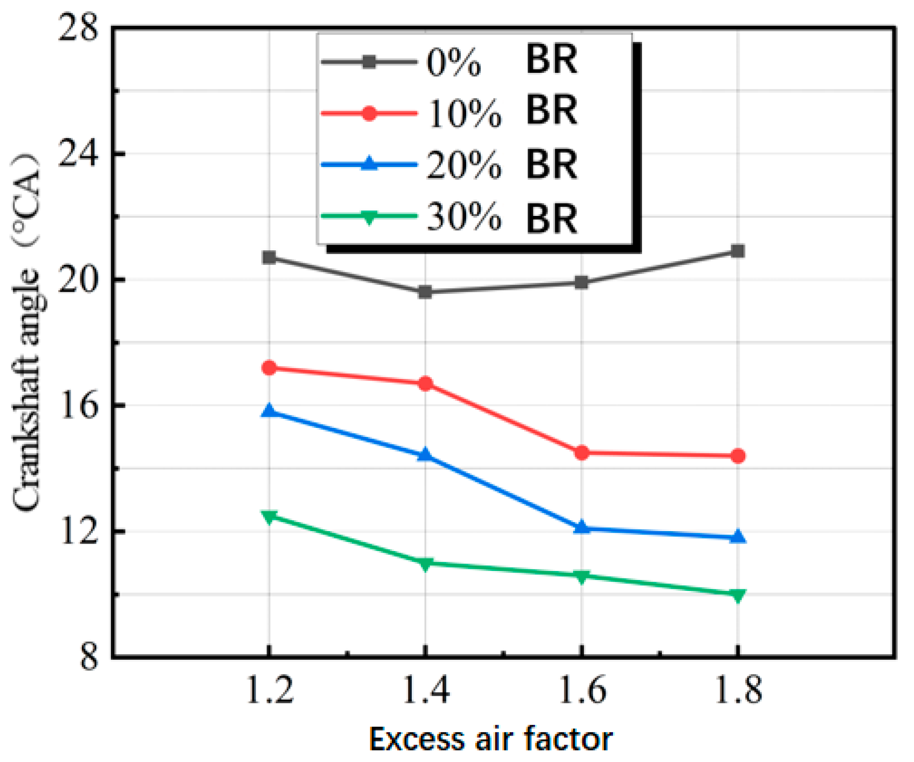
Table 16, Table 17, Table 18 and Table 19 summarize the effects of different DMG blending ratios on combustion characteristic parameters during lean-burn conditions. The tables indicate that, at a constant excess air ratio, DMG blending reduces both the ignition delay period and the rapid combustion phase, with CA10 and CA90 occurring earlier. This suggests that DMG accelerates the in-cylinder combustion process, leading to more concentrated heat release.
Table 16.
Combustion characteristic parameters at an excess air ratio (λ) of 1.2.
Table 17.
Combustion characteristic parameters at an excess air ratio (λ) of 1.4.
Table 18.
Combustion characteristic parameters at an excess air ratio (λ) of 1.6.
Table 19.
Combustion characteristic parameters at an excess air ratio (λ) of 1.8.
Therefore, it can be inferred that DMG blending enhances the combustion process by reducing both the ignition delay and the duration of the rapid combustion phase at a given excess air ratio. At a constant blending ratio, the interplay between DMG’s combustion-promoting effects and the combustion-inhibiting effects of higher excess air ratios resulted in irregular patterns of ignition delay and rapid combustion phase durations as the excess air ratio increased.
3.7. The Impact of DMG Injection on In-Cylinder Average Temperature During Lean Combustion
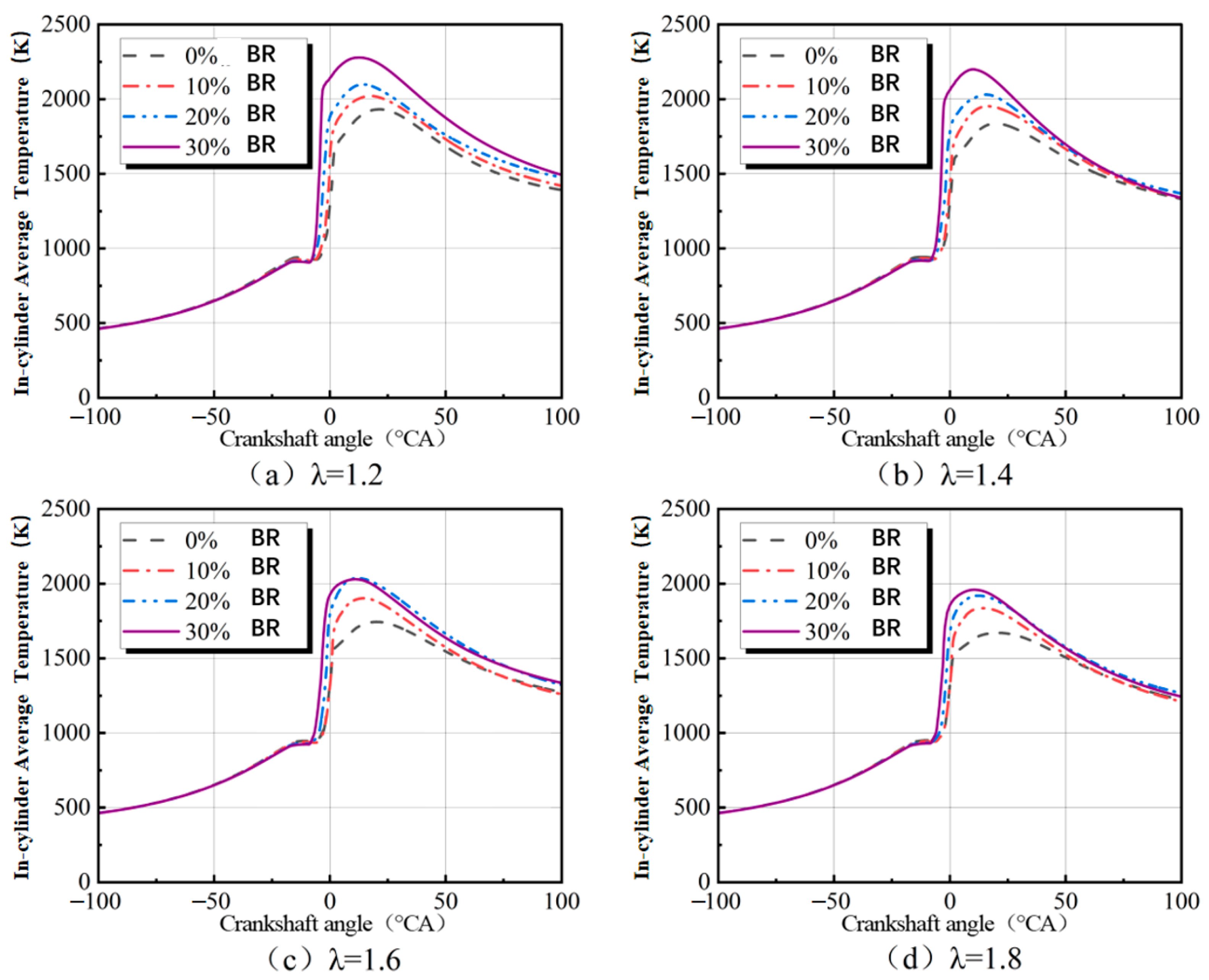
Figure 13 illustrates the impact of varying DMG blending ratios on in-cylinder temperature under lean-burn conditions. In the absence of DMG blending, the peak in-cylinder temperatures for excess air ratios (λ) of 1.2, 1.4, 1.6, and 1.8 were 1931 K, 1836 K, 1744 K, and 1671 K, respectively. The corresponding crank angles for these peak temperatures occurred at 20.7 °CA ATDC, 19.6 °CA ATDC, 19.9 °CA ATDC, and 20.9 °CA ATDC, respectively. Thus, in the absence of DMG blending, the peak in-cylinder temperature decreased as the excess air ratio increased, while the corresponding crank angle initially advanced and then retarded.
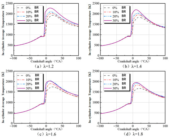
Figure 13.
The influence of different blending ratios on in-cylinder average temperature.
This phenomenon is primarily attributed to the increased air intake at higher excess air ratios. Excess air absorbs heat released during combustion, thereby reducing the peak in-cylinder temperature as the excess air ratio increases. A moderate increase in the excess air ratio ensures more uniform air–fuel mixture distribution within the cylinder, reducing locally rich zones and promoting stable, efficient combustion, which slightly increases the combustion rate. At excessively high excess air ratios, the cylinder mixture becomes excessively lean, resulting in deteriorated combustion and slower flame propagation. As a result, the crank angle corresponding to the peak in-cylinder temperature initially advanced and then retarded.
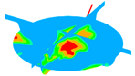
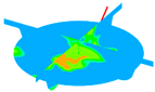
Table 20, Table 21, Table 22 and Table 23 present cylinder temperature contours under lean-burn conditions, demonstrating that DMG incorporation expanded the high-temperature region and significantly accelerated its diffusion. The data indicate that increasing the DMG blending ratio notably expanded the high-temperature zone in the same cross-section. These findings suggest that DMG blending accelerates fuel combustion and enhances the heat release rate, thereby improving combustion efficiency.
Table 20.
Temperature contour plots for the same cross-sectional plane under different blending ratios when λ = 1.2.
Table 21.
Temperature contour plots for the same cross-sectional plane under different blending ratios when λ = 1.4.
Table 22.
Temperature contour plots for the same cross-sectional plane under different blending ratios when λ = 1.6.
Table 23.
Temperature contour plots for the same cross-sectional plane under different blending ratios when λ = 1.8.
Figure 14 illustrates the effects of various DMG blending ratios on the crank angle corresponding to the peak in-cylinder temperature during lean-burn conditions. Without DMG blending, the crank angle corresponding to the peak in-cylinder temperature initially advanced and subsequently retarded as the excess air ratio increased. When DMG was blended at ratios of 10%, 20%, or 30%, the crank angle corresponding to the peak in-cylinder temperature advanced continuously with increasing excess air ratio.
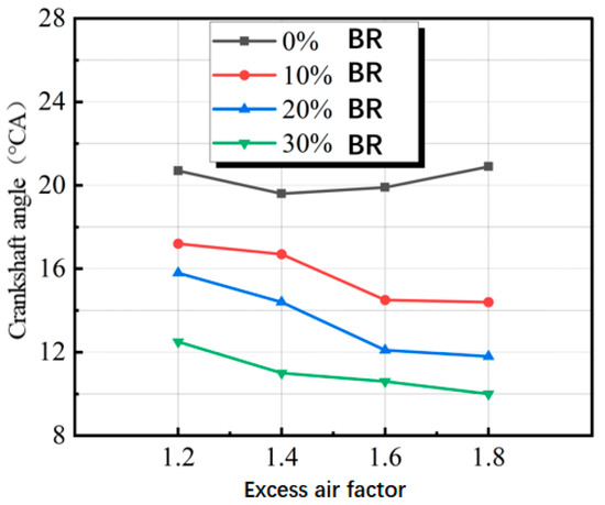
Figure 14.
The influence of lean combustion on the crank angle corresponding to the peak in-cylinder temperature.
This phenomenon can be explained as follows: Without DMG blending, a moderate increase in the excess air ratio promotes a more uniform air–fuel mixture distribution within the cylinder, reducing local rich zones and fostering stable and efficient combustion, thereby slightly increasing the combustion rate. At excessively high excess air ratios, however, the cylinder mixture becomes overly lean, leading to deteriorated combustion and slower flame propagation. Consequently, increasing the excess air ratio initially advances and subsequently retards the crank angle corresponding to the peak in-cylinder temperature.
In contrast, when DMG is blended, the crank angle corresponding to the peak in-cylinder temperature consistently advances with increasing excess air ratio. This is primarily because DMG blending significantly accelerates the combustion rate, with its positive effects outweighing the inhibitory impact of higher excess air ratios.
3.8. The Impact of DMG Blending on Emissions During Lean Combustion
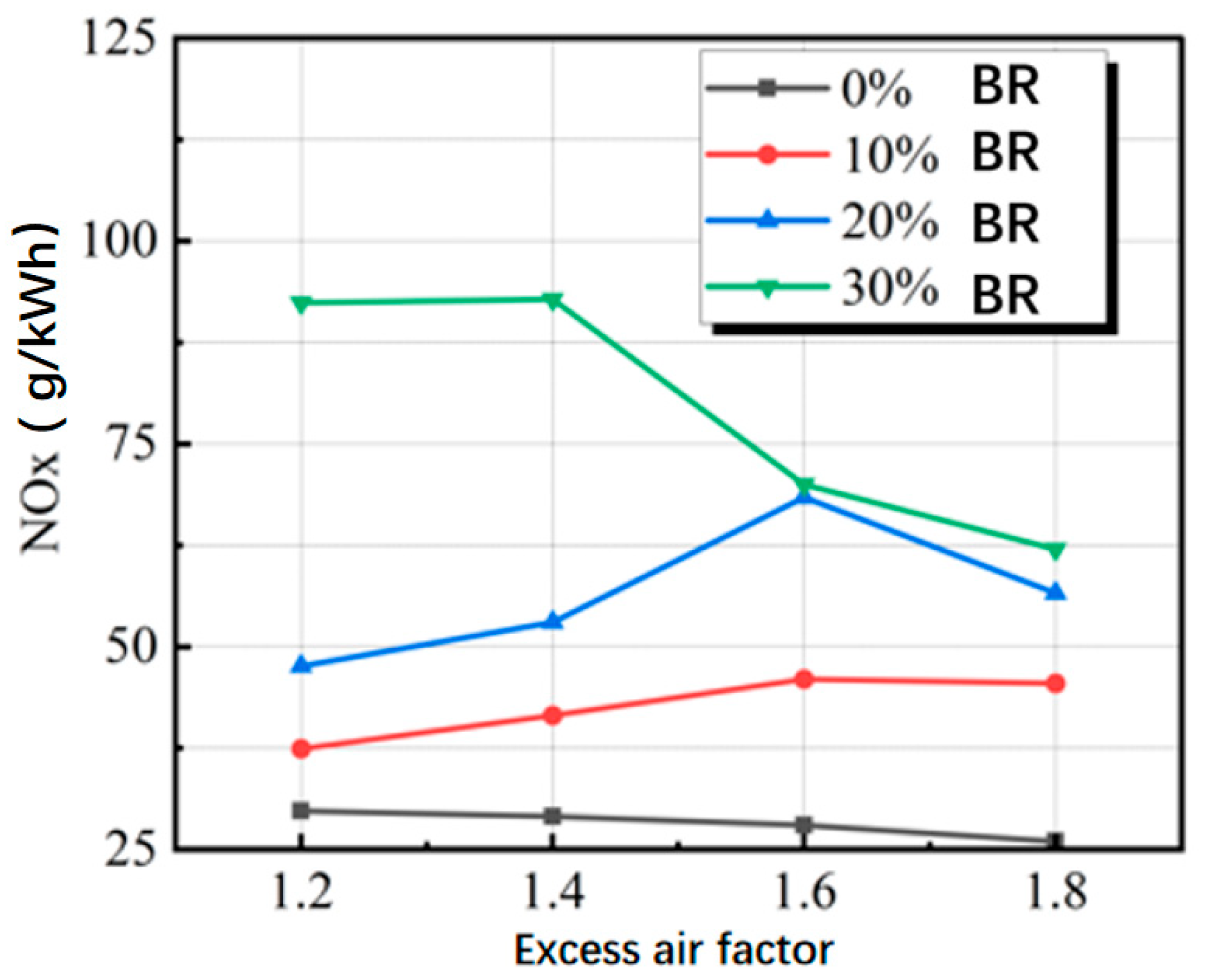
Figure 15 demonstrates the effects of varying DMG blending ratios on NOx emissions under lean-burn conditions in internal combustion engines. At a fixed excess air ratio, increasing the DMG blending ratio results in a proportional rise in NOx emissions. This phenomenon is primarily attributed to the high hydrogen content of DMG, which burns rapidly and enhances fuel combustion in the cylinder, thereby raising the average in-cylinder temperature as the blending ratio increases. Since elevated temperatures are a key factor in NOx formation, DMG incorporation significantly increases NOx emissions. NOx emissions gradually decrease when the excess air coefficient exceeds 1.6. This reduction is due to the more uniform air–fuel mixture distribution at higher excess air coefficients, which minimizes locally fuel-rich zones, the primary sites for NOx formation. With fewer localized high-temperature zones during combustion, NOx production is significantly reduced.

Figure 15.
Effect of different excess air coefficients on engine NOx emissions.
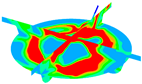
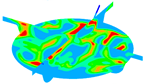
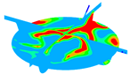
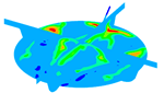
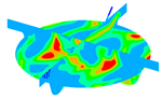
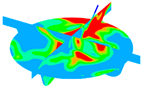
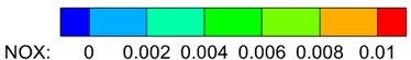
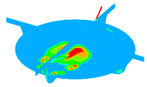
Table 24, Table 25, Table 26 and Table 27 illustrate NOx distribution contours for varying excess air ratios. The tables show that increasing the DMG blending ratio enlarges the NOx generation region within the cylinder, resulting in higher emissions. Conversely, at a fixed blending ratio, higher excess air ratios reduce the NOx generation region and emissions in the cylinder. This occurs because excess air absorbs more heat, reducing the average in-cylinder temperature and suppressing NOx formation. Thus, DMG blending significantly impacts in-cylinder temperature and chemical reactions, thereby influencing emission composition. To address NOx emissions effectively, comprehensive consideration of DMG blending and excess air ratio adjustments is essential for optimizing engine emissions performance.
Table 24.
NOx emission contour plots for the same cross-sectional interface under different blending ratios when λ = 1.2.
Table 25.
NOx emission contour plots for the same cross-sectional interface under different blending ratios when λ = 1.4.
Table 26.
NOx emission contour plots for the same cross-sectional interface under different blending ratios when λ = 1.6.
Table 27.
NOx emission contour plots for the same cross-sectional interface under different blending ratios when λ = 1.8.
In pure methanol combustion mode, NOx emissions decrease as the excess air ratio increases. This reduction is primarily attributed to the dilution of the in-cylinder mixture, which lowers flame propagation speed and reduces combustion efficiency. Furthermore, the additional air absorbs heat, lowering the average in-cylinder temperature and thereby reducing NOx generation and emissions. For blending ratios of 10% or 20% DMG, an initial increase in NOx emissions was observed with increasing excess air ratio, followed by a subsequent decrease. This trend arises from a moderate increase in the excess air ratio (from 1.2 to 1.6), during which excess air absorbs heat from fuel combustion, resulting in a temperature decrease and combustion deterioration. However, this effect was accompanied by an extended high-temperature duration within the cylinder, which contributed to NOx formation.
At higher excess air ratios (1.6 to 1.8), the reduced combustion temperature under lean-burn conditions became the dominant factor in lowering NOx emissions. Despite DMG blending, NOx emissions decreased due to the reduction in combustion temperature. For a blending ratio of 30% DMG, the elevated combustion temperature caused by the high blending ratio and lower excess air ratio resulted in significantly higher NOx emissions compared to other conditions. As the cylinder transitioned to lean-burn conditions, NOx emissions gradually declined. NOx (g/(kWh)) emissions under different blending ratios and λ values are shown in Table 28.
Table 28.
NOx (g/(kWh)) emissions under different blending ratios and λ values.
Figure 16 illustrates the effects of lean combustion on hydrocarbon (HC) emissions. At blending ratios of 20% and 30% DMG, HC emissions were nearly negligible, corresponding to a 99% reduction compared to pure methanol combustion. This reduction is primarily attributed to the increased in-cylinder combustion temperature associated with DMG blending, which enhances fuel combustion completeness and minimizes HC formation.
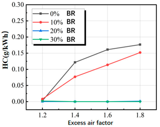
Figure 16.
The influence of lean combustion on HC emissions.
Additionally, in cases without DMG blending or with a 10% blending ratio, increasing the excess air ratio resulted in higher HC emissions. This increase is attributed to the higher excess air ratio, which, while introducing more air into the cylinder, simultaneously slows combustion and lowers the temperature, exacerbating the quenching effect and thereby promoting HC formation. HC (g/(kWh)) emissions under different blending ratios and λ values are shown in Table 29.
Table 29.
HC (g/(kWh)) emissions under different blending ratios and λ values.
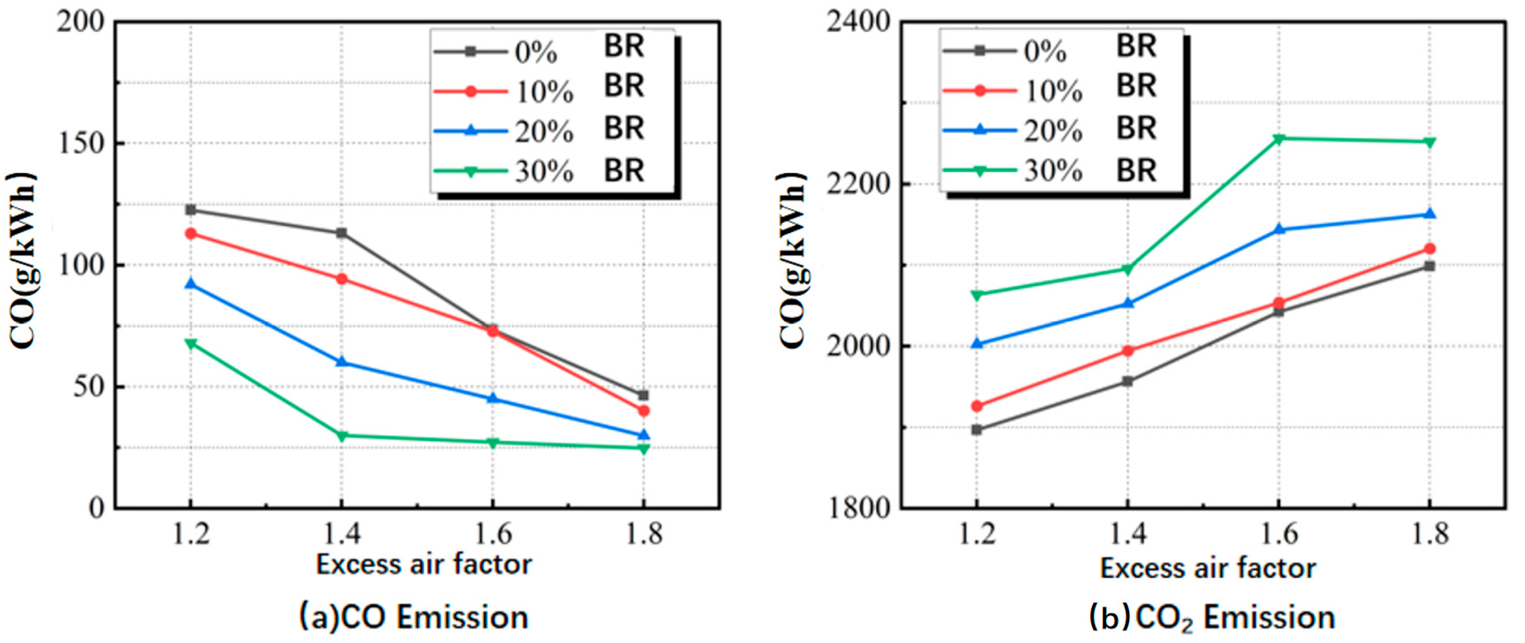
Figure 17 presents the impact of lean combustion on CO and CO2 emissions. At a constant blending ratio of DMG, the engine’s CO emissions decreased as the excess air ratio increased, whereas CO2 emissions exhibited a corresponding increase. This phenomenon can be attributed to the production of CO, which results from incomplete fuel combustion. As the excess air ratio increases, additional air enters the cylinder, supplying more oxidants for fuel combustion, thereby promoting more complete combustion and the formation of CO2. Furthermore, blending DMG fosters more complete fuel combustion. An increase in the excess air ratio enhances the fuel-air mixing quality, leading to a more uniform distribution of the mixture and reducing locally fuel-rich regions, which in turn minimizes CO production due to incomplete combustion. Consequently, as the excess air ratio increased, the engine’s CO emissions decreased, while CO2 emissions increased. CO and CO2 (g/(kWh)) emissions under different blending ratios and λ values are shown in Table 30 and Table 31.
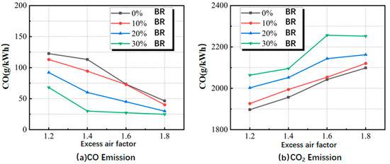
Figure 17.
The impact of excess air ratio on CO and carbon dioxide emissions.
Table 30.
CO (g/(kWh)) emissions under different blending ratios and λ values.
Table 31.
CO2 (g/(kWh)) emissions under different blending ratios and λ values.
Table 32, Table 33, Table 34 and Table 35 present CO emission contour plots corresponding to various excess air ratios at a constant cross-section. The tables show that, although an increase in the DMG blending ratio initially raised CO concentration, the CO consumption rate accelerated as the combustion process advanced, particularly at higher blending ratios. This suggests that blending DMG improves combustion efficiency and accelerates CO conversion, thereby effectively reducing the engine’s CO emissions.
Table 32.
CO emission contour plots for the same cross-sectional interface under different blending ratios when λ = 1.2.
Table 33.
CO emission contour plots for the same cross-sectional interface under different blending ratios when λ = 1.4.
Table 34.
CO emission contour plots for the same cross-sectional interface under different blending ratios when λ = 1.6.
Table 35.
CO emission contour plots for the same cross-sectional interface under different blending ratios when λ = 1.8.
3.9. The Impact of DMG Blending on Indicated Thermal Efficiency During Lean Combustion
When the engine indicated thermal efficiency was studied, it was divided into two categories: comprehensive indicated thermal efficiency and fuel indicated thermal efficiency . Fuel-indicated thermal efficiency takes into account the heat absorbed during the decomposition of methanol into DMG, while comprehensive indicated thermal efficiency ignores this heat. The calculation formulas for the comprehensive indicated thermal efficiency , and fuel indicated thermal efficiency are as follows:
where denotes the indicated work per cycle, denotes the amount of heat applied to the cylinder per cycle, and denotes the heat absorbed by the exhaust gas for methanol cracking to produce methanol cracking gas.
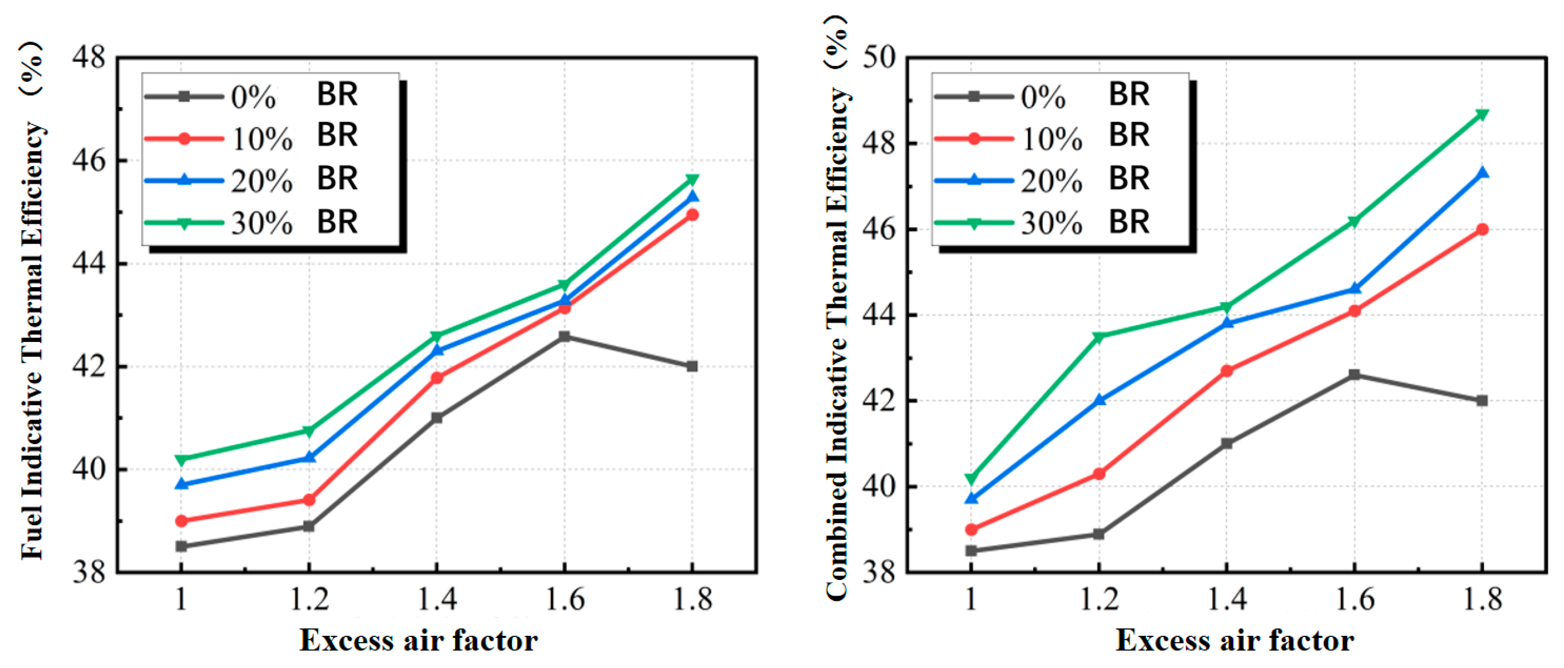
Figure 18 illustrates the influence of the excess air ratio on the engine’s indicated thermal efficiency. In the absence of DMG blending, the fuel’s indicated thermal efficiency was equivalent to the overall indicated thermal efficiency. Both efficiencies initially increased, followed by a decrease as the excess air ratio rose. Specifically, as the excess air ratio increased from 1 to 1.6, the indicated thermal efficiency rose from 38.5% to 42.6%; however, when the ratio increased further to 1.8, the efficiency slightly decreased to 42%. This is due to the excessively high excess air coefficient, which results in a significantly higher proportion of oxygen in the mixture. This, in turn, leads to longer ignition delays, extended main combustion durations, a reduced heat release rate, and increased cyclic combustion variability. However, when compared to an excess air coefficient of 1.6, both the fuel-indicated thermal efficiency and the combustion-indicated thermal efficiency decrease by less than 1% at an excess air coefficient of 1.8. Considering the previously discussed NOx emission characteristics, we recommend maximizing the DMC blending ratio. To mitigate the adverse impact of excessively high DMG proportions on engine emissions, a higher excess air coefficient should be utilized.
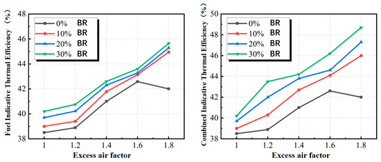
Figure 18.
The impact of different excess air ratios on fuel indicated thermal efficiency and combined indicated thermal efficiency.
When 10% DMG was blended, both indicated thermal efficiencies improved across all air ratios. This improvement became more pronounced as the blending ratio increased to 20% and 30%, with the overall indicated thermal efficiency peaking at 48.7%. This enhancement is primarily attributed to the hydrogen content in the DMG, which facilitates more complete combustion of the fuel within the cylinder. The hydrogen effect is particularly pronounced at higher air ratios, resulting in improved thermal efficiency.
4. Conclusions
This study utilized the L23/30H four-stroke diesel engine as the subject of investigation. By integrating the methanol combustion reaction mechanism, a simulation model was developed in which a gas injector was installed on the cylinder head to facilitate the direct injection of DMG into the cylinder. Using CONVERGE simulation software, the impact of DMG blending on the performance and emissions of a direct-injection methanol engine was analyzed under stoichiometric combustion conditions at rated and idle speeds, as well as under lean combustion conditions at rated speed. The primary findings are as follows:
(1) Under stoichiometric combustion conditions at both rated and idle speeds, the incorporation of DMG increased the peak cylinder pressure, peak heat release rate, and peak in-cylinder temperature while advancing the timing of these occurrences. Specifically, as the DMG blending ratio increases from 0% to 30%, the peak pressure in the combustion chamber rises from 6.5 MPa to 9.17 MPa. The blended mixture containing DMG also exhibited a faster combustion rate, characterized by notable ignition delay and rapid combustion phases, resulting in an earlier center of heat release. Furthermore, the blending of DMG significantly reduces emissions of unburned hydrocarbons (HC), carbon monoxide (CO), and soot, particularly at low speeds (500 RPM), where HC emissions are nearly zero. This phenomenon is attributed to the high combustion speed of hydrogen in DMG, which facilitates a more complete combustion process. Although combustion with DMG blending effectively reduces other pollutants, NOx emissions increase. This is primarily due to the rise in combustion chamber temperature and the prolongation of high-temperature duration, indicating that balancing the control of various emissions is crucial for optimizing the combustion process.
(2) Under lean-burn conditions, the blended combustion of DMG and methanol significantly enhances the fuel’s indicated thermal efficiency. When the excess air ratio (λ) is 1.8 and the DMG blending ratio is 30%, the fuel’s indicated thermal efficiency reaches its peak. This suggests that the introduction of DMG facilitates more complete combustion. As the DMG blending ratio increases, both the peak in-cylinder pressure and heat release rate significantly increase under lean-burn conditions. The high combustion speed of DMG accelerates the combustion process, concentrating the heat release and reducing combustion delay. The blending of DMG results in an increase in in-cylinder temperature, accompanied by a noticeable expansion of high-temperature regions. This rise in temperature enhances combustion stability and efficiency. However, under conditions of a high excess air ratio and high blending ratio, limitations in mixture concentration and hydrogen combustion speed within the cylinder prevented the incorporation of DMG from significantly enhancing peak pressure and heat release rate.
(3) Increasing the excess air ratio led to a decrease in NOx emissions, an increase in hydrocarbon emissions, and a reduction in CO emissions. Under lean-burn conditions, while DMG blending enhances combustion efficiency, the increase in in-cylinder temperature leads to a significant rise in NOx emissions. This is because high-temperature environments promote the formation of NOx, particularly at high DMG blending ratios. Simultaneously, the introduction of DMG significantly reduces HC and CO emissions. This is primarily due to the high reactivity of hydrogen in DMG, which facilitates more complete combustion and reduces the formation of locally fuel-rich zones, thereby lowering HC and CO emissions.
To translate the laboratory results of this study into practical applications, we propose the following steps for validating our findings. First, conduct field testing. Evaluate the methanol engine in real-world conditions to verify the impact of DMG blending on performance and emissions. This should include evaluating engine performance under various operating conditions and monitoring emission levels under actual marine conditions. Second, collect and analyze data from the long-term operation of the methanol engine to assess the impact of DMG blending on engine durability and maintenance needs. Finally, assess the long-term environmental impact of DMG blending, including the potential benefits of reduced emissions on air quality and climate change. We acknowledge that scaling these laboratory findings to practical applications may present challenges, including operational costs, technical feasibility, and regulatory constraints. Therefore, we emphasize the need for further research to address these challenges and optimize the implementation of DMG blending in real-world marine engines.
Author Contributions
X.L.: Writing—review and editing, Methodology, Funding acquisition. J.Z.: Software, Data curation. Z.W. (Zhongcheng Wang): Writing—original draft, Investigation. Z.W. (Zihan Wang): Writing—review and editing. Z.Z.: Software, Data curation. W.W.: Visualization, Validation. H.C.: Visualization, Validation. All authors have read and agreed to the published version of the manuscript.
Funding
This research was supported by the National Key R&D Program of China (Grant No. 2022YFB4300701, December 2022–November 2026) and the National Key R&D Program of China (Grant No. 2022YFB4300704, December 2022–November 2026).
Institutional Review Board Statement
Not applicable.
Informed Consent Statement
Not applicable.
Data Availability Statement
Data is contained within the article.
Conflicts of Interest
Authors Wenhua Wang and Haiping Cai were employed by the company Shanghai Ocean Shipping Co., Ltd. The remaining authors declare that the research was conducted in the absence of any commercial or financial relationships that could be construed as a potential conflict of interest.
References
- International Maritime Organization. 2023 IMO Strategy on Reduction of GHG Emissions from Ships. July 2023. Available online: https://www.imo.org/en/OurWork/Environment/Pages/2023-IMO-Strategy-on-Reduction-of-GHG-Emissions-from-Ships.aspx (accessed on 29 November 2024).
- International Energy Agency. Global Energy Review: CO2 Emissions in 2020. March 2021. Available online: https://www.iea.org/articles/global-energy-review-co2-emissions-in-2020 (accessed on 29 November 2024).
- Wang, C.; Liu, H.; Zhang, M.; Zhong, X.; Wang, H.; Jin, C.; Yao, M. Experimental and kinetic modeling studies on oxidation of methanol and di-tert-butyl peroxide in a jet-stirred reactor. Combust. Flame 2023, 258, 113093. [Google Scholar] [CrossRef]
- Hayri, Y.; Kadir, M.Y.; Raja Mazuir, R.S.A.; Hakan, S.S. Effects of compression ratio on thermodynamic and sustainability parameters of a diesel engine fueled with methanol/diesel fuel blends containing 1-pentanol as a co-solvent. Fuel 2024, 357, 129929. [Google Scholar]
- Ji, C.; El Halwagi, M.M. A data-driven study of IMO compliant fuel emissions with consideration of black carbon aerosols. Ocean Eng. 2020, 218, 108241. [Google Scholar] [CrossRef]
- Liu, J.; Yang, J.; Sun, P.; Gao, W.; Yang, C.; Fang, J. Compound combustion and pollutant emissions characteristics of a common-rail engine with ethanol homogeneous charge and polyoxymethylene dimethyl ethers injection. Appl. Energy 2019, 239, 1154–1162. [Google Scholar] [CrossRef]
- Methanol Institute. Methanol Price and Supply/Demand. 2023. Available online: https://www.methanol.org/methanol-price-supply-demand/ (accessed on 16 December 2024).
- Zincir, B.; Deniz, C.; Tunér, M. Investigation of environmental, operational and economic performance of methanol partially premixed combustion at slow speed operation of a marine engine. J. Clean. Prod. 2019, 235, 1006–1019. [Google Scholar] [CrossRef]
- Chen, H.; Su, X.; He, J.; Xie, B. Investigation on combustion and emission characteristics of a common rail diesel engine fueled with diesel/n-pentanol/methanol blends. Energy 2019, 167, 297–311. [Google Scholar] [CrossRef]
- Hoang, A.T.; Foley, A.M.; Nižetić, S.; Huang, Z.; Ong, H.C.; Ölçer, A.I.; Pham, V.V.; Nguyen, X.P. Energy-related approach for reduction of CO2 emissions: A critical strategy on the port-to-ship pathway. J. Clean. Prod. 2022, 355, 131772. [Google Scholar] [CrossRef]
- Liu, J.; Liu, Y.; Ji, Q.; Sun, P.; Wang, T.; Wang, P. Theoretical and experimental investigation of physicochemical properties and combustion performance of PODE/methanol blends. Fuel 2023, 334, 126668. [Google Scholar] [CrossRef]
- Cui, Y.; Liu, H.; Wen, M.; Feng, L.; Wang, C.; Ming, Z.; Zhang, Z.; Zheng, Z.; Zhao, H.; Wang, X.; et al. Optical diagnostics and chemical kinetic analysis on the dual-fuel combustion of methanol and high reactivity fuels. Fuel 2022, 312, 122949. [Google Scholar] [CrossRef]
- Duraisamy, G.; Rangasamy, M.; Govindan, N. A comparative study on methanol/diesel and methanol/PODE dual fuel RCCI combustion in an automotive diesel engine. Renew. Energy 2020, 145, 542–556. [Google Scholar] [CrossRef]
- Chen, Z.; Zhao, P.; Zhang, H.; Chen, H.; He, H.; Wu, J.; Wang, L.; Lou, H. An optical study on the cross-spray characteristics and combustion flames of automobile engine fueled with diesel/methanol under various injection timings. Energy 2024, 290, 130286. [Google Scholar] [CrossRef]
- Cung, K.D.; Wallace, J.; Kalaskar, V.; Smith, E.M., III; Briggs, T.; Bitsis, D.C., Jr. Experimental study on engine and emissions performance of renewable diesel methanol dual fuel (RMDF) combustion. Fuel 2024, 357, 129664. [Google Scholar] [CrossRef]
- Wang, X.; Liu, Y.; Han, L.; Gong, Y.; Ma, H.; Qian, D.; Liu, M.; Xie, F. Influence of blending dissociated methanol gas and optimizing dilution working fluid on improving performance of methanol engine. Int. J. Hydrogen Energy 2024, 91, 1442–1451. [Google Scholar]
- Wang, X.; Liu, Y.; Jiang, B.; Jin, Z.; Su, Y.; Xie, F. Analysis of the effect of the coupling application of dissociated methanol gas and methanol direct double injection on the engine dilution combustion performance by the Taguchi method. Int. J. Hydrogen Energy 2024, 94, 1453–1463. [Google Scholar]
- Li, B.; Zhong, F.; Wang, R.; Jiang, Y.; Chen, Y. Experimental and numerical study on a SI engine fueled with gasohol and dissociated methanol gas blends at lean conditions. Energy 2024, 292, 130540. [Google Scholar] [CrossRef]
- Fu, J.; Deng, B.; Liu, J.; Wang, L.; Xu, Z.; Yang, J.; Shu, G. Study of SI engine fueled with methanol vapor and dissociation gas based on exhaust heat dissociating methanol. Energy Convers. Manag. 2014, 79, 213–223. [Google Scholar] [CrossRef]
- Panda, K.; Ramesh, A. Diesel injection strategies for reducing emissions and enhancing the performance of a methanol based dual fuel stationary engine. Fuel 2021, 289, 119809. [Google Scholar] [CrossRef]
- Tian, Z.; Wang, Y.; Zhen, X.; Liu, Z. The effect of methanol production and application in internal combustion engines on emissions in the context of carbon neutrality: A review. Fuel 2022, 320, 123902. [Google Scholar] [CrossRef]
- Valera, H.; Kumar, D.; Agarwal, A.K. Evaluating the effect of variable methanol injection timings in a novel co-axial fuel injection system equipped locomotive engine. J. Cleaner Prod. 2022, 349, 131452. [Google Scholar] [CrossRef]
- Kumar, D.; Sonawane, U.; Chandra, K.; Agarwal, A.K. Experimental investigations of methanol fumigation via port fuel injection in preheated intake air in a single cylinder dual-fuel diesel engine. Fuel 2022, 324, 124340. [Google Scholar] [CrossRef]
- Zhou, F.; Yu, J.; Wu, C.; Fu, J.; Liu, J.; Duan, X. The application prospect and challenge of the alternative methanol fuel in the internal combustion engine. Sci. Total Environ. 2024, 913, 169708. [Google Scholar] [CrossRef] [PubMed]
- Jamrozik, A. The effect of the alcohol content in the fuel mixture on the performance and emissions of a direct injection diesel engine fueled with diesel methanol and diesel-ethanol blends. Energy Convers. Manag. 2017, 148, 461–476. [Google Scholar] [CrossRef]
- Gong, C.; Yi, L.; Zhang, Z.; Sun, J.; Liu, F. Assessment of ultra-lean burn characteristics for a stratified-charge direct-injection spark-ignition methanol engine under different high compression ratios. Appl. Energy 2020, 261, 114478. [Google Scholar] [CrossRef]
- Zhou, Y.; Hong, W.; Xie, F.; Li, X.; Su, Y.; Hu, Y.; Wang, W. Potential of compression ratio and exhaust gas dilution on improving combustion and nitrogen oxides emission performance on a PFI engine fueled with methanol. Fuel 2022, 323, 124197. [Google Scholar] [CrossRef]
- Chen, C.; Yao, A.; Yao, C.; Wang, B.; Lu, H.; Feng, J.; Feng, L. Study of the characteristics of PM and the correlation of soot and smoke opacity on the diesel methanol dual fuel engine. Appl. Therm. Eng. 2019, 148, 391–403. [Google Scholar] [CrossRef]
- Li, Y.; Chen, H.; Zhang, C.; Chen, H. Effects of diesel pre-injection on the combustion and emission characteristics of a common-rail diesel engine fueled with diesel methanol dual-fuel. Fuel 2021, 290, 119824. [Google Scholar] [CrossRef]
- Li, Z.; Wang, Y.; Yin, Z.; Gao, Z.; Wang, Y.; Zhen, X. Parametric study of a single-channel diesel/methanol dual-fuel injector on a diesel engine fueled with directly injected methanol and pilot diesel. Fuel 2021, 302, 121156. [Google Scholar] [CrossRef]
- Wang, Y.; Wang, H.; Meng, X.; Tian, J.; Wang, Y.; Long, W.; Li, S. Combustion characteristics of high pressure direct-injected methanol ignited by diesel in a constant volume combustion chamber. Fuel 2019, 254, 115598. [Google Scholar] [CrossRef]
- Ning, L.; Duan, Q.; Kou, H.; Zeng, K. Parametric study on effects of methanol injection timing and methanol substitution percentage on combustion and emissions of methanol/diesel dual-fuel direct injection engine at full load. Fuel 2020, 279, 118424. [Google Scholar] [CrossRef]
- Li, Y.; Jia, M.; Xu, L.; Bai, X.-S. Multiple-objective optimization of methanol/diesel dual-fuel engine at low loads: A comparison of reactivity controlled compression ignition (RCCI) and direct dual fuel stratification (DDFS) strategies. Fuel 2020, 262, 116673. [Google Scholar] [CrossRef]
- Yin, X.; Li, W.; Duan, H.; Duan, Q.; Kou, H.; Wang, Y.; Yang, B.; Zeng, K. A comparative study on operating range and combustion characteristics of methanol/diesel dual direct injection engine with different methanol injection timings. Fuel 2023, 334, 126646. [Google Scholar] [CrossRef]
- Li, Z.Y.; Wang, Y.; Yin, Z.B.; Geng, H.; Zhu, R.; Zhen, X. Effect of injection strategy on a diesel/methanol dual-fuel direct-injection engine. Appl. Therm. Eng. 2021, 189, 116691. [Google Scholar] [CrossRef]
- Yakhot, V.; Orszag, S.A. Renormalization group analysis of turbulence. I. Basic theory. J. Sci. Comput. 1986, 1, 3–51. [Google Scholar] [CrossRef]
- Reitz, R.D. Mechanism of breakup of round liquid jets. Encycl. Fluid Mech. 1986, 10. Available online: https://cir.nii.ac.jp/crid/1571135650050758016#citations_container (accessed on 29 November 2024).
- Schmidt, D.P.; Rutland, C.J. A new droplet collision algorithm. J. Comput. Phys. 2000, 164, 62–80. [Google Scholar] [CrossRef]
- Amsden, A. KIVA-II: A Computer Program for Chemically Reactive Flows with Sprays; Los Alamos National Laboratory Report LA-11560-MS; Los Alamos National Laboratory (LANL): Los Alamos, NM, USA, 1989. [Google Scholar]
- Amsden, A. KIVA-3V: A Block-Structured KIVA Program for Engines with Vertical or Canted Valves; Los Alamos National Laboratory (LANL): Los Alamos, NM, USA, 1997. [Google Scholar]
- Senecal, P.K.; Pomraning, E.; Richards, K.J.; Briggs, T.E.; Choi, C.Y.; Mcdavid, R.M.; Patterson, M.A. Multi-dimensional modeling of direct-injection diesel spray liquid length and flame lift-off length using CFD and parallel detailed chemistry. SAE Trans. 2003, 112, 1331–1351. [Google Scholar]
- Li, J.; Zhao, Z.; Kazakov, A.; Chaos, M.; Dryer, F.L.; Scire, J.J. A comprehensive kinetic mechanism for CO, CH2O, and CH3OH combustion. Int. J. Chem. Kinet. 2007, 39, 109–136. [Google Scholar] [CrossRef]
- Held, T.J.; Dryer, F.L. A comprehensive mechanism for methanol oxidation. Int. J. Chem. Kinet. 1998, 30, 805–830. [Google Scholar] [CrossRef]


Disclaimer/Publisher’s Note: The statements, opinions and data contained in all publications are solely those of the individual author(s) and contributor(s) and not of MDPI and/or the editor(s). MDPI and/or the editor(s) disclaim responsibility for any injury to people or property resulting from any ideas, methods, instructions or products referred to in the content. |
© 2024 by the authors. Licensee MDPI, Basel, Switzerland. This article is an open access article distributed under the terms and conditions of the Creative Commons Attribution (CC BY) license (https://creativecommons.org/licenses/by/4.0/).