Abstract
Gravel packing in deep-water horizontal wells is an effective and practical sand control method, which is a key technical method to ensure efficient exploitation of deep-water oil and gas. To ensure the successful implementation of gravel packing in deep water horizontal wells, it is crucial to carry out effective optimization design of packing parameters. This paper proposes a novel optimization design approach for gravel packing in deep-water horizontal wells. In the proposed approach, an optimization model is proposed for gravel packing in deep-water horizontal wells, in which the gravel packing length is regarded as the objective function. Then, an improved artificial electric field algorithm (IAEFA) is introduced for optimizing the key gravel packing parameters so as to determine the maximum gravel packing length. For a specific case study, we conducted optimization calculations for gravel packing in a deep-water horizontal well. Results of the case study demonstrate that the optimization design approach based on the IAEFA algorithm can effectively address the parameter optimization problem of deep-water horizontal well gravel packing. For the target well of the case study, the maximum packing length obtained by the IAEFA algorithm could reach 1000.22 m, and the corresponding 3 sets of optimal packing parameters were also obtained. In the scenario of optimal packing parameters, the total time of gravel packing in target well is 566.6 min, and the total amount of sand consumption is 54,050.94 lbs. The bottom hole pressure during the injection stage remains stable with about 9780 psi, then slowly rises from 9788 psi to 9837 psi in the α-wave packing stage, and rapidly increases from 9837 psi to 9986 psi in the β-wave packing stage. The proposed approach provides an efficient and practical optimization tool for the optimal design of gravel packing in deep water horizontal wells.
1. Introduction
The horizontal well, as an economically efficient method, has been wildly applied for the exploitation of offshore natural gas. However, the loose sandstone reservoir structure of offshore natural gas is highly susceptible to damage during the exploitation process, resulting in the detachment of formation sand and flowing into the wellbore along with high-speed gas flow, thereby affecting the normal production and exploitation of horizontal wells. Therefore, one of the key challenges in the horizontal well exploitation of offshore natural gas is how to effectively prevent formation sand from entering the wellbore. The horizontal well gravel packing, as an efficient and practical sand control method, has been wildly applied in the actual development of horizontal wells. In the specific application of the gravel packing method, the screen pipe and washing pipe are deployed in the open-hole wellbore, forming two annular spaces: wellbore-screen annular and washing-screen annular (as shown in Figure 1). After the gravel slurry flows into the wellbore-screen annular, the sand-carrier fluid could flow into the washing-screen annular through the screen and then flow into the washing pipe at the end of the horizontal well section and return. Meanwhile, the gravels will settle down and remain in the wellbore-screen annular and form a gravel annular barrier to prevent formation sand from entering the production wellbore [1,2,3,4,5].
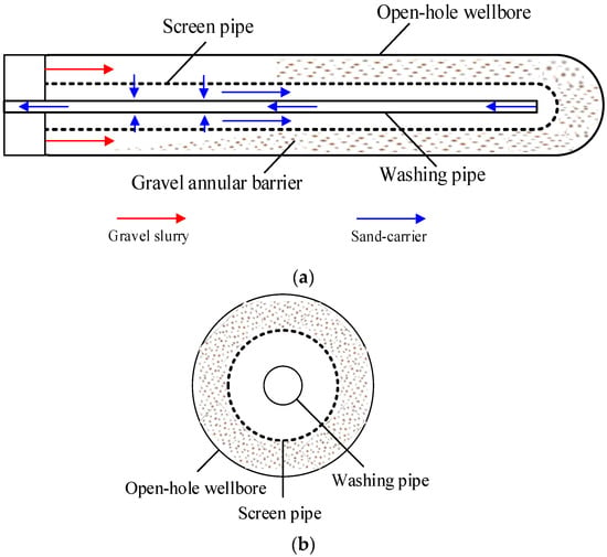
Figure 1.
Schematic diagram of horizontal well gravel packing. (a) Flow process of gravel packing, (b) cross-section view.
Since the early 1970s, experimental research on the horizontal well gravel packing has been conducted. Gruesbeck et al. [6] initially introduced the concept of equilibrium bank and described the gravel packing process based on a physical simulation test. As computer technology advanced, a series of numerical simulation studies of gravel packing have been conducted [7,8,9,10,11,12], and some beneficial study results have been obtained. In recent years, with the application of horizontal wells in offshore natural gas extraction, open-hole gravel packing in offshore horizontal wells has garnered significant attention due to its potential in enhancing wellbore stability and production efficiency. In 2018, Johnson and Lee [13] developed a numerical model to predict the flow behavior within the gravel packing. In 2020, Rodrigues et al. [14] presented a detailed analysis of a successful gravel packing project in the Gulf of Mexico. They discussed the challenges encountered, the solutions implemented, and the ultimate improvements in well production and stability.
With the exploitation of offshore deep-water oil and gas, the issue of gravel packing in deep-water horizontal wells has garnered increasing attention. In 2021, Wen et al. [15] carried out a series of friction calculations and packing effect analysis for gravel packing in deep-water horizontal wells. In 2022, Yu et al. [16] investigated the numerical simulation and application analysis of gravel packing in deep-water HT/HP horizontal wells.
In recent years, in order to further enhance the efficiency of offshore deep-water oil and gas production, the application of deep-water long horizontal wells has gradually increased [17,18,19,20,21], resulting in longer horizontal well sections. Accordingly, gravel packing in deep-water long horizontal wells will also face more challenges [22,23,24,25,26], resulting in a higher risk of forming a sand bridge in α-wave packing and a narrower feasible pressure scope in β-wave packing. Thus, to avoid forming sand bridge blockage in α-wave packing and fracturing reservoirs in β-wave packing, we need to optimize various packing parameters to maximize the gravel packing length of deep-water horizontal wells. That is to say, how to optimize the packing parameters is crucial for deep-water long horizontal gravel packing [27,28,29,30,31,32,33]. For the optimization design of gravel packing in horizontal wells, traditional methods are mostly based on on-site experience. However, in order to ensure the success of gravel packing, they tend to be conservative and choose a relatively shorter designed packing length. In addition, the trial-and-error method has also been frequently adopted in recent years. This refers to the process where field engineers repeatedly select the designed packing length and key packing parameters based on experience to conduct packing simulation calculations. Then, based on the simulation results, they judge whether the designed packing length is feasible and determine the reasonable designed packing length and key packing parameters. However, both of the above methods rely on on-site experience and cannot obtain the maximum packing length by optimizing the gravel packing parameters.
Thus, to assist the gravel packing design for deep-water long horizontal wells, this paper applies an improved artificial electric field algorithm (IAEFA) to optimize the packing parameters, aiming to obtain the optimal packing scheme and achieve the maximum length of gravel packing. Firstly, based on the calculations of the frictional resistance and pressure characteristics of gravel packing flow, an optimization model is proposed for gravel packing in deep-water horizontal wells, in which the gravel packing length is regarded as the objective function and the sand bridge blockage and reservoir fracturing are set as the constraints. Further, considering the characteristics of the proposed optimization model, an improved artificial electric field algorithm (IAEFA) is introduced for optimizing the key gravel packing parameters. Finally, for a specific case study, we conducted optimization calculations for gravel packing in a deep-water horizontal well and compared the optimization results of the improved artificial electric field algorithm (IAEFA) with different algorithm parameters. Through the above analysis, we obtained the optimal packing parameters, the maximum gravel packing length, as well as the friction distribution and pressure dynamic characteristics under the optimal scheme. This study provides a novel optimization approach for addressing the optimal design of gravel packing in deep-water long horizontal wells, which can also promote the application of deep-water long horizontal wells in deep-water oil and gas exploration.
2. Description of Gravel Packing Flow in Deep-Water Horizontal Well
2.1. Equilibrium Velocity and Equilibrium Sand Dune of α-Wave Packing
During the gravel packing process, the flow of slurry in the horizontal well section is a solid–liquid, two-phase flow. On one hand, the gravel particles in the slurry can be suspended in the sand carrier and move forward along with the sand carrier. Also, the flow velocity of the gravel slurry has a significant impact on the suspension and migration ability of gravel particles, and the higher the flow velocity is, the stronger the suspension and migration ability of gravel particles will be. On the other hand, under the action of gravity, the gravel particles will settle down and form sand dunes in the wellbore-screen annulus.
Typically, when gravel slurry initially enters a horizontal wellbore in α-wave packing, the large cross-sectional area of the wellbore annulus results in a relatively low flow velocity , which makes gravel settling a more significant phenomenon. However, as the gravel sand dune gradually forms, the cross-sectional area of the wellbore annulus decreases, and the flow velocity increases, leading to a gradual enhancement in the suspension and transport capabilities of the gravel particles.
where is the flow velocity of gravel slurry, is the volume flow rate (pump rate), and is the cross-sectional area of wellbore annulus. Therefore, as the flow velocity increases, the suspension of gravel particles becomes stronger, and the settlement and lifting of gravel particles gradually reach equilibrium. The height of sedimentary sand dunes no longer increases, forming a stable sand dune. The equilibrium velocity could be defined as the flow velocity at which the settlement and lifting of gravel particles reach equilibrium, and can be written as follows [6],
where is the equilibrium velocity, is the terminal settling velocity of gravel particle, is the hydraulic radius of cross-section of wellbore annulus under equilibrium condition, is the volume concentration of gravel particle under equilibrium state, is the density of gravel particle, is the average diameter of gravel particle, and are the density and viscosity of sand-carrying fluid, respectively.
Correspondingly, the stable sand dune under the equilibrium velocity is referred to as the equilibrium sand dune of α-wave packing. Commonly, it is generally believed that the height of the equilibrium sand dune of α-wave packing should be maintained at 65%–85% of the wellbore diameter [34]. However, when the height of sand dune exceeds 85% of the wellbore diameter, it is believed that sand bridge blockage will occur, causing the rear of the blockage point to be unable to pack, and α-wave packing will terminate prematurely. Therefore, in order to avoid sand bridge blockage in α-wave packing and achieve complete packing of the whole horizontal well section, it is crucial to select appropriate packing parameters, including the pump rate, the density of sand-carrier fluid, the gravel density and size, as well as the dimensions of the screen pipe and washing pipe. The above key packing parameters will also serve as the optimization variables that need to be optimized in this study.
2.2. Flow Friction Resistance of Gravel Packing in Deep-Water Horizontal Well
Normally, the gravel packing process in horizontal wells could be divided into three stages, including the gravel slurry injection stage, the α-wave packing stage, and the β-wave packing stage. According to the flow characteristics of each stage, the flow friction resistance calculation models [35] for each respective stage are given as follows.
2.2.1. Injection Stage
The gravel slurry injection stage commences with the pumping of gravel slurry at the wellhead and continues until the gravel slurry reaches the heel of the horizontal section at the bottom hole. In this stage, after the gravel slurry is pumped into the pipe string, the gravel slurry gradually displaces the original fluid (typically, the sand-carrying fluid) within the string and the horizontal wellbore, propelling it forward, and the displaced fluid returns through the washing pipe. Therefore, in the injection stage, the horizontal wellbore undergoes a single-phase flow of pure sand-carrying fluid, and the friction loss within the horizontal wellbore can be expressed as follows:
where is the friction loss within the horizontal wellbore in the injection stage, is the friction coefficient, is the density of the sand-carrying fluid, is the pump rate (volume flow rate), is the length of the horizontal wellbore, and and are the cross-sectional area and the hydraulic diameter of the wellbore annulus, respectively.
2.2.2. α-Wave Packing Stage
The α-wave packing stage refers to the stage that starts from the moment when gravel slurry enters the horizontal wellbore and continues until the gravel slurry reaches the end of the horizontal wellbore. In this stage, as the gravel slurry flows from the heel to the toe of the horizontal wellbore, it gradually displaces the original sand-carrying fluid within the wellbore. Therefore, the horizontal wellbore can be divided into two parts: from the heel to the propagation front of the gravel slurry, it is the flow of gravel slurry, while from the propagation front of the gravel slurry to the toe of the horizontal wellbore, it is the flow of pure sand-carrying fluid. The total friction loss in horizontal wellbore can be described as follows,
where is the friction loss within the horizontal wellbore in the α-wave packing stage, is the density of gravel slurry, is the current completed packing length of α-wave, and and are the cross-sectional area and the hydraulic diameter of wellbore annulus above the sand dune, respectively.
As mentioned before, during the α-wave packing stage, as the gravel slurry flows from the heel to the toe of the horizontal wellbore, the α-wave equilibrium sand dune will gradually form from the heel to the toe. Thus, the most important thing in the α-wave packing stage is to avoid the formation of sand bridge blockage, which may lead to the premature termination of α-wave packing and failure to achieve complete packing of the whole horizontal wellbore.
2.2.3. β-Wave Packing Stage
After the completion of the α-wave packing, the β-packing stage commences. During the β-wave packing stage, gravel is back packed from the end of the wellbore into the void space atop the α-wave equilibrium sand dune, packing the remaining annulus space above the α-wave equilibrium sand dune. This process continues until the gravel reaches the onset of the horizontal section. Simultaneously, the sand-carrying fluid permeates through the deposited gravel layer, flows through the washing-screen annulus, and is subsequently returned via the washing pipe. This entire process, where gravel packs the remaining annulus space above the α-wave equilibrium sand dune, is designated as the β-wave packing stage. In the β-wave packing stage, the total friction loss in the horizontal wellbore can be described as follows:
where is the friction loss within the horizontal wellbore in the β-wave packing stage, is the current completed packing length of β-wave, and and are the inner diameter of screen pipe and outer diameter of washing pipe, respectively.
During the β-wave packing stage, the sand-carrying fluid needs to penetrate through the α-wave-deposited sand dune, flow through the relatively long washing-screen annulus, and then return through the washing pipe. This process generates significant frictional loss, and as the β-wave packing length increases, the pressure in wellbore rises rapidly, significantly increasing the risk of reservoir fracturing. Therefore, in the β-wave packing stage, it is crucial to closely monitor and control the wellbore pressure to ensure it does not exceed the fracturing pressure of the reservoir, thereby avoiding reservoir fracturing.
3. Optimization Model for Maximizing the Length of Gravel Packing
3.1. Achievable Gravel Packing Length
As mentioned above, to achieve complete packing of the entire horizontal wellbore section requires satisfying two conditions simultaneously:
- (1)
- The α-wave packing must be capable of completing the packing of the entire horizontal wellbore section, meaning that the packing length of the α-wave () should reach the design length of the entire horizontal wellbore (), i.e., = .
- (2)
- The β-wave packing must also be able to complete the packing of the entire horizontal wellbore section, indicating that the packing length of the β-wave () should reach the design length of the entire horizontal wellbore (), i.e., = .
In this scenario, the design length of the horizontal wellbore is referred to as a feasible length for gravel packing. Conversely, when < or < , it indicates that under the current packing parameters, it is unable to achieve the designed packing length . Instead, the achievable gravel packing length needs to be determined by the smaller one between and ,
That is to say, represents the actual achievable gravel packing length under the current packing parameters, and the selection of these packing parameters will have a direct and significant influence on .
3.2. Optimization Model
Herein, the key parameters of gravel packing are regarded as optimization variables, including the pump rate , the density of the sand carrying fluid , the density of gravel particle , the average diameter of gravel particle , sand ratio (volumetric concentration of gravel slurry) , and the inner and outer diameters of the screen pipe and wash pipe (, , and ). Correspondingly, the achievable gravel packing length could be written as a function form
where and are both functions with regards to optimization variables.
In order to achieve the optimal design of gravel packing in horizontal wells, we propose a corresponding optimization model, in which the maximization of achievable gravel packing length is regarded as the objective function, and avoiding the occurrences of sand bridge blockage (α-wave packing) and reservoir fracture (β-wave packing) are regarded as constraints of the model. The optimization model is as follows:
where is the sand dune ratio defined as , and are the height of α-wave sand dune and the diameter of horizontal wellbore, respectively, is the critical threshold for preventing sand bridge blockage, usually set at 0.85, and are the bottom hole pressure and fracturing pressure of reservoir, respectively.
4. IAEFA for Determining the Maximum Length of Gravel Packing
Here, an improved artificial electric field algorithm (IAEFA) is introduced for solving the optimization model (8), so as to determine the maximum length of gravel packing in a deep-water horizontal well.
4.1. Standard AEFA Algorithm
Artificial electric field algorithm (AEFA) is a population intelligence optimization algorithm and was proposed by Anita and Anupam in 2019 [36]. The AEFA algorithm ingeniously mimics the movement patterns of electrons within an electric field to achieve optimization. Each charge particle in an electric field is assimilated to an individual within a population, with its location denoting a candidate solution to the optimization problem. For an optimization problem with optimization variables, the position of the i-th charge particle is denoted by , and the velocity of the i-th charge particle is denoted by .
During iterative optimization, charge particles in the p-dimensional search space evolve under electrostatic forces, converging towards the optimal position to solve the optimization problem. Based on Coulomb’s law, the t-th iteration attractive force between particles i and j is mathematically formulated as:
where represents the attraction force between particles i and j at t-th iteration, N represents the population size, is the Coulomb’s coefficient at t-th iteration, and are the charges of particles i and j, respectively, is the Euclidian distance between particles i and j at t-th iteration, represents a very small positive constant, and denotes the current best position of charge particle j. In the standard AEFA algorithm, the Coulomb’s coefficient is written as:
where represents the initial Coulomb’s coefficient, represents the maximum iterations, and represents the parameter. The charge of each particle can be expressed as a function that depends upon the fitness value of the particle, the best and the worst fitness values of all particles within the population:
where represents the fitness function, and represent the best and worst fitness value of the whole population at the t-th iteration. The resultant force experienced by the particle i, resulting from the collective action of all particles within the population, can be mathematically represented as:
where is a random number generation function that can generate random numbers between 0 and 1. Accordingly, the velocity and position of the particle i can be updated in the subsequent iteration as below:
where is the inertia factor defined as , is the acceleration factor defined as , is the acceleration of the particle i, and is the unit mass of the particle i.
4.2. Improvement Strategy of IAEFA Algorithm
The magnitude of Coulomb’s coefficient has a direct influence on the strength of the electrostatic force, which in turn determines the acceleration and velocity of particles. Typically, during the initial stages of the search process, a larger adjustment in the search velocity is deemed rational to facilitate a comprehensive global search within the feasible region. This demands a larger value for Coulomb’s coefficient at the initial stage. Conversely, as the search progresses, aiming for local search precision, a minor adjustment in search velocity becomes appropriate, demanding a reduction in the value of Coulomb’s coefficient . However, in the standard artificial electric field algorithm (AEFA), Coulomb’s coefficient is expressed as an exponential function that undergoes a sharp decline with the increasing number of iterations t. This implies that while AEFA excels in local search capabilities, it falls short in achieving efficient global search.
To address this imbalance between global and local search capabilities in the standard AEFA, Cheng et al. [37] introduced an improved artificial electric field algorithm (IAEFA). In this improved algorithm, a novel adjustment strategy for Coulomb’s coefficient is formulated using the log-sigmoid function. This strategy is defined as follows:
where b and c represent the initial parameter and step parameter, respectively.
5. The Proposed Research Framework
Figure 2 outlines the procedures of the proposed methodology for determining the maximum length of gravel packing in a deep-water horizontal well.
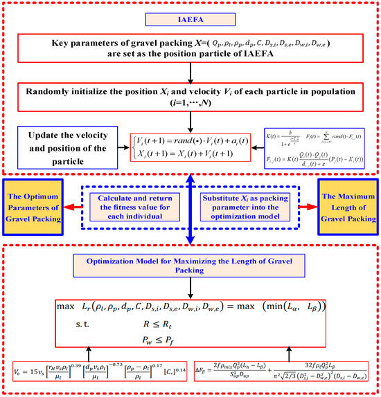
Figure 2.
Schematic diagram of horizontal well gravel packing.
The specific optimization algorithm process for determining the maximum gravel packing length is as follows:
Step 1: Establish the fundamental configurations for the IAEFA algorithm and target packing well. Set the basic parameters of the IAEFA algorithm, including, population size N, maximum number of iterations T, initial parameter b, step parameter c, etc. For the target packing well, the critical parameters include water depth Hw, vertical depth Hv, open hole wellbore diameter Dw, etc.
Step 2: Initiate the population with random packing parameters. Within the defined range of each packing parameter, the IAEFA’s initial population is randomly generated. Each individual within this population represents a unique set of packing parameters, serving as potential solutions to the optimization problem.
Step 3: Evaluate equilibrium sand dune, friction loss, and wellbore pressure. Each individual in the population is utilized as a set of the packing parameters. These parameters are then employed to simulate the gravel packing process, determining the resulting equilibrium sand dune. Subsequently, the friction loss and wellbore pressure during the packing operation are calculated. These metrics provide insights into the efficiency and feasibility of the current packing strategy.
Step 4: Assess fitness based on objective function. Taking into account the constraints imposed by sand bridge blockage and allowable packing pressure, the objective function is evaluated for each set of packing parameters. This function quantifies the achievable packing length , which serves as the primary criterion for evaluating the quality of a solution. The resulting value is then assigned as the fitness score to the corresponding individual in the IAEFA algorithm, guiding the search towards more promising solutions.
Step 5: Iterate and evolve the population. Based on their fitness scores, the IAEFA algorithm updates the velocity and position of each individual within the population. This evolutionary process encourages individuals with higher fitness (i.e., longer achievable packing length ) to influence the next generation’s composition, thereby moving the search closer to the optimal solution.
Step 6: Terminate or continue the iteration cycle. The algorithm checks if the maximum number of iterations T has been reached. If the current iteration count t is less than T, the process returns to Step 3, continuing the cycle of evaluation, adaptation, and evolution. However, if the current iteration count t is equal to or exceeds T, the algorithm terminates, and the optimal individual position with the highest fitness score in the final generation population is the optimal packing parameter, and its fitness value is the achievable maximum length of gravel packing.
6. Case Study and Result Discussion
6.1. Basic Parameters and Optimization Variables
Here, we consider a deep-water natural gas well as the target well to conduct a case study. The relevant parameters of the well are listed in Table 1.

Table 1.
The basic parameters of target well.
Also, as stated above, the pump rate , the density of the sand carrying fluid , the density of gravel particle , the average diameter of gravel particle , the sand ratio (volumetric concentration of gravel slurry) , and the inner and outer diameters of the screen pipe and washing pipe (, , and ) are selected as optimization variables. The range of values for these key packing parameters is listed in Table 2.

Table 2.
The range of values for the key packing parameters.
6.2. Optimization Results Obtained by IAEFA
Commonly, the parameter values of optimization algorithms directly affect the optimization results of the problem. Therefore, in order to obtain better optimization results, the IAEFA algorithm with nine groups of different parameter combinations is used to optimize the maximum gravel packing length of the target horizontal well and compare and analyze the optimization results of different parameters.
Specifically, the parameters of the IAEFA algorithm we are discussing include the initial parameter b and step parameter c in Coulomb’s coefficient , the maximum value and minimum value in the inertia factor , the maximum value and minimum value in the acceleration factor , and population size N. Table 3 shows the values of nine groups of different parameter combinations.

Table 3.
Nine groups of different parameter combinations.
Next, for the target horizontal well and optimization variables in Section 6.1, we will use nine groups of different parameter combinations in Table 3 for optimization calculations.
For nine groups of different parameter combinations (Case 1~Case 9) listed in Table 3, Figure 3a–i presents the curves of the objective function values varying with iterations of IAEFA under different parameter combinations. In Figure 3, we can find that under each parameter combination (Case 1~Case 9), the objective function value could converge rapidly and achieve its maximum packing length within 20 iterations. However, there is a significant difference in the maximum packing length obtained by the IAEFA algorithm under different parameter combinations. Among them, the IAEFA algorithm can obtain the longest packing length under three parameter combinations: Case 1, Case 7, and Case 9.
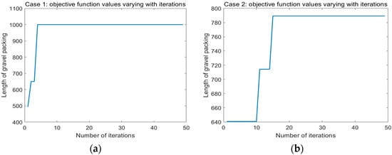
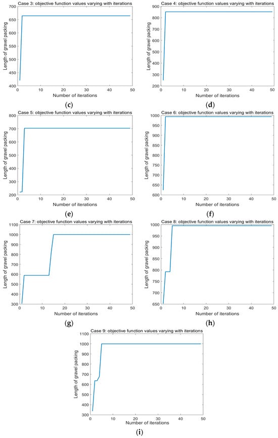
Figure 3.
The curves of the objective function values varying with iterations of IAEFA. (a) Case 1, (b) Case 2, (c) Case 3, (d) Case 4, (e) Case 5, (f) Case 6, (g) Case 7, (h) Case 8, (i) Case 9.
Table 4 presents the detailed optimization results for nine parameter combinations, including the maximum packing length and corresponding optimal packing parameter values. From the detailed results in Table 4, it is evident that under the combinations of Case 1, Case 7, and Case 9, the optimized maximum packing length can reach 1000.22 m. For Case 6 and Case 8, the optimized maximum packing lengths are 993.97 and 995.53 m, respectively. Meanwhile, for Case 2 to Case 5, the optimized maximum packing lengths are relatively shorter, ranging from 664.28 to 851.78 m. Figure 4 provides a visual comparison of the maximum packing length under 9 different parameter combinations.

Table 4.
The optimization results under nine groups of different parameter combinations.
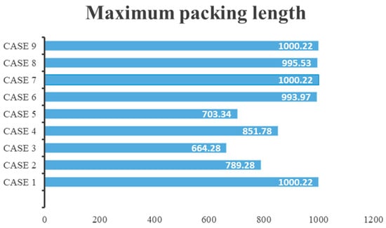
Figure 4.
The maximum packing length under nine groups of different parameter combinations.
6.3. Simulation Results of Gravel Packing under Optimal Packing Parameters
Next, we will use the optimal packing parameter Case 9 (as shown in Table 5) to conduct a gravel packing simulation and analyze the dynamic characteristics of friction and pressure during the packing process.

Table 5.
Optimal packing parameter combinations for simulation.
Using the above packing parameters and setting the design length of the target horizontal well to the maximum packing length (= 1000.22 m), the basic simulation results of gravel packing in the target horizontal well are summarized in Table 6.

Table 6.
Simulation results of gravel packing in the target horizontal well.
From the results in Table 6, it can be observed that under the optimal packing parameters, both the α-wave and β-wave packing lengths have reached the design packing length, and the gravel packing of the target well can be successfully completed. Total time of gravel packing is 566.6 min, with the α-wave packing stage taking the longest, which is 357.13 min. Total amount of sand consumption is 54,050.94 lbs, with the largest amount of sand consumption for α-wave packing, which is 39,369.08 lbs.
Figure 5 presents the varying curve of bottom hole pressure during the gravel packing process. In Figure 5, we can observe that during the injection stage (0–76.29 min), the bottom hole pressure remains around 9780 psi; during the α-wave packing stage (76.29–433.42 min), the bottom hole pressure slowly rises from 9788 psi to 9837 psi; and during the β-wave packing stage (433.42~566.6 min), the bottom hole pressure rapidly increases from 9837 psi to 9986 psi. When the β-wave packing is completed, the bottom hole pressure (9986 psi) is still much lower than the reservoir fracture pressure (1025.6 psi), indicating that the gravel packing operation did not cause formation fracture.
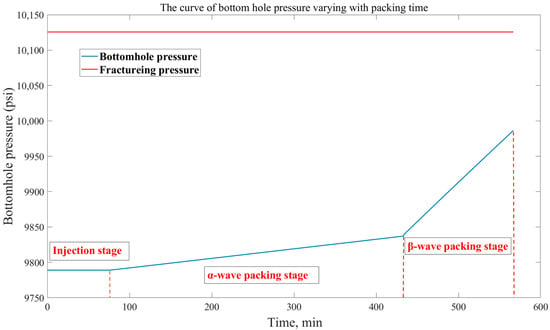
Figure 5.
The curve of bottom hole pressure varying with packing time.
Figure 6 presents the varying curves of frictional resistances inside various parts during the gravel packing process. In Figure 6, it could be observed that the frictional resistances inside the string pipe, washing pipe, and string-casing annulus all remain stable during the whole gravel packing process, at around 181 psi, 265 psi, and 78 psi, respectively. On the contrary, the friction inside the horizontal wellbore undergoes significant changes during the packing process. The friction in the horizontal wellbore remains stable during the injection stage, slowly increasing in the α-wave packing stage and rapidly increasing in the β-wave packing stage, which is consistent with the description of the mechanism of gravel packing.
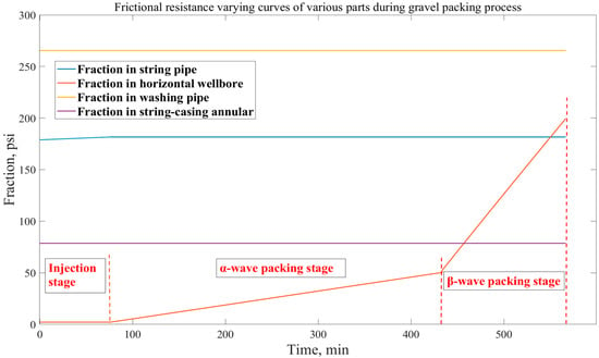
Figure 6.
Frictional resistance variation curves of various parts during gravel packing process.
7. Conclusions
This paper proposed a novel optimization design approach for gravel packing in deep-water horizontal wells by using the IAEFA algorithm to determine the maximum packing length and corresponding optimal packing parameters. The proposed optimization design approach can promote the application of deep-water long horizontal wells in deep-water oil and gas exploration. The most important findings from the current investigation are:
The case study shows that the optimization design approach based on the IAEFA algorithm proposed in this paper can effectively address the parameter optimization problem of deep-water horizontal well gravel packing and determine the maximum packing length. Using the IAEFA algorithm to optimize the target well in the case study, the maximum packing length of the target well can reach 1000.22 m, and the corresponding three sets of optimal packing parameters were obtained. The optimal packing parameters obtained were used to conduct a gravel packing simulation for the target well. The simulation results show that the total time of gravel packing in the target well is 566.6 min, and the total amount of sand consumption is 54,050.94 lbs. The bottom hole pressure remains stable with about 9780 psi during the injection stage, then slowly rises from 9788 psi to 9837 psi in the α-wave packing stage and rapidly increases from 9837 psi to 9986 psi in the β-wave packing stage. Also, the rapid increase of frictional resistance inside the horizontal wellbore mainly occurs during the β-wave packing stage.
The current work aimed to provide an intelligent optimization approach for the optimization design of deep-water horizontal well gravel packing so as to be capable of determining the maximum gravel packing length and optimal packing parameters. The optimization design process proposed in this study is deemed to promote the application of deep-water long horizontal wells in deep-water oil and gas exploration. In addition, in future work, we hope to further study the optimization design problem of gravel packing in directional inclined wells and consider the influence of random and uncertain factors of packing parameters so as to make the model more generalizable and applicable.
Author Contributions
Conceptualization, L.Y. and S.Z.; methodology, L.Y. and H.L.; software, H.L. and L.Y.; validation, L.Y. and H.L.; investigation, L.Y. and H.L.; writing—original draft preparation, L.Y.; writing—review and editing, H.L.; supervision, H.L.; project administration, L.Y. and S.Z.; data curation, Z.F.; funding acquisition, H.L. All authors have read and agreed to the published version of the manuscript.
Funding
This research was funded by the National Natural Science Foundation of China, grant No. 51879272; the Fundamental Research Funds for the Central Universities, China, grant No. 22CX03022A and the project [grant No. 24-4-4-zrjj-173-jch] supported by Qingdao Natural Science Foundation.
Institutional Review Board Statement
Not applicable.
Informed Consent Statement
Not applicable.
Data Availability Statement
Data is contained within the article.
Conflicts of Interest
The authors declare no conflicts of interest.
References
- Yu, Z.; Amdahl, J. A review of structural responses and design of offshore tubular structures subjected to ship impacts. Ocean Eng. 2018, 154, 177–203. [Google Scholar] [CrossRef]
- Jeanpert, J.; Banning, T.; Abad, I.; Mbamalu, J. Successful installation of horizontal openhole gravel-pack completions in low fracture gradient environment: A case history from deepwater West Africa. In Proceedings of the SPE International Conference and Exhibition on Formation Damage Control, Lafayette, LA, USA, 21 February 2024; SPE: Kuala Lumpur, Malaysia, 2018; p. 189492-MS. [Google Scholar]
- Ali, S.; Grigsby, T.; Vitthal, S. Advances in horizontal openhole gravel packing. SPE Drill. Complet. 2006, 21, 23–30. [Google Scholar] [CrossRef]
- Weaver, J.; Knox, J. Evaluation of Steam Resistance of Gravel-Packing Materials. SPE Prod. Eng. 1992, 7, 155–159. [Google Scholar] [CrossRef]
- Johnson, P.; Williams, R. A novel cyclic gravel packing method for offshore horizontal wells. SPE Drill. Complet. 2019, 34, 132–140. [Google Scholar]
- Gruesbeck, C.; Salathiel, W.M.; Echols, E.E. Design of gravel packs in deviated wellbores. J. Pet. Technol. 1979, 31, 109–115. [Google Scholar] [CrossRef]
- Lee, K.; Kim, H. Multi-physics coupling model for predicting gravel pack stability and durability. J. Pet. Technol. 2020, 72, 56–63. [Google Scholar]
- Zhou, S.; Li, Z.; Dong, C. The advances of numerical simulation for gravel packing in horizontal wells. Mech. Eng. 2009, 31, 9–15. [Google Scholar]
- Li, A.; Yang, L. Numerical simulation study of gravel packing in horizontal well. Acta Pet. Sin. 2002, 23, 102–106. [Google Scholar]
- Pillai, P.; Lin, C.C.; Brege, J.; Mohan, R.; Mohan, E. Industry first openhole alternate path gravel pack completion in hpht environment: Fluid development and case history. In Proceedings of the SPE Annual Technical Conference and Exhibition, Dubai, United Arab Emirates, 21–23 September 2021; SPE: Kuala Lumpur, Malaysia, 2021; p. 206048-MS. [Google Scholar]
- Alexander, K.; Bruce, D.; Williamson, C.; Moses, N.; Ismayilov, E. Evolution of open-hole gravel pack methodology in a low frac-window environment: Case histories and lessons learned from the Kraken field development. In Proceedings of the SPE Annual Technical Conference and Exhibition, Calgary, AB, Canada, 30 September–2 October 2019; SPE: Kuala Lumpur, Malaysia, 2019; p. 195937. [Google Scholar]
- Rice, R. A Case Study of Plastic Plugbacks on Gravel Packed Wells in the Gulf of Mexico. In Proceedings of the SPE Production Operations Symposium, Oklahoma, OK, USA, 7–9 April 1991; SPE: Kuala Lumpur, Malaysia, 1991; p. 21671-MS. [Google Scholar]
- Johnson, P.; Lee, K. Numerical modeling of flow behavior within open-hole gravel packs in offshore wells. J. Pet. Technol. 2018, 70, 43–50. [Google Scholar]
- Rodrigues, K.; Kevin, W.; Lawrence, R.; Kerimov, N.; Henry, I.; Brune, L.; Spicer, J.; Nwafor, C.; Gutierrez, C.; Filbrandt, J. Application of new technologies to GoM for a successful open hole gravel pack. In Proceedings of the SPE International Conference and Exhibition on Formation Damage Control, Lafayette, LA, USA, 19–21 February 2020; SPE: Kuala Lumpur, Malaysia, 2020; p. 199338. [Google Scholar]
- Wen, M.; Huang, H.; Zhou, S.; Fan, B.; Qiu, H. Friction calculation and packing effect analysis for gravel packing in deepwater horizontal wells. Energy Sci. Eng. 2021, 9, 2380–2387. [Google Scholar] [CrossRef]
- Yu, Y.; Jiang, D.; Wang, H.; Diao, H.; Xiao, T.; Zhou, S. Simulation and application analysis of gravel packing in deepwater HT/HP wells. Energy Sci. Eng. 2022, 10, 3908–3917. [Google Scholar] [CrossRef]
- Gupta, V.; Jeanpert, J.; John, C.; Bose, R.; Agrawal, V. Elements in openhole gravel pack treatment design cycle: Case study in Indian ultra-deepwater. In Proceedings of the SPE Asia Pacific Oil & Gas Conference and Exhibition, Virtual, 17–19 November 2020; SPE: Kuala Lumpur, Malaysia, 2020; p. 202296-MS. [Google Scholar]
- Zhang, J.; Wang, L.; Li, H.; Chen, S. Numerical Investigation of Gravel Packing Process in Deepwater Horizontal Wells Considering Particle-Fluid Interactions. J. Pet. Sci. Eng. 2023, 230, 1–14. [Google Scholar]
- Smith, R.M.; Johnson, A.B. Advanced Simulation of Gravel Pack Performance in Complex Deepwater Environments. SPE J. 2022, 27, 2423–2438. [Google Scholar]
- Lee, K.H.; Kim, J.Y.; Park, C. W Optimization of Gravel Pack Design for Enhanced Production and Sand Control in Deepwater Horizontal Wells: A Numerical Study. J. Nat. Gas Sci. Eng. 2021, 8, 103591. [Google Scholar]
- Chen, X.; Yang, Y.; Liu, H. Dynamic Modeling and Simulation of Foam-Assisted Gravel Packing in Deepwater Horizontal Wells. J. Energy Resour. Technol. 2020, 142, 112901–112912. [Google Scholar]
- Wang, M.; Zhang, X.; Zhou, D. Numerical Analysis of Gravel Packing Effectiveness in Deepwater Horizontal Wells with High-Angle Deviations. SPE Drill. Complet. 2019, 34, 269–280. [Google Scholar]
- Wu, J.; Li, Z.; Yang, Z. Experimental and Numerical Study on the Flow Behavior of Gravel-Packing Fluids in Deepwater Horizontal Wells. J. Pet. Explor. Prod. Technol. 2018, 8, 1109–1121. [Google Scholar]
- Liu, Y.; Huang, H. Simulation of Complex Flow Dynamics During Gravel Packing in Deepwater Horizontal Wells Using CFD Methods. J. Pet. Sci. Eng. 2017, 158, 710–722. [Google Scholar]
- Zhang, L.; Guo, H. Optimization of Gravel Pack Design for Sand Control in Deepwater Horizontal Wells Based on Numerical Simulation. J. Nat. Gas Sci. Eng. 2016, 3, 1257–1267. [Google Scholar]
- Park, S.; Choi, K. Numerical Investigation of Particle Transport and Deposition During Gravel Packing in Deepwater Horizontal Wells. J. Pet. Technol. Altern. Fuels 2015, 6, 162–173. [Google Scholar]
- Kim, J.; Kim, M. Advanced Simulation of Gravel Packing Performance Considering Non-Newtonian Fluid Behavior in Deepwater Horizontal Wells. SPE Reserv. Eval. Eng. 2014, 17, 359–370. [Google Scholar]
- Zhang, J.; Liu, H. Enhanced Optimization of Gravel Pack Design for Deepwater Horizontal Wells Based on CFD-PSO Hybrid Method. SPE J. 2023, 28, 3456–3470. [Google Scholar]
- Kim, M.; Choi, K. Multi-Objective Optimization of Gravel Packing in Horizontal Wells Considering Production Efficiency and Sand Control. J. Nat. Gas Sci. Eng. 2022, 9, 106873. [Google Scholar]
- Wu, X.; Wang, D.; Chen, Z. Intelligent Optimization of Gravel Packing Parameters for Horizontal Wells in Unconsolidated Reservoirs. J. Pet. Explor. Prod. Technol. 2021, 11, 1435–1448. [Google Scholar]
- Liu, Y.; Zhang, L. Optimization of Foam-Assisted Gravel Packing in Horizontal Wells Using a Coupled CFD-Particle Tracking Approach. SPE Prod. Oper. 2020, 35, 0569–1897. [Google Scholar]
- Chikwe, A.; Nwanwe, O.; Duru, U.; Nduwuba, G.O.; Duruonyeaku, A.N. Investigating the Impact of Sieve Analysis on the Choice of Gravel Pack Design for Wells in Unconsolidated Sandstone Formations in the Niger Delta. J. Eng. Res. Rep. 2023, 24, 39–49. [Google Scholar] [CrossRef]
- Peng, H.; Li, X.; Chen, Z.; Zhang, Y.; Ji, Y. Effect of gravel pack permeability on horizontal well productivity loss under secondary methane hydrate formation: Experimental optimization of 3D randomly distributed mixed sand pack. Appl. Energy 2024, 371, 123663. [Google Scholar] [CrossRef]
- Martins, A.L.; de Magalhaes, J.V.M.; Ferreira, M.V.D.; Calderon, A.; de Sa, A.N. Sand control in long horizontal section wells. In Proceedings of the Offshore Technology Conference, Houston, TX, USA, 1 January 2009. [Google Scholar]
- Martins, A.L.; de Magalhães, J.V.M.; Calderon, A.; Chagas, C.M. A mechanistic model for horizontal gravel-pack displacement. SPE J. 2005, 10, 229–237. [Google Scholar] [CrossRef]
- Anita; Yadav, A. AEFA: Artificial electric field algorithm for global optimization. Swarm Evol. Comput. 2019, 48, 93–108. [Google Scholar] [CrossRef]
- Cheng, J.; Xu, P.; Xiong, Y. An improved artificial electric field algorithm and its application in neural network optimization. Comput. Electr. Eng. 2022, 101, 108111. [Google Scholar] [CrossRef]
Disclaimer/Publisher’s Note: The statements, opinions and data contained in all publications are solely those of the individual author(s) and contributor(s) and not of MDPI and/or the editor(s). MDPI and/or the editor(s) disclaim responsibility for any injury to people or property resulting from any ideas, methods, instructions or products referred to in the content. |
© 2024 by the authors. Licensee MDPI, Basel, Switzerland. This article is an open access article distributed under the terms and conditions of the Creative Commons Attribution (CC BY) license (https://creativecommons.org/licenses/by/4.0/).