
A Task Allocation Method for Multi-AUV Search and Rescue with Possible Target Area


Abstract
1. Introduction
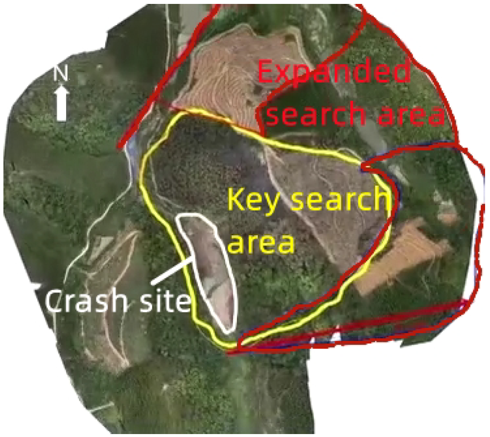
1.1. Motivation
1.2. Contributions
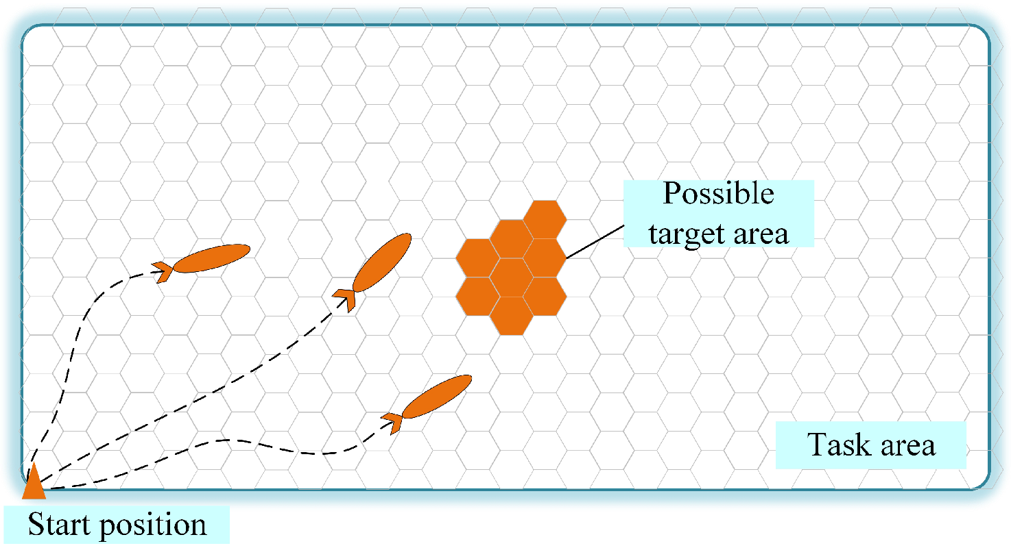
- This study first addresses the area partition problem with possible target areas in the multi-AUV area coverage task. The possible target areas are assigned to a minimum number of AUVs, which is beneficial to the performance of the mission.
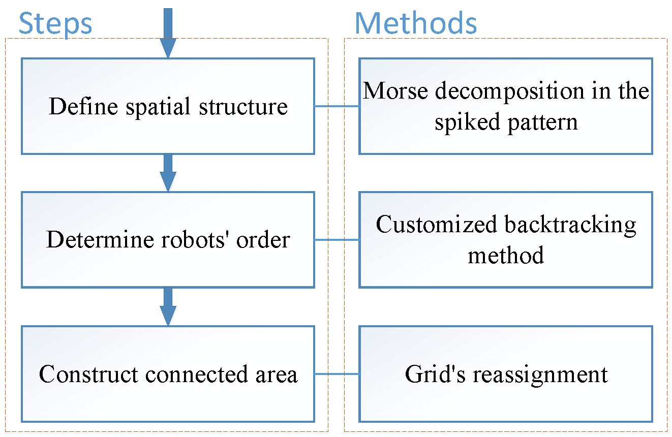
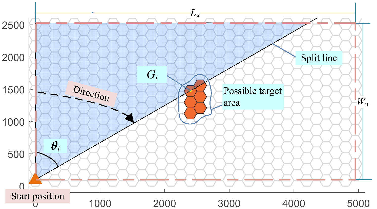
- The traditional Morse decomposition is extended to discrete task areas. The Morse decomposition in the spike pattern is adopted to define the discrete spatial structure of the workspace, as all AUVs started from the same initial position.
- A customized backtracking method is developed to determine the AUV order properly in order to balance the workload of the AUVs and reduce the number of AUVs covering the possible target areas. The generated solution employing the customized backtracking method is stable and globally optimal.
2. Related Work
3. Problem Definition and Assumptions
4. Morse-Decomposition-Based Discrete Area Partitioning Method
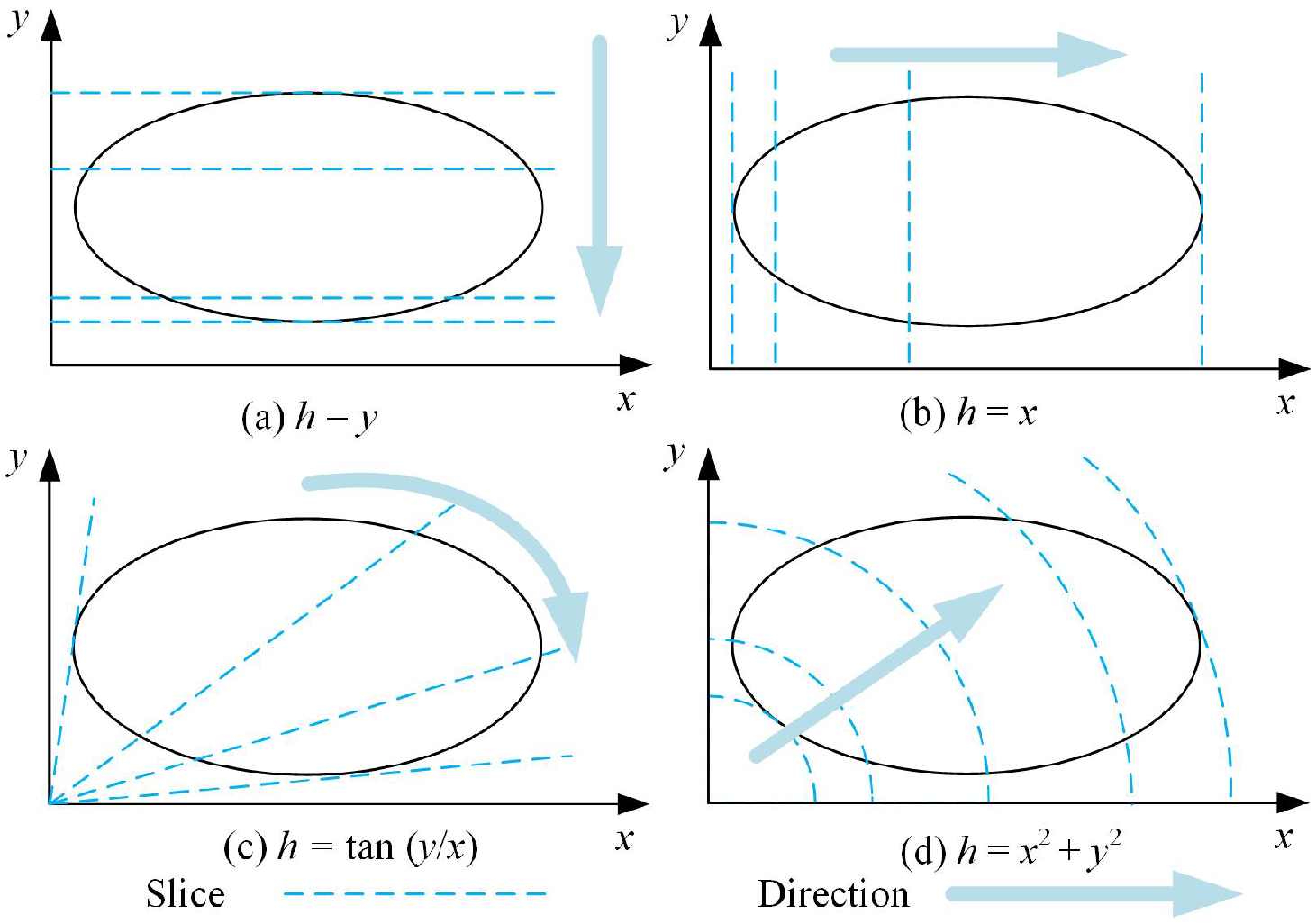
4.1. Define the Structure of the Discrete Task Area
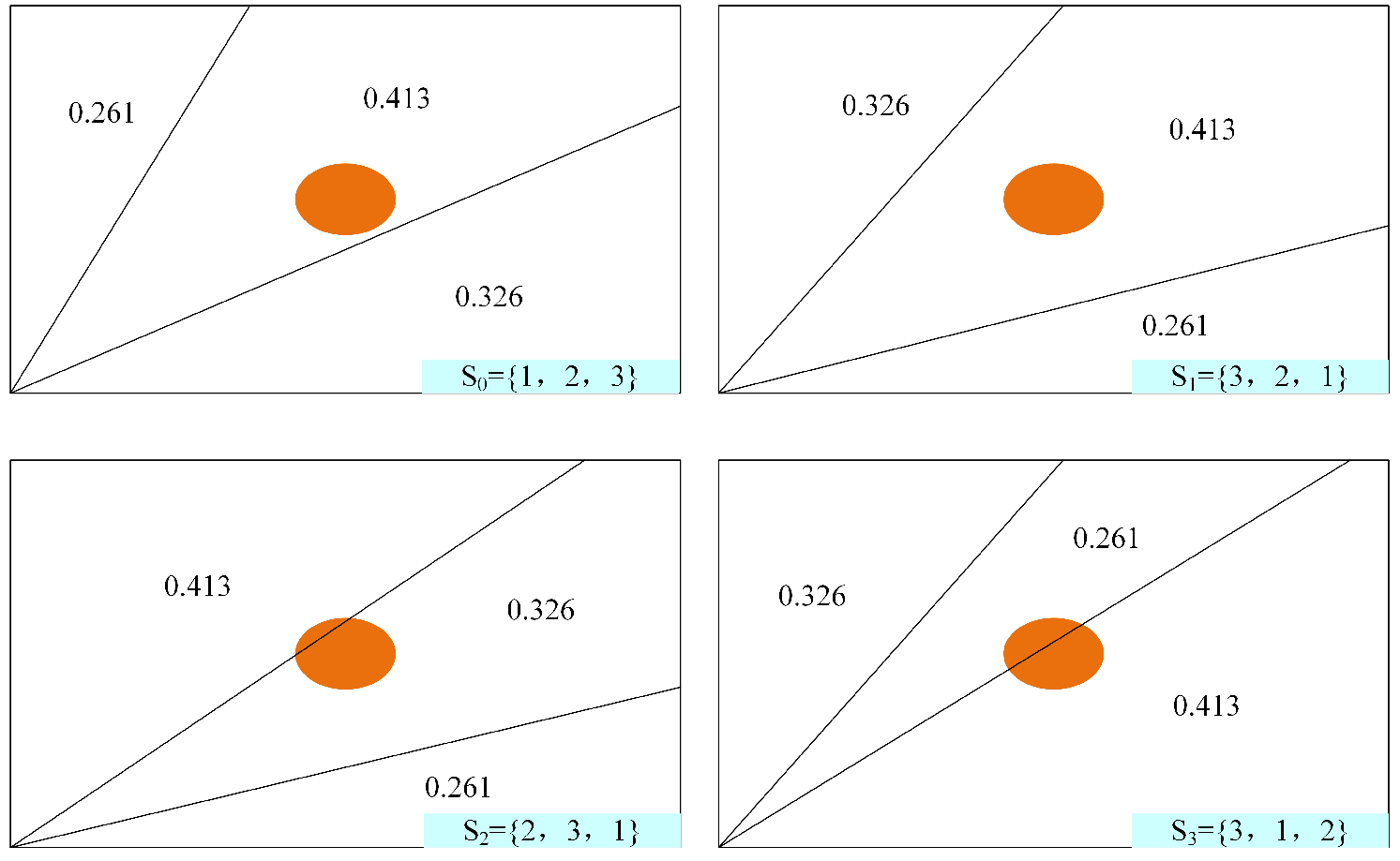
4.2. Determine the Optimal Split Lines
4.2.1. Objective Functions of
4.2.2. Find the Optimal
| Algorithm 1 Customized backtracking method in Morse decomposition. |
| Input: Output: , , S 1: Initialize: , 2: while do 3: while do 4: if is available then 5: ←j 6: break 7: else 8: j←j +1 9: ← 10: compare and record 11: 12: end if 13: end while 14: if then 15: , j← 1 16: else 17: BACKTRACKING 18: end if 19: if all elements in are settled then 20: calculate 21: , 22: end if 23: end while 24: if S is ∅ then 25: ← 26: 27: calculate 28: end if |
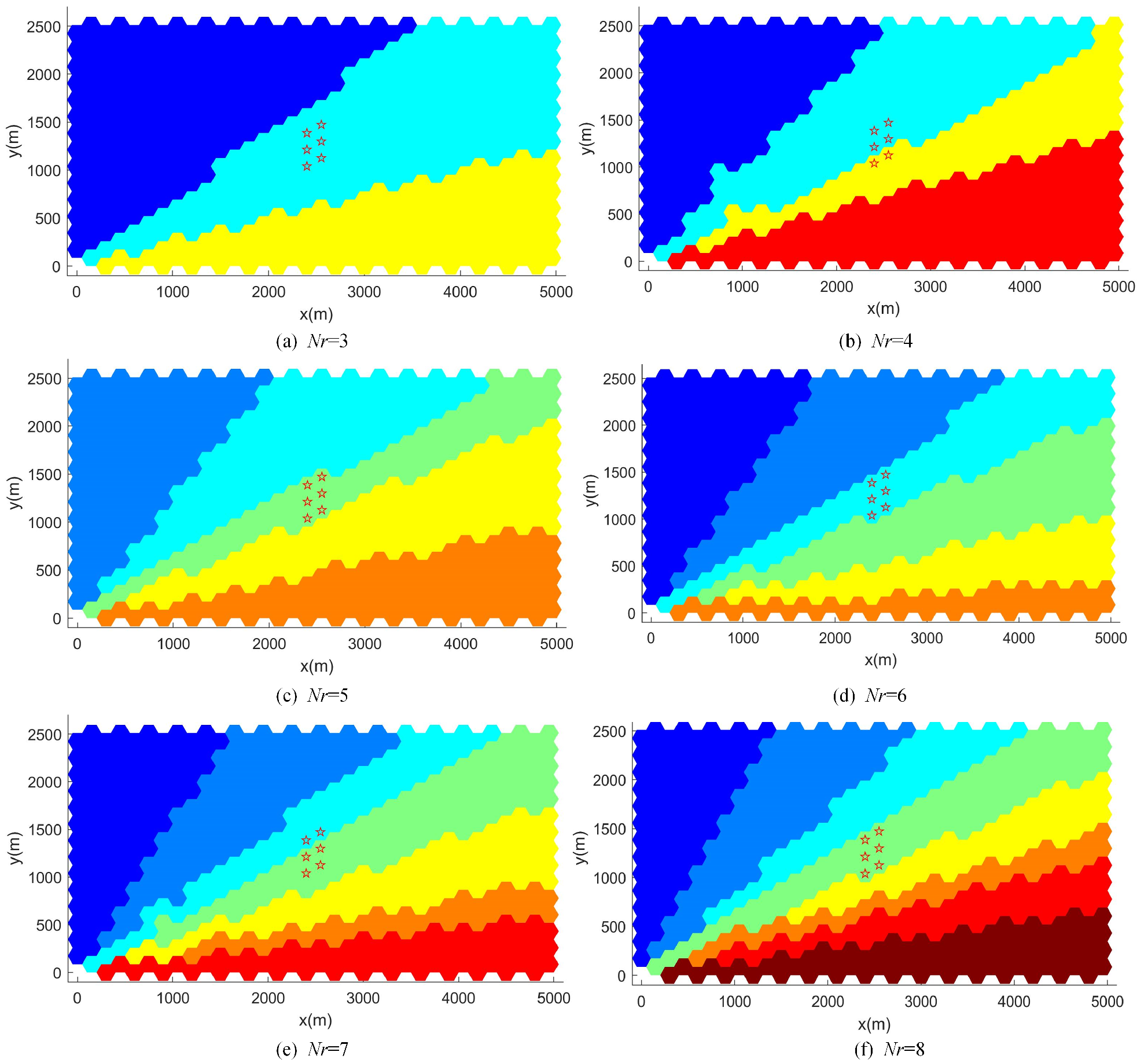
4.3. Construct Connected Subareas
| Algorithm 2 Constructing connected areas. |
| Input: ,, Output: ,, 1: for to do 2: Calculate , 3: Calculate and 4: while do 5: 6: 7: if then 8: 9: else 10: 11: end if 12: Update , , , and 13: end while 14: end for |
5. Simulation Results
5.1. Scenarios and Performance Metrics
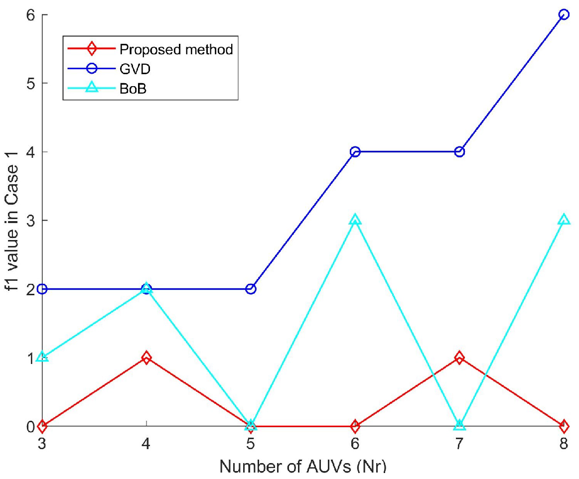
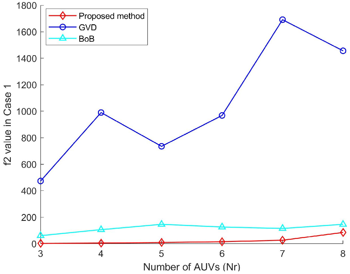
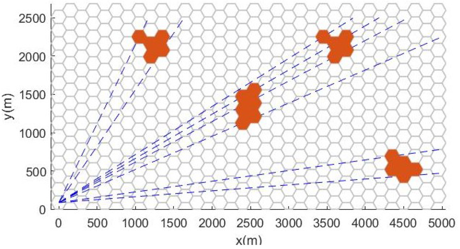
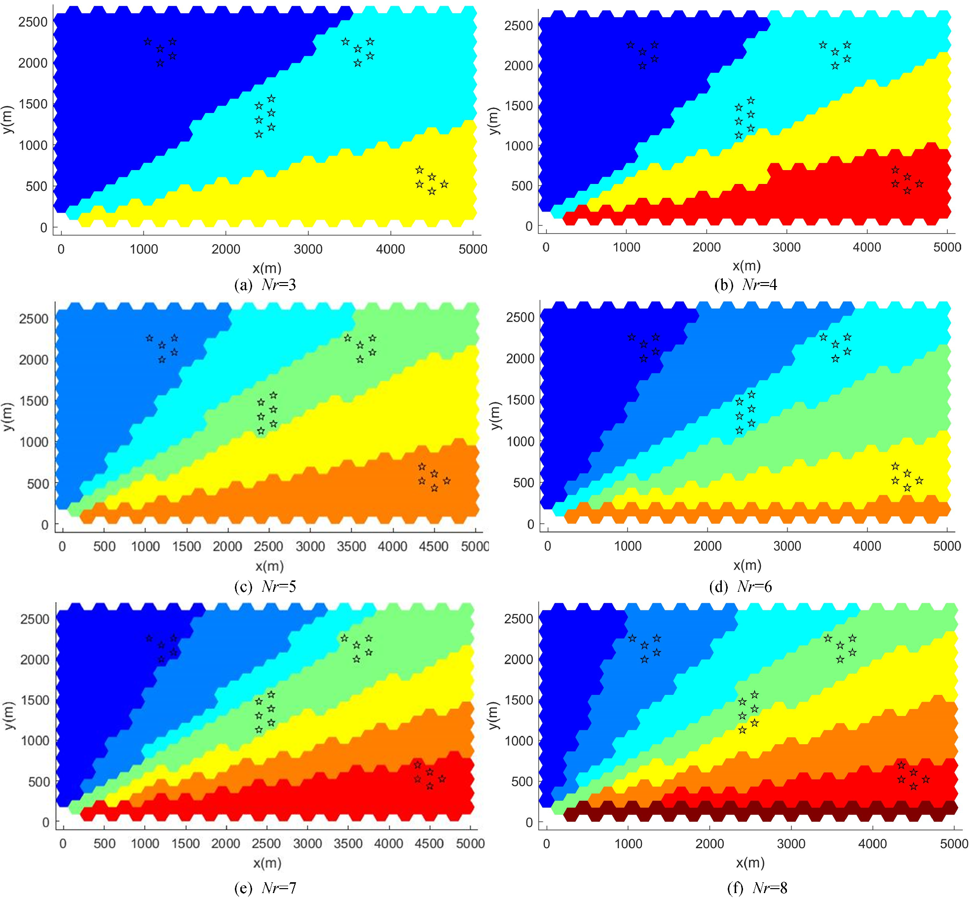
5.2. Case 1: One Special Zone
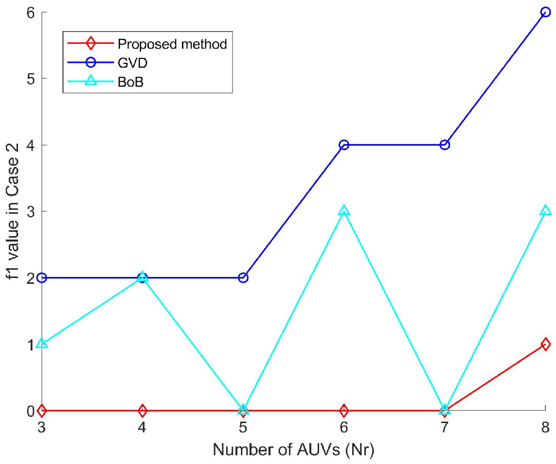
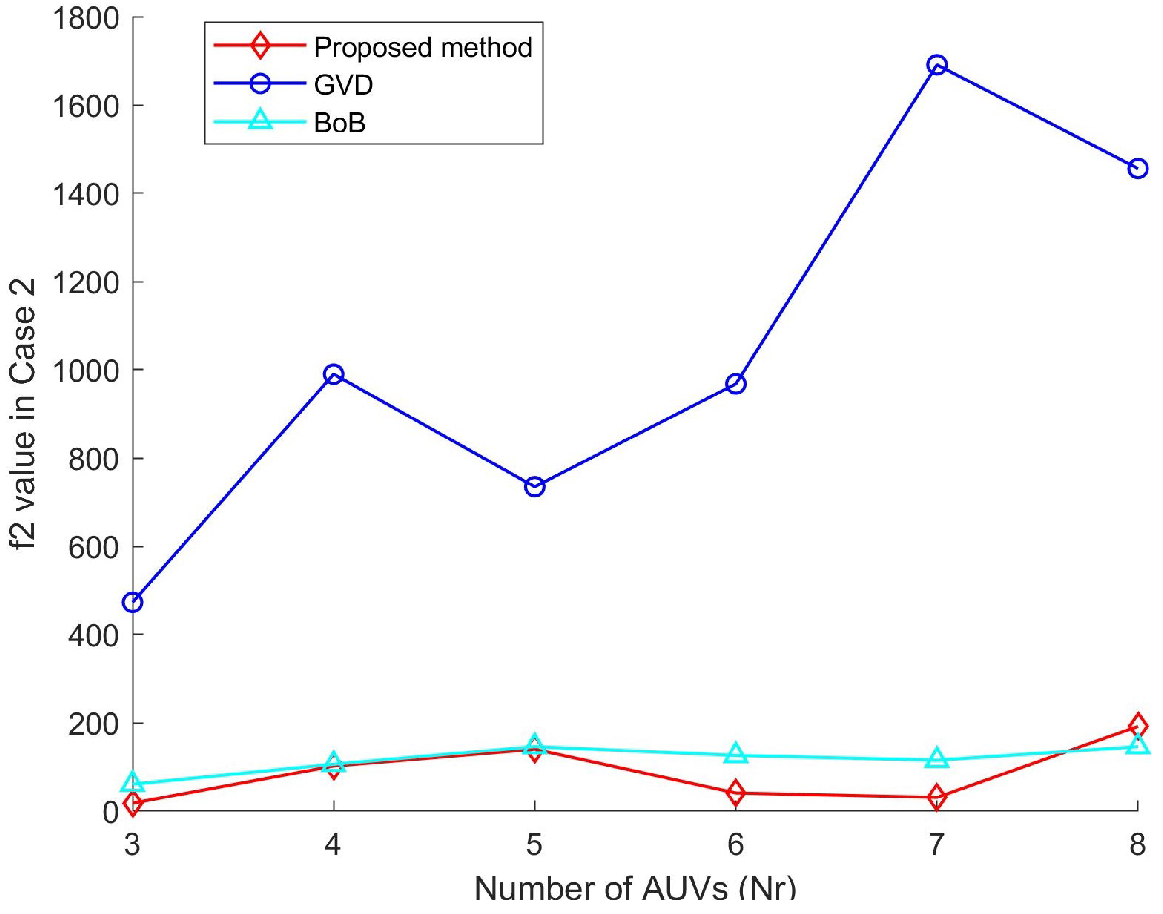
5.3. Case 2: Scattered Special Zones
6. Conclusions
Author Contributions
Funding
Institutional Review Board Statement
Informed Consent Statement
Data Availability Statement
Acknowledgments
Conflicts of Interest
References
- Parker, G.; Zbeda, R. Learning Area Coverage for a Self-sufficient Hexapod Robot Using a Cyclic Genetic Algorithm. IEEE Syst. J. 2014, 8, 778–790. [Google Scholar] [CrossRef]
- Cho, S.W.; Park, H.J.; Lee, H.; Shim, D.H.; Kim, S.Y. Coverage Path Planning for Multiple Unmanned Aerial Vehicles in Maritime Search and Rescue Operations. Comput. Ind. Eng. 2021, 161, 107612. [Google Scholar] [CrossRef]
- Ai, B.; Jia, M.; Xu, H.; Xu, J.; Wen, Z.; Li, B.; Zhang, D. Coverage Path Planning for Maritime Search and Rescue Using Reinforcement Learning. Ocean Eng. 2021, 241, 110098. [Google Scholar] [CrossRef]
- Nair, V.G.; Guruprasad, K. MR-SimExCoverage: Multi-robot Simultaneous Exploration and Coverage. Comput. Electr. Eng. 2020, 85, 106680. [Google Scholar] [CrossRef]
- Almadhoun, R.; Taha, T.; Seneviratne, L.; Zweiri, Y. A Survey on Multi-robot Coverage Path Planning for Model Reconstruction and Mapping. SN Appl. Sci. 2019, 1, 847. [Google Scholar] [CrossRef]
- Savkin, A.V.; Huang, H. Asymptotically Optimal Path Planning for Ground Surveillance by a Team of UAVs. IEEE Syst. J. 2022, 16, 3446–3449. [Google Scholar] [CrossRef]
- Alitappeh, R.J.; Jeddisaravi, K. Multi-robot Exploration in Task Allocation Problem. Appl. Intell. 2021, 52, 2189–2211. [Google Scholar] [CrossRef]
- Seenu, N.; Kuppan Chetty, R.M.; Ramya, M.M.; Janardhanan, M.N. Review on State-of-the-art Dynamic Task Allocation Strategies for Multiple-robot Systems. Ind. Robot 2020, 47, 929–942. [Google Scholar] [CrossRef]
- Acevedo, J.J.; Arrue, B.C.; Maza, I.; Ollero, A. A Distributed Algorithm for Area Partitioning in Grid-shape and Vector-shape Configurations with Multiple Aerial Robots. J. Intell. Robot. Syst. 2015, 84, 543–557. [Google Scholar] [CrossRef]
- Tang, Y.; Zhou, R.; Sun, G.; Di, B.; Xiong, R. A Novel Cooperative Path Planning for Multirobot Persistent Coverage in Complex Environments. IEEE Sens. J. 2020, 20, 4485–4495. [Google Scholar] [CrossRef]
- Yehoshua, R.; Agmon, N.; Kaminka, G.A. Robotic Adversarial Coverage of Known Environments. Int. J. Rob. Res. 2016, 35, 1419–1444. [Google Scholar] [CrossRef]
- Galceran, E.; Carreras, M. A Survey on Coverage Path Planning for Robotics. Robot. Auton. Syst. 2013, 61, 1258–1276. [Google Scholar] [CrossRef]
- Zhu, D.; Tian, C.; Jiang, X.; Luo, C. Multi-AUVs Cooperative Complete Coverage Path Planning Based on GBNN Algorithm. In Proceedings of the Undefined2017 29th Chinese Control And Decision Conference (CCDC), Chongqing, China, 28–30 May 2017; IEEE: Piscataway, NJ, USA, 2017. [Google Scholar] [CrossRef]
- Tsiogkas, N.; Lane, D.M. An Evolutionary Algorithm for Online, Resource-constrained, Multivehicle Sensing Mission Planning. IEEE Robot. Autom. Lett. 2018, 3, 1199–1206. [Google Scholar] [CrossRef]
- Viet, H.H.; Dang, V.H.; Choi, S.; Chung, T.C. BoB: An Online Coverage Approach for Multi-robot Systems. Appl. Intell. 2014, 42, 157–173. [Google Scholar] [CrossRef]
- Zhong, J.; Cheng, H.; He, L.; Ouyang, F. Decentralized Full Coverage of Unknown Areas by Multiple Robots with Limited Visibility Sensing. IEEE Robot. Autom. Lett. 2019, 4, 338–345. [Google Scholar] [CrossRef]
- Zhou, B.; Xu, H.; Shen, S. RACER: Rapid Collaborative Exploration With a Decentralized Multi-UAV System. IEEE Trans. Robot. 2023, 1–20. [Google Scholar] [CrossRef]
- Ulusoy, G. The Fleet Size and Mix Problem for Capacitated Arc Routing. Eur. J. Oper. Res. 1985, 22, 329–337. [Google Scholar] [CrossRef]
- Sipahioglu, A.; Kirlik, G.; Parlaktuna, O.; Yazici, A. Energy Constrained Multi-robot Sensor-based Coverage Path Planning Using Capacitated Arc Routing Approach. Robot. Auton. Syst. 2010, 58, 529–538. [Google Scholar] [CrossRef]
- Yazici, A.; Kirlik, G.; Parlaktuna, O.; Sipahioglu, A. A Dynamic Path Planning Approach for Multirobot Sensor-Based Coverage Considering Energy Constraints. IEEE Trans. Cybern. 2014, 44, 305–314. [Google Scholar] [CrossRef]
- Li, L.; Shi, D.; Jin, S.; Yang, S.; Zhou, C.; Lian, Y.; Liu, H. Exact and Heuristic Multi-Robot Dubins Coverage Path Planning for Known Environments. Sensors 2023, 23, 2560. [Google Scholar] [CrossRef]
- Hassan, M.; Liu, D. Simultaneous Area Partitioning and Allocation for Complete Coverage by Multiple Autonomous Industrial Robots. Auton. Robot. 2017, 41, 1609–1628. [Google Scholar] [CrossRef]
- Nair, V.G.; Guruprasad, K.R. GM-VPC: An Algorithm for Multi-robot Coverage of Known Spaces Using Generalized Voronoi Partition. Robotica 2019, 38, 845–860. [Google Scholar] [CrossRef]
- Zhao, Z.; Zhu, B.; Zhou, Y.; Yao, P.; Yu, J. Cooperative Path Planning of Multiple Unmanned Surface Vehicles for Search and Coverage Task. Drones 2023, 7, 21. [Google Scholar] [CrossRef]
- Coombes, M.; Fletcher, T.; Chen, W.H.; Liu, C. Optimal Polygon Decomposition for UAV Survey Coverage Path Planning in Wind. Sensors 2018, 18, 2132. [Google Scholar] [CrossRef] [PubMed]
- Balampanis, F.; Maza, I.; Ollero, A. Area Partition for Coastal Regions with Multiple UAS. J. Intell. Robot. Syst. 2017, 88, 751–766. [Google Scholar] [CrossRef]
- Kapoutsis, A.C.; Chatzichristofis, S.A.; Kosmatopoulos, E.B. DARP: Divide Areas Algorithm for Optimal Multi-robot Coverage Path Planning. J. Intell. Robot. Syst. 2017, 86, 663–680. [Google Scholar] [CrossRef]
- Apostolidis, S.D.; Kapoutsis, P.C.; Kapoutsis, A.C.; Kosmatopoulos, E.B. Cooperative Multi-UAV Coverage Mission Planning Platform for Remote Sensing Applications. Auton. Robot. 2022, 46, 373–400. [Google Scholar] [CrossRef]
- Collins, L.; Ghassemi, P.; Esfahani, E.T.; Doermann, D.; Dantu, K.; Chowdhury, S. Scalable Coverage Path Planning of Multi-Robot Teams for Monitoring Non-Convex Areas. In Proceedings of the Undefined2021 IEEE International Conference on Robotics and Automation (ICRA), Xi’an, China, 30 May–5 June 2021; IEEE: Piscataway, NJ, USA, 2021. [Google Scholar] [CrossRef]
- Huang, X.; Sun, M.; Zhou, H.; Liu, S. A Multi-Robot Coverage Path Planning Algorithm for the Environment with Multiple Land Cover Types. IEEE Access 2020, 8, 198101–198117. [Google Scholar] [CrossRef]
- Acar, E.U.; Choset, H.; Rizzi, A.A.; Atkar, P.N.; Hull, D. Morse Decompositions for Coverage Tasks. Int. J. Robot. Res. 2002, 21, 331–344. [Google Scholar] [CrossRef]
- Guastella, D.C.; Cantelli, L.; Giammello, G.; Melita, C.D.; Spatino, G.; Muscato, G. Complete Coverage Path Planning for Aerial Vehicle Flocks Deployed in Outdoor Environments. Comput. Electr. Eng. 2019, 75, 189–201. [Google Scholar] [CrossRef]
- Balampanis, F.; Maza, I.; Ollero, A. Area Decomposition, Partition and Coverage with Multiple Remotely Piloted Aircraft Systems Operating in Coastal Regions. In Proceedings of the Undefined 2016 International Conference on Unmanned Aircraft Systems (ICUAS), Arlington, VA, USA, 7–10 June 2016; IEEE: Piscataway, NJ, USA, 2016. [Google Scholar] [CrossRef]
- Guldal, S.; Baugh, V.; Allehaibi, S. N-queens Solving Algorithm by Sets and Backtracking. In Proceedings of the UndefinedSoutheastCon 2016, Norfolk, VA, USA, 30 March–3 April 2016; IEEE: Piscataway, NJ, USA, 2016. [Google Scholar] [CrossRef]


| Category | Item | Value |
|---|---|---|
| Task area | Length (m) | 5000 |
| Width (m) | 2500 | |
| Hexagonal grid | Radius (m) | 100 |
| AUV | Number | 3∼8 |
| Energy capacity | 0.93, 0.98, 0.65, 0.97, 0.85, 0.4, 0.7, 0.9 |
| S | ||
|---|---|---|
| 3 | 1 2 3 | 54.79 75.82 |
| 4 | 1 3 4 2 | 45.29 60 74.56 |
| 5 | 1 4 3 2 5 | 38.64 58.20 67.05 79.11 |
| 6 | 1 2 5 4 3 6 | 35.82 57.69 66.89 77.99 85.87 |
| 7 | 1 2 3 4 5 6 7 | 32.204 53.69 60 70.33 79.10 83.02 |
| 8 | 2 4 5 8 7 6 3 1 | 28.26 49.84 58.20 66.89 72.89 76.39 82.17 |
| S | ||
|---|---|---|
| 3 | 1 2 3 | 54.79 75.82 |
| 4 | 1 2 4 3 | 46.58 65.81 81.30 |
| 5 | 4 3 5 2 1 | 40.74 56.02 66.93 79.70 |
| 6 | 1 4 5 2 3 6 | 37.52 57.64 67.45 78.90 87.59 |
| 7 | 1 5 6 2 7 3 4 | 34.21 52.65 57.82 67.73 74.76 81.64 |
| 8 | 3 1 5 2 4 8 7 6 | 21.96 44.66 56.867 65.35 73.58 82.06 88.91 |
Disclaimer/Publisher’s Note: The statements, opinions and data contained in all publications are solely those of the individual author(s) and contributor(s) and not of MDPI and/or the editor(s). MDPI and/or the editor(s) disclaim responsibility for any injury to people or property resulting from any ideas, methods, instructions or products referred to in the content. |
© 2023 by the authors. Licensee MDPI, Basel, Switzerland. This article is an open access article distributed under the terms and conditions of the Creative Commons Attribution (CC BY) license (https://creativecommons.org/licenses/by/4.0/).
Share and Cite
Cai , C.; Chen, J.; Ayub, M.S.; Liu, F. A Task Allocation Method for Multi-AUV Search and Rescue with Possible Target Area. J. Mar. Sci. Eng. 2023, 11, 804. https://doi.org/10.3390/jmse11040804
Cai C, Chen J, Ayub MS, Liu F. A Task Allocation Method for Multi-AUV Search and Rescue with Possible Target Area. Journal of Marine Science and Engineering. 2023; 11(4):804. https://doi.org/10.3390/jmse11040804
Chicago/Turabian StyleCai , Chang, Jianfeng Chen, Muhammad Saad Ayub, and Fen Liu. 2023. "A Task Allocation Method for Multi-AUV Search and Rescue with Possible Target Area" Journal of Marine Science and Engineering 11, no. 4: 804. https://doi.org/10.3390/jmse11040804
APA StyleCai , C., Chen, J., Ayub, M. S., & Liu, F. (2023). A Task Allocation Method for Multi-AUV Search and Rescue with Possible Target Area. Journal of Marine Science and Engineering, 11(4), 804. https://doi.org/10.3390/jmse11040804