1. Introduction
The development of underwater wireless communication technology is one of the key technologies used in the human exploration of the ocean and, from the military perspective, underwater wireless communication technology provides a means for communication between nuclear submarines. In civilian use, underwater wireless communication technology can easily and quickly transmit marine resources and information relating to terrain and biology obtained by ocean exploration systems to researchers. At present, there are three main forms of underwater wireless communication: underwater radio frequency communication, underwater radio sound communication, and underwater radio optical communication. Although the transmission distance of underwater acoustic communication systems is long, the bandwidth is limited, so it is not suitable for high-speed and large-capacity underwater wireless communication systems. The attenuation of radio waves in sea water is very limited and the communication distance is very limited, usually not considered as the underwater wireless communication scheme choice. Underwater wireless optical communication uses light wave as the carrier, which has the advantages of a high transmission rate and strong anti-interference ability. It is an ideal information carrier. Although the transmission distance is limited in some cases, it can be overcome by existing technical means.
Table 1 shows the comparison of different underwater wireless communication modes.
In 1963, Duntley [
1] proposed that blue-green light waves with wavelengths of 450~550 nm have a transmission window with the smallest relative attenuation coefficient in seawater. In 1966, Gilbert [
2] verified the existence of a transmission window through experimental methods, which laid a physical foundation for the subsequent research on UWOC in the blue-green band.
At present, there are three main types of light waves used for UWOC information modulation, namely, ordinary laser light generated by lasers or laser diodes (hereinafter referred to as lasers), incoherent visible light generated by light-emitting diodes (LEDs), and spatially structured light fields represented by OAM light. In the underwater environment, because of the influence of ocean turbulence, no matter what kind of light source is selected, the transmission of optical signals will be seriously affected, and its intensity distribution and phase distribution will be severely distorted, resulting in a less-than-ideal transmission performance for underwater visible light communication. At present, it has been proven that OAM can be used for wireless communication, but the communication distance is limited to approximately 1 m [
3]. Therefore, it is necessary to propose a scheme to solve the problem of the transmission distance of underwater OAM optical communication being short and the signal in the transmission process being easily disturbed by ocean turbulence.
Vaz, A. [
4] discussed the performance of five commonly used channel coding technologies (linear block code, convolutional code, Reed–Solomon code, Turbo code, and Polar code) in the visible light communication system. The simulation results show that, compared with non-coding systems, channel coding brings coding gain to the communication system.
Ivan, B. proposed an orbital angular momentum-based LDPC code for a free-space optical (FSO) communication modulation scheme in 2010 and proved that the proposed scheme can work under strong gas turbulence. The system not only has a better bit error rate performance, but also reduces the overall complexity and delay of the decoder [
5,
6].
Lee, S. [
7] studied the performance of polarization codes, Turbo codes, and low-density parity check (LDPC) codes on actual VLC links in terms of BER and SNR, respectively. During the study, the parameters considered were the number of iterations in Turbo and LDPC and the list view width in Polar code. The results show that the performance of Polar codes is better than that of Turbo codes and LDPC codes in VLC-based applications with the same length and 1/2 bit rate. In the existing research, the works of [
8,
9,
10,
11] apply the polarization code technology to the VLC system, and the experimental results prove that the polarization code can reduce the bit error rate of the system and increase the reliability of the system. Fang, J. and An, Q. applied polarization coding technology to free-space optical communication systems to combat the fading caused by atmospheric turbulence. The results show that Polar coding greatly improves the reliability of wireless optical communication systems in atmospheric turbulence channels. At the same time, the longer the code length, the lower the code rate and the better the code error performance [
12,
13].
Salman, M. [
14] proposed a UWOC system encoded by Bose–Chaudhuri–Hocquenghem (BCH) (31, 16). The simulation results show that, under the conditions of weak turbulence and moderate mixing, BCH coding gives UWOC systems a gain of about 6%. Cox W.C., Simpson A., and Domizioli C.P. et al. introduced RS code into the underwater optical communication system and studied the performance of the RS coding system based on OOK modulation. The research shows that, when the bit error rate of the system is 10
−4, RS coding can provide a signal-to-noise ratio gain of 8 dB for the system [
15]. In 2016, Pranitha B. and Anjaneyulu L. et al. studied the performance of an underwater wireless optical communication system based on ofdm after channel coding. Through numerical simulation, the researchers found that Hamming code and LDPC code could both improve the system performance [
16].
In this paper, the polarization coding technology is applied to the underwater OAM optical communication system. In order to weaken the influence of ocean turbulence on signal transmission, the bit error rate of the communication system is reduced and the signal transmission distance is increased. Based on the Monte Carlo method, this paper polarizes the ocean turbulence channel and constructs the polarization code word. The bit error rate performance of the OAM optical communication system with Polar code and without Polar code is compared by simulation. Finally, the bit error rate performance of decoding algorithms with different polarization codes is explored.
The first chapter presents the introduction, which introduces the research status of channel coding in the field of wireless optical communication. The second chapter introduces the principle and construction process of the ocean turbulence channel model. The third chapter introduces the basic theory of channel coding and the steps for the channel polarization of the ocean turbulent channel based on the Monte Carlo method. The fourth chapter presents the analysis of the simulation results, and chapter five provides the conclusion.
2. OAM Light and Ocean Turbulence Channel Model
In addition to linear momentum, a light beam can also carry angular momentum, which can be divided into spin angular momentum (SAM) and OAM. SAM is associated with the polarization of photons and appears circular, whereas OAM is associated with helical phase wavefronts [
17]. The biggest characteristic of an OAM beam is that it has a helical phase wave front, encircling the center. The phase of the light field changes, which determines the degree of torsion of the beam. The OAM beam with the same absolute value but an opposite sign of the topological charge changes in the opposite direction. The region of phase uncertainty is called the phase center singularity, where all rays interfere to form a hollow ring intensity distribution.
The common vortex beams with OAM include the Laguerre–Gaussian (LG) beam, the Bessel–Gaussian (BG) beam, the perfect vortex beam, and the vector vortex beam. Among them, the preparation of the LG beam is relatively simple, so in the study of OAM wireless optical communication, the LG beam has become the most widely used OAM beam [
18]. Under the paraxial approximation condition, its optical field distribution [
19] is as follows:
is the Guoy phase,
is the Rayleigh distance,
is the beam waist radius, and
represents the radius of the spot at the transmission distance
. This can be shown in Equation (2):
Here,
is the number of radial modes of the LG beam, representing the number of concentric rings on the cross section of the beam, and
is the Laguergaus polynomial, and its expression is
The essence of ocean turbulence is a random fluctuation of the refractive index of seawater caused by the combination of complex factors such as the temperature gradient and salinity gradient [
20]. Ocean turbulence can degrade the quality of wireless optical signals in terms of beam intensity flicker, expansion, drift, wavefront, and amplitude distortion, resulting in a significant degradation in UWOC performance [
21]. Nikishov [
22] et al. proposed a common refractive index fluctuation spectrum of seawater, which is expressed as follows:
where
and
are the components of the spatial angular frequency of the refractive index fluctuation on the
axis, respectively, and
is the equivalent temperature structure parameter, given by Equation (5).
is the ratio of temperature caused by ocean turbulence to salinity caused by ocean turbulence, the value range of which is [−5, 0]; when approaching
, the temperature gradient dominates ocean turbulence, and when approaching 0, salinity gradients dominate ocean turbulence.
is the Kolmogorov microscale (internal ocean scale), which takes
,
,
,
, and
.
where
is the temperature variance dissipation rate and
is the turbulent dynamic dissipation rate.
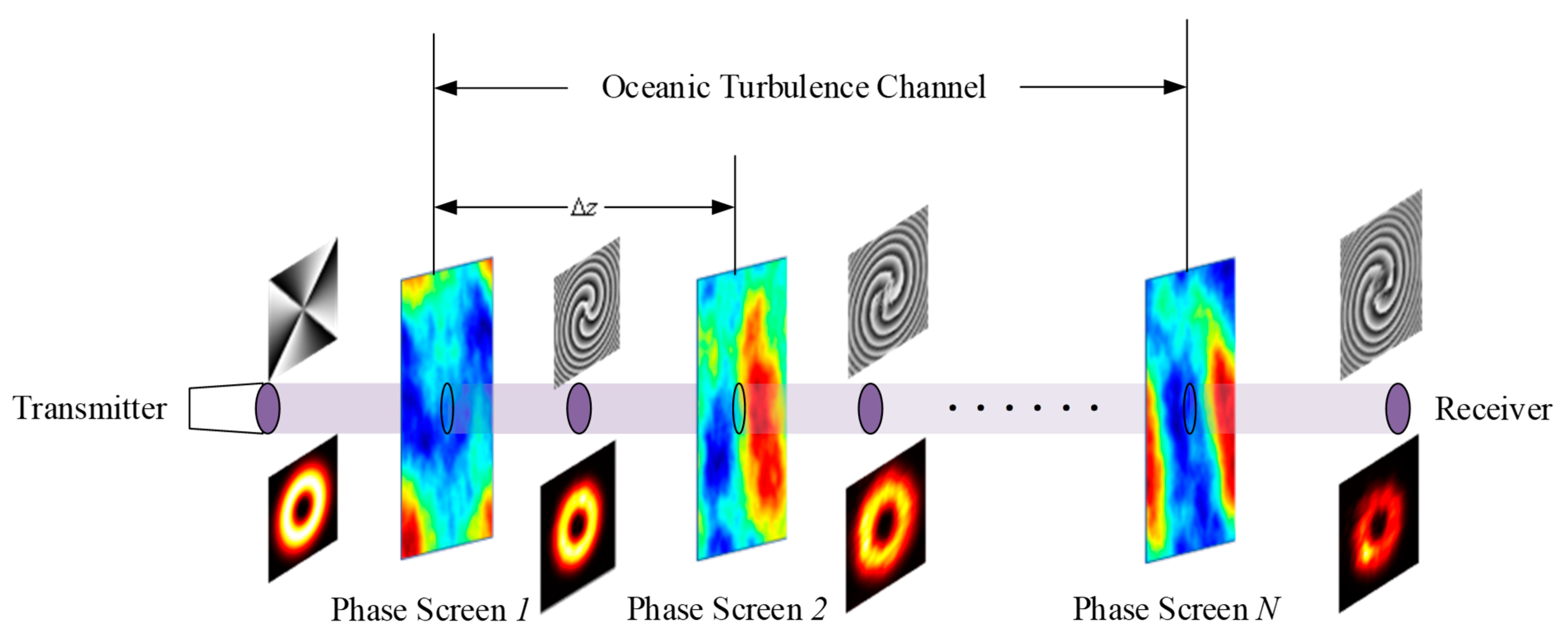
When studying the transmission characteristics of light in ocean turbulence, it is usually necessary to obtain sufficient data under long-distance conditions; however, the light propagation experiments carried out in the ocean require very large human and material resources, and the process is particularly difficult to control. Existing studies have shown that the effect of ocean turbulence on light propagation in free space can be equivalent to the free propagation of light between several random phase screens [
20,
23,
24]. At present, there are three commonly used methods for generating random phase screens: the power spectrum inversion method (Fourier transform method), Zenick polynomial method, and fractal method.
The basic idea of the power spectrum inversion method is to form a complex Gaussian random number matrix with a mean value of 0 and variance of 1 in the frequency domain, and then filter it with the turbulence power spectrum density function. Finally, the inverse Fourier transform is used to obtain the random phase screen. The core idea of the Zernick polynomial method is to decompose the wavefront distortion into the orthogonal Zernick polynomial in the circle domain, and the coefficients of each order polynomial are obtained by the power spectrum function. The fractal method is based on the principle that the distorted wavefront caused by turbulence is a fractal plane, so that the fractal Brownian motion is used to simulate the distorted wavefront caused by turbulence. The method uses the phase structure function and obtains the function value at each point on the random phase screen through interpolation.
The effect of ocean turbulence on optical transmission can be approximately equivalent to the spatial phase disturbance; therefore, multiple random phase screens can be used coaxially to simulate ocean turbulence, in a variety of random phase screen generation methods. The power spectrum inversion method has a fast calculation speed and is suitable for a variety of power spectrum models [
24]. Therefore, this section uses the power spectrum inversion method to generate random phase screens to simulate ocean turbulence channels.
Figure 1 shows the ocean turbulence channel model based on a random phase screen.
Assuming that the random phase screen is perpendicular to the transmission direction of OAM light (that is, the optical axis
), taking the LG beam as an example, in the spatial domain, let the light field of the beam at the light source be
.
is a complex number, the value of the modulo is related to the intensity of the light field, and the angle represents the phase of the light field. Let the spatial frequency domain transfer function of the LG beam propagate in free space as [
25]
Before reaching the first random phase screen, the LG beam is equivalent to transmitting in free space, and the light field when it reaches the first random phase screen is shown in Equation (7):
where
represents the inverse Fourier transform and
represents the Fourier transform. After the LG beam passes through the random phase screen, its light field phase is disturbed and the light field of the LG beam becomes
where
is the random phase screen.
The random phase spectrum of seawater on any slice perpendicular to the optical axis
is
Furthermore, the spectral variance of the ocean turbulence stochastic phase screen can be obtained as
Among them,
is the grid size of the ocean turbulence random phase screen and
is the dimension of the complex matrix, which can be obtained by two-dimensional Fourier transform:
where
is a matrix of complex random numbers with a dimensional mean of 0 and a variance of 1.
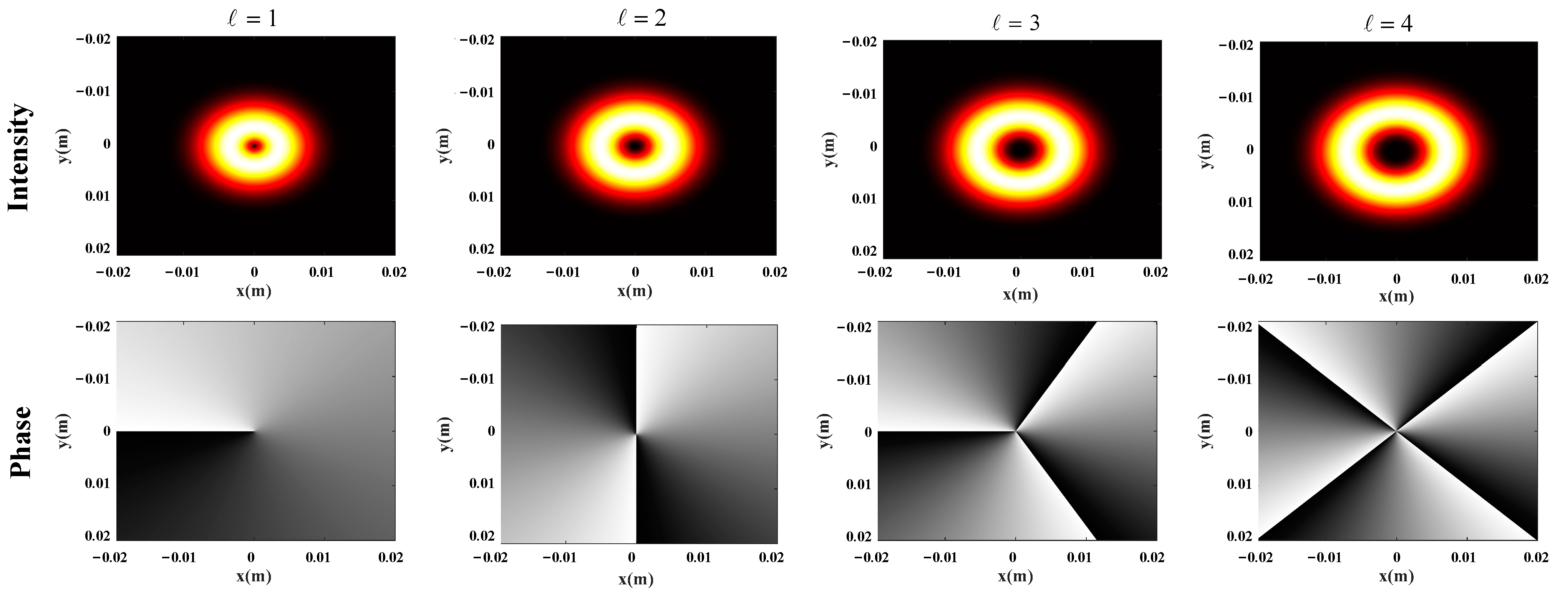
The intensity and phase distribution of a typical LG beam is shown in
Figure 2, which describes the intensity and phase distribution of the LG beam with modal values at the source. As can be seen from the figure, LG beam has annular intensity distribution and spiral phase distribution. When the mode value
increases, the annular distribution increases and the phase changes around the optical axis.Because the phase distribution of two LG beams with different topologies and values has obvious orthogonal characteristics, OAM light can often be used as a dimension resource for encoding in UWOC.
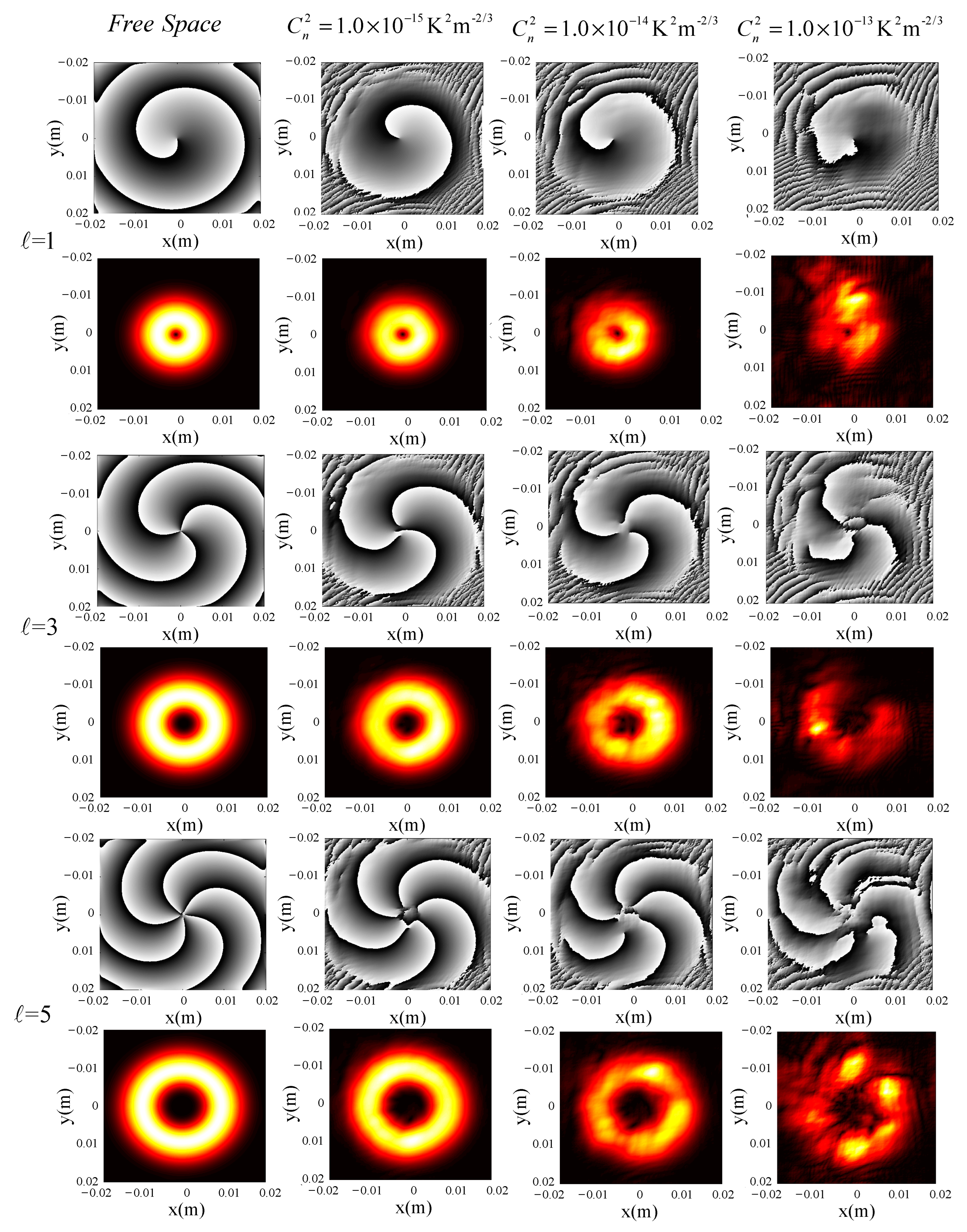
Figure 3 shows the spatial distribution of the LG beam (
) at different values of
(
,
, and
) when
. When
, it is obvious that both the intensity and phase distribution maintain quite good integrity and the phase dividing line of the phase distribution is obvious. When
, the integrity damage of LG beam intensity and phase distribution is very obvious and the helical boundary of the phase distribution is no longer smooth. When
, the intensity distribution of the LG beam only retains partial annular distribution, the helical phase boundary of phase distribution shows obvious irregular jitter, and the distortion degree around the central singularity is significantly increased. In conclusion, OAM with a smaller
value has stronger resistance to turbulence interference, which has also been verified by simulation through the support vector machine in a previous paper [
26].
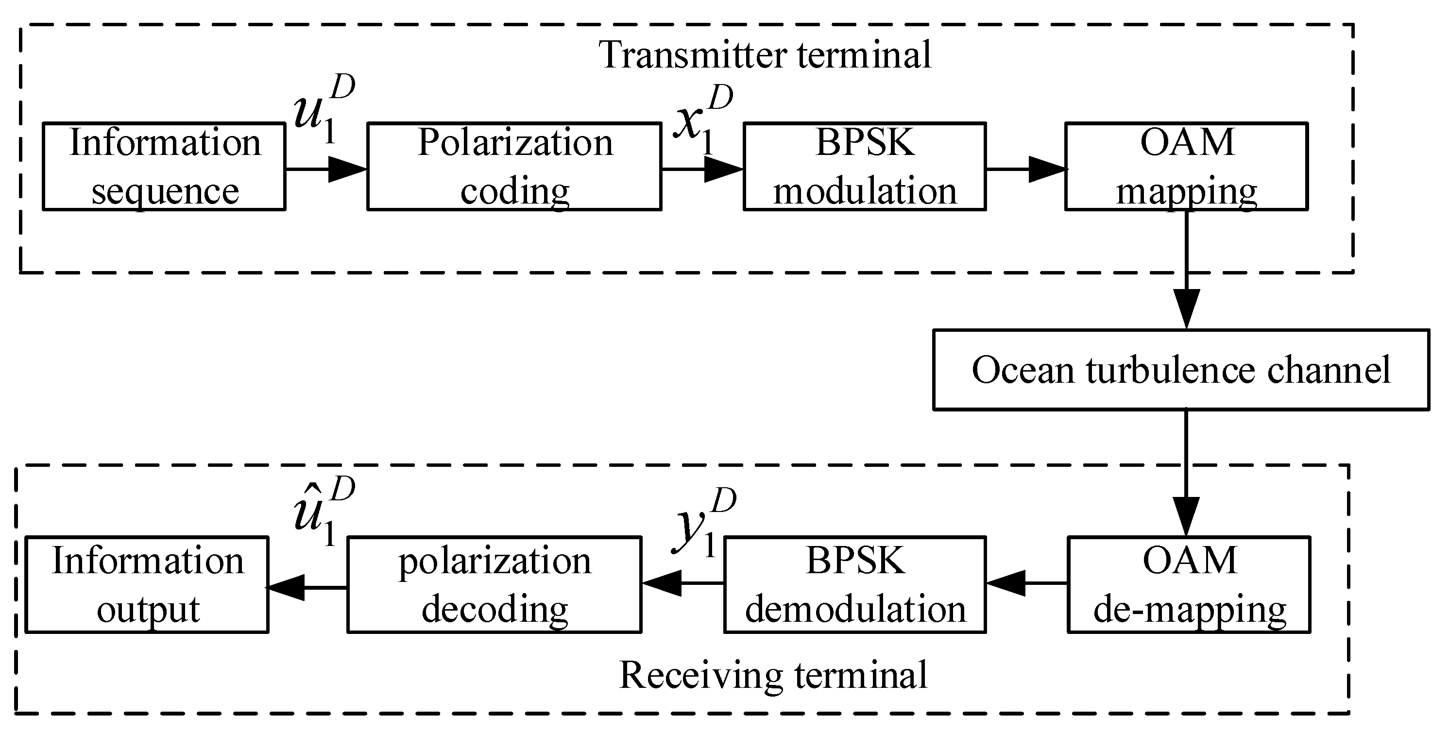
According to the spatial distribution of OAM and the performance of different modes of OAM in ocean turbulence, we determined the system block diagram, as shown in
Figure 4. BPSK modulation technology is used as the modulation module, because, compared with QPSK and 8PSK, BPSK has a lower transmission efficiency but stronger anti-noise performance. The modulated signal cannot be transmitted directly in the ocean turbulence, so the OAM mapping module is used to map the modulated signal to the OAM mode. In the text, the OAM of
= 1 represents the modulated symbol “1” and the OAM of
= −1 represents the modulated symbol “−1”. The OAM de-mapping module is used to recover the signal from the received OAM light.
3. Channel Coding Technology
Turbo code, also known as parallel cascaded convolutional code, has two component code decoders, and the decoding is iteratively decoded between the two component decoders, so the whole decoding process is similar to turbine work [
27,
28]. Turbo code can bring the efficiency of channel coding close to the Shannon limit and be used as the coding technology in 3G/4G mobile communication. Because Turbo code adopts iterative decoding, it is difficult for it to meet the needs of ultra-high speed and ultra-low latency 5G scenarios where real-time performance requirements are very high.
The check matrix of LDPC code has the characteristic of sparsity, which makes its coding and iterative decoding algorithm less complex and easier to implement in hardware and, compared with other coding methods, the code rate composition of LDPC code is flexible, with lower error leveling. When the code length is long enough, the information transmission rate of the communication system can approach the Shannon limit [
29,
30].
Both Turbo codes and LDPC codes have certain randomness during construction, such as constructing an interleaver for Turbo code and the node distribution design of LDPC codes. Therefore, when designing a specific coding scheme, it is necessary to carry out code structure traversal or heuristic construction according to design parameters. This random construction makes it difficult for the final encoding scheme of a finite code length to achieve the theoretical optimal performance.
Professor Erdal Arikan [
31] proposed polarization code for the first time in 2008, which was the first channel coding technology that could theoretically reach Shannon’s theoretical limit. Because of the low complexity of encoding and decoding of polarization codes, the performance of polarization codes is very good in the case of long codes, and the performance is improved with the increase in code length. When the code length goes to infinity, the channel polarization can be completely carried out, that is, only the perfect channel and the full noise channel exist.
Common construction methods of Polar codes include the Barcanalis parameter construction, Gaussian approximation construction, evolutionary degradation construction, and Monte Carlo construction. The Barcanalis parameter construction method is applied only to binary deletion channels. Suppose that the code length is D. When the channel index is between 0 and 0.5D, the channel capacity of most molecular channels tends to “0”. When the channel index is between 0.5D-D, the channel capacity of most molecular channels tends to “1”. When the channel index is near 0.5D, the channel capacity of the corresponding sub-channel is uncertain. The Gaussian approximation construction method is applied to the Gaussian channel. When the channel index is small, the expected value of the logarithmic likelihood ratio is also small. When the channel index is large, the expected value of the logarithmic likelihood ratio is also large. When the channel index is in the middle, the expected value of the logarithmic likelihood ratio of the corresponding channel increases in a stepped trend. Professor Erdal Arikan [
31] introduced the principle of Polar code compilation in detail in his own paper, which will not be repeated in this article. Next, the channel polarization method of ocean turbulence channels will be introduced.
The degenerate construction method is only suitable for binary symmetric input channels, while ocean turbulence channels have a more complex channel environment, thus these three construction methods are not suitable. The Monte Carlo construction method is more suitable for ocean turbulence channels because of its universality. The Monte Carlo construction method is a more commonly used method in mathematical statistics. In polarization channel information bit selection, the error probability of each subchannel can be calculated by a large number of simulations, according to the bit error rate of the subchannel in order from smallest to largest. For the code length D, with code rate D/K polarization coding, the first K channels transmit information bits, and D-K subchannels place frozen bits.
The Monte Carlo construction method requires a complete process of Polar coding and decoding. The difference is that, in the Monte Carlo construction method, the step of selecting information bits is placed last and, at the beginning, all subchannels place frozen bits. Decoding adopts relatively simple but more effective successive elimination decoding (SC decoding), which is slightly different from the decoding step; in the Monte Carlo construction method, only the bits that currently need to be decoded are unknown and the others can be used as known bits, so that a series of errors will not occur because of a bit decoding error. Next, the calculated logarithmic ratio of likelihood is decoded by hard judgment and compared with the frozen bit to calculate its error probability.
As the encoding matrix and decoding are independent of the channel, the Monte Carlo construction method can be applied to the selection of any channel information bit. Assuming the code length is D, the channel parameters of the polarizer subchannel can be used, as shown in Equation (12).
where
is the sampling of the joint probability distribution
. In the Monte Carlo method, the corresponding mean is
.
The steps to construct the Polar code are as follows:
(1) Generate a 0-bit sequence with length D and multiply the generation matrix to obtain the polarization coder ;
(2) Send into the channel to obtain the receiving codeword at the receiving end;
(3) Use Equation (12) to calculate the likelihood ratio in the initial channel for each bit in ;
(4) Use SC decoding to calculate the sending information of each subchannel;
(5) Count the bit error rate of each subchannel, then select K subchannels with a low bit error rate for transmitting information bits, and use the remaining D-K channels to transmit freezing bits.
4. Analysis of Simulation Results
This section first analyzes the bit error rate performance of the OAM optical communication system with and without polarization coding when and , and then analyzes the bit error rate performance of different decoding algorithms with different values ( and ) and different values (, , and ).
Figure 5 shows the comparison of bit error rate performance with and without channel coding under the condition of weak ocean turbulence. As can be seen from the figure, in the absence of channel coding, the bit error rate performance of the system deteriorates rapidly with the increase in transmission distance, which seriously affects the communication performance. However, in the case of channel coding, the bit error rate performance of the system is improved to a considerable extent. The bit error rate at 30 m is reduced from 0.435 to 0.209. Although the system bit error rate is still high, the bit error rate performance can continue to be optimized by other means.
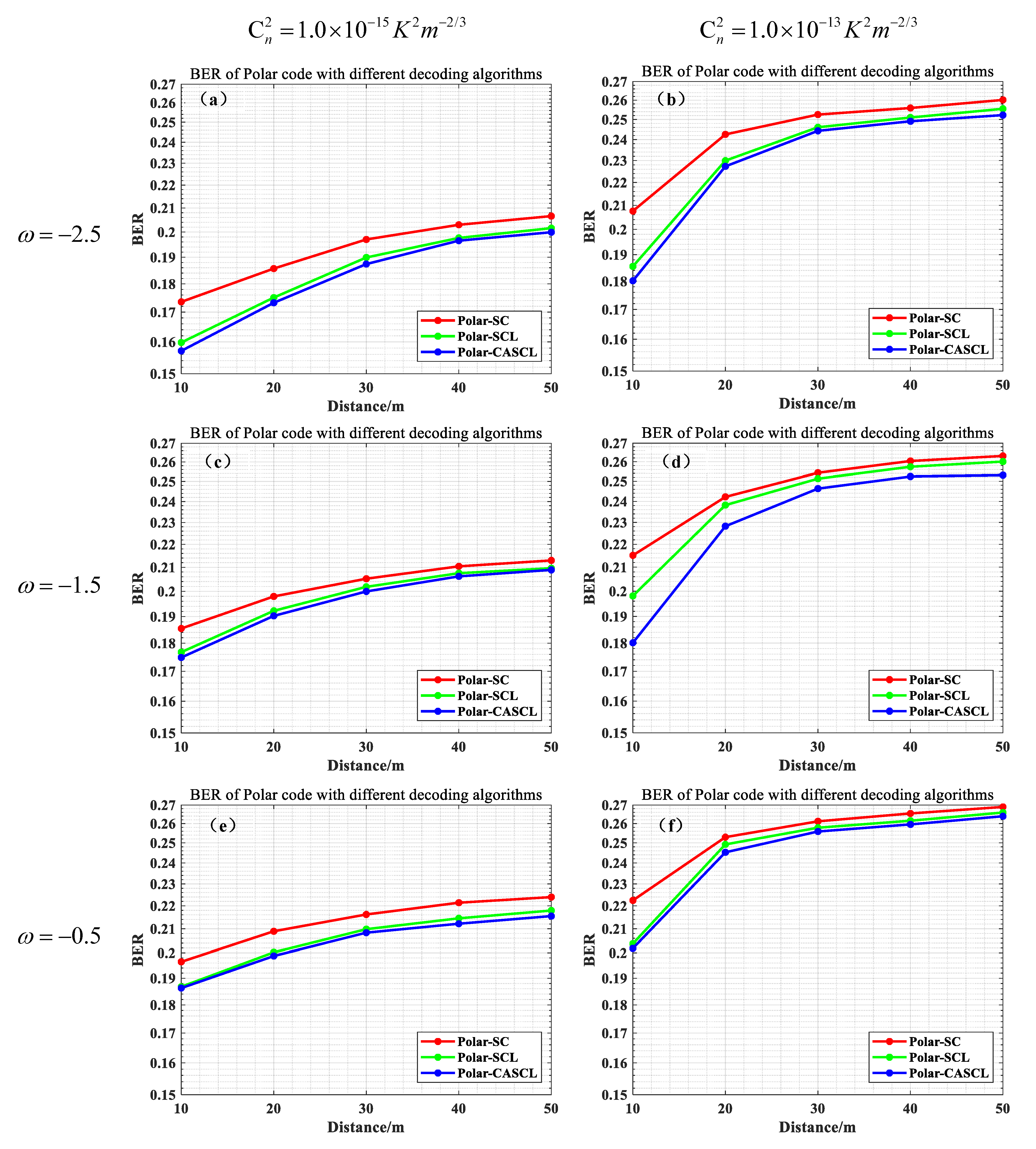
Figure 6 shows the bit error rate performance of different decoding algorithms (SC, SCR, and CASCL) under different turbulence intensities (
and
) and different ratios of ocean turbulence due to salinity to ocean turbulence due to temperature (
,
, and
). The transmission distance is 50 m, the phase screen is spaced at an interval of 10 m, the phase screen size is 0.04 m × 0.04 m, the selected beam wavelength is 532 nm, the girdle radius is 0.005 m, the yard length D = 512, the modulation method is BPSK, and the decoding result requires 50 iterations to obtain the average.
Generally speaking, in the ocean turbulence channel, with the increase in the value of , three different decoding methods are seriously affected by turbulence and the bit error rate increases accordingly; further, the greater the turbulence intensity, the higher the bit error rate of the three decoding methods. The bit error rate of the system increases with the increase in transmission distance and sum. The best decoding performance is CASCL, while the performance of the SCL decoding algorithm has little difference from the CASCL decoding algorithm, and the worst performance is found for the SC decoding algorithm. The reason for this situation is that the SCL decoding algorithm and CASCL decoding algorithm consider multiple paths when making a judgment, instead of choosing only the path with the highest metric value for downward expansion, as the SC algorithm does.


