
Influence of Auxiliary Pipelines of the Deepwater Drilling Riser on the Dynamic Characteristics of the Subsea Wellhead


Abstract
:1. Introduction
2. Mechanical Model
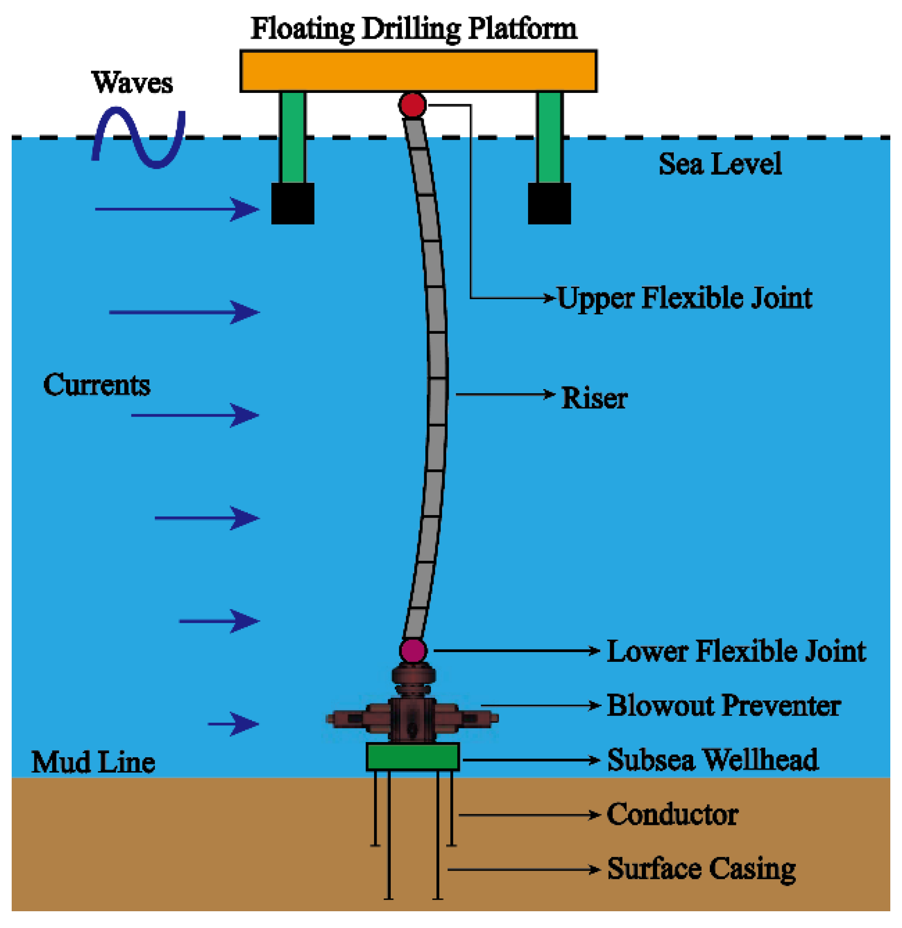
2.1. Mechanical Model of the Floating Platform–Riser–BOP–Subsea Wellhead
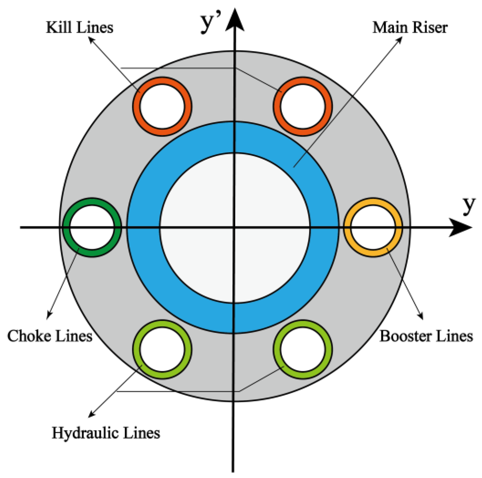
2.2. Model of the Auxiliary Pipelines
2.3. Marine Environmental Loads and Platform Motion
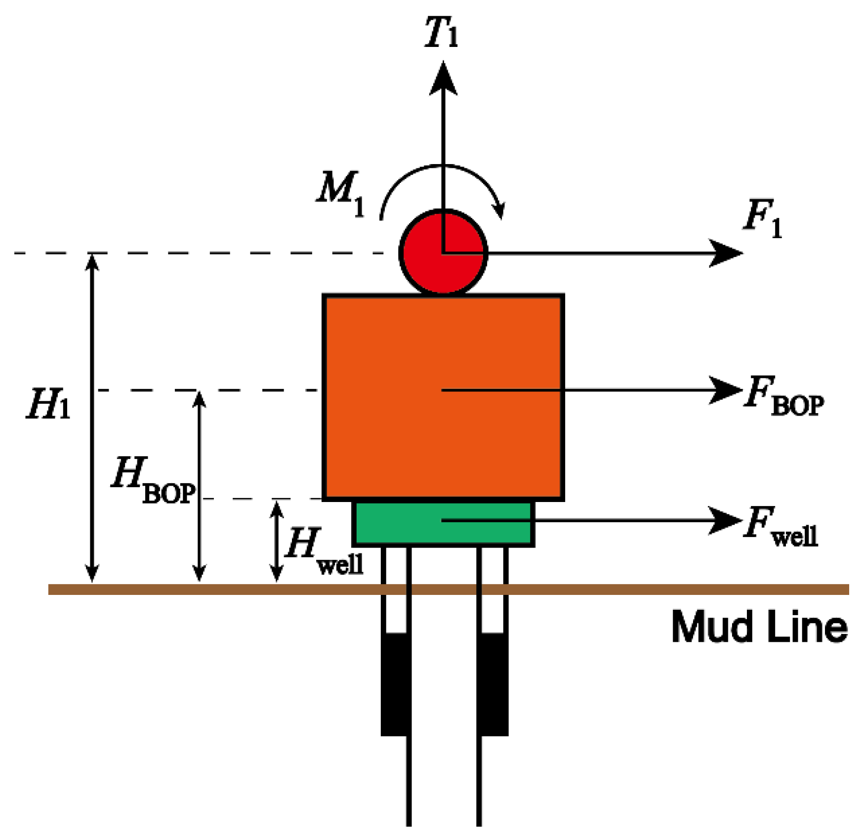
2.4. Mechanical Model of the Subsea Wellhead
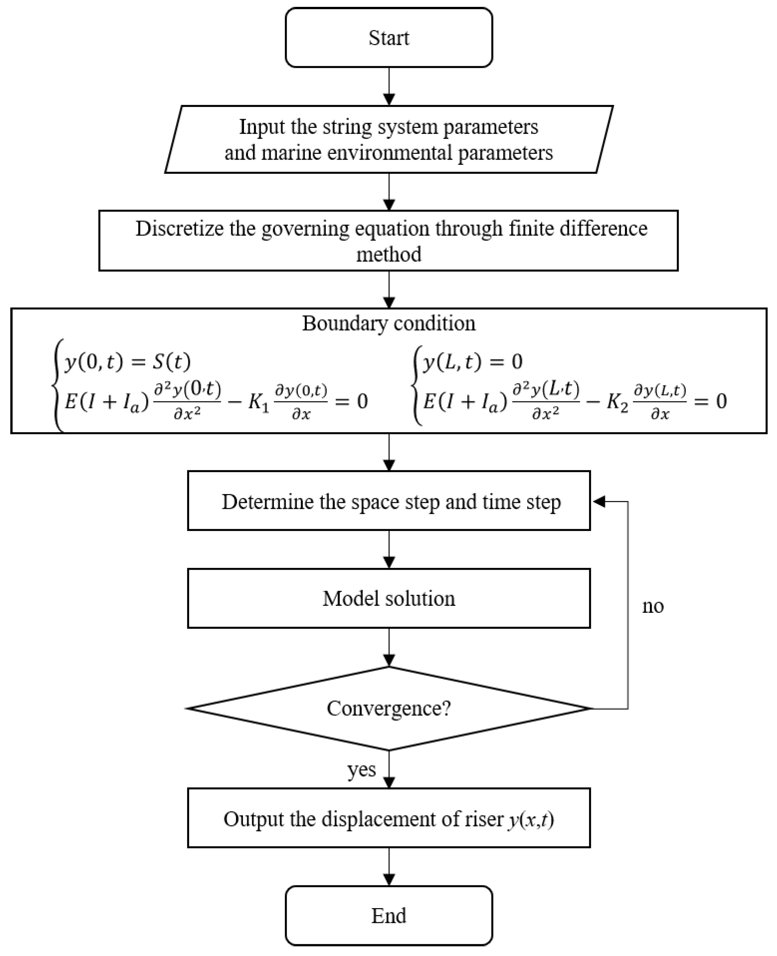
3. Model Solution
4. Case Study
4.1. Case Study
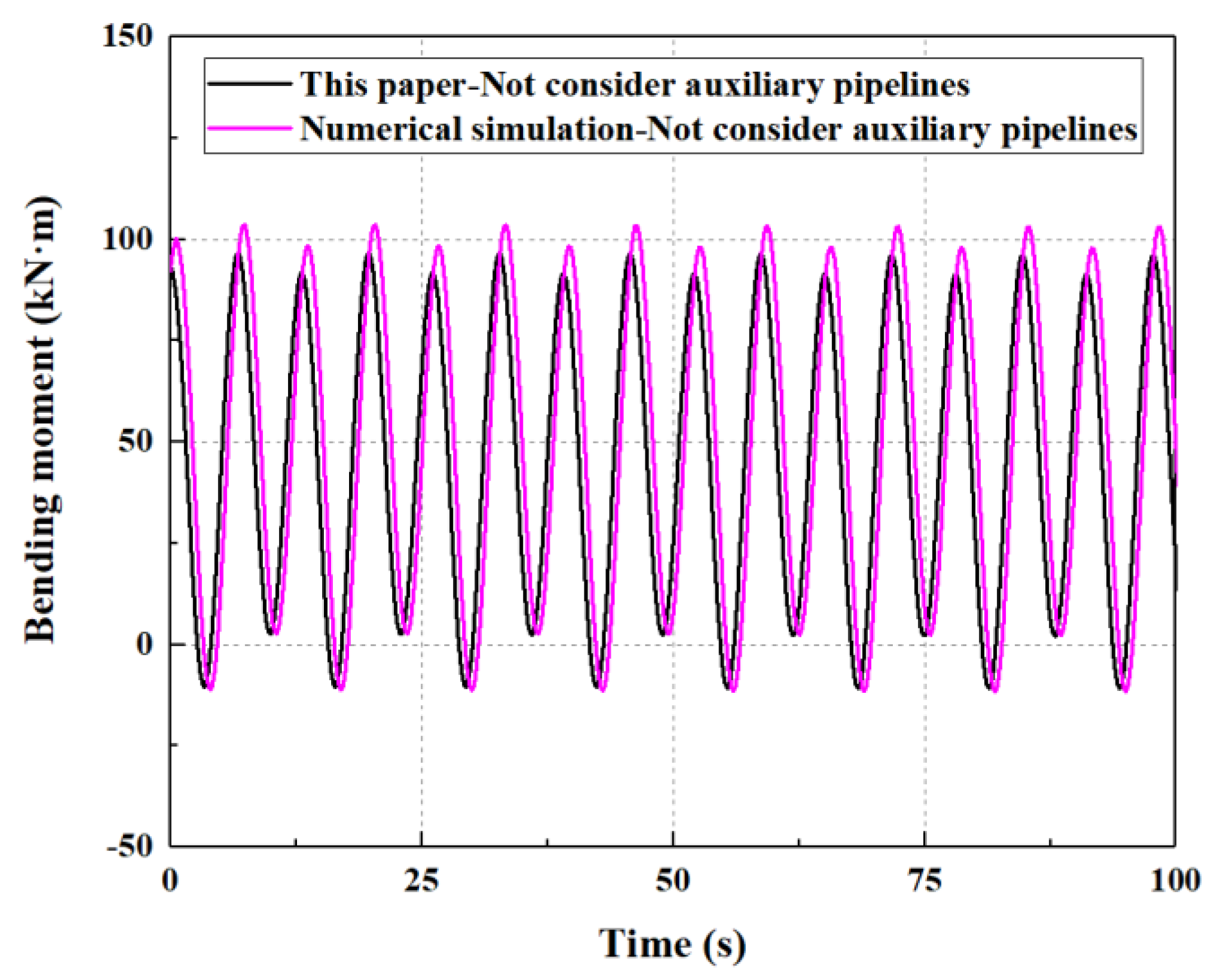
4.1.1. Model Validation
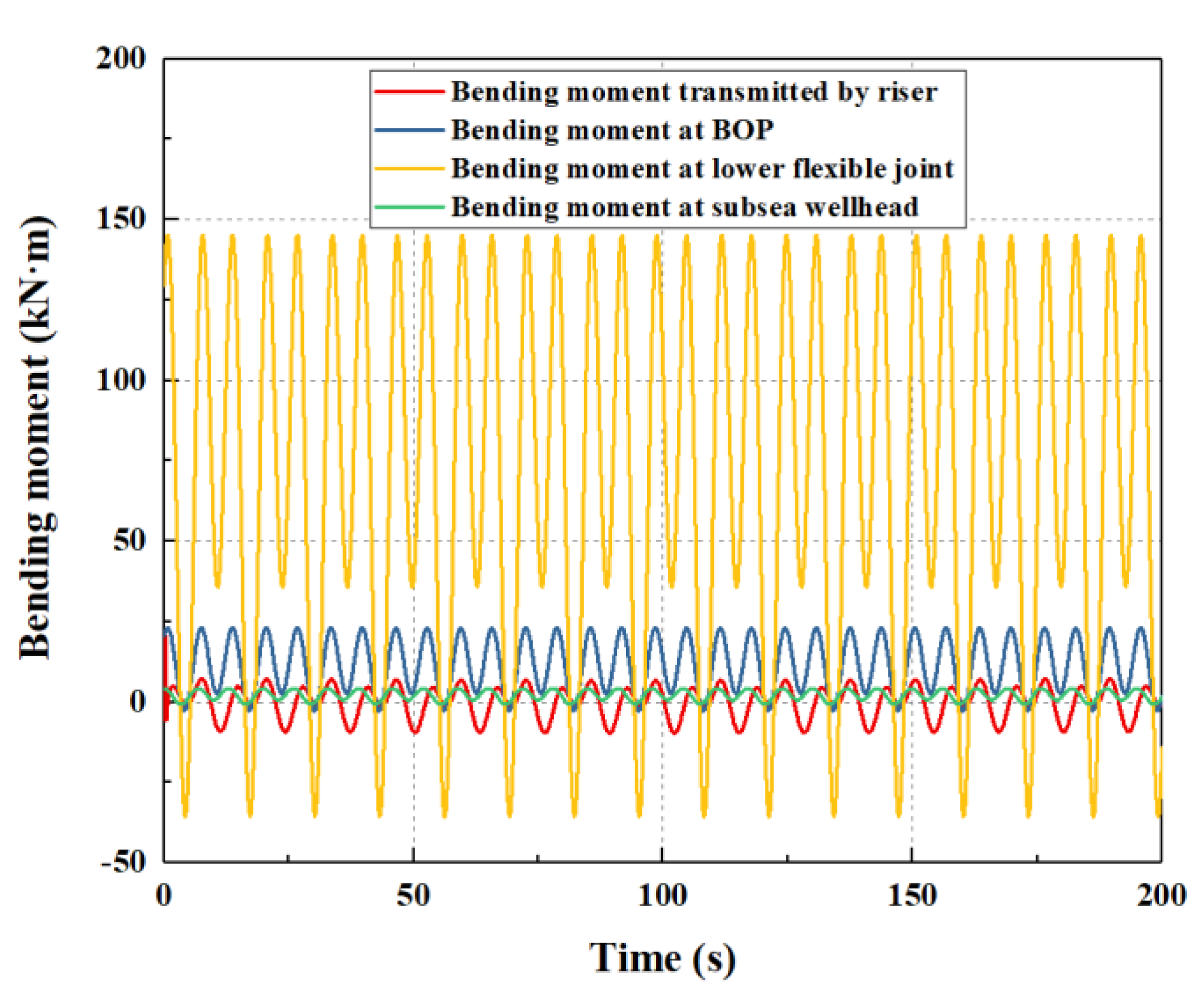
4.1.2. Results of the Case Study
4.2. Sensitivity Analysis
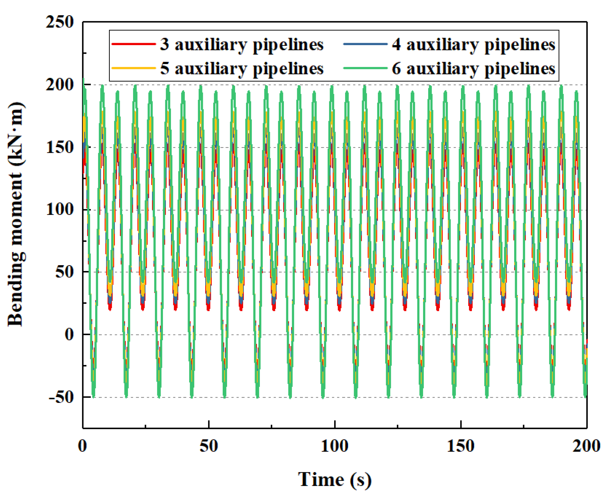
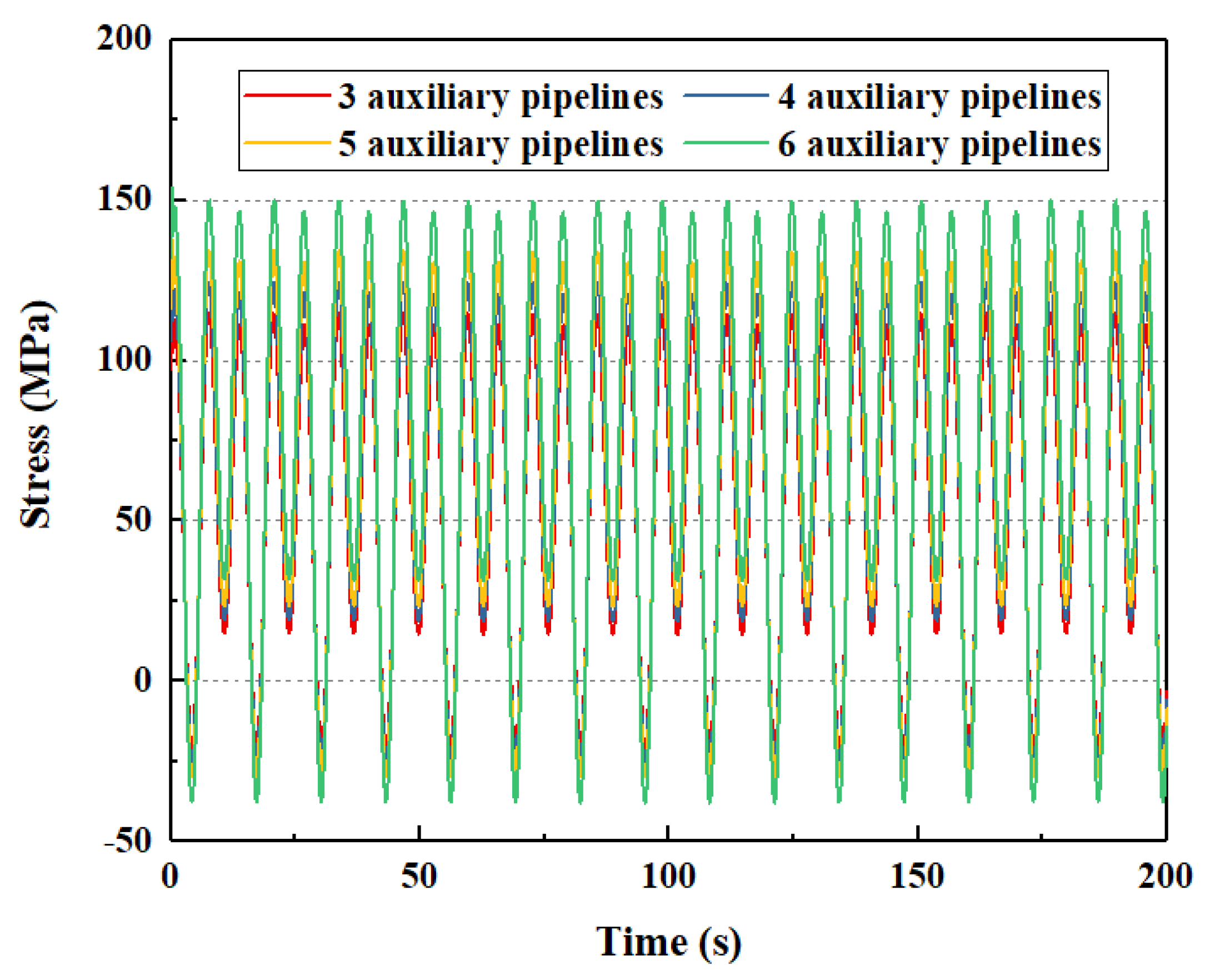
4.2.1. Auxiliary Pipelines
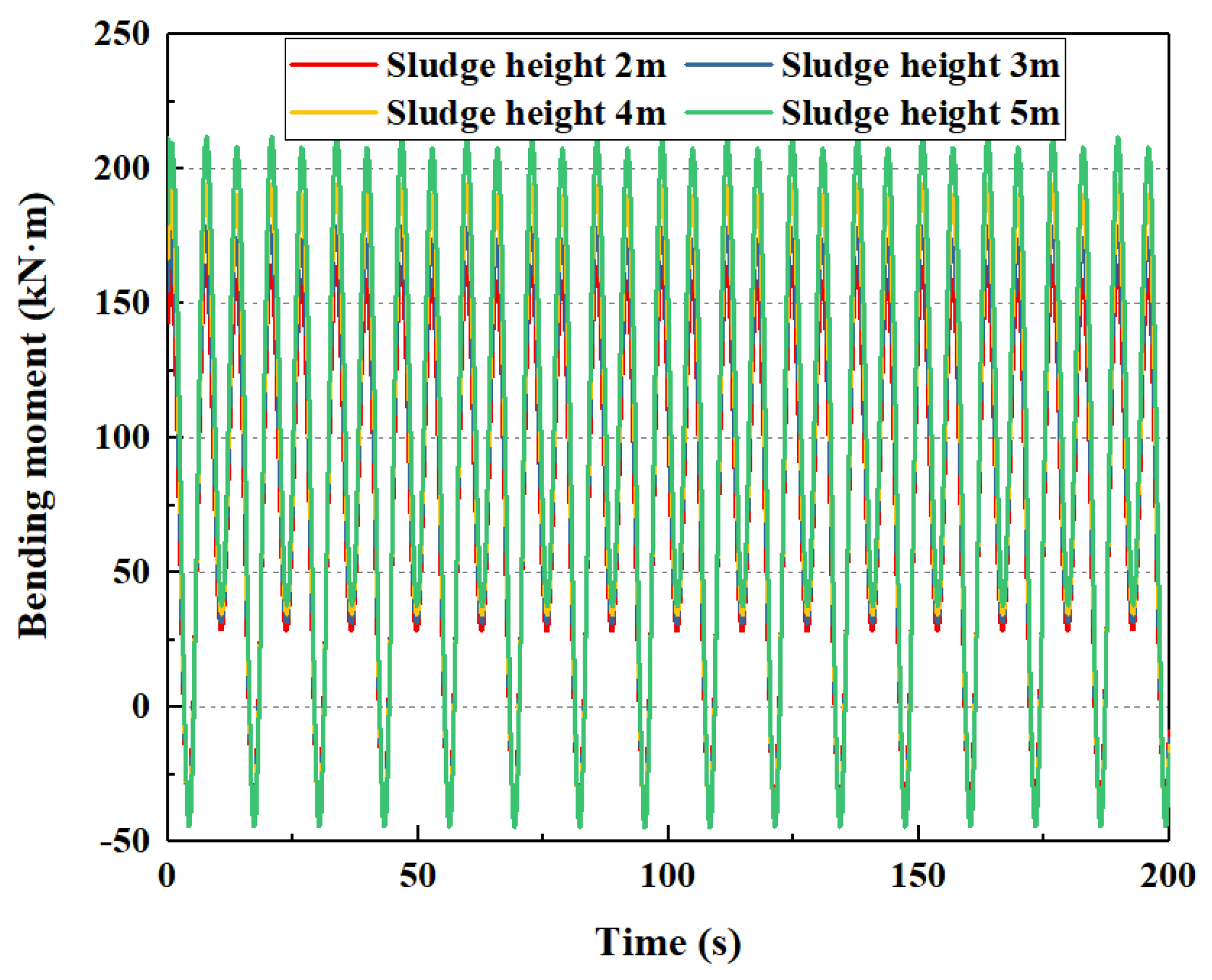
4.2.2. Sludge Height of the Subsea Wellhead
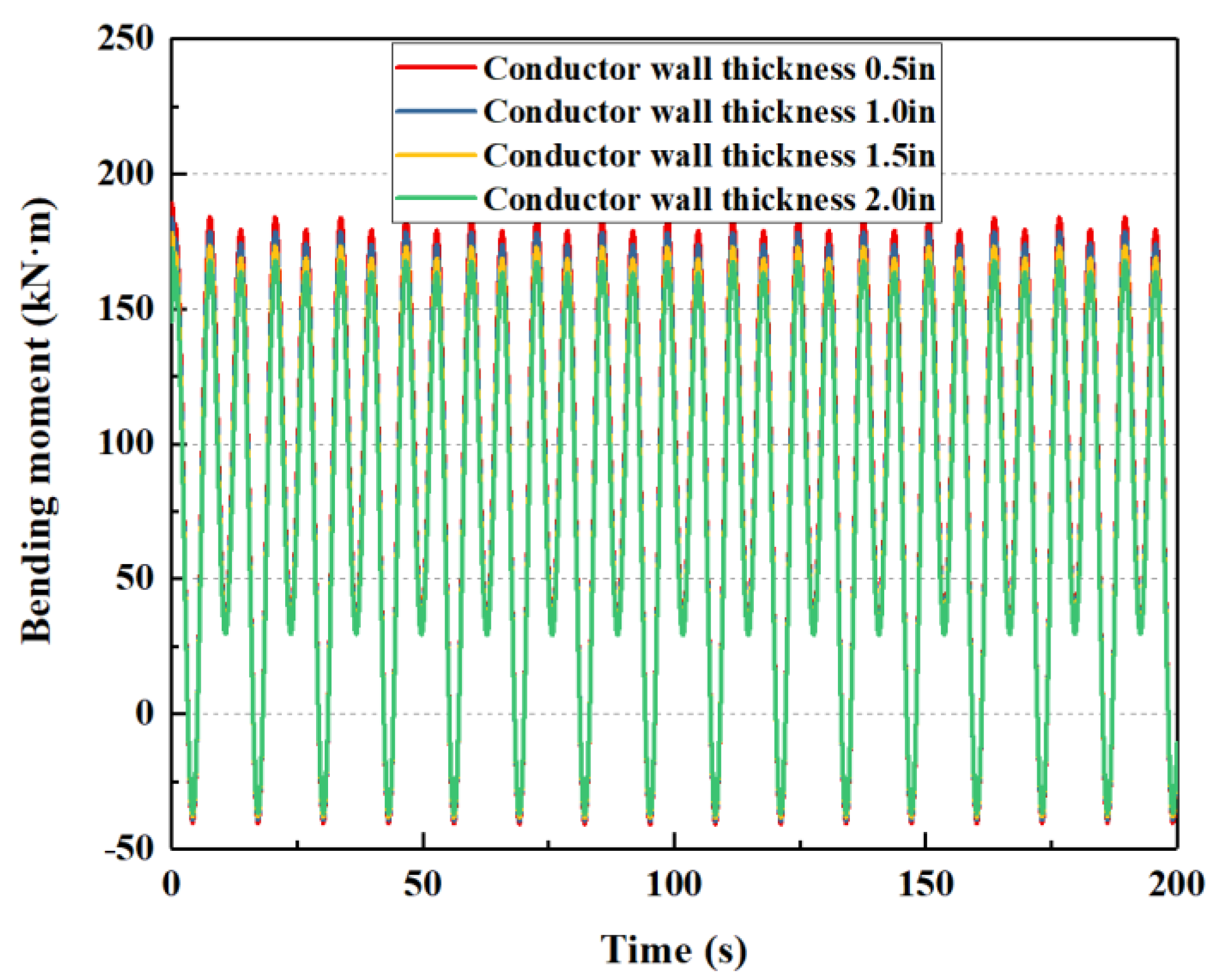
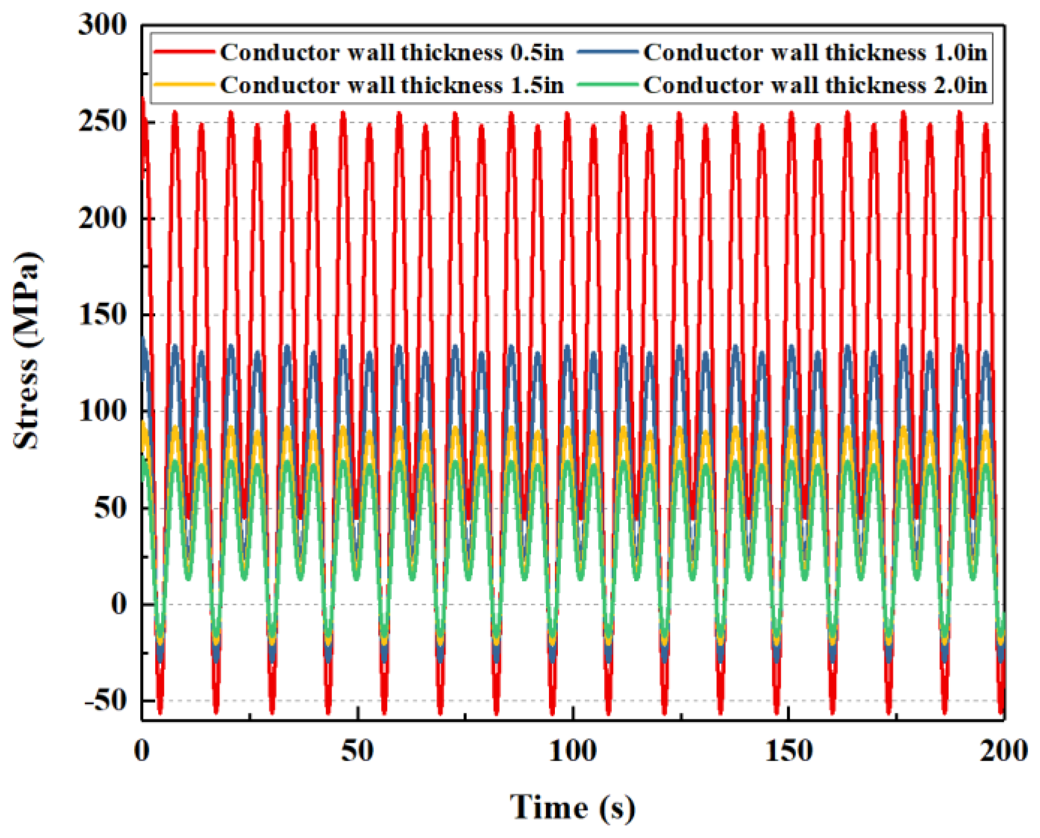
4.2.3. Wall Thickness of the Conductor
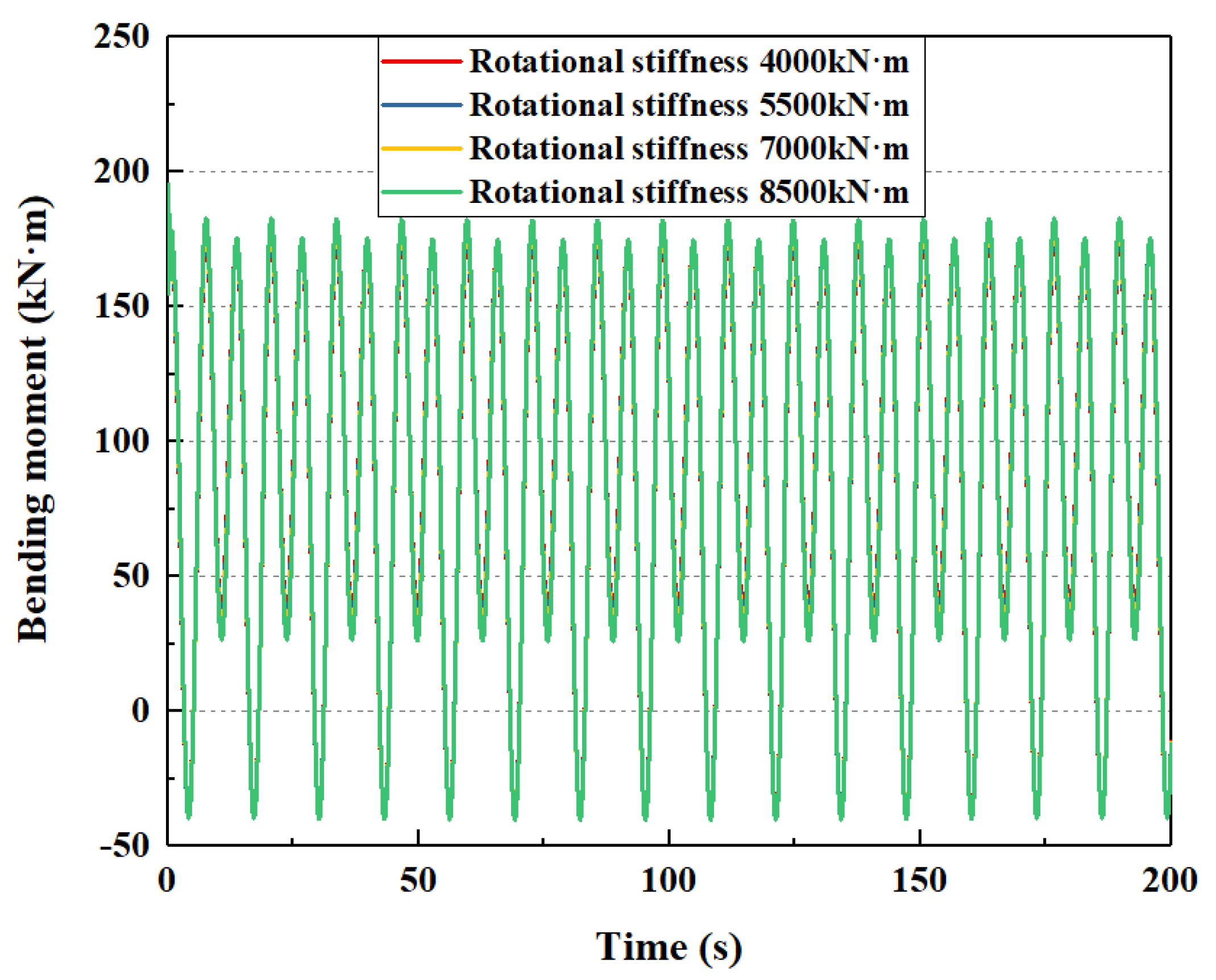
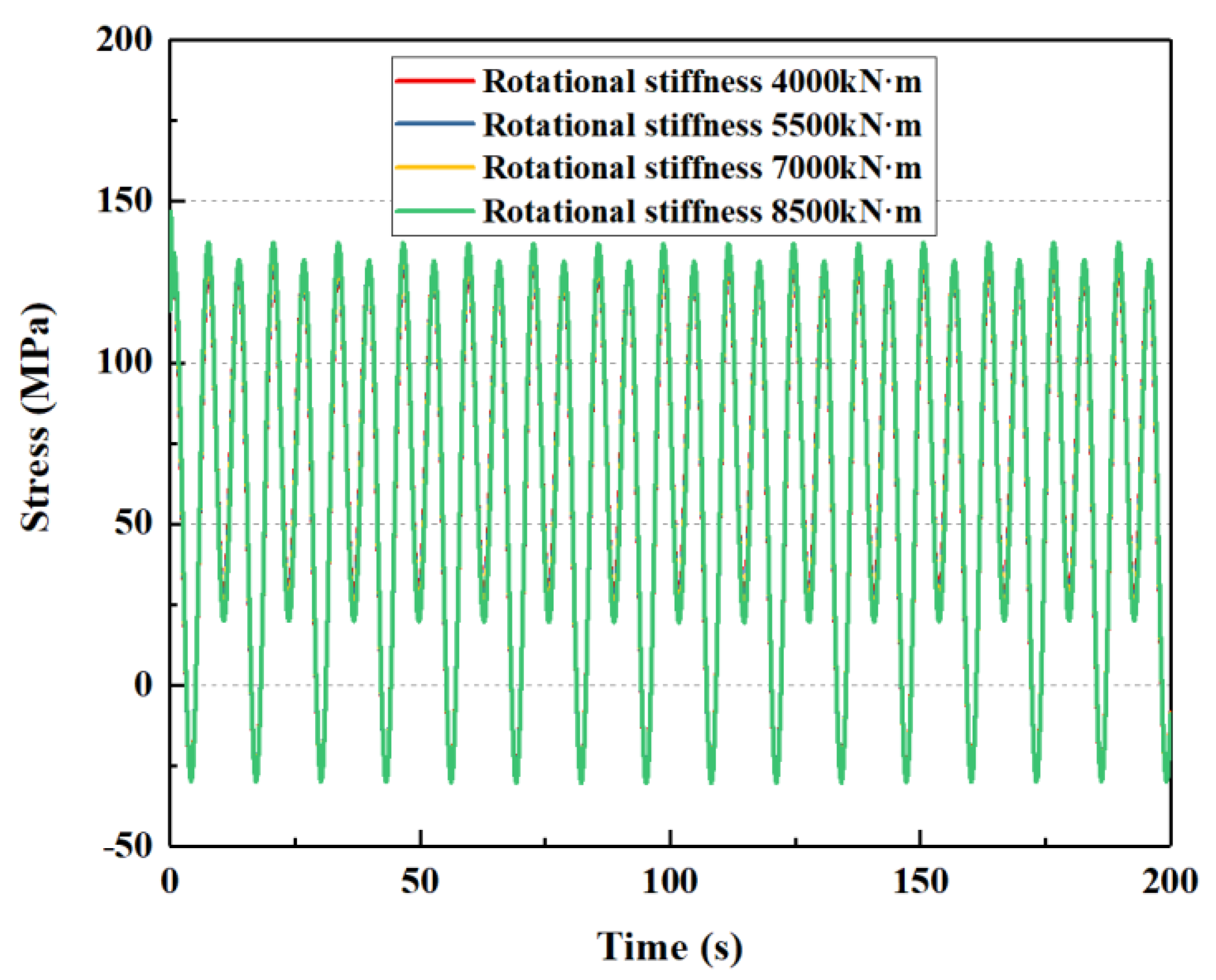
4.2.4. Rotational Stiffness of the Lower Flexible Joint
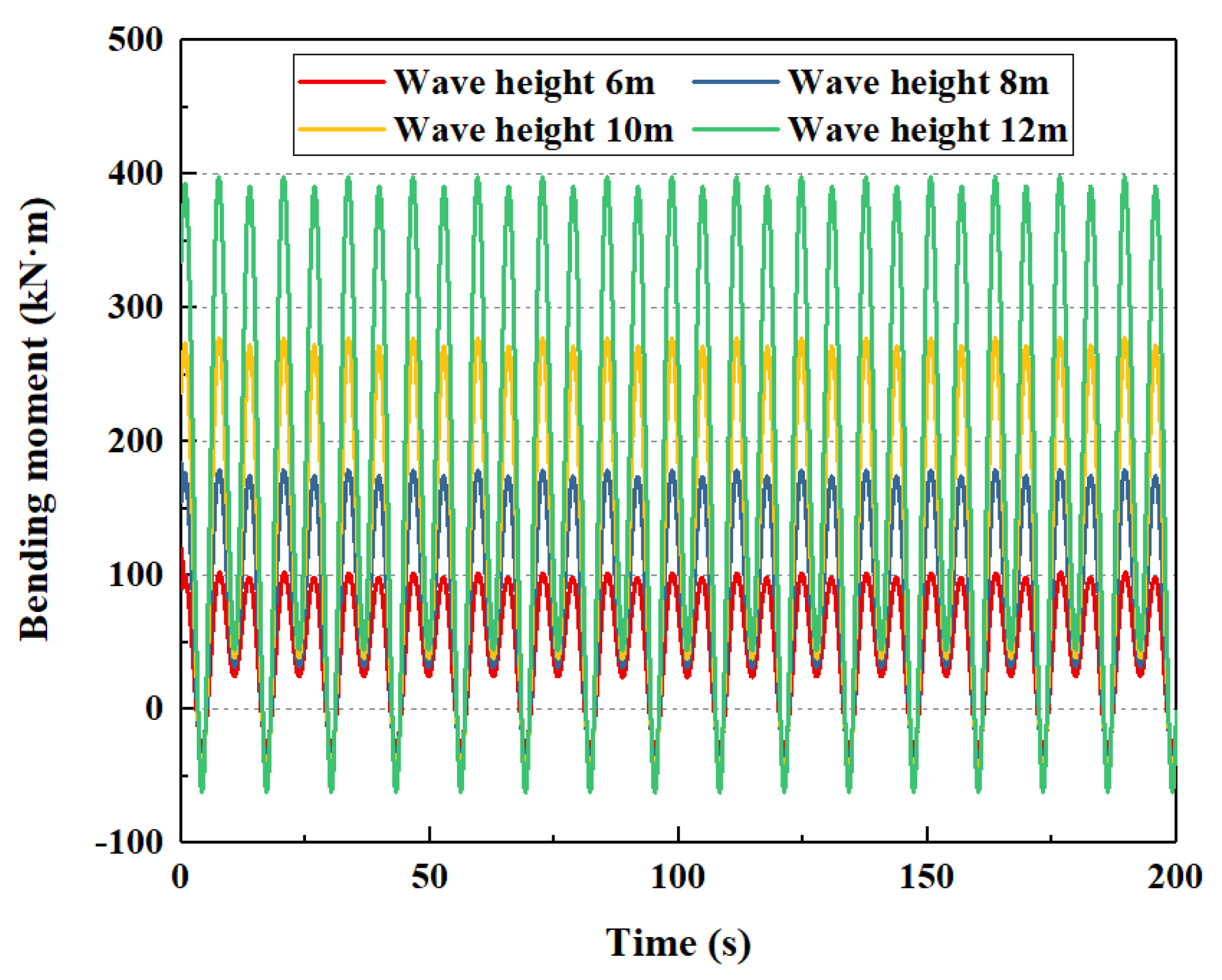
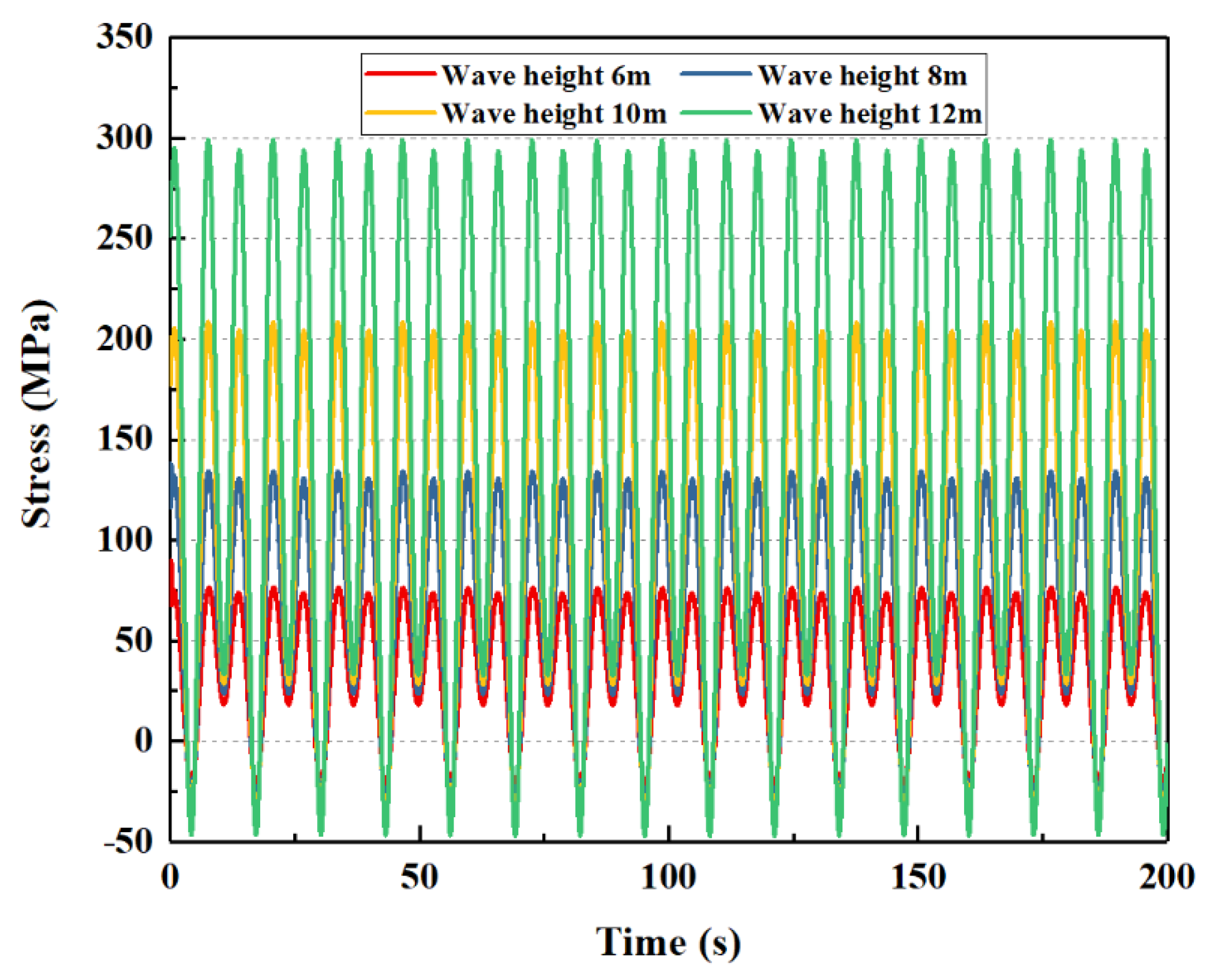
4.2.5. Wave Height
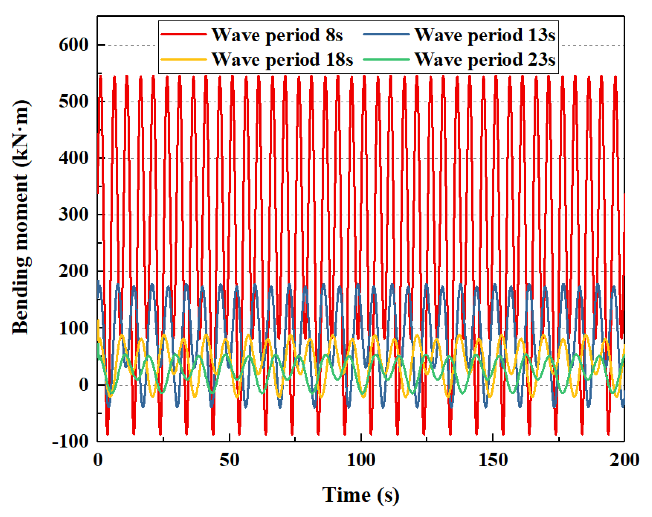
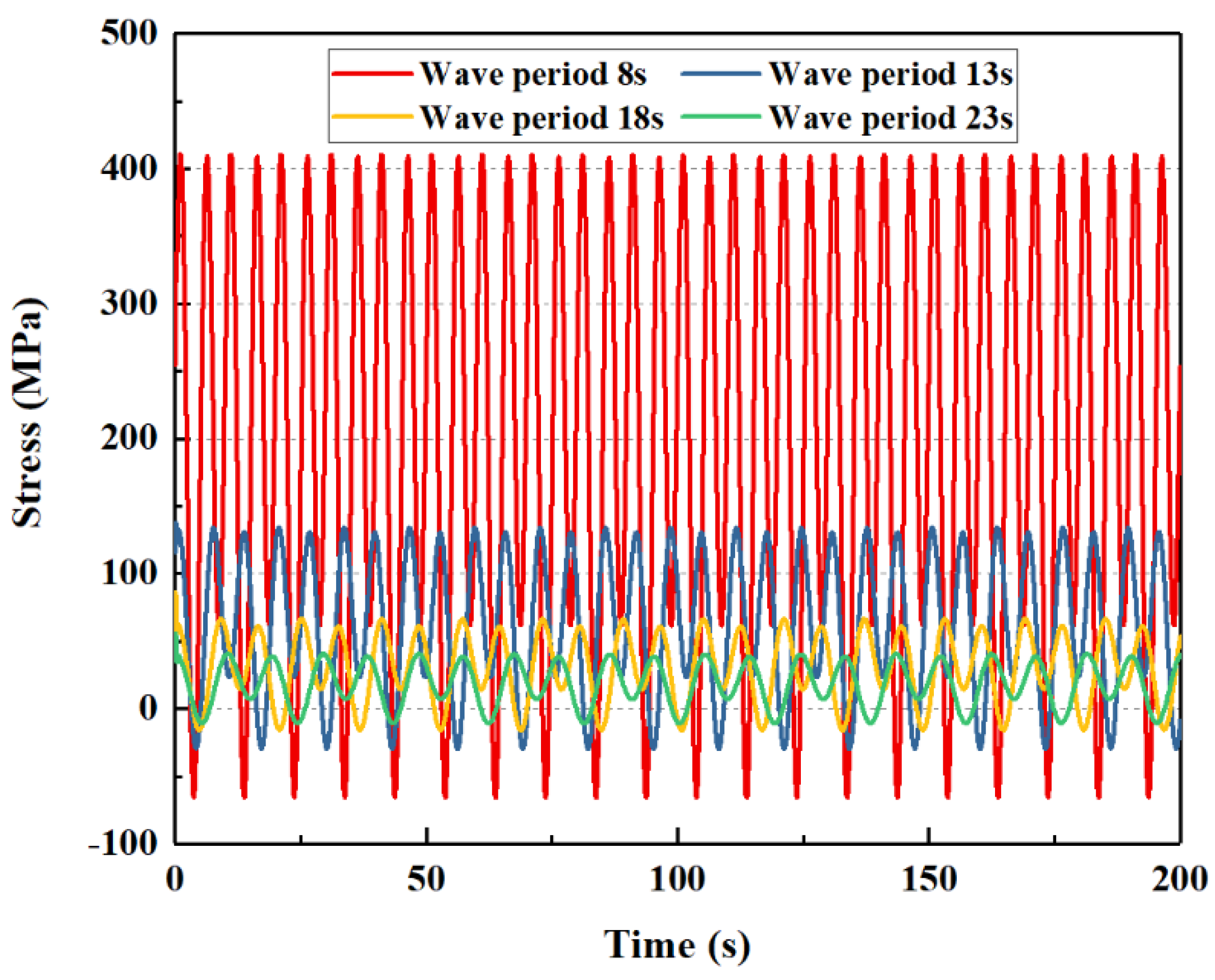
4.2.6. Wave Period
4.3. Orthogonal Experiment
5. Discussion
- (1)
- The mechanical model and analysis method of the dynamic response of the subsea wellhead have been established, considering the auxiliary pipelines and floating drilling platform. The model is verified by numerical simulation. The dynamic bending moment and stress of the subsea wellhead have been obtained;
- (2)
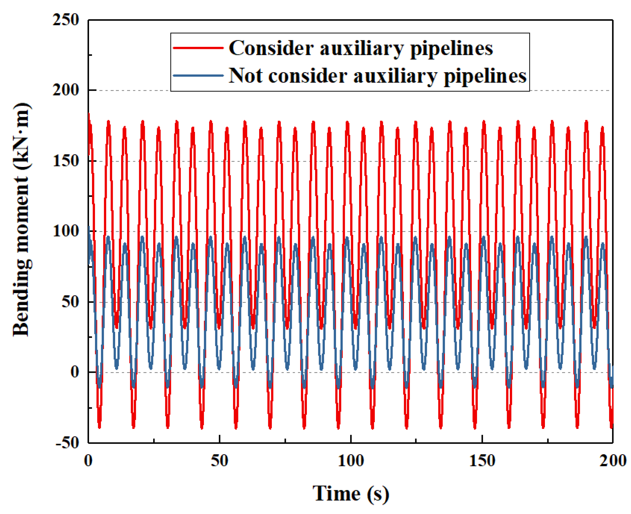
- The auxiliary pipelines have an important influence on the dynamic characteristics of the subsea wellhead. If the auxiliary pipelines are considered, the bending moment and stress on the subsea wellhead are significantly increased. Therefore, this study suggests that the auxiliary pipelines should be considered in the dynamic analysis of the subsea wellhead to obtain a more realistic dynamic response of the subsea wellhead;
- (3)
- Wave period is the most important factor affecting the mechanical behavior of the subsea wellhead. Wave height, wall thickness of the conductor, and sludge height are secondary factors affecting the mechanical behavior of the subsea wellhead. The rotational stiffness of the lower flexible joint has little influence on the mechanical behavior of the subsea wellhead.
6. Conclusions
- (1)
- The contribution of this paper is to optimize the entire mechanical model of the floating platform–riser–BOP–subsea wellhead by considering the effect of auxiliary pipelines on the riser. Furthermore, the more accurate bending moment and stress transmitted to the subsea wellhead have been obtained. Comparing the theoretical calculation results with the numerical simulation results, the calculation accuracy is 93.3%. Subsequently, through sensitivity analysis and orthogonal experiments, the influence factors of the mechanical characteristics of the subsea wellhead have been discussed, and the main controlling factors affecting the mechanical characteristics of the subsea wellhead have been obtained;
- (2)
- In the future, in order to further verify the reliability of the theoretical model, indoor testing or ocean tests can be carried out subsequently to obtain real subsea wellhead mechanical-response results. By comparing the test results with the theoretical calculation results, the confidence of the theoretical model can be increased;
- (3)
- This research can lay the foundation for developing independent mechanical analysis software for the deepwater subsea wellhead system, and ultimately achieve application in deepwater drilling engineering.
Author Contributions
Funding
Institutional Review Board Statement
Informed Consent Statement
Data Availability Statement
Acknowledgments
Conflicts of Interest
Nomenclature
| BOP | Blowout preventer |
| E | Elastic modulus of the riser, Pa |
| I | Inertia moment of the riser, m4 |
| y(x,t) | Lateral displacement of the riser, m |
| x | Axial length of the riser, m |
| f(x,t) | Wave current force on the riser, N/m |
| T(x) | Axial tension of the riser per length, N/m |
| M | Total weight of the riser per length, kg/m |
| S(t) | Dynamic motion of the floating platform, m |
| K1 | Rotational stiffness of the upper flexible joint, N·m/rad |
| K2 | Rotational stiffness of the lower flexible joint, N·m/rad |
| L | Riser length, m |
| Ws | Weight of the riser in seawater, N |
| fwt | Submersion coefficient, which is 1.05 in this paper |
| Bn | Buoyancy force of the buoyancy joint, N |
| fbt | Effective coefficient, which is 0.96 in this paper |
| Ai | Area of the riser inner diameter, m2 |
| ρm | Density of the drilling fluid, kg/m3 |
| ρw | Density of seawater, kg/m3 |
| Ia | Inertia moment of the riser auxiliary pipelines, m4 |
| ma | Weight of the auxiliary pipelines per length, kg/m |
| a | Number of kill lines, dimensionless |
| D1 | Outer diameter of the kill lines, m |
| d1 | Inner diameter of the kill lines, m |
| b | Number of hydraulic lines, dimensionless |
| D2 | Outer diameter of the hydraulic lines, m |
| d2 | Inner diameter of the hydraulic lines, m |
| c | Number of choke lines, dimensionless |
| D3 | Outer diameter of the choke lines, m |
| d3 | Inner diameter of the choke lines, m |
| e | Number of booster lines, dimensionless |
| D4 | Outer diameter of the booster lines, m |
| d4 | Inner diameter of the booster lines, m |
| α | Distance between the kill lines center and the y-axis, m |
| β | Distance between the hydraulic lines center and the y-axis, m |
| γ | Distance between the choke lines center and the y-axis, m |
| δ | Distance between the booster lines center and the y-axis, m |
| CM | Inertial coefficient, dimensionless |
| CD | Drag coefficient, dimensionless |
| vc | Current velocity, m/s |
| vw | Horizontal velocity of the wave particle, m/s |
| SL | Amplitude drift of the platform, m |
| TL | Drift period of the platform, s |
| S0 | Static offset of the platform, m |
| αL | Phase angle of the drift motion, usually taken as 0 |
| An | Amplitude of the random wave, m |
| kn | Wave number, dimensionless |
| xp | Horizontal position of the platform, m |
| ωn | Wave circle frequency, rad/s |
| t | Time, s |
| φn | Phase angle of the wave, rad |
| FBOP | Current force on the BOP, N |
| HBOP | Height from the mud line to the center of gravity of the BOP, m |
| F1 | Current force on the lower flexible joint, N |
| H1 | Distance between the mud line and the lower flexible joint, m |
| M1 | Bending moment on the subsea wellhead transmitted from the riser, N·m |
| Fwell | Current force on the subsea wellhead, N |
| Hwell | Sludge height of the subsea wellhead, m |
| M | Total bending moment on the subsea wellhead, N·m |
| DF | Diameter of the lower flexible joint, m |
| Iwell | Inertia moment of the conductor, m4 |
| ρs | Density of the riser, kg/m3 |
| Ao | Area of the riser outer diameter, m2 |
| AF | Cross-sectional area of the auxiliary pipelines, m2 |
References
- Watson, P.A.; Iyoho, A.W.; Meize, R.A.; Kunning, J.R. Management Issues and Technical Experience in Deepwater and Ultra-Deepwater Drilling. In Proceedings of the Offshore Technology Conference, Houston, TX, USA, 2–5 May 2005. [Google Scholar] [CrossRef]
- John, S.; William, D.; Rick, G.; Todd, D. More Ultradeepwater Drilling Problems. In Proceedings of the SPE/IADC Drilling Conference, Amsterdam, The Netherlands, 20–22 February 2007. [Google Scholar] [CrossRef]
- Charlez, P.; Simondin, A. A Collection of Innovative Answers to Solve the Main Problematic Encountered When Drilling Deep Water Prospects. In Proceedings of the Offshore Technology Conference, Houston, TX, USA, 5–8 May 2003. [Google Scholar] [CrossRef]
- Cunha, J.C. Innovative Design for Deepwater Exploratory Well. In Proceedings of the IADC/SPE Drilling Conference, Dallas, TX, USA, 2–4 March 2004. [Google Scholar] [CrossRef]
- Yang, J.; Cao, S.J. Current situation and developing trend of petroleum drilling technologies in deep water. Oil Drill. Prod. Technol. 2008, 30, 10–13. [Google Scholar] [CrossRef]
- Zhang, X.D.; Wang, H.J. Progress and outlook of deepwater drilling technologies. Nat. Gas Ind. 2010, 30, 46–48. [Google Scholar] [CrossRef]
- Wang, Y.H.; Wang, W.H.; Jiang, X.X. South China sea deepwater drilling challenges and solutions. Pet. Drill. Tech. 2011, 39, 50–55. [Google Scholar] [CrossRef]
- Yang, J.H. Overview of global deepwater drilling business. Pet. Sci. Technol. Forum 2014, 33, 46–50. [Google Scholar] [CrossRef]
- Chen, G.M.; Liu, X.Q.; Chang, Y.J.; Xu, L.B. Advances in technology of deepwater drilling riser and wellhead. J. China Univ. Pet. (Ed. Nat. Sci.) 2013, 37, 129–139. [Google Scholar] [CrossRef]
- Gao, D.L.; Wang, Y.B. Progress in tubular mechanics and design control techniques for deep-water drilling. Pet. Sci. Bull. 2016, 1, 61–80. [Google Scholar] [CrossRef]
- Burke, B.G. An Analysis of Marine Risers for Deep Water. In Proceedings of the Offshore Technology Conference, Dallas, TX, USA, 29 April–2 May 1969. [Google Scholar] [CrossRef]
- Egeland, O.; Wiik, T.; Natvig, B. Dynamic Analysis of Marine Risers. In Proceedings of the Offshore South East Asia Show, Singapore, Singapore, 9–12 February 1982. [Google Scholar] [CrossRef]
- Tian, Q.L.; Huang, X.L.; Wang, J.S. Vortex-induced vibration of the riser with affiliated pipes based on discrete vortex method. Chin. J. Hydrodyn. 2016, 31, 633–640. [Google Scholar] [CrossRef]
- Wu, W.; Wang, J.; Jiang, S.; Sheng, L. Flow and flow control modeling for a drilling riser system with auxiliary pipelines. Ocean. Eng. 2016, 123, 204–222. [Google Scholar] [CrossRef]
- Han, C.J.; Guo, M.; Wang, X.X.; Yan, T. Research on lateral vibration mechanism of offshore drilling riser. Control Instrum. Chem. Ind. 2019, 46, 1028–1031. [Google Scholar]
- Gao, H.; Li, X.Y.; Liu, F.; Ma, H.F.; Chen, Y. Mechanical behavior of riser in drilling and production vessels used for gas hydrate. Nat. Gas Technol. Econ. 2020, 14, 33–40. [Google Scholar]
- Kong, T.T.; Wang, J.S.; Wu, W.B.; Xu, L.B.; Sheng, L.X.; Li, C.W. Two-dimensional numerical simulation of VIV for an actual drilling riser system considering auxiliary lines. J. Vib. Shock. 2021, 40, 15–22. [Google Scholar] [CrossRef]
- Wang, X.L.; Liu, X.Q.; Zhang, N.; Li, Y.W.; Chang, Y.J.; Chen, G.M.; Xu, L.B.; Sheng, L.X.; Li, C.W. Improved recoil dynamic analysis of the deepwater riser system after emergency disconnection. Appl. Ocean. Res. 2021, 113, 102719. [Google Scholar] [CrossRef]
- Yang, J.; Abimbola, F. Modal analysis of deepwater drilling riser in freestanding disconnected mode. Ocean. Eng. 2022, 260, 112001. [Google Scholar] [CrossRef]
- Klaycham, K.; Athisakul, C.; Chucheepsakul, S. Large amplitude vibrations of a deepwater riser conveying oscillatory internal fluid flow. Ocean. Eng. 2020, 217, 107966. [Google Scholar] [CrossRef]
- Zhang, N.; Chang, Y.; Shi, J.; Chen, G.; Zhang, S.; Cai, B. Fragility assessment approach of deepwater drilling risers subject to harsh environments using Bayesian regularization artificial neural network. Ocean. Eng. 2021, 225, 108793. [Google Scholar] [CrossRef]
- Zhao, Y.; Sun, Y.; Zhang, B.; Han, Q.; Zhang, X. Recoil control of deepwater drilling riser systems via optimal control with feedforward mechanisms. Ocean. Eng. 2022, 257, 111690. [Google Scholar] [CrossRef]
- Liu, X.; Liu, Z.; Wang, X.; Zhang, N.; Qu, N.; Chang, Y.; Chen, G. Recoil control of deepwater drilling riser system based on optimal control theory. Ocean. Eng. 2021, 220, 108473. [Google Scholar] [CrossRef]
- Chen, K.; Huang, J.; Feng, C.; Han, X.Y.; Wei, M.J.; Xia, C.Y. Analysis on safe operation window of deepwater riser system. J. Saf. Sci. Technol. 2021, 17, 79–84. [Google Scholar] [CrossRef]
- Wang, Y.; Gao, D. Influence of the damping matrix and mud discharge on the recoil response of deepwater drilling riser after emergency disconnection. Ocean. Eng. 2021, 222, 108591. [Google Scholar] [CrossRef]
- Wang, Y.; Gao, D.; Fang, J. Static analysis of deep-water marine riser subjected to both axial and lateral forces in its installation. J. Nat. Gas Sci. Eng. 2014, 19, 84–908. [Google Scholar] [CrossRef]
- Wang, Y.; Gao, D. On the static mechanics of the tubular system during installation of the surface casing in deepwater drilling. Appl. Ocean. Res. 2021, 110, 102599. [Google Scholar] [CrossRef]
- Wang, Y.; Luan, T.; Gao, D.; Wang, J. Research progress on recoil analysis and control technology of deepwater drilling risers. Energies 2022, 15, 6897. [Google Scholar] [CrossRef]
- Wang, Y.; Gao, D. Study on the marine environment limiting conditions of deepwater drilling for natural gas hydrate. Appl. Energy 2022, 312, 118802. [Google Scholar] [CrossRef]
- Wang, Y.B.; Wang, J.D.; Gao, D.L.; Xin, S.L. Analysis of the effect of floating platform motion on the lateral dynamic characteristics of deepwater drilling riser during installation. J. Northeast. Pet. Univ. 2022, 46, 98–106. [Google Scholar]
- Wang, Y.B.; Gao, D.L. Recoil response of deepwater drilling riser during emergency disconnection based on a multi-degrees-of-freedom system. Acta Pet. Sin. 2020, 41, 1259–1265. [Google Scholar] [CrossRef]
- Argyroudis, S.; Mitoulis, S.; Hofer, L.; Zanini, M.; Tubaldi, E.; Frangopol, D. Resilience assessment framework for critical infrastructure in a multi-hazard environment: Case study on transport assets. Sci. Total Environ. 2020, 714, 136854. [Google Scholar] [CrossRef]
- Mina, D.; Karapour, H.; Forcellini, D. Resilience of HP/HT pipelines to combined seismic and thermal loadings. Ocean. Eng. 2023, 275, 114098. [Google Scholar] [CrossRef]
- Ouyang, M.; Wang, Z. Resilience assessment of interdependent infrastructure systems: With a focus on joint restoration modeling and analysis. Reliab. Eng. Syst. Saf. 2015, 141, 74–82. [Google Scholar] [CrossRef]
- Zelaschi, C.; De, A.; Giardi, F.; Forcellini, D.; Monteiro, R.; Papadrakakis, M. Performance Based Earthquake Engineering Approach Applied to Bridges in a Road Network. In Proceedings of the 5th International Conference on ECCOMAS, Crete Island, Greece, 25–27 May 2015. [Google Scholar] [CrossRef]
- Valka, W.A.; Fowler, J.R. The Design and Analysis of a TLP Subsea Wellhead. In Proceedings of the Offshore Technology Conference, Houston, TX, USA, 6–9 May 1985. [Google Scholar] [CrossRef]
- Evans, J.; McGrail, J. An Evaluation of the Fatigue Performance of Subsea Wellhead Systems and Recommendations for Fatigue Enhancements. In Proceedings of the Offshore Technology Conference, Houston, TX, USA, 2–5 May 2011. [Google Scholar] [CrossRef]
- Williams, D.; Ashton, P. Determination of the Effect of Second Order Motions of Moored MODU on Wellhead Fatigue. In Proceedings of the International Conference on Ocean, Offshore and Arctic Engineering, San Francisco, CA, USA, 8–13 June 2014. [Google Scholar] [CrossRef]
- Williams, D. Calibration of Stress Transfer Function for Wellhead Fatigue. In Proceedings of the International Conference on Ocean, Offshore and Arctic Engineering, St. John’s, NL, Canada, 31 May–5 June 2015. [Google Scholar] [CrossRef]
- Pedro, R.; Hamilton, M.; Bhalla, K. Assessing Uncertainties in Wellhead System Fatigue Life Prediction. In Proceedings of the Offshore Technology Conference, Houston, TX, USA, 4–7 May 2015. [Google Scholar] [CrossRef]
- DNVGL-RP-E104; Recommended Practice: Wellhead Fatigue Analysis. DNVGL: Oslo, Norway, 2018.
- DNVGL-RP-0142; Recommended Practice: Wellhead Fatigue Analysis. DNVGL: Oslo, Norway, 2015.
- Jaiswal, V.; Feng, L.; Saraswat, R.; Healy, B.; Horte, T.; Sharma, P. Fatigue Analysis of Non-rigid Locked Wellhead. In Proceedings of the International Ocean and Polar Engineering Conference, Rhodes, Greece, 26 June–1 July 2016. [Google Scholar]
- Mcneill, S.; Agarwal, P.; Kluk, D.; Bhalla, K.; Young, R.; Burman, S.; Liapis, S.; Jain, S.; Jhingran, V.; Hodges, S.; et al. Subsea Wellhead and Riser Fatigue Monitoring in a Strong Surface and Submerged Current Environment. In Proceedings of the Offshore Technology Conference, Houston, TX, USA, 5–8 May 2014. [Google Scholar] [CrossRef]
- Mcneill, S.; Agarwal, P.; Kluk, D.; Bhalla, K. Exploring the Benefits of Wellhead Fatigue Monitoring. In Proceedings of the Offshore Technology Conference, Houston, TX, USA, 4–7 May 2015. [Google Scholar] [CrossRef]
- Mcneill, S.; Agarwal, P.; Bhalla, K.; Ge, M.; Leonard, J. Wellhead Fatigue Monitoring During Subsea Well Plug and Abandonment Activities. In Proceedings of the Offshore Technology Conference, Houston, TX, USA, 1–4 May 2017. [Google Scholar] [CrossRef]
- Li, Z.; Gong, D.W.; Guo, Y.B.; Chen, H.D.; Liu, H.X.; Zhao, X.Z. Mechanical analysis of the wave-induced fatigue in the subsea wellhead. Offshore Oil 2019, 39, 90–96. [Google Scholar] [CrossRef]
- Wang, Y.; Li, Z.; Luo, W.; Wang, W.; Yang, J.; Li, J.; Sun, H.; Wang, J. Fatigue life prediction method for subsea wellhead welds based on the nonlinear fatigue accumulation model. Ocean. Eng. 2022, 248, 110828. [Google Scholar] [CrossRef]
- Li, J.; Chang, Y.; Xiu, Z.; Liu, H.; Xue, A.; Chen, G.; Xu, L.; Sheng, L. A local stress-strain approach for fatigue damage prediction of subsea wellhead system based on semi-decoupled model. Appl. Ocean. Res. 2020, 102, 102306. [Google Scholar] [CrossRef]
- Chen, G.M.; Li, J.Y.; Chang, Y.J.; Wang, K.; Xiu, Z.X.; Liu, H.L.; Xu, L.B.; Sheng, L.X. Influencing factors for fatigue damage of underwater wellhead system of deepwater oil and gas. Acta Pet. Sin. 2019, 40, 141–151. [Google Scholar] [CrossRef]
- Pestana, R.; Roveri, F.; Franciss, R.; Ellwanger, G. Marine riser emergency disconnection analysis using scalar elements for tensioner modelling. Appl. Ocean. Res. 2016, 59, 83–92. [Google Scholar] [CrossRef]
- Wang, Y.; Gao, D. Mechanical analysis on recoil response of deepwater drilling riser based on a complex mode method. J. China Univ. Pet. 2020, 44, 58–63. [Google Scholar] [CrossRef]
- Mai, T.; Hyeung, S.; Jinil, K.; Dae, H.; Sang, K. A study on hovering motion of the underwater vehicle with umbilical cable. Ocean. Eng. 2017, 135, 137–157. [Google Scholar] [CrossRef]
- Mai, T.; Mien, V.; Duc, H.; Quang, T.; Tuan, T.; Sang, D.; Hyeung, S. Study on dynamic behavior of unmanned surface vehicle-linked unmanned underwater vehicle system for underwater exploration. Sensors 2020, 20, 1329. [Google Scholar] [CrossRef]
- Wang, Y.; Gao, D.; Wang, J.; Ning, B. Investigation on influence of temperature and pressure on fatigue damage of subsea wellhead in deepwater drilling. J. Pet. Sci. Eng. 2022, 212, 110328. [Google Scholar] [CrossRef]
- Wang, Y.B.; Zeng, J.; Gao, D.L. Effect of annular pressure on the fatigue damage of deepwater subsea wellheads. Nat. Gas Ind. 2020, 40, 116–123. [Google Scholar] [CrossRef]
- Wang, Y.; Gao, D.; Fang, J. Finite element analysis of deepwater conductor bearing capacity to analyze the subsea wellhead stability with consideration of contact interface models between pile and soil. J. Pet. Sci. Eng. 2015, 126, 48–54. [Google Scholar] [CrossRef]
- Wang, Y.B. Research on Mechanical Behavior of Deepwater Conductor and Drilling Riser in Installations. Ph.D. Thesis, China University of Petroleum, Beijing, China, 2016. [Google Scholar]
- Zhou, R.X.; Zhou, B.; Li, L.; Wang, K.J.; Wang, J.X.; Yang, Y.M. Influence of the top tension of riser on the stability of subsea wellhead system. Oil Drill. Prod. Technol. 2018, 40, 98–100. [Google Scholar] [CrossRef]
- Wang, P. Dynamic Response and Mechanical Coupling Behavior of Deep Water Riser System. Ph.D. Thesis, Northeast Petroleum University, Daqing, China, 2014. [Google Scholar]
- Wang, S.Q.; Liang, B.C. Wave Mechanics for Ocean Engineering, 1st ed.; China Ocean University Press: Qingdao, China, 2013. [Google Scholar]
- Sexton, R.M.; Agbezuge, L.K. Random Wave and Vessel Motion Effects on Drilling Riser Dynamics. In Proceedings of the Offshore Technology Conference, Dallas, TX, USA, 3–6 May 1976. [Google Scholar] [CrossRef]


| Parameter | Value |
|---|---|
| Water depth (m) | 1524 |
| Density of seawater (kg/m3) | 1025 |
| Density of drilling fluid (kg/m3) | 1200 |
| Rotational stiffness of the upper flexible joint (kN·m/rad) | 573 |
| Rotational stiffness of the lower flexible joint (kN·m/rad) | 5500 |
| Drag coefficient | 1.2 |
| Added mass coefficient | 1 |
| Wave height (m) | 8 m |
| Wave period (s) | 13 s |
| Sea surface current velocity (m/s) | 1 m/s |
| The static offset of the platform (m) | 0 m |
| The amplitude drift of the platform (m) | 10 m |
| The drift period of the platform (s) | 200 s |
| Outer diameter of the conductor (m) | 0.162 |
| Wall thickness of the conductor (m) | 0.0254 |
| The sludge height of the subsea wellhead (m) | 3 m |
| Riser Components | Number | Length/m | Weight/t |
|---|---|---|---|
| BOP | 1 | 16.780 | 331.640 |
| Riser joint (bare) | 12 | 22.860 | 12.831 |
| Buoyancy joint 1 | 27 | 22.860 | 0.415 |
| Buoyancy joint 2 | 26 | 22.860 | 2.540 |
| Riser joint 1 | 1 | 6.096 | 5.510 |
| Riser joint 2 | 1 | 4.572 | 4.520 |
| Riser joint 3 | 1 | 3.048 | 3.448 |
| Riser joint 4 | 1 | 1.524 | 2.458 |
| Name | Number | Outer Diameter/m | Inner Diameter/m |
|---|---|---|---|
| Main riser pipe | 1 | 0.5334 | 0.4890 |
| Choke line | 1 | 0.1715 | 0.1143 |
| Kill line | 1 | 0.1715 | 0.1143 |
| Booster line | 1 | 0.1270 | 0.1016 |
| Hydraulic line | 2 | 0.1080 | 0.0889 |
| The Number of Auxiliary Pipelines | The Maximum Bending Moment/kN·m | The Maximum Bending Stress/MPa |
|---|---|---|
| 3 | 152.6 | 114.7 |
| 4 | 165.5 | 124.4 |
| 5 | 178.5 | 134.2 |
| 6 | 199.3 | 149.8 |
| Sludge Height | The Maximum Bending Moment/kN·m | The Maximum Bending Stress/MPa |
|---|---|---|
| 2 m | 163.8 | 82.1 |
| 3 m | 178.5 | 134.2 |
| 4 m | 194.3 | 194.7 |
| 5 m | 211.7 | 265.2 |
| Wall Thickness of Conductor | The Maximum Bending Moment/kN·m | The Maximum Bending Stress/MPa |
|---|---|---|
| 0.5 in | 183.9 | 255.2 |
| 1.0 in | 178.5 | 134.2 |
| 1.5 in | 173.1 | 92.1 |
| 2.0 in | 167.8 | 74.2 |
| Rotational Stiffness of Flexible Joint | The Maximum Bending Moment/kN·m | The Maximum Bending Stress/MPa |
|---|---|---|
| 4000 kN·m | 176.5 | 132.7 |
| 5500 kN·m | 178.5 | 134.2 |
| 7000 kN·m | 180.5 | 135.7 |
| 8500 kN·m | 182.6 | 137.3 |
| Wave Height | The Maximum Bending Moment/kN·m | The Maximum Bending Stress/MPa |
|---|---|---|
| 6 m | 101.7 | 76.5 |
| 8 m | 178.5 | 134.2 |
| 10 m | 277.3 | 208.5 |
| 12 m | 397.9 | 299.1 |
| Wave Periods | The Maximum Bending Moment/kN·m | The Maximum Bending Stress/MPa | Cycle Periods/s |
|---|---|---|---|
| 10 s | 545.5 | 410.0 | 10 s |
| 13 s | 178.5 | 134.2 | 13 s |
| 16 s | 88.5 | 66.5 | 16 s |
| 19 s | 54.0 | 40.6 | 19 s |
| Number | Sludge Height (m) | Wall Thickness of Conductor (in) | Rotational Stiffness of Lower Flexible Joint (kN·m) | Wave Height (m) | Wave Period (s) | The Maximum Bending Moment (kN·m) | The Maximum Bending Stress (MPa) | |
|---|---|---|---|---|---|---|---|---|
| 1 | 2 | 0.5 | 4000 | 6 | 10 | 275.4 | 262.4 | |
| 2 | 2 | 1.0 | 5500 | 8 | 13 | 170.5 | 85.4 | |
| 3 | 2 | 1.5 | 7000 | 10 | 16 | 128.0 | 45.0 | |
| 4 | 2 | 2.0 | 8500 | 12 | 19 | 115.9 | 32.2 | |
| 5 | 3 | 0.5 | 5500 | 10 | 19 | 83.5 | 119.4 | |
| 6 | 3 | 1.0 | 4000 | 12 | 16 | 192.6 | 144.8 | |
| 7 | 3 | 1.5 | 8500 | 6 | 13 | 104.2 | 54.9 | |
| 8 | 3 | 2.0 | 7000 | 8 | 10 | 547.8 | 227.9 | |
| 9 | 4 | 0.5 | 7000 | 12 | 16 | 212.0 | 404.1 | |
| 10 | 4 | 1.0 | 8500 | 10 | 19 | 92.4 | 92.6 | |
| 11 | 4 | 1.5 | 4000 | 8 | 10 | 611.0 | 429.4 | |
| 12 | 4 | 2.0 | 5500 | 6 | 13 | 110.8 | 61.4 | |
| 13 | 5 | 0.5 | 8500 | 8 | 13 | 215.7 | 514.0 | |
| 14 | 5 | 1.0 | 7000 | 6 | 10 | 390.2 | 488.8 | |
| 15 | 5 | 1.5 | 5500 | 12 | 19 | 136.3 | 119.7 | |
| 16 | 5 | 2.0 | 4000 | 10 | 16 | 156.3 | 108.3 | |
| Stress level | K1 | 106.25 | 324.975 | 236.225 | 216.875 | 352.125 | ||
| K2 | 136.75 | 202.9 | 96.475 | 314.175 | 178.925 | |||
| K3 | 246.875 | 162.25 | 291.45 | 91.325 | 175.55 | |||
| K4 | 307.7 | 107.45 | 173.425 | 175.2 | 90.975 | |||
| Difference between maximum and minimum | 201.45 | 217.525 | 194.975 | 222.85 | 261.15 | |||
| Grade of main control factors | 4 | 3 | 5 | 2 | 1 | |||
Disclaimer/Publisher’s Note: The statements, opinions and data contained in all publications are solely those of the individual author(s) and contributor(s) and not of MDPI and/or the editor(s). MDPI and/or the editor(s) disclaim responsibility for any injury to people or property resulting from any ideas, methods, instructions or products referred to in the content. |
© 2023 by the authors. Licensee MDPI, Basel, Switzerland. This article is an open access article distributed under the terms and conditions of the Creative Commons Attribution (CC BY) license (https://creativecommons.org/licenses/by/4.0/).
Share and Cite
Wang, J.; Wang, Y.; Gao, D.; Li, R.; Guo, L. Influence of Auxiliary Pipelines of the Deepwater Drilling Riser on the Dynamic Characteristics of the Subsea Wellhead. J. Mar. Sci. Eng. 2023, 11, 1959. https://doi.org/10.3390/jmse11101959
Wang J, Wang Y, Gao D, Li R, Guo L. Influence of Auxiliary Pipelines of the Deepwater Drilling Riser on the Dynamic Characteristics of the Subsea Wellhead. Journal of Marine Science and Engineering. 2023; 11(10):1959. https://doi.org/10.3390/jmse11101959
Chicago/Turabian StyleWang, Jinduo, Yanbin Wang, Deli Gao, Rui Li, and Liurui Guo. 2023. "Influence of Auxiliary Pipelines of the Deepwater Drilling Riser on the Dynamic Characteristics of the Subsea Wellhead" Journal of Marine Science and Engineering 11, no. 10: 1959. https://doi.org/10.3390/jmse11101959
APA StyleWang, J., Wang, Y., Gao, D., Li, R., & Guo, L. (2023). Influence of Auxiliary Pipelines of the Deepwater Drilling Riser on the Dynamic Characteristics of the Subsea Wellhead. Journal of Marine Science and Engineering, 11(10), 1959. https://doi.org/10.3390/jmse11101959