Abstract
An accurate prediction of the ultimate strength of lashing devices and deck structures is important to ensure the safety of the crews and carrying ships. In this study, finite element analysis using ABAQUS/implicit was performed to investigate the ultimate strength of D-ring devices subjected to various external loads. The resistance of deck plates to which the D-ring devices were clamped was also analyzed numerically, considering the effects of the plate thickness and corrosion wastage. The resultant force-displacement relationship of the devices and the deck plate was investigated from the simulations and the threshold was determined by means of the tangent interaction method. The numerical results were compared with the Cargo Stowage and Securing Code proposed by the International Marine Organization and the results showed that the code predicts conservative ultimate strength of the D-ring devices in most cases. The deck plate with a thickness of 6 mm should have a local stiffener to increase structural strength whereas corrosion wastage has negligible effect on the deck strength. The numerical analysis verified the feasibility of predicting the ultimate strength of D-ring devices and deck structures. Nevertheless, the need for further experimental study is acknowledged to validate the feasibility of the numerical results.
1. Introduction
The increase in world trade has increased the number, capacity, and speed of container ships worldwide. Despite the effort to prevent accidents, there were 1518 container ship accidents worldwide from 2014 to 2020 [1]. These accidents may be caused by over-loaded containers, inappropriate container lashing systems, poor packaging and stowage, and human errors, among others [2]. Failures of the lashing systems (or devices) are a potential risk to the structural integrity of stiffened deck plates in ships and may also initiate the loss of container stability that could progress into a catastrophic accidents such as sinking of ships, loss of life, etc.
Studies of external lashing loads and the structural strength of lashing devices have been conducted by theoretical, numerical, or experimental methods. Turnbull and Dawson [3,4] proposed a theoretical model to estimate the lashing loads in roll-on/roll-off ships where the roll amplitude and the period of the wave certainly affect the lashing load. Kirkayak and Suzuki [5] carried out finite element analyses to investigate lashing loads induced by container stack dynamics. Subsequently, the experimental study verified that the numerical analysis using the finite element method is available to predict the lashing load structure and behavior of the deck structures [6]. Li et al. [7] investigated the mechanical behavior of the lashing device for ultra-large containers. They carried out a series of numerical and experimental analyses also and verified the feasibility of numerical simulations to predict the lashing loads and the load capacity of the lashing device. Yulianto et al. [8] calculated lashing strength on ship containers for even keel conditions and tilted conditions by means of the finite element method. Gheshmi and Brindley [9] performed a nonlinear finite element analysis to predict the loads on the containers and lashing systems. These studies validated that the finite element method can be a useful tool to predict the lashing loads induced by container stacks on deck. Shin and Hwang [10] proposed a theoretical model based on an optimization algorithm for the prediction of lashing loads. In addition, ship classifications societies and authorities have recommended criteria for lashing loads to be considered and applied in the design of lashing devices. For instance, the lashing capacity is designed to be 61% of the lashing forces acting in the global system [11]. The International Maritime Organization (IMO) has issued guidelines to ensure the safety of stowage and securing systems in ships. The IMO provides an empirical-based criterion to estimate the load capacity of lashing devices. This criterion is an international standard and is one of the most referenced codes in the world. Nevertheless, studies on the structural strength of lashing devices compared with the IMO criterion are sparse, and the need for additional studies to evaluate the feasibility is acknowledged.
This study investigated the ultimate strength of lashing devices and deck structures where they are clamped. A series of finite element analyses were carried out by the commercial finite element modelling (FEM) program ABAQUS/Implicit. The numerical analyses for the three-dimensional finite element (FE) of D-rings, which are one type of lashing devices, were performed to identify the threshold of the D-rings. The ultimate strength according to the load angles could be evaluated using the tangent intersection method and compared with the criterion proposed by the IMO Cargo Stowage and Securing (CSS) code. The deck plates of an actual ferry ship, Shinan Ferry No. 5, were modeled and the structural resistance was investigated as well.
2. Numerical Analysis—D-Ring Devices
2.1. Structural Strength Assessment of Lashing Devices
The IMO Code of Safe Practice for Cargo Stowage and Securing [12] provides the international standard for safe cargo stowage and lashing. In the report, the maximum lashing (securing) loads (MSLs) of the lashing devices are derived from the minimum breaking load (MBL) multiplied by the safety factors. To derive the minimum strength (or calculated strength, CS) of the lashing devices, the MSL is multiplied again by the safety factors. The safety factors applied to the lashing devices are listed in Table 1. MSL is commonly considered to be equal to the minimum working loads. In this study, the target lashing device considered was D-Rings, where half of its MBL is used for the MSL (see Table 1).

Table 1.
Determination of MSL from breaking strength.
In this study, four types of D-Rings were considered. Their material, yield strength, MBL, MSL, and CS are shown in Table 2. A safety factor of 1.35 was applied to the MSL, as suggested by IMO CSS. Figure 1 presents an illustration of the D-Rings with different MBLs.
Table 2.
CS for 4 types of D-Rings.
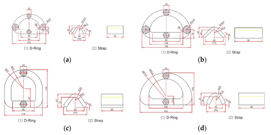
Figure 1.
Four types of D-Rings (unit: mm). (a) Type 1 D-Ring with 3.0 tonf MBL; (b) Type 2 D-Ring with 20.0 tonf MBL; (c) Type 3 D-Ring with 20.4 tonf MBL; (d) Type 4 D-Ring with 25 tonf MBL.
2.2. Material Modelling of the D-Ring Devices
As shown in Table 2, the materials for the rings and straps are mild steel (JIS standard SS41) or high-tensile steel (JIS standard S45C, SF540B). For a conservative assessment, we assumed the mild steel material to have an initial yield strength of 235 MPa. A Lüders plateau of 0.5% prior to plastic hardening was considered. The material constants of the power-law hardening rule, the plastic hardening exponent () and the strength coefficient () were assumed to be 0.15 and 800 MPa, respectively. The flow stress of the material is shown in Figure 2, which will be applied to the numerical simulations to represent the behavior of the D-rings and straps. The flow stress and plastic strain curves were implemented in ABAQUS/implicit in a data table form. The numerical analysis used the temperature-independent von Mises plasticity model.
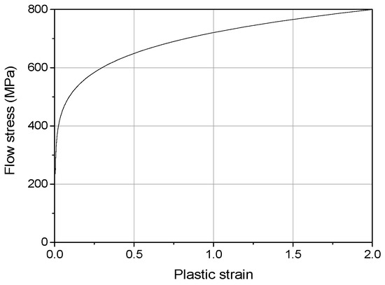
Figure 2.
Flow stress of the D-ring and strap material.
2.3. Finite Element Analysis Modelling
The commercial FEM program ABAQUS/Implicit was used to investigate the structural strength of the lashing devices. Figure 3 shows the three-dimensional finite element modelling of type 1–4 lashing devices. The devices were modeled with hexahedral solid elements with eight nodes and reduced integration (C3D8R). The D-ring consists of the strap and ring. As the strap is welded to the deck structures, fixed boundary conditions were adopted to the adjacent joints. The loads were applied using enforced displacement at the mid-surface with a kinematic coupling, as shown in Figure 4. A static friction coefficient of 0.7 was assigned for the contact between the straps and rings [13].
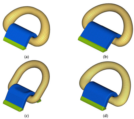
Figure 3.
FEM models for the four types of D-Rings. (a) Type 1 (3.0 tonf MBL); (b) Type 2 (20.0 tonf MBL); (c) Type 3 (20.4 tonf MBL); (d) Type 4 (25 tonf MBL).
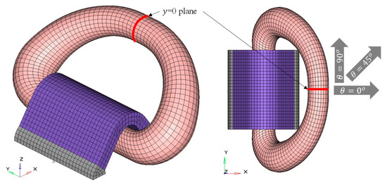
Figure 4.
Mid-plane of the D-rings and in-plane angle .
To clarify the load acting on the rings, the load angle, which is divided into two parts: in-plane angle θ and out-of-plane angle ϕ, as shown in Figure 5, should be defined. IMO CSS acknowledges that effective lashing conditions include ϕ of more than 45°; thus, the minimum ϕ was assumed to be 45°, whereas the maximum ϕ was 60°. Meanwhile, θ values of 0°, 45°, and 90° were considered (Figure 4). As a result, a total of 24 load cases were implemented in the numerical analysis of the rings.
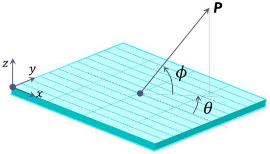
Figure 5.
Definition of the cargo lashing in-plane angle and out-of-plane angle .
We investigated the structural strength of the lashing devices with respect to their ultimate strength. The element length was approximately 3 mm, as the predicted deformation of the structures based on the load cases was reasonably predicted with the element length.
2.4. Ultimate Strength Assessment of the D-Rings
As shown in Figure 6, the numerical results showed that the resultant force as a function of the displacement monotonically increased without the obvious onset of plastic hardening. Therefore, the tangent intersection method was implemented to determine the ultimate strength. This was proposed by Save [14], where the tangent of the elastic and plastic parts of the loading-deformation curve was drawn, and the tangent point corresponding to the loading value was defined as the limit load. First, the slopes in the elastic and plastic hardening regions were identified. The contact point between their tangent lines was considered as the ultimate strength.

Figure 6.
Tangent intersection method for determining the ultimate strength. The red dot indicates the ultimate strength.
The tangent line in the elastic region can be drawn as follows:
- Find the starting load point, at which the displacement until the initial contact is excluded;
- Select a sufficiently large load as the termination load;
- Fit the curve between the starting and termination loads;
- Repeat step 3 until the coefficient of determination of the curve is greater than 99%.
Similarly, the tangent line in the plastic hardening region was drawn, as follows:
- Find the starting load corresponding to the maximum displacement of 50 mm;
- Select a sufficiently small load as the termination load;
- Fit the curve between the starting and termination loads;
- Repeat step 3 until the coefficient of determination of the curve is greater than 98%.
A coefficient of determination of over 98% was used because a coefficient greater than 99% was difficult to achieve for nonlinear curves.
3. Numerical Analysis—Deck Structures
3.1. Shinan Ferry No. 5
As a reference vessel for the structural strength assessment, Shinan Ferry No. 5, which was launched in September 2014, was chosen as the target vessel. This vessel can transport 160 passengers and 15 vehicles (12 passenger cars and 3 trucks). The principal dimensions of Shinan Ferry No. 5 are listed in Table 3. Figure 7 shows the photograph of the vessel. The vessel has a deck of 12 mm steel plate, and a longitudinal girder and transverse web frame with 250 × 7 + 75 × 9 mm T-bar. The distance between the longitudinal girders and transverse web frame was 1500–2000 mm. The longitudinal stiffeners are 130 × 130 × 12 mm angle bars (L-bar) with a spacing of 1500 mm.
Table 3.
Principal dimensions of Shinan Ferry No.5.
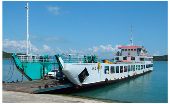
Figure 7.
Photograph of the target vessel Shinan Ferry No. 5 (http://sanews.co.kr/2817, accessed on 1 May 2022).
3.2. Ultimate Strength Assessment of the Deck Structures
In this study, the structural analysis was carried out with the FE of the deck plate of Shinan Ferry No. 5. Table 4 and Figure 8 show the scantling and FE model of the deck structure, respectively. The deck structure was modelled using a quadrilateral finite-membrane-strain shell element with reduced integration (S4R). The flow stress shown in Figure 2 was applied to the computational analyses. We assumed the expected locations where the D-ring were set up. Figure 9 shows the D-ring locations with their appropriate labels (L1 to L6). The load was applied to the D-rings at each location under different cases, comprising five in-plane angles (−90°, −45, 0, 45, and 90) and two out-of-plane angles (45 and 60°. Thus, a total of 60 load cases were used.
Table 4.
Scantlings of the deck structure.
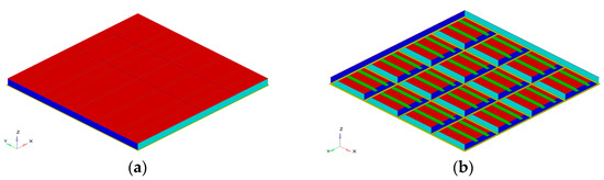
Figure 8.
FE model of the deck structure of Shinan Ferry No. 5. (a) Isometric view—Top surface; (b) Isometric view—Bottom surface.
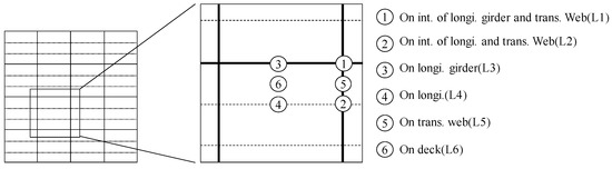
Figure 9.
Assumed locations of the D-Rings.
Numerical analyses with different mesh densities were performed to investigate mesh size sensitivity. The selected mesh densities have element lengths of 5, 10, 20, and 50 mm. A load of 1 kN was applied in the normal direction to the elements at L1–L6. The deflection according to the mesh densities was analyzed.
3.3. Ultimate Strength Assessment of the Deck Structures Considering the Thickness Reduction and Corrosion of the Deck Plate
The thickness of the deck plate on Shinan Ferry No. 5 is 12 mm. However, other ferry vessels may have different thicknesses and dimensions of their structural members. Thus, we assumed a minimum thickness of 6 mm for the deck structures to obtain a conservative estimate and analyzed the variation of the ultimate strength with this thickness. The Ministry of Oceans and Fisheries of South Korea provides the enforcement regulations for the Ship Safety Act, including the guidance for the corrosion allowance (Table 5). The scantlings of the deck structural members with the corrosion allowances are presented in Table 6.
Table 5.
A Guidance for corrosion allowances (https://www.law.go.kr/법령/선박안전법시행규칙 accessed on 1 May 2022).
Table 6.
Scantlings of the deck structural members considering corrosion wastage.
4. Results and Discussion
The ultimate strength and elongation obtained from the nonlinear finite element analysis (FEA) are listed in Table 7, where the load cases are defined as Dx-ϕyy-θzz: x is the type number, yy is the out-of-plane angle, and zz is the in-plane angle. The ultimate strength of the type 4 D-ring cannot satisfy the CS for the different load cases. As expected, the type 1 D-ring exhibited the lowest ultimate strength. Even with their highly similar shape, i.e., upper radius of 19 mm and similar width, the ultimate strength of the type 4 D-ring was lower than that of the type 2 D-ring. This can be ascribed to the larger height of the type 4 D-ring, and different strap shapes. For the type 4 D-ring to comply with the lashing criterion of IMO CSS, materials with better mechanical properties should be considered for the ring and strap, and the ring diameter should be increased. The ultimate strength and elongation of the D-rings vary notably with the load angles. This may be attributed to the dependence of the ultimate strength and elongation on the shape of the rings and straps, and contact area between these components. This aspect was difficult to quantify, but they do certainly influence the ultimate strength of the D-rings.
Table 7.
Nonlinear FEA results for D-rings.
The convergence results are shown in Figure 10. For L6, the deflection increased with the decrease of the element length, and it converged when the element length was less than 10 mm. Therefore, the deck structure should comprise element lengths of less than 10 mm.
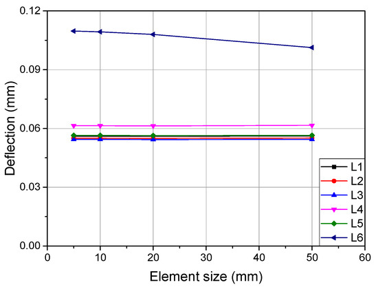
Figure 10.
Convergence study for the mesh size sensitivity at different D-ring locations.
The tangent intersection method was used to identify the ultimate strength of the deck structure. The numerical results are listed in Table 8. The label has Lx-ϕyy-θzz where x is the type number, yy is the out-of-plane angle, and zz is the in-plane angle. The minimum ultimate strength of 29.82 tonf of the deck structure was obtained at L6 with ϕ of 60° and θ of 0°, which was considerably larger than the MBL of the lashing device.
Table 8.
Nonlinear FEA results for the deck structure.
Considering the thickness of the deck structure, the ultimate strength of the deck structure was less than the CS of the D-rings for L5 and L6. The lowest ultimate strength was obtained for L6-ϕ60-θ00, where only a type 1 D-ring can be applied (see Table 9).
Table 9.
Nonlinear FEA results for hull deck structures with reduced deck thickness of 6 mm.
With a deck thickness of 6 mm, the deck structure should be supported by adding a local stiffener and carling, as shown in Figure 11. Thus, we investigated the variations of the ultimate strength of the deck plate using a carling for the L6-ϕ60-θ00 load case, where the lowest ultimate strength was predicted. The carling has a height of 130 mm and a thickness of 6–24 mm. Figure 12 presents the ultimate strength as a function of the carling thickness. From the results, a D-ring of 25 tonf MBL should be used with a carling thickness of more than 12 mm.
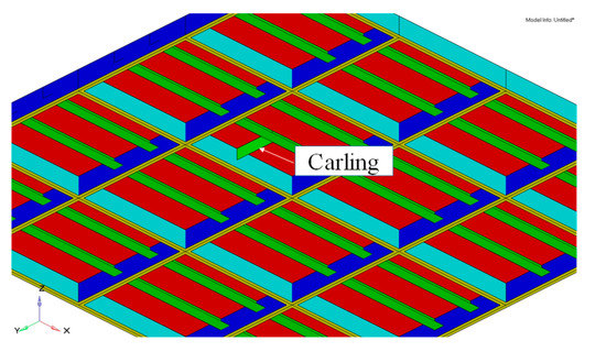
Figure 11.
Local reinforcement with the carling.
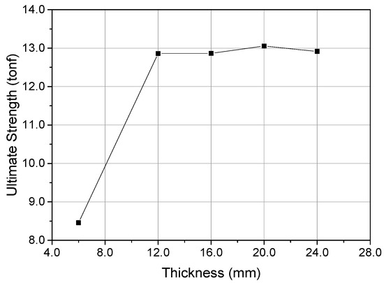
Figure 12.
Ultimate strength of the deck structure as a function of the carling thickness.
The ultimate strength of the deck structure considering the corrosion wastage of case L6-ϕ60-θ00 was predicted numerically, as shown in Figure 13. The numerical analysis revealed a sufficient ultimate strength of 13.58 tonf, compared to the CS of D-rings.
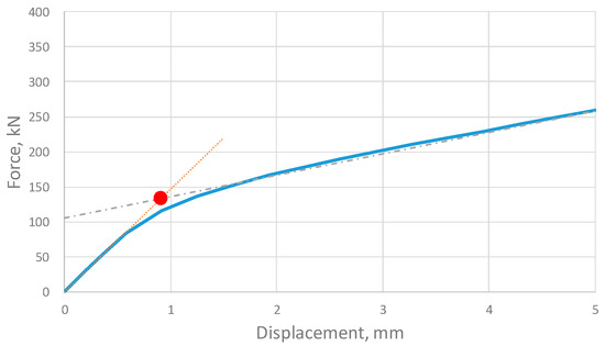
Figure 13.
Ultimate strength for L6-ϕ60-θ00 considering the corrosion wastage.
5. Conclusions
In this study, a series of FEA were carried out using the commercial program ABAQUS/Implicit to predict the ultimate strength of D-rings and deck structures. From the numerical simulation of the D-rings, their force–displacement relationship was determined. The FEA results were compared with the lashing criterion of IMO CSS. The IMO CSS provides the conservative minimum strength of the D-rings in most cases. In addition, the ultimate strength of the deck plates to which the D-rings were clamped were also numerically analyzed. The ultimate strength of the deck structures subjected to various load cases was predicted, whereby sufficient strength values greater than those of the D-rings were obtained. The influence of the decrease in thickness and corrosion wastage on the ultimate strength was also analyzed. To comply with IMO CSS, the deck plate with a thickness of 6 mm should have a local stiffener. Meanwhile, the effect of the corrosion wastage on the deck strength can be neglected.
The numerical analysis and its outcomes improved the understanding of the safe lashing of cargoes. This can afford more precise prediction of the ultimate strength, particularly of the D-rings and deck structures, thereby achieving the target safety levels for the crews and carrying ships. Nevertheless, the need for further experimental study to validate the feasibility of the numerical analysis is acknowledged. In future work, the numerical and experimental analyses of the lashing devices should also consider exposure to a series of temperatures, boundary conditions, and loading rates. These projects will require several material and numerical tests under such conditions, which will be very challenging.
Author Contributions
Conceptualization, W.N. and K.K.; formal analysis, K.K.; investigation, S.-J.P., and K.K.; methodology, K.K.; software, S.-J.P.; validation, K.K.; visualization, W.N. and K.K.; writing original draft, S.-J.P.; writing—review and editing, W.N. All authors have read and agreed to the published version of the manuscript.
Funding
This work was supported by a grant from Tongmyong University Innovated University Research Park(I-URP) funded by Busan Metropolitan City, Republic of Korea (IURP2201).
Institutional Review Board Statement
Not applicable.
Informed Consent Statement
Not applicable.
Conflicts of Interest
The authors declare no conflict of interest.
References
- European Maritme Safety Agency (EMSA). Annual overview of marine casualties and incidents. 2021. [Google Scholar]
- Allianz Global Corporate & Specialty (AGCS). Safety and shipping review. 2022. [Google Scholar]
- Turnbull, S.R.; Dawson, D. The securing of rigid semi-trailers on roll-on/roll-off ships. Int. J. Mech. Sci. 1997, 39, 1–14. [Google Scholar] [CrossRef]
- Turnbull, S.R.; Dawson, D. The dynamic behaviour of #exible semi-trailers on board Ro}Ro ship. Int. J. Mech. Sci. 1999, 41, 1447–1460. [Google Scholar]
- Kirkayak, L.; Suzuki, K. Numerical analysis of container stacks dynamics. Proc. PAAMES AMEC 2008, 3, 205–208. [Google Scholar]
- Kirkayak, L.; De Souza, V.A.; Suzuki, K.; Ando, H.; Sueoka, H. On the vibrational characteristics of a two-tier scaled container stack. J. Mar. Sci. Technol. 2011, 16, 354–365. [Google Scholar] [CrossRef]
- Li, C.; Wang, D.; Cai, Z. Experimental and Numerical Investigation of Lashing Bridge and Container Stack Dynamics Using a Scaled Model Test. Mar. Struct. 2021, 75, 102846. [Google Scholar] [CrossRef]
- Yulianto, T.; Sujiatanti, S.H.; Ariesta, R.C.; Aufar, M.R. Strength Analysis of a Container Lashing on the Container Ship by Using Finite Element Method. In Proceedings of the 6th International Seminar on Ocean and Coastal Engineering, Environmental and Natural Disaster Management, Surabaya, Indonesia, 6–7 November 2018; pp. 101–105. [Google Scholar]
- Ghesmi, M.; Brindley, S. A Nonlinear Finite Element Method to Assess Loads on Container Stacks. Ocean Eng. 2021, 235, 109430. [Google Scholar] [CrossRef]
- Shin, S.-H.; Hwang, G.-H. Development of the container securing program for large container carriers. J. Soc. Nav. Archit. Korea 2014, 51, 362–368. [Google Scholar] [CrossRef][Green Version]
- Germanischer Lloyd (GL). Rules for classification and construction. 2013. [Google Scholar]
- International Maritime Organization (IMO). Code of safe practice for cargo stowage and securing. 2011. [Google Scholar]
- Sullivan, J.F. Technical Physics, 99th ed.; Wiley: Hoboken, NJ, USA, 1988; p. 204. [Google Scholar]
- Save, M. Experimental verification of plastic limit analysis of torispherical and toriconical heads. Press. Vessel. Pip. Des. Anal. 1972, 1, 382–416. [Google Scholar]
Publisher’s Note: MDPI stays neutral with regard to jurisdictional claims in published maps and institutional affiliations. |
© 2022 by the authors. Licensee MDPI, Basel, Switzerland. This article is an open access article distributed under the terms and conditions of the Creative Commons Attribution (CC BY) license (https://creativecommons.org/licenses/by/4.0/).