Abstract
In this study, the problem of surface waves induced by water flow in a flow channel was investigated. The mathematical model based on the potential wave theory was established, and a new analytic solution to the corresponding initial and boundary value problem was proposed. To confirm our analytic solution, the mathematical model was applied to simulate experiments conducted in a flow channel in the laboratory. Using our analytic solution, water surface elevations and flow velocities at certain locations in the channel were compared with experimental results. Comparisons between our analytic solution and experimental results confirmed our theory that amplitudes and propagating phases are in very close agreement. Our analytic solution can be used to calculate variations in pressure and velocity along the water depth, which are expensive to calibrate and obtain in experiments. Although our analytic solution was established based on linear theory, it is very practical for applications studying the basic properties of surface elevation, velocity, and pressure of the flow field induced by water current both in space and time.
1. Introduction
Physical modelling of surface tidal bores may be dated back to the late 19th century. Darcy and Bazin [1], Favre [2], and Benet and Cunge [3] conducted classical experiments with a focus on free surface characteristics, including the evolution of surface bores and positive surges. Tricker [4] provided an elementary introduction and good concept of the tidal bore, in which properties of bores, propagation characteristics, and the associated undulation features were identified. Modern experimental studies focused more on the turbulent characteristics using velocity-measuring instruments with high temporal resolution: e.g., digital particle imaging velocimetry and an acoustic Doppler velocimeter. The physical studies in tidal bores commonly highlighted the rapid increase in water depth associated with a sharp deceleration in longitudinal velocity as the bore propagated [5,6,7,8,9]. A key feature of surface bore propagation is the production of large-scale turbulent structures beneath the bore [10]. Measurements using particle imaging velocimetry yielded a relationship between the mean vorticity downstream of a bore and the bore Froude number [10]. The experimental findings also demonstrated a strong shear layer formed at the toe of the wave [6]. Chanson and Docherty [8] proposed an ensemble-averaged technique over a variable-interval time-average technique or a traditional time-average technique to better quantify this highly unsteady process. Particle tracking under breaking and undular bores documented intensive transient sheet flow motions of sliding and rolling particles beneath the roller of breaking bores [9].
Using theoretical analysis for problems of unsteady surface waves, Stoker [11] gave a general solution that could be a good guideline for research in this topic. Peregrine [12] used a finite difference method to calculate and investigate the time-dependent behavior of undular bores. Sozer and Greeberg [13] investigated the time-dependent free surface flow generated by a submerged line source or sink. The submerged line source or sink was used to produce the unsteady nonlinear potential flow. Wei and Kirby [14] considered long-wave properties and used the extended Boussinesq equation for nonlinear wave propagation. EI et al. [15] considered undular bores as the Boussinesq type and used the Whitham modulation theory for a one-phase periodic travelling wave to obtain an asymptotic analytical description of an undular bore in the Su–Gardner system for a full range of depth ratios across the bore. Landrini and Tyvand [16] studied the inviscid free surface flow due to an impulsive bottom flux on constant depth by investigating analytically and numerically. Marchant [17] found two types of analytical undular bore solutions to the initial boundary value problem for the modified Korteweg–de Vries equation. White and Helfrich [18] used the Dubreil-Jacotin–Long theory for solitary waves to study the internal hydraulic jump, considering energy dissipation. Bestehorn and Tyvand [19] studied interactions between two undular bores in a long rectangular channel by solving the two-dimensional Laplace equation with fully nonlinear free surface conditions. A finite difference method applying the nonlinear coordinate transformation was used to solve the problem. Ali and Kalisch [20] investigated the energy loss of a dispersive undular bore model. The conclusion was that there was no energy loss in the dispersive model. Berry [21] presented an approximate theory describing the rigidly travelling profile of undular bores. The theory combined the standard of hydraulic jump with concept of Hamiltonian operators and zero-energy eigenfunctions. The undular bores appeared to be travelling up rivers driven by high tides, consisting of a smooth wave front followed by a series of undulations. Vargas-Magaña et al. [22] used the full water wave equations and bidirectional Whitham–Boussinesq equations to simulate the characteristics of undular bores. They found that the Whitham–Boussinesq systems gave solutions in excellent agreement with the numerical solutions of the full water wave equations for the positions of the leading and trailing edges of the bore up until the onset on modulational instability. The Whitham–Boussinesq systems could be used to accurately model surface water wave undular bores. Grimshaw and Kamchatnov [23] presented an analytic model for a weakly dissipative shallow-water undular bore. Hatland and Kalisch [24] and Grimshaw and Kamchatnov [25] studied the wave-breaking phenomena occurring in undular bores generated by a moving weir and in an integrable shallow water system. El et al. [26] investigated undular bore transition in bi-directional conservative wave dynamics. Overall, due to the intrinsic nonlinear behavior of undular bores, numerical methods were inevitably used to solve the problem.
For analytic solutions to unsteady water wave problems, Lee et al. [27] proposed a transient wavemaker theory in which the time-dependent function was resolved using the Laplace transform, the x-coordinate function was expressed using the Fourier Cosine function, and the z-coordinate function was obtained by a direct integration method. The time-dependent analytic solution could be obtained without a problem, but the involved inversed Laplace transform was complicated and could be impossible for some mathematical functions. Joo et al. [28] proposed an analytic solution to the initial and boundary value problem of the wave generation problem. The unique part of the solution was to utilize a particular solution to satisfy the time-dependent boundary condition, and then other dependent functions were solved following the concept of separation of variables. Using a similar approach, Chang et al. [29] solved the piston-type wavemaker problem, and Lin et al. [30] solved the wavemaker problem for irregular waves. Note that applying this approach to similar problems needs to obtain a particular solution for the boundary condition that was inconvenient.
In this study, a new time-domain analytic solution to the problem of flow-induced undular bores in a laboratory channel is presented. The method was motivated by combining the applicability approach of Lee et al. [27] and Joo et al. [28]. Our analytic solution was applied to simulate undular bore generation carried out in the experiments. Comparisons of surface elevation and horizontal and vertical velocities between our solution and the experiments are intended to show the capability of this analytic solution. Finally, variations of flow velocity and pressure along with the water depth were investigated.
2. Problem Descriptions and Analytic Solutions
The problem of surface waves induced by a current was sketched as shown in Figure 1, where a channel with a length and a constant water depth was chosen. A full-depth inflow velocity was specified on the left side, and the other end of the channel was a vertical wall. It was expected that, with the inflow current, the variation and increase of water surface would be generated and propagated toward the end of the channel.
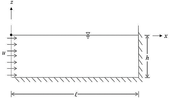
Figure 1.
Definition sketch of an inflow channel.
A linear potential wave theory was used to describe the water motion. The flow velocity was defined as
where was the gradient operator and was the potential function. The boundary-value problem was described as [31].
The governing equation was the Laplace equation:
As for the boundary conditions, the combined kinematic and dynamic boundary condition at the free surface and the bottom boundary condition were written, respectively, as
where as the inflow condition was
in which was the inflow velocity. The end vertical wall condition was
Initially, the water in the channel was still, and there was no surface disturbance on the free surface. Equations (2)–(6) represent the initial and boundary value problem from Figure 1. Next, an analytic solution to the problem will be presented, and descriptions for each solution step will be shown.
The potential function of the flow field was a function of spatial coordinates and time . The first step was to process the function, and Equations (2)–(6) were manipulated using the Fourier cosine transform. The function was expressed in terms of the finite Fourier cosine series, and the flow potential function was expressed as [32].
where , , and were defined as
The solution step then moved to solve the function of and . The boundary value problem from Equations (2)–(4), including the governing equation, the free surface, and bottom conditions, was rewritten, following the Fourier cosine transform of Equation (9), as
Equation (10) thus obtained was a nonhomogeneous second-order differential equation, and the solution was written as [32].
in which was the homogeneous solution and was the particular solution. The solution to Equation (13) was obtained by using the method of variation of parameters.
where the coefficients and shown in Equation (14) were determined by substitutions of Equations (14) and (15) back into Equation (13) and then utilizing the free surface and bottom boundary conditions, Equations (11) and 12).
When substituting Equations (13)–(15) into the free surface and bottom boundary conditions, we obtained
Equations (16) and (17) show a relation of the coefficients and and a second-order differential equation in time, which was solved to obtain
where and were the integration constants, which should then be determined by using the initial conditions.
For initially still water in the problem domain and no free surface disturbances, we used the zero potential function and zero surface elevation to obtain
Similar to obtaining , we also obtained
Thus, the initial boundary value problem was solved. The flow potential function was explicitly expressed as
Note that in the present linear theory, the potential function is linearly proportional to the inflow velocity.
Once the potential function was completely determined, the free surface elevation could then be calculated using the Bernoulli equation
The horizontal and vertical fluid velocities and were also expressed, using the definition of Equation (1), as
In using our analytic solution, one can expect the end vertical wall of the water flume could reflect oncoming waves. Therefore, if the calculated results containing no reflected waves are required, the length of the water flume could be specified long enough to ensure that the reflected waves had not come back into the flow domain yet and to obtain pure surface waves generated by the inflow specified at the left boundary.
3. Simulation of Experimental Results
Our analytic solution was applied to simulate undular bores generated in the laboratory. The detailed information of the experiments, including laboratory deployment and experimental data analysis, were described in [7]. The schematic diagram of the experimental setup is shown in Figure 2a, and bore generations in the theory are shown in Figure 2b.
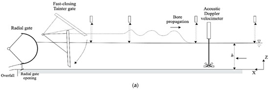
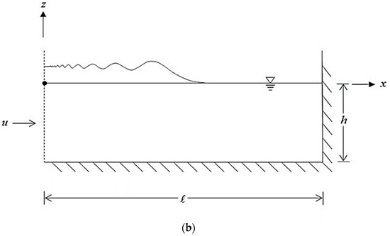
Figure 2.
Schematic diagrams of surface bore generation (a) in the experiment and (b) in theory.
In the experiment, the water flume was 12 m long, 0.5 m wide, and made of glass sidewalls with a smooth PVC bed. The flow entered the channel from the right side (refer to Figure 2a). The surface bores were generated by rapidly closing the Tainter gate located on the left side, and the generated undular bores propagated toward the right side. The water surface was recorded by an acoustic displacement meter at five locations, and at the same locations, flow velocities were measured using an acoustic Doppler velocimeter at different water depths. The recorded data of water surface and flow velocity were synchronized in time. The flow conditions used in the theory, as shown in Figure 2b, were the water depth (h = 0.199 m) and the flow velocity (0.189 m/s), specified on the left boundary.
To generate undular bores in the experiment, a steady flow was induced in the entire channel, and the flow entered from the right side and exited on the left. The gate located on the left side near the end was then closed quickly to block the flow, and undular bores were generated, propagating to the right (refer to Figure 2a). In the theory, however, the flow entered the channel from the left side, and undular bores were generated. Note that the experiments were conducted in [7], and the coordinate system as shown in Figure 2a was used for data acquisition and data analysis. However, in the mathematical model, a traditional Cartesian coordinate system, with the x-axis pointed to the right and z-axis pointed upward, was adopted. Therefore, the generated data both from the experiments and the analytic solution for a specific location along the wave flume should be carefully identified for mutual comparisons. Furthermore, the characteristics of undular bores generated in the wave flume [7] were fully investigated and can be utilized to ensure good comparisons for analytic solutions.
The comparison of surface elevation between experimental data and the theory at a location 4 m in front of the gate in the experiment is shown in Figure 3. The abscissa indicates dimensionless time of wave propagation, which was copied from [7]. Since the exact time of bores generated in the experiment was not recorded, the theoretical surface waves were shifted to align the first peak to compare the entire wave form. Figure 3 indicates that for the first peak, the theoretical result was 0.175, whereas the experimental result was 0.195. The theoretical result was 10.3% lower than the experimental result for the first peak of the surface elevation. For the propagating time, since the first peak was aligned, the second peak for the theory was 57, whereas the experiment was 55. The theoretical time for the second peak passing the observatory location was 3.64% slower than the experimental result. In general, overall amplitudes and repeated time were comparable; however, as can be expected, the flow condition in the experiment was turbulent, and the surface waves propagated faster than those in the analytic solution.
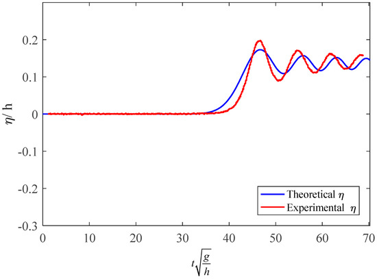
Figure 3.
Comparison of surface elevation at a location 4 m in front of the gate.
The next comparisons were the horizontal and vertical velocities of the flow. The same set of data from the surface elevation in Figure 3 was used. The measured location in water was near the free surface, which was z = 0.145 m above the bottom in the experiment and was z = −0.054 m in the theory. The time series of the flow velocities and from the experiment and analytic solution are plotted in Figure 4, where the surface elevation is also indicated for reference. For the horizontal and vertical velocities, both the experimental results and analytic solutions were consistent with variations of the free surface elevations. The experimental surface waves moved faster than the analytical results, along with the horizontal velocity. Overall, the comparisons were generally satisfactory, including amplitudes and phases. Note that in the experiment, the flow conditions were turbulent and irregular; therefore, irregular variations shown in experimental data are obvious.
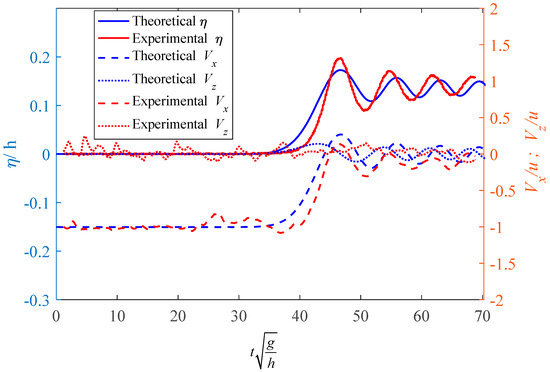
Figure 4.
Comparisons of surface elevation, horizontal velocity, and vertical velocity.
Additionally, the methods of surface bore generation were different in the experiment and in the mathematical model, as indicated in Figure 2. The experimental data has been adjusted according to a coordinate transformation and an analog of inflow direction, generating the undular bores. The horizontal velocity’s direction was reversed by adding a negative sign, and the inflow velocity was then subtracted to have the same inflow situation as the theory.
4. Spatial and Temporal Evolution of Undular Bores
Our analytic solution was applied to examine some characteristics of undular bores, including variations of the velocity and pressure along the water depth and along the water flume. Using the inflow velocity of 0.2 m/sec, water depth of 0.5 m, and length of the channel 12 m, the surface elevation and flow velocities along the channel at 20 s are plotted in Figure 5. The velocities were calculated at the depth z = −0.1 m. The horizontal velocity was in phase with the surface elevation, whereas the vertical velocity was in a phase of a quarter of the wavelength ahead. Note that near x = 0, fluctuation resulted in horizontal velocity. Since in our analytic solution the x function of the potential function was expressed in the Fourier cosine series, the x derivation to obtain the horizontal velocity calculated at x = 0 was certainly zero. The outlook of the expression indicated not satisfying the boundary condition, Equation (5); however, the mathematical expression inherited an asymptotic satisfaction similar to the step function expressed in terms of Fourier cosine functions. A closer look of Figure 5 for 0 < < 0.05 is shown in Figure 6. The horizontal velocity indeed approached the boundary condition . In short, the present analytic solution can describe time evolution of surface bores along the water channel.
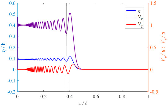
Figure 5.
Surface elevation and flow velocities along the channel (inflow velocity 0.2 m/s and water depth 0.5 m).
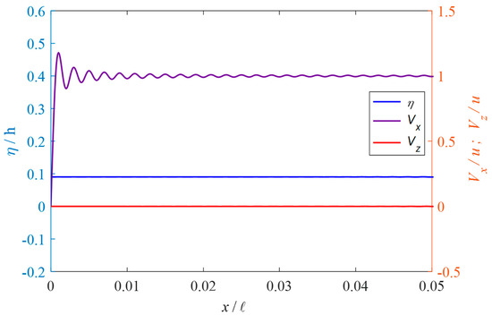
Figure 6.
Closer look of horizontal velocity near x = 0.
The variations of horizontal and vertical velocities at different water depth are shown in Figure 7, and the surface elevation is also included for reference. The conditions considered were m, m/s, and the location m. The water depths z/h = 0, −0.2, −0.5, and −0.9 are calculated. Both the horizontal and vertical velocities decreased as the water depth increased and reached closer to the bed, and near the bottom the vertical velocity was very small. The dynamic pressure expression using our analytic solution can be expressed as
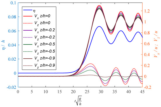
Figure 7.
Variation of horizontal and vertical velocities at different depths.
The variations of pressure at different water depths are shown in Figure 8. The pressure was nondimensionalized by the water pressure . and are fluid density, and is the gravity constant. The pressure was in phase with the free surface elevation, and the magnitude decreased with the increase of the water depth.
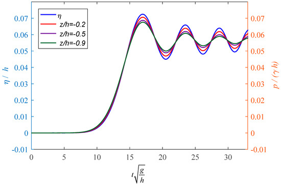
Figure 8.
Variation of pressure at different water depths.
5. Conclusions
A mathematical model for undular bores induced by water flow in a laboratory flume was established, and a new time-domain analytic solution was presented for the initial and boundary value problem. Our methodology was developed from modifying the solutions for generations of surface waves, in which the linear potential wave theory was used. In our analytic solution, the Fourier cosine transform and solutions to the nonhomogeneous second-order differential equations were used to solve for the space functions, whereas the free surface boundary condition was solved for the time-dependent function. Our solutions compared reasonably well with the experimental data in surface elevations, horizontal velocities, and vertical velocities. Our analytic solution can be used to describe evolutions of the surface elevation, the velocities, and pressure distributions along the water depth and along the channel, which are expensive to obtain in experiments. This analytic model can be used to simulate variations of undular bores in space and time induced by water flow in the wave channel.
Author Contributions
Conceptualization, J.-F.L. and H.C.; methodology, J.-F.L., C.-T.C. and K.-T.L.; validation, C.-T.C. and K.-T.L.; investigation, C.-J.L.; writing—original draft preparation, J.-F.L. and H.C.; writing—review and editing, H.C., C.-J.L. and C.-T.C.; project administration, J.-F.L. and H.C.; funding acquisition, C.-T.C., C.-J.L. and J.-F.L. All authors have read and agreed to the published version of the manuscript.
Funding
This research was funded by Sanming University under grant number 22YG01, and by the Ministry of Science and Technology, Taiwan, grant number MOST 106-2221-E-006-109.
Institutional Review Board Statement
Not applicable.
Informed Consent Statement
Not applicable.
Data Availability Statement
Not applicable.
Acknowledgments
Financial support from Sanming University under Grant Number 22YG01 and the Ministry of Science and Technology, Taiwan, under Grant Number MOST 106-2221-E-006-109 are gratefully acknowledged.
Conflicts of Interest
The authors declare no conflict of interest.
References
- Darcy, H.P.G.; Bazin, H. Recherches Hydrauliques (Hydraulic Research) Parties 1ère et 2ème; Imprimerie Impériales: Paris, France, 1865. (In French) [Google Scholar]
- Favre, H. Etude Théorique et Expérimentale des Ondes de Translation dans les Canaux Découverts (Theoretical and Experimental Study of Travelling Surges in Open Channels); Dunod: Paris, France, 1935. (In French) [Google Scholar]
- Benet, F.; Cunge, J.A. Analysis of experiments on secondary undulations caused by surge waves in trapezoidal channels. J. Hydraul. Res. 1971, 9, 11–33. [Google Scholar] [CrossRef]
- Tricker, A.R. Bores, Breakers, Waves and Wakes; Mills & Bon Limited: London, UK, 1964. [Google Scholar] [CrossRef]
- Hornung, H.G.; Willert, C.; Turner, S. The flow field downstream of a hydraulic jump. J. Fluid Mech. 1995, 287, 299–316. [Google Scholar] [CrossRef]
- Koch, C.; Chanson, H. Turbulence measurements in positive surges and bores. J. Hydraul. Res. 2009, 47, 29–40. [Google Scholar] [CrossRef]
- Chanson, H. Unsteady turbulence in tidal bores: Effects of bed roughness. J. Waterw. Port Coast. Ocean Eng. ASCE 2010, 136, 247–256. [Google Scholar] [CrossRef]
- Chanson, H.; Docherty, N.J. Turbulent velocity measurements in open channel bores. Eur. J. Mech. B Fluids 2012, 32, 52–58. [Google Scholar] [CrossRef]
- Khezri, N.; Chanson, H. Turbulent velocity, sediment motion and particle trajectories under breaking tidal bores: Simultaneous physical measurements. Environ. Fluid Mech. 2015, 15, 633–650. [Google Scholar] [CrossRef]
- Leng, X.; Chanson, H. Integral turbulent scales in unsteady rapidly varied open channel flows. Exp. Therm. Fluid Sci. 2017, 81, 382–395. [Google Scholar] [CrossRef]
- Stoker, J.J. Water Waves; Interscience Publishers, Inc.: New York, NY, USA, 1957. [Google Scholar]
- Peregrine, D.H. Calculations of the development of an undular bore. J. Fluid Mech. 1996, 25, 321–330. [Google Scholar] [CrossRef]
- Sozer, E.M.; Greeberg, M.D. The time-dependent free surface flow induced by a submerged line source or sink. J. Fluid Mech. 1995, 284, 225–237. [Google Scholar] [CrossRef]
- Wei, G.; Kirby, J.T. Time-dependent numerical code for extended Boussinesq equations. J. Waterw. Port Coast. Ocean Eng. 1995, 121, 251–261. [Google Scholar] [CrossRef]
- EI, G.A.; Grimshaw, R.H.J.; Smith, N.F. Unsteady undular bores in fully nonlinear shallow-water theory. Phys. Fluids 2006, 18, 027104. [Google Scholar] [CrossRef]
- Landrini, M.; Tyvand, P.A. Generation of water waves and bores by impulsive bottom flux. J. Eng. Math. 2001, 39, 131–170. [Google Scholar] [CrossRef]
- Marchant, T.R. Undular bores and the initial-boundary value problem for the modified Korteweg-de Vries equation. Wave Motion 2008, 45, 540–555. [Google Scholar] [CrossRef]
- White, B.L.; Helfrich, K.R. A model for internal bores in continuous stratification. J. Fluid Mech. 2014, 761, 282–304. [Google Scholar] [CrossRef][Green Version]
- Bestehorn, M.; Tyvand, P.A. Merging and colliding bores. Phys. Fluids 2009, 21, 042107. [Google Scholar] [CrossRef]
- Ali, A.; Kalisch, H. A dispersive model for undular bores. Anal. Math. Phys. 2012, 2, 347–366. [Google Scholar] [CrossRef]
- Berry, M.V. Minimal analytical model for undular tidal bore profile- quantum and Hawking effect analogies. New J. Phys. 2018, 20, 053066. [Google Scholar] [CrossRef]
- Vargas-Magaña, R.M.; Marchant, T.R.; Smyth, N.F. Numerical and analytical study of undular bores governed by the full water wave equations and bidirectional Whitham–Boussinesq equations. Phys. Fluids 2021, 33, 067105. [Google Scholar] [CrossRef]
- El, G.A.; Grimshaw, R.H.J.; Kamchatnov, A.M. Analytic model for a weakly dissipative shallow-water undular bore. Chaos Interdiscip. J. Nonlinear Sci. 2005, 15, 037102. [Google Scholar] [CrossRef]
- Hatland, S.D.; Kalisch, H. Wave breaking in undular bores generated by a moving weir. Phys. Fluids 2019, 31, 033601. [Google Scholar] [CrossRef]
- El, G.A.; Grimshaw, R.H.J.; Kamchatnov, A.M. Wave Breaking and the Generation of Undular Bores in an Integrable Shallow Water System. Stud. Appl. Math. 2005, 114, 395–411. [Google Scholar] [CrossRef]
- El, G.A.; Khodorovskii, V.V.; Tyurina, A.V. Undular bore transition in bi-directional conservative wave dynamics. Phys. D Nonlinear Phenom. 2005, 206, 232–251. [Google Scholar] [CrossRef]
- Lee, J.-F.; Kuo, J.-R.; Lee, C.-P. The Transient Wavemaker Theory. J. Hydraul. Res. 1989, 27, 651–663. [Google Scholar] [CrossRef]
- Joo, S.W.; Schultz, W.W.; Messiter, A.F. An Analysis of the Initial-value Wavemaker Problem. J. Fluid Mech. 1990, 214, 161–183. [Google Scholar] [CrossRef]
- Chang, H.-K.; Lin, S.-C. An Analytical Linear Solution of Transient Waves Generated by a Piston-Type Wave-Maker in a Finite Flume. J. Coast. Ocean Eng. 2009, 9, 25–41. [Google Scholar] [CrossRef]
- Lin, S.-C.; Chang, H.-K. An Analytical Wave-Maker Theory for Irregular Waves in a Finite Channel. J. Coast. Ocean Eng. 2009, 9, 225–238. [Google Scholar] [CrossRef]
- Dean, R.G.; Dalrymple, R.A. Water Wave Mechanics for Engineers and Scientists; World Scientific Publishing Co., Ltd.: Singapore, 1991. [Google Scholar] [CrossRef]
- Kreyszig, E. Advanced Engineering Mathematics; John Wiley & Sons Inc.: Hoboken, NJ, USA, 2011. [Google Scholar]
Publisher’s Note: MDPI stays neutral with regard to jurisdictional claims in published maps and institutional affiliations. |
© 2022 by the authors. Licensee MDPI, Basel, Switzerland. This article is an open access article distributed under the terms and conditions of the Creative Commons Attribution (CC BY) license (https://creativecommons.org/licenses/by/4.0/).