Abstract
The purpose of this study is to scrutinize the coupled hydroaeroelastic problem for a TLP design of a floating structure consisting of multiple vertical truncated cylinders which support a wind turbine (WT). The platform is exposed to the combined effects of water waves and wind loading. The motions of the platform are examined for seven different directions of the incident waves. The hydrodynamic problem was solved analytically by combining the physical idea of multiple scattering and the method of matched axisymmetric eigenfunction expansions in order to obtain analytical representations of the velocity potential around the cylindrical members of the platform, while the contribution of the WT is considered within the six degrees of motion of the floater. Numerical results are initially presented for the exciting forces acting on the platform, the added masses, and the hydrodynamic damping coefficients, as well as the RAOs of the platform’s motions. Furthermore, the shear forces and bending moments are calculated at the point where the WT is assembled with the floater. Finally, results for the total mooring forces are given.
1. Introduction
The worldwide continuously increasing needs for renewable energy have led to a thorough investigation of methods and structures exploiting solar, wind, and wave energy. In the field of offshore engineering, considerable efforts have been made to design floating structures supporting a WT. Since they have to be competitive against other existing methods of clean energy, the development and, accordingly, the evolution on this issue has led to a cost-effective solution for the exploitation of natural sources. However, taking into account the possible installation areas of offshore structures (UK, Denmark, Germany, Japan, and China), they must survive extreme environmental conditions very often, which is of critical importance for their survival and operability [,]. Offshore WTs can be either fixed on the seabed for shallow or intermediate depths as a monopile, or can be floating, attached to a mooring system, for larger water depths in the open ocean, where they can harvest higher wind and, consequently, wave power.
A general classification of the floating structure supporting a WT is as follows: spar-buoy type, pontoon-type, tension-leg platform (TLP), and semi-submersible. In the spar-buoy type, the floater, which is usually a cylindrical body made of steel, supports the tower of the WT and the rotor–nacelle assembly. Several studies have been conducted for this type [,,,,,,] of floating WT. Pontoon-type floaters are sometimes preferred due to their simplicity and the stability they offer to the structure. Fully coupled hydroaeroelastic analysis has been accomplished either in time or frequency domain including the influence of the WT, in the works [,,,,]. TLP platforms are widely used to support WTs which are permanently moored by means of tendons. This kind of mooring offers extremely small heave motions of the platform due to the high pretension of the tendons in the vertical direction. Among many studies of this subject are those of references [,,,,,,]. More complex configurations have been also investigated, encompassing oscillating water column (OWC) devices along with the WT. These structures can be very efficient, in a sense that they can exploit wind and wave energy at the same time. For this reason, they are widely called multipurpose floating structures. Representative research efforts on such an intriguing issue have been presented in [,,,,]. Finally, semi-submersible designs carrying three WTs in a special configuration have been investigated in [,,].
A fully coupled hydroaeroelastic analysis of the problem under consideration, as well as integrated tank testing of the corresponding model, is of great importance to secure reliability of the whole structure in the real environmental conditions. This can be achieved by a combination of analytical and numerical methods, along with experimental results, as clearly demonstrated, among others, in [,]. Analytical methods focus mainly on extracting closed-form solutions for the corresponding hydrodynamic boundary value problem by means of the velocity potential, while numerical methods treat the problem of the nonlinear analysis of the aerodynamic loading of the WT, which is explicitly considered as external loading to the floating structure and must be taken into account during the design stage. The aforementioned methods should be validated against experimental results. Tank testing of the corresponding model, based on similarity principle through Froude scaling law, allows, through measurements and observations, the correlation between the behavior of the model and the structure in real sea states, via sea spectral analysis.
The fully coupled hydroaeroelastic analysis of the structure is a very complicated procedure. In order to take into account the contribution of the WT to the total dynamic behavior of the floating structure, we made use of Hamiltonian dynamic analysis and blade element momentum theory. By this approach, we obtain estimations about the added mass, damping, and stiffness matrices which directly contribute to the inertial, gyroscopic, gravitational, and aerodynamic loading on the structure [,,]. In that direction, several CFD models have been also developed. These complicated numerical models deal with the unsteady aerodynamic characteristics of the flow around a rotating WT, which is supported by a floating platform subjected to surge, pitch, and yaw motions, due to the incoming waves [,,,]. The part of the hydrodynamic analysis of the problem was executed by the in-house developed code HAMVAB []. It is an efficient software which is based on analytical representations of the hydrodynamic parameters of the boundary value problem.
The purpose of this paper is to investigate the impact of a TLP mooring system on the dynamic behavior of a semi-submersible platform supporting a WT. Numerical results concerning the nondimensional response amplitude operators (RAOs) of the floater’s motions at the six degrees of freedom (DOF), the exciting wave forces, the added masses, and the hydrodynamic damping are presented. Furthermore, results are given for the shear forces at the point where the WT is assumed to be connected to the floating structure and the total forces at each branch of the mooring system. All the results are derived for several wave directions.
The paper is organized as follows: in Section 2, we describe in detail the geometry of the rectangular floating platform. Next, in Section 3, we proceed to the formulation and solution of the hydrodynamic problem, and we discuss thoroughly the effect that the WT has on the dynamics of the platform as a whole, while in Section 4, we present the TLP mooring system under consideration. Furthermore, in Section 5, the dynamic equation of motion of the floater is employed and numerical results for the exciting forces and moments acting on the structure, the added masses, and damping coefficients, along with the RAOs of the motions of the floater, are given. Section 6 discusses and presents results for the shear forces and bending moments calculated at the section where the WT is assumed to be integrated to the floating platform. Section 7 deals with the mooring tensions acting on each tendon of the TLP system, and finally the major conclusions are drawn in Section 8.
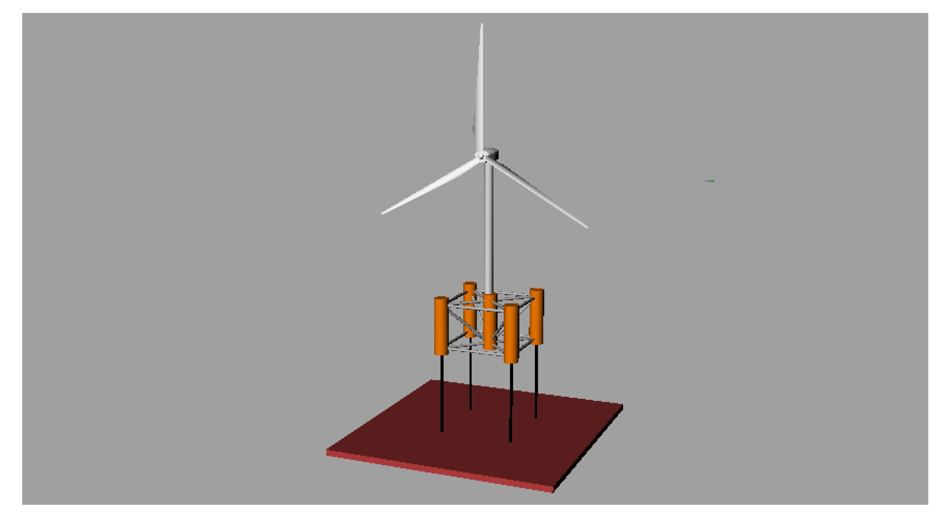
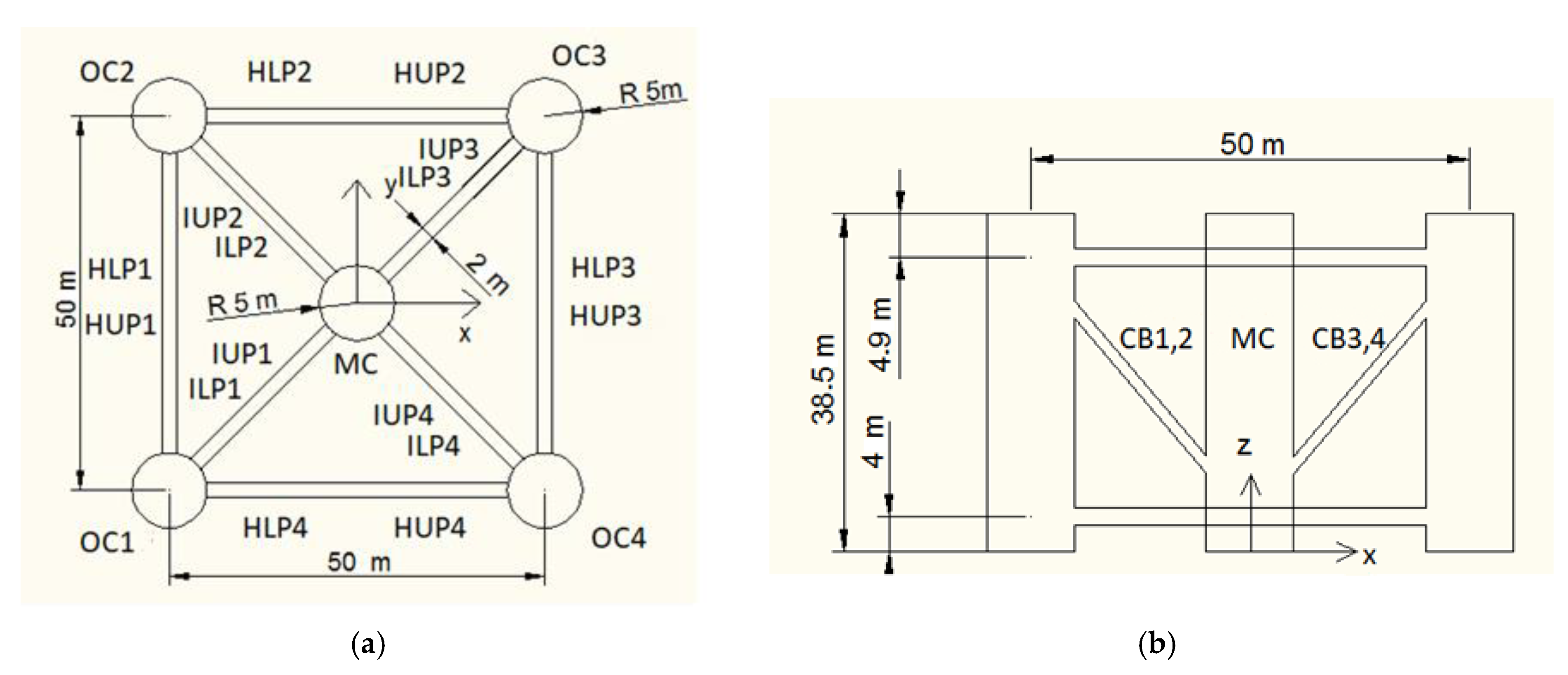
2. Description of the Floating Platform
The examined floating system is proposed to support a DTU WT. The draft of the platform is . The floating platform consists of four column-cylindrical tubes mounted at the corners of a rectangular floater, contributing the necessary buoyance, linked together with thinner, horizontal, and inclined tubular members, which provide stiffness to the floating structure. There are five sets of these smaller members. Particularly, two sets of four horizontal tubes each (upper and lower for a total of eight members) connect the offset buoy cylinders to each other at the top and the bottom of the structure. Two sets of four inclined tubes on the horizontal -plane (upper and lower for a total of eight members) connect the offset buoy columns to the main vertical column at the top and the bottom of the structure. Finally, four cross-cylindrical braces connect the bottom of the main column to the upper part of the offset columns. The tower of the WT is supported by a cylindrical member in the geometrical center of the rectangular deck of the floater and is cantilevered at above the still water level (SWL) to the top of the main column of the floating platform. The WT encompasses the tower, the blades, and the rotor–nacelle assembly. The whole structure is depicted in Figure 1 and Figure 2. Details about the dimensions of the main structural members of the floater are given in Table 1 and details about the secondary members are given in Table 2.
Figure 1.
The floating platform with the encompassed WT in 3D.
Figure 2.
(a) Plan view; (b) side view of the semi-submersible platform.
Table 1.
Floating platform geometry.
Table 2.
Member geometry.
For mooring purposes, each tendon of the TLP is attached to the center of the corresponding offset column. The mass of the platform, including the ballast, if needed, is . This mass was calculated as the sum of the weights: tower of the WT, the rotor–nacelle assembly, platform, and mooring system; plus, the applied pretension equals the buoyancy in the static equilibrium position in still water. From a mathematical perspective, for a TLP mooring system, this can be expressed as
where is the pretension of each tendon, is the sum of all the aforementioned weights, and denotes the buoyancy (which is equal to the weight of the displaced water). The CM of the platform, including the ballast, is located at below the SWL along the platform centerline. The roll and pitch inertias, which correspond to the rotation about the -axis and -axis, respectively, are , while the yaw inertia is . The properties of the floating platform are summarized in Table 3.
Table 3.
Floating platform structural properties.
3. Formulation of the Hydrodynamic Problem and the Role of the WT
The solution of the hydrodynamic boundary value problem is provided within the framework of analytical approaches. The Cartesian coordinate system is located at the SWL and in the geometrical center of the rectangular floater, with the vertical -axis showing positive upwards. The fluid is assumed inviscid, irrotational, and incompressible, so that the flow around the structure can be described by the linear potential theory. This assumption will be used to evaluate the coefficients for the added mass and hydrodynamic damping, as well as for the exciting forces. The velocity potential around each cylindrical member accounts for the hydrodynamic interactions among the members of the multicylinder arrangement using the physical idea of multiple scattering. According to this approach, various orders of propagating and evanescent wave modes, scattered by all the cylinders, are superimposed, leading to a series representation for the potential. This theory has been proved to be valid for any random multibody configuration and is independent of the number of elements included. Since it has already been thoroughly described in [], no further elaboration is accordingly needed in the present. The method of matched axisymmetric eigenfunction expansions was used to derive the first-order single-body hydrodynamic characteristics. The series representation for the diffraction potential around an arbitrary body of the structure is given by
where
where is the water depth, is the radius of the cylinder, and and denote the order modified Bessel functions of the first and second kind, respectively. The first term in (3) corresponds to the contribution of the incident wave field to the total wave potential around the body. In the case of isolated body–wave interaction, it holds that
where is the angle of wave incidence, and are the distance and azimuthal angle of the body coordinate system with respect to an inertial frame, is the wave number, and is the Kronecker’s delta function. The unknown complex coefficients in (3) are calculated using the method of matched eigenfunction expansion. Moreover, the are orthogonal functions in and are defined by
The eigenvalues are the roots of the nonlinear equation
which has to be solved iteratively, while the notation is used for the imaginary root.
The contribution of the WT to the dynamic behavior of the floater is expressed via the inclusion of the matrices for the added mass, damping, and stiffness to the dynamic equation of motion of the floater. These coefficients, actually, superinduce the external loads due to the presence (gravity) and operation (inertial/gyroscopic effects, aerodynamic loading) of the WT. In order to derive these matrices, we consider the problem within the Hamiltonian approach, by using the Lagrange’s equations. The dynamic behavior of the system can be described by the second-order differential equation
where are the generalized coordinates which prescribe the position of a specific point, is the Lagrangian of the system which is defined as the difference between its kinetic and potential energy, and are the generalized loads associated with the real loads (forces or moments). It should be mentioned that by defining the Lagrangian of a system, one can derive its equation of motion. The WT is modeled as a collection of concentrated masses for the blades, the hub, the nacelle, and the tower. The aerodynamic loads on the WT blades are calculated in the context of the blade element momentum theory, which accounts for the angular momentum of the rotor. However, this issue has already been scrutinized and for a complete discussion on it, the reader can refer to the publications [,].
The total mass of the WT is . The total tower height is and its mass is . The hub mass is and the nacelle mass is (Figure 1). As far as the three blades are concerned, the total mass of them is () and its length, excluding the hub, is []. All these details are summarized in Table 4.
Table 4.
WT properties.
4. The Mooring System
The dynamic behavior of the platform is examined under a TLP mooring system. The base of the anchoring system is located at the sea bottom, at a depth of . For a TLP system, the mooring forces, , acting on the platform in the direction are given explicitly by
where the coefficients express the platform’s mooring line stiffness, given by a six by six matrix. Indicatively, the , , and are given, which are defined as
where is the pretension force, is the unstretched length of each tendon, is the elasticity modulus, and is the total cross-section area. The pretension of each tendon is . The TLP mooring system increases the vertical stiffness of the system while reduces the heave period. Consequently, it can be used to avoid the resonance between the structure’s heave period and the incident’s wave period. It is anticipated that the motions of the TLP platform will be horizontal due to the large pretension in the vertical -direction. Table 5 and Table 6 summarize the main properties of the examined mooring system and cite the coordinates of the attachment points of the tendons, respectively.
Table 5.
Mooring system properties.
Table 6.
Coordinates of the upper and lower attachment points of the tendons.
5. Coupled Motion Equations
For a moored floating platform, including the influence of the WT on the dynamic behavior of the system, the coupled equations of motion can be expressed by the following system of differential equations [] by using Newton’s second law,
where , are the six by six matrices of the WT’s added mass, damping, and stiffness, respectively. The coupling of the WT’s dynamic behavior to the response of the floater is ensured by including the WT’s added mass, damping, and stiffness matrices into the governing equations of motions of the floating system. The accounting of these matrices into the equation of motion of the floater reduces the contribution of the WT to an external loading to the floating structure, attributing to inertial-gyroscopic effects, gravity, and aerodynamic forces. , , are the six by six matrices of the added mass, damping, and stiffness of the floating platform, respectively. is the mass of the platform, are the stiffness coefficients of the mooring lines, and, finally, are the external hydrodynamic forces acting on the direction expressed by a six by one column matrix. The solution of the equations of motions is carried out in the frequency domain.
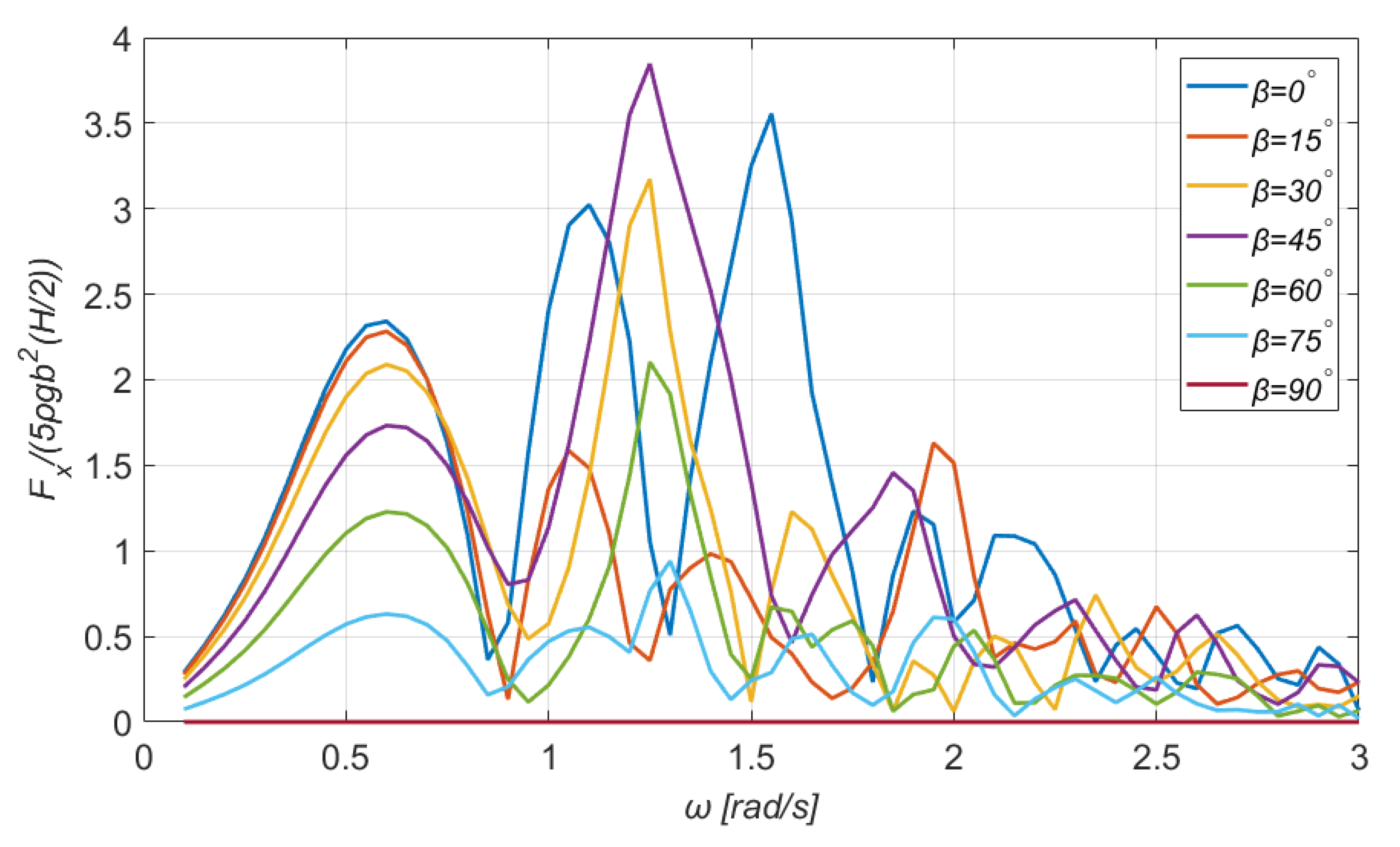
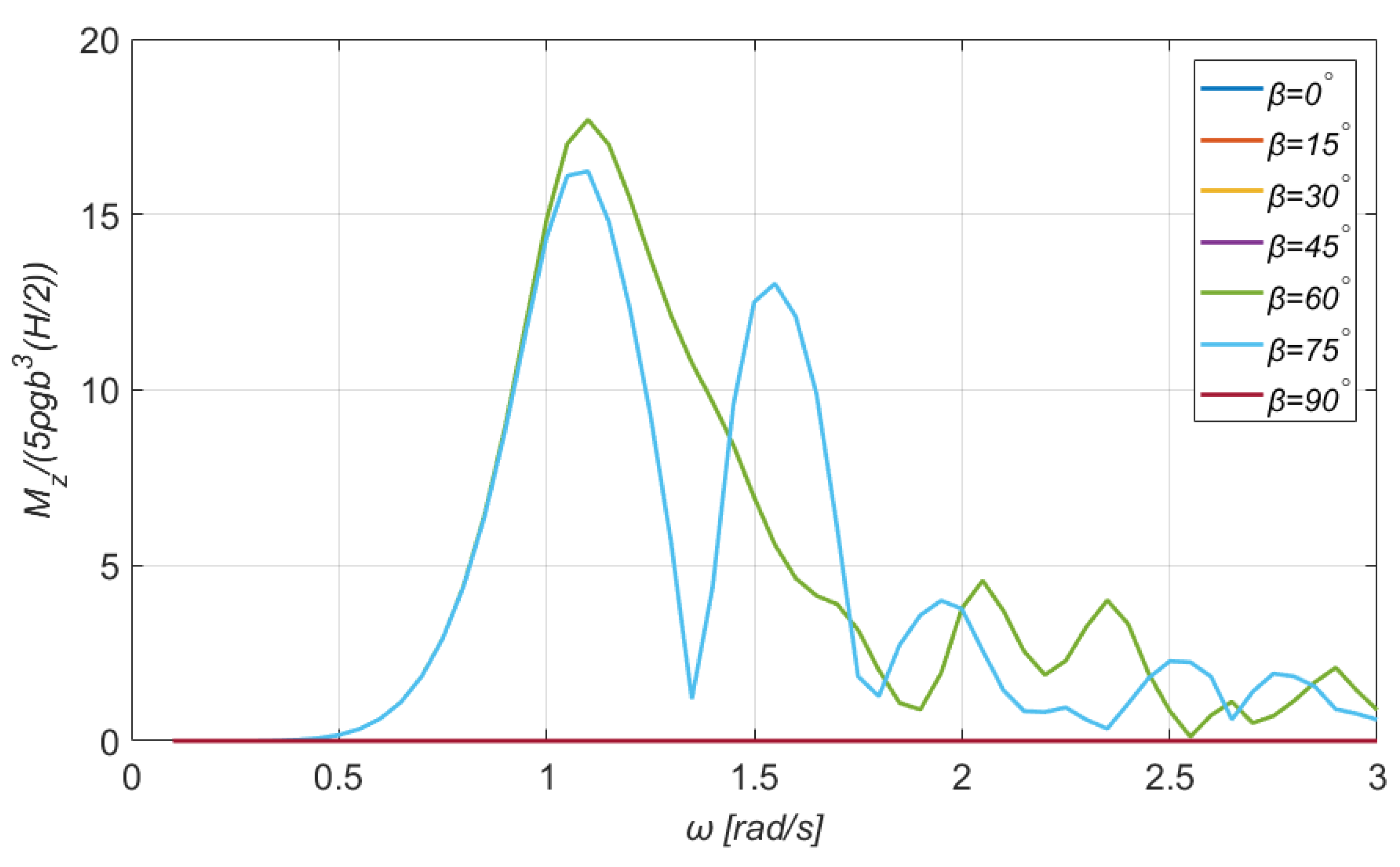
5.1. Exciting Forces and Moments
The exciting wave forces are derived by the integration of the hydrodynamic pressures over the wetted surface of the structure. The potential of the incident wave and the diffraction potential are those which contribute to the calculation of the hydrodynamic pressures, by exploiting the linearized Bernoulli equation. In the general form, they are given by Equation (12):
where is the normal vector pointing outwards from the wetted surface into the fluid, and holds for the wetted surface. Similarly, the overturning moments acting on the floating structure are given by
Figure 3, Figure 4, Figure 5 and Figure 6 demonstrate the normalized exciting forces and moments for a range of angular frequencies and for several directions of the incident wave. The exciting forces are nondimensionalized by the term , where the factor five holds for the number of bodies (NUBO), i.e., four offset columns and one main, is the water density, is the radius of the offset and main columns, and, finally, is the wave amplitude. In an analogous manner, the moments are normalized by the term . The exciting forces in the transverse direction and the moment are omitted owing to the double symmetry of the rectangular floater. It can be seen that for increasing wave frequencies, or equivalently smaller wavelengths, the exciting wave loads reduce.
Figure 3.
The horizontal exciting wave force on the TLP floating platform for a wide range of directions of the incident wave.
Figure 4.
The vertical exciting wave force on the TLP floating platform for a wide range of directions of the incident wave.
Figure 5.
The exciting overturning moment along the -axis on the TLP floating platform for a wide range of directions of the incident wave.
Figure 6.
The exciting wave moment around the -axis on the TLP floating platform for a wide range of directions of the incident wave.
Particularly, Figure 3 and Figure 4 show the normalized exciting forces along the -axes as a function of the incident wave’s angular frequency, for seven different angles of attack, ranging from . The maximum horizontal exciting force obtains the value 3.84, which occurs for a wave frequency of and for direction of the incident wave . Moreover, it is noticed that for waves propagating along the -axis, the loads in the direction are zero. On the other hand, the maximum vertical exciting force is 3.33 for wave frequency of (see Figure 4).
As depicted in Figure 5, the maximum exciting overturning moment along the -axis attains the value of 4.15 for the same pair of data with the corresponding exciting force, i.e., and . A feature that should be mentioned is the fact that when the wave direction is , the loads in the direction of the roll DOF (i.e., the overturning moment) are zero. Next, the exciting wave moment around the -axis, see Figure 6, demonstrates an interesting behavior. Particularly, when symmetry exists (for angles ), it is practically zero. It attains the maximum value of 17.30 for and . Furthermore, it is noticed that the curves for coincide also, and they form a pronounced secondary peak.
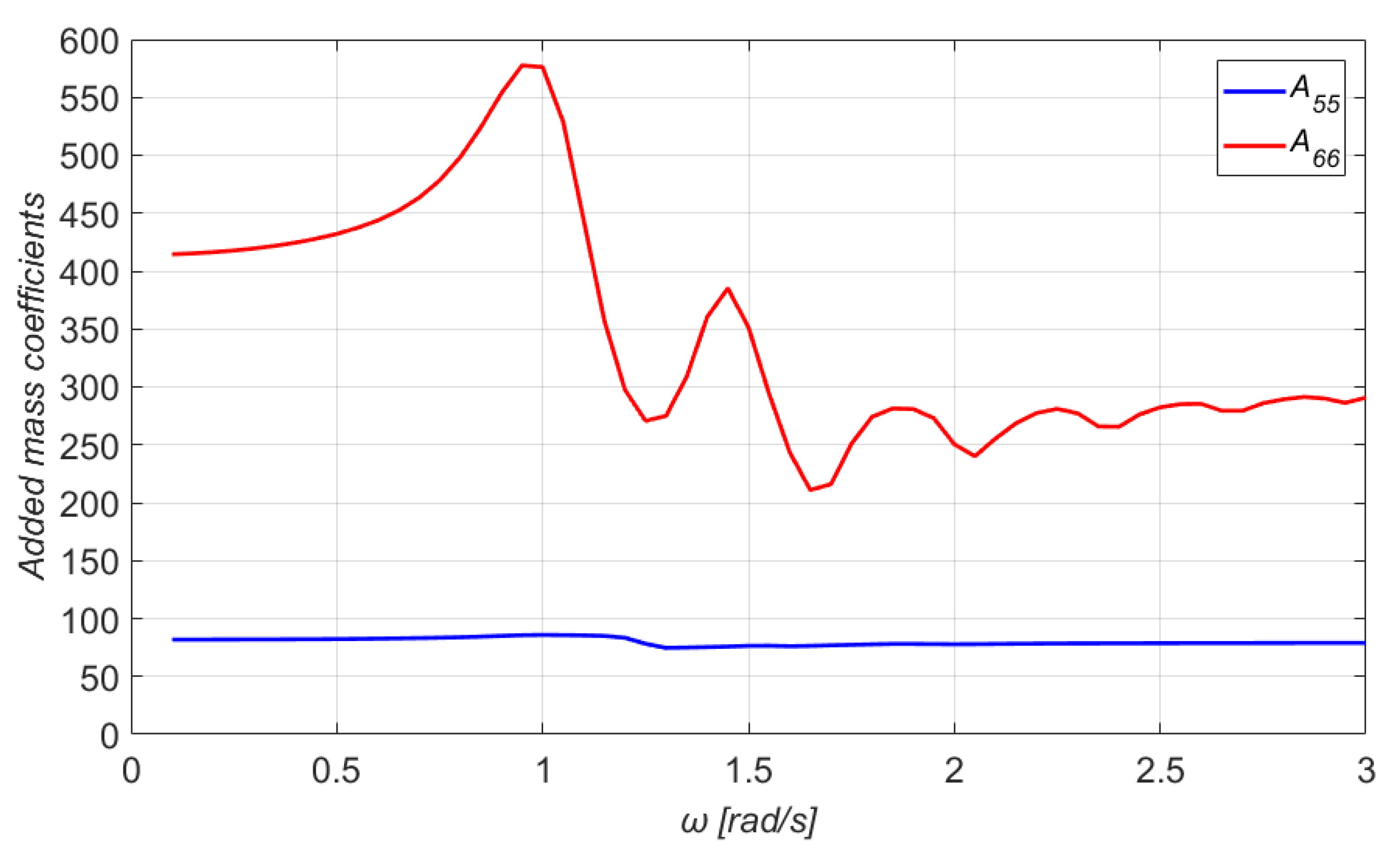
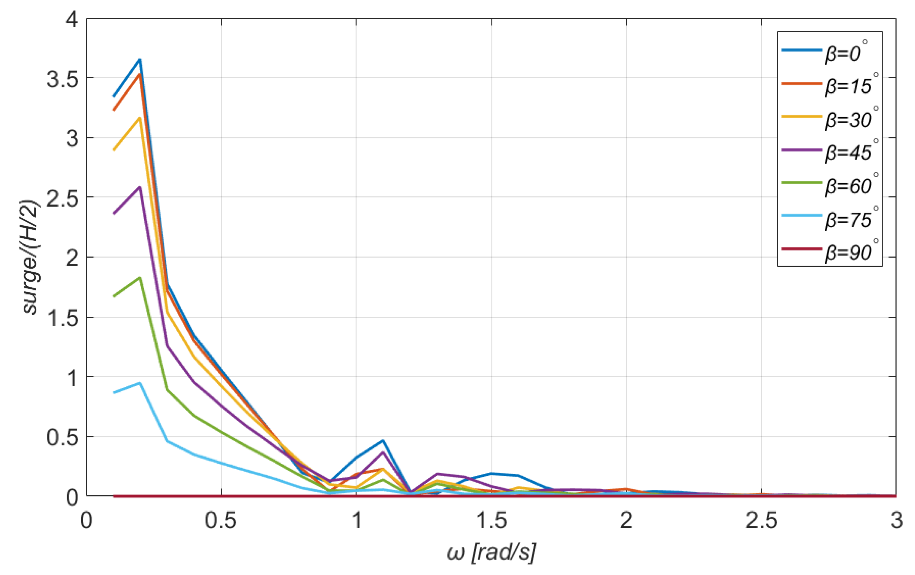
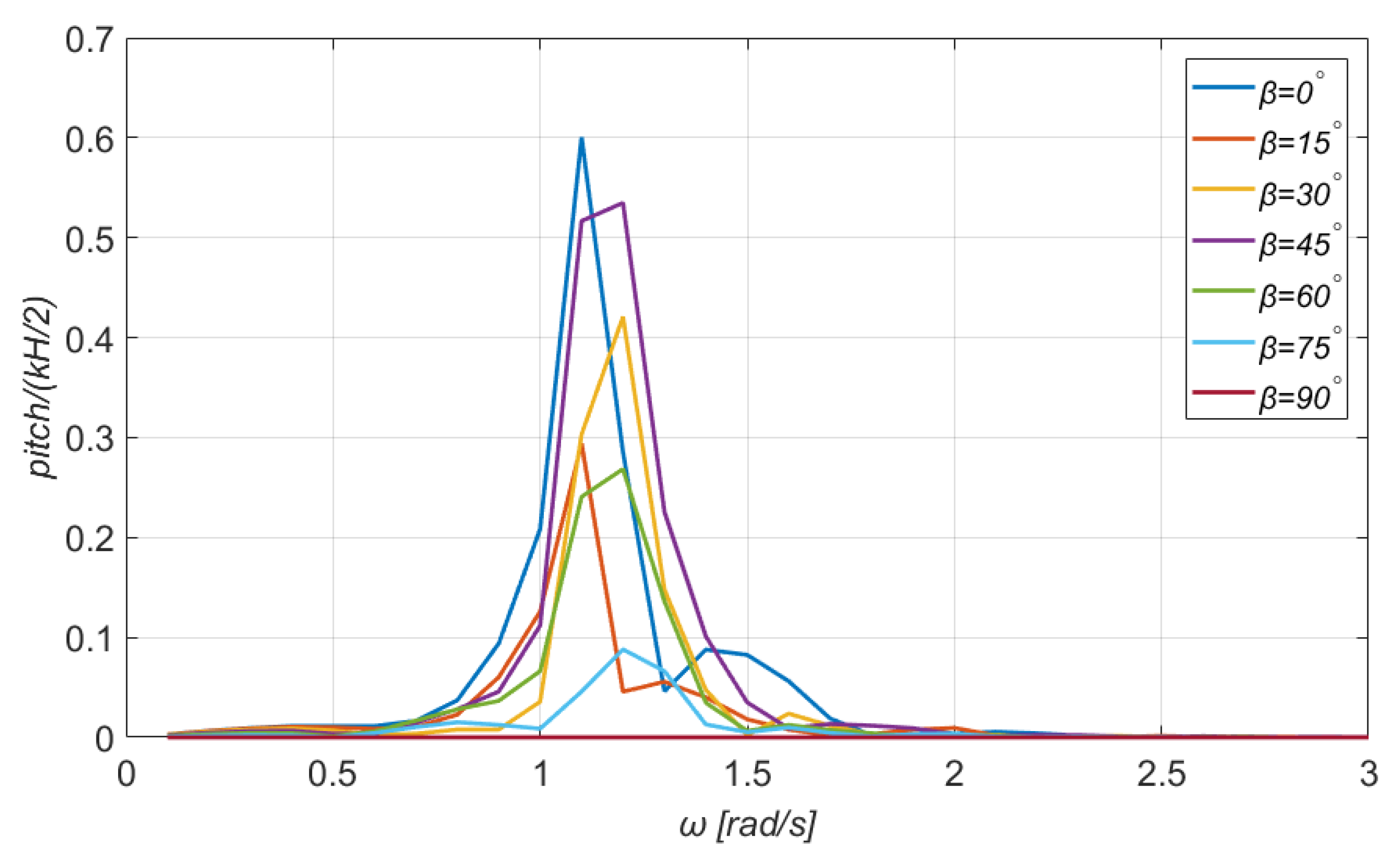
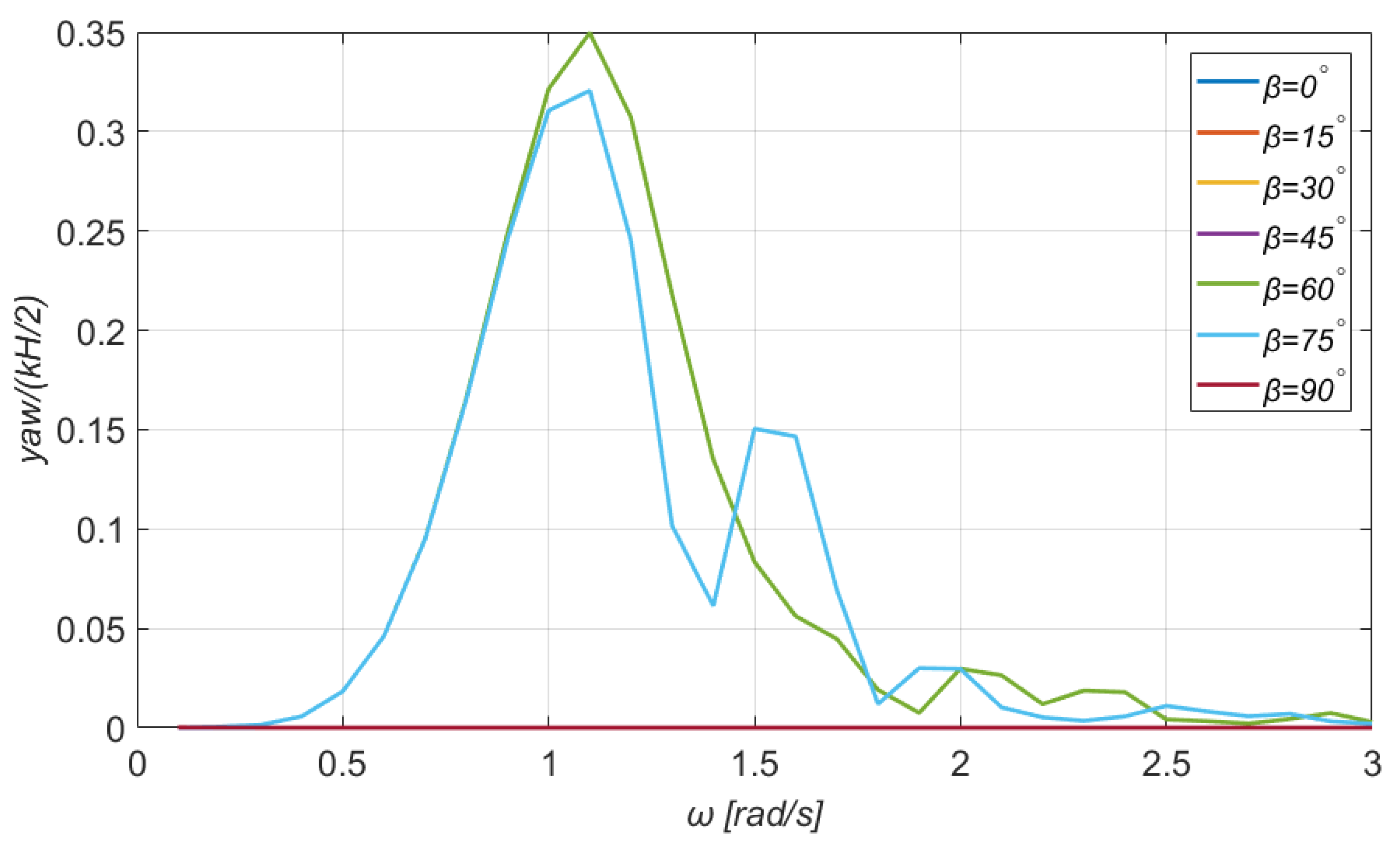
5.2. Added Masses, Hydrodynamic Damping, and Motions of the Floater
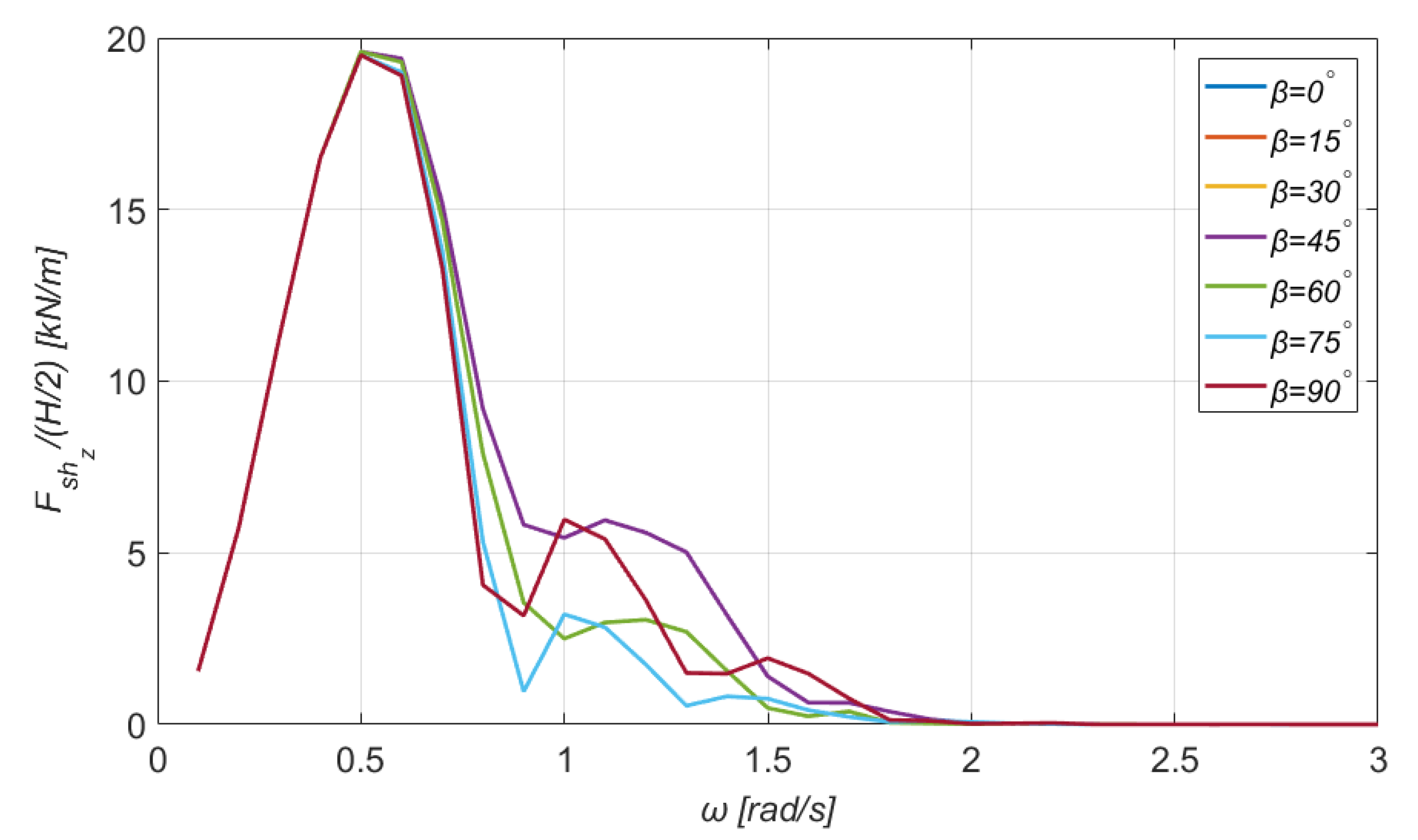
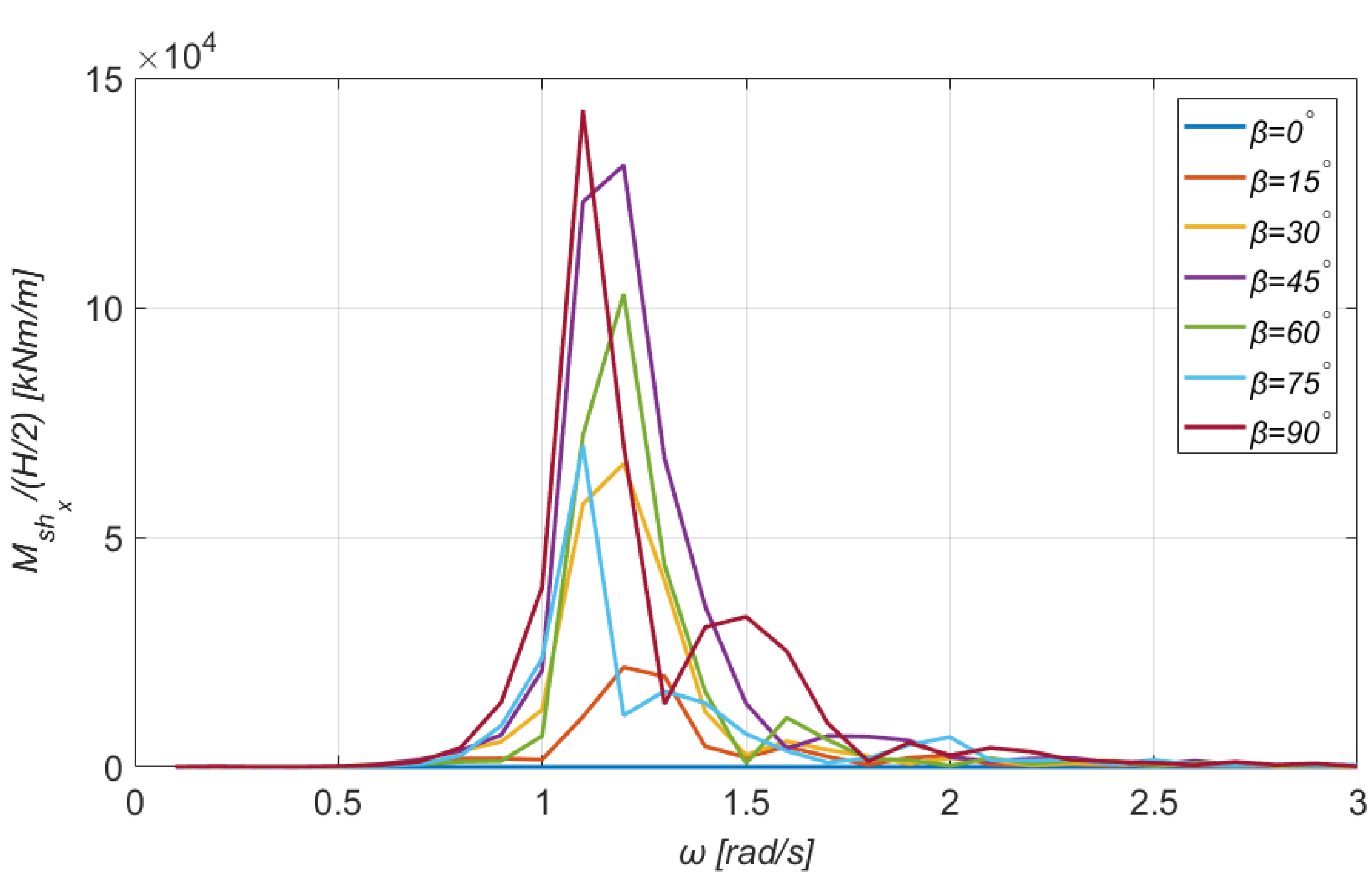
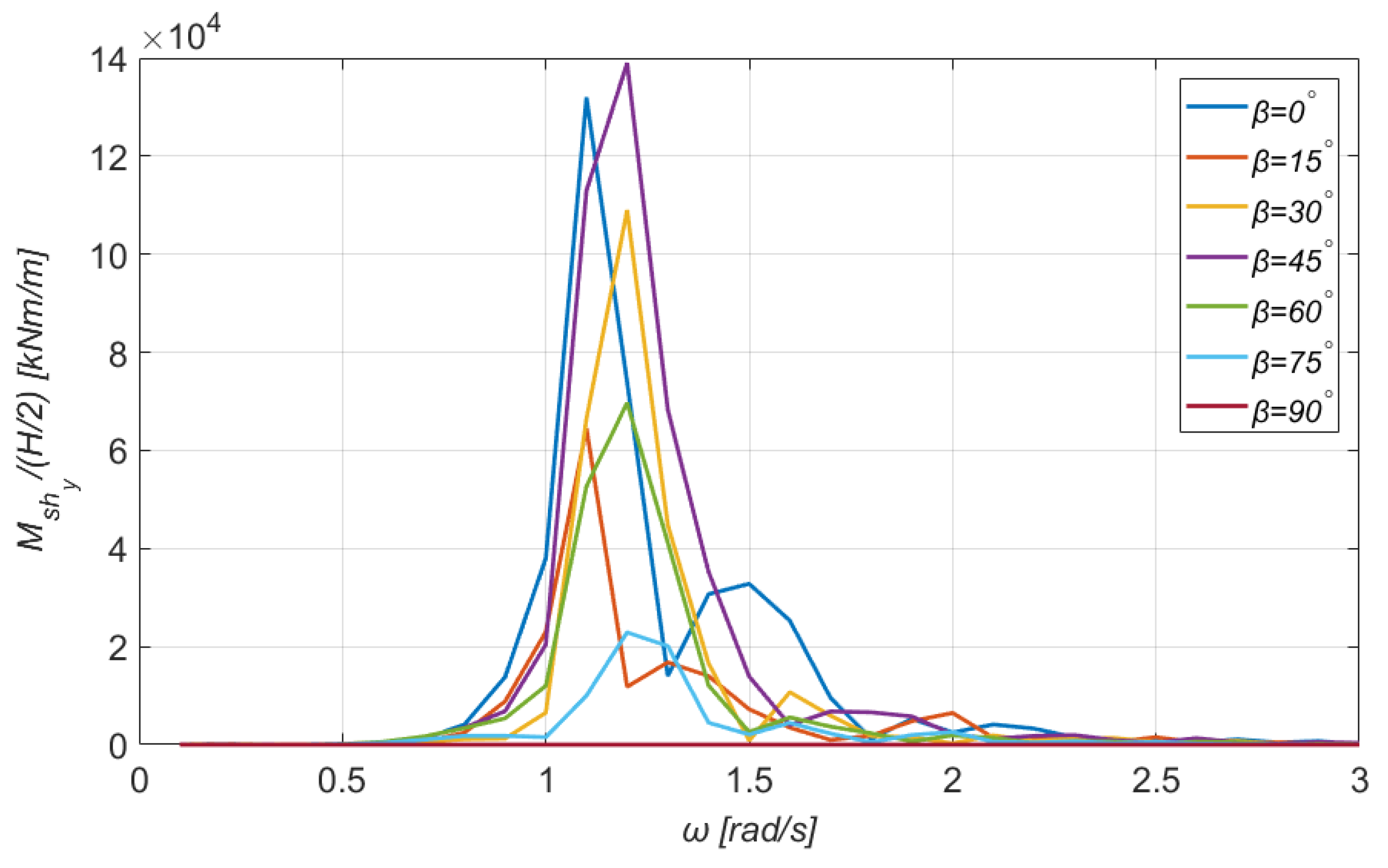
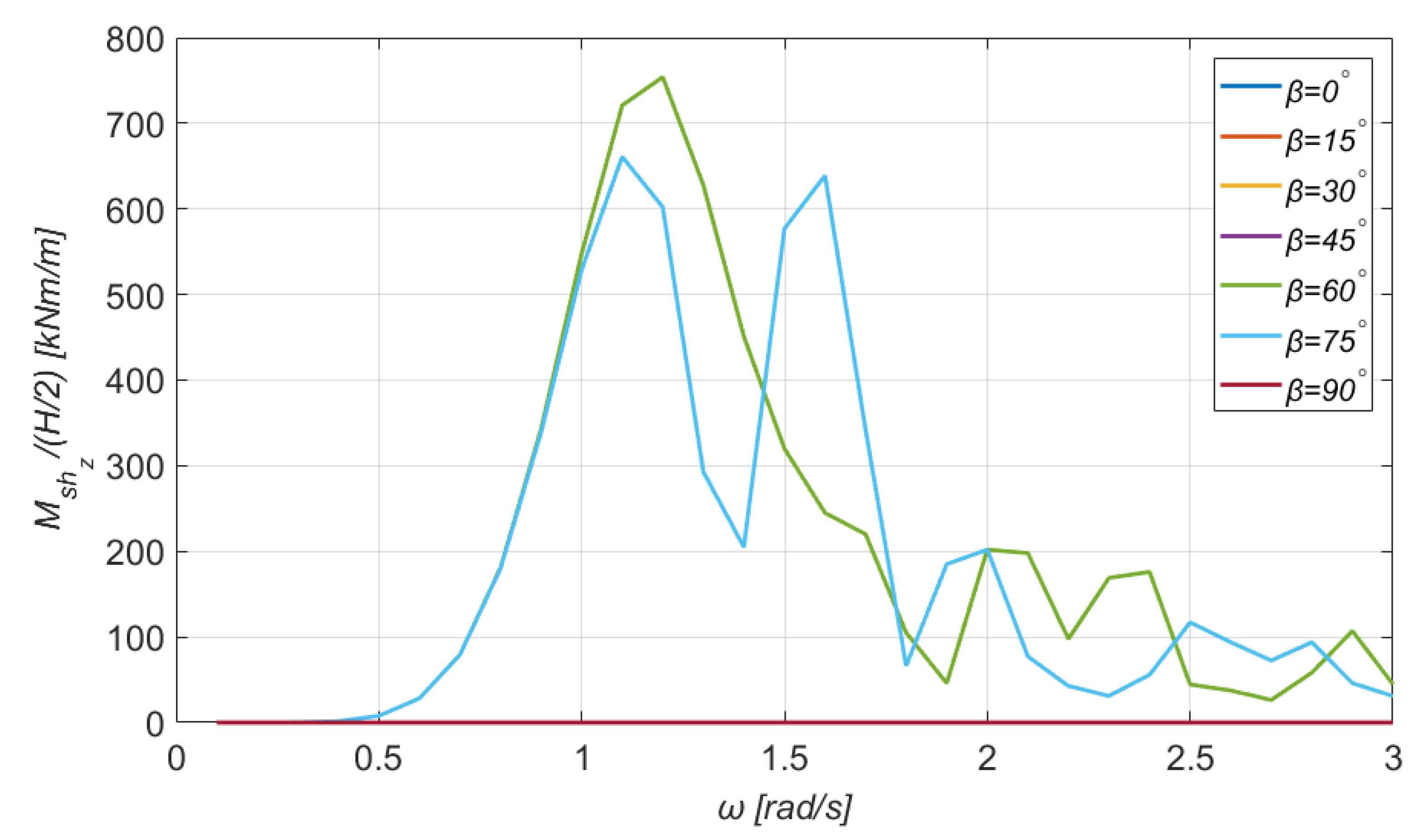
Figure 7 and Figure 8 demonstrate the behavior of added mass coefficients as a function of the incident wave frequency, while Figure 9 and Figure 10 show the behavior of several damping coefficients. Given that our analysis is performed in the frequency domain, the added masses and the damping coefficients are given explicitly by Equations (14) and (15), as follows:
and
respectively. The added mass and damping matrices are related to the solution of the radiation problem, which deals with the hydrodynamic loads on the platform owing to its forced oscillation in all six DOFs in otherwise calm water. All these coefficients are frequency-dependent and are listed below. The and added masses have been normalized by the term ,whereas the and by the term .
Figure 7.
The and added mass coefficients of the floater.
Figure 8.
The and added mass coefficients of the floater.
Figure 9.
The and damping coefficients of the floater.
Figure 10.
The and damping coefficients of the floater.
At this point, it should be mentioned that and coincide with and , due to the platform’s symmetry. This observation holds also for the elements , and , . Moreover, as it can be noticed from Figure 9 and Figure 10, the asymptotic values of the damping coefficients for zero and infinite wave frequencies tend to zero for all modes of motions, but the damping coefficient in heave for wave frequencies tending to zero attains a nonzero limiting value. The latter is related to the nonzero vertical exciting force in the low-frequency regime (see Figure 4) through the Newman–Haskind relation []
where is the excitation force and is the group velocity given by
It should also be mentioned that the damping coefficients form a main peak at intermediate frequencies. The and damping coefficients have been normalized by the term , whereas the and by the term .
Next, some numerical results for the RAOs of the motions of the floater are given. Similar to the comment of Section 5.1, the graphs for the sway and roll motions are omitted, owing to the double symmetry of the rectangular floater. The wind speed was taken as equal to . Figure 11, Figure 12, Figure 13 and Figure 14 show, graphically, the RAOs of the motions of the rectangular floater. As it is expected, the surge (and sway) motions are larger in the horizontal and transverse direction of the incoming wave, respectively. Consequently, their magnitude is reduced while the wave’s angle of attack deviates from these anticipated directions.
Figure 11.
Surge motion of the TLP combined floating platform and WT system for a wide range of directions of the incident wave. Wind speed: .
Figure 12.
Heave motion of the TLP combined floating platform and WT system for a wide range of directions of the incident wave. Wind speed: .
Figure 13.
Pitch motion of the TLP combined floating platform and WT system for a wide range of directions of the incident wave. Wind speed: .
Figure 14.
Yaw motion of the TLP combined floating platform and WT system for a wide range of directions of the incident wave. Wind speed: .
From Figure 12, the heave motion is proved to be rather independent of the wave direction and it also obtains much smaller values compared to surge and sway motions. This is a reasonable outcome, since a TLP mooring system sets significant constraints to the motion of the platform along the -axis. Finally, Figure 13 and Figure 14 depict the normalized rotational motions of the platform. The pitch motion is more intense when the incoming wave is parallel to the -axis and is zero when the direction of the incoming wave is . The maximum RAO of the pitch motion is 0.6 for . Regarding the yaw motion, it is zero for , , and . In addition, the curves for , and , are identical, while the maximum RAO of the yaw motion is identified in the latter case.
6. Shear Forces
In order to calculate the local displacement of the structure at a specific intersection point , we follow the analysis provided in the publication []. The local motion of each body can be calculated by the following equations:
where are the motions and rotations of the body relatively to the initial coordinate system (see Figure 2a), and denote the motions and rotations referring to the section point.
In order to calculate the shear forces, we consider the moored floating structure and the WT as a system of two bodies with kinematic coupling. The shear forces at the intersection point can be calculated by summing the forces acting on each body ( for the floating structure, and for the WT) (Figure 15). We examine the case where the section is at the point where the WT is assembled to the floating structure, i.e., above the SWL.
Figure 15.
The shear forces and bending moments are calculated at the point where the WT is incorporated in the floating system (section ).
In a similar manner, the bending moments are the sum of the external moments acting on each body and the moments generated by the previously mentioned forces, given by the cross product of the force and the distance from the section point, as follows in a vectoral form:
The shear forces and bending moments at the section of the column which supports the WT are shown graphically in Figure 16, Figure 17, Figure 18, Figure 19, Figure 20 and Figure 21. The maximum value of the horizontal shear force is 902 kNm/m for and , while the maximum transverse shear force is 941 kNm/m for and the same wave frequency. Furthermore, from Figure 18, it is noticed that the maximum vertical shear force is much smaller and seems to be slightly affected by the wave direction. In detail, the maximum value is 19.60 kNm/m at all cases, for .
Figure 16.
Horizontal shear force for the section (see Figure 15) for a wide range of directions of the incident wave.
Figure 17.
Transverse shear force for the section (see Figure 15) for a wide range of directions of the incident wave.
Figure 18.
Vertical shear force for the section (see Figure 15) for a wide range of directions of the incident wave.
Figure 19.
Horizontal bending moment for the section (see Figure 15) for a wide range of directions of the incident wave.
Figure 20.
Transverse bending moment for the section (see Figure 15) for a wide range of directions of the incident wave.
Figure 21.
Vertical bending moment for the section (see Figure 15) for a wide range of directions of the incident wave.
As far as the bending moments are concerned, the maximum value of the horizontal bending moment is 143,000 kNm/m and is obtained for and , and that of the transverse bending moment is 139,000 kNm/m, but it is obtained for the pair of parameters and . Finally, one can easily notice that the magnitude of the vertical bending moments is significantly smaller. Particularly, the curves for and coincide; the same observation holds for the curves corresponding to and . For orientations of the wave at , the vertical bending moment is practically zero. On this occasion, it should be pointed out that the units for the shear forces and the total tensions (in the following section) are kNm/m because the analysis is performed in the frequency domain and under the harmonic waves’ action. Consequently, these physical quantities are expressed in terms of the incident wave’s amplitude. The same comment holds for the bending moments as well.
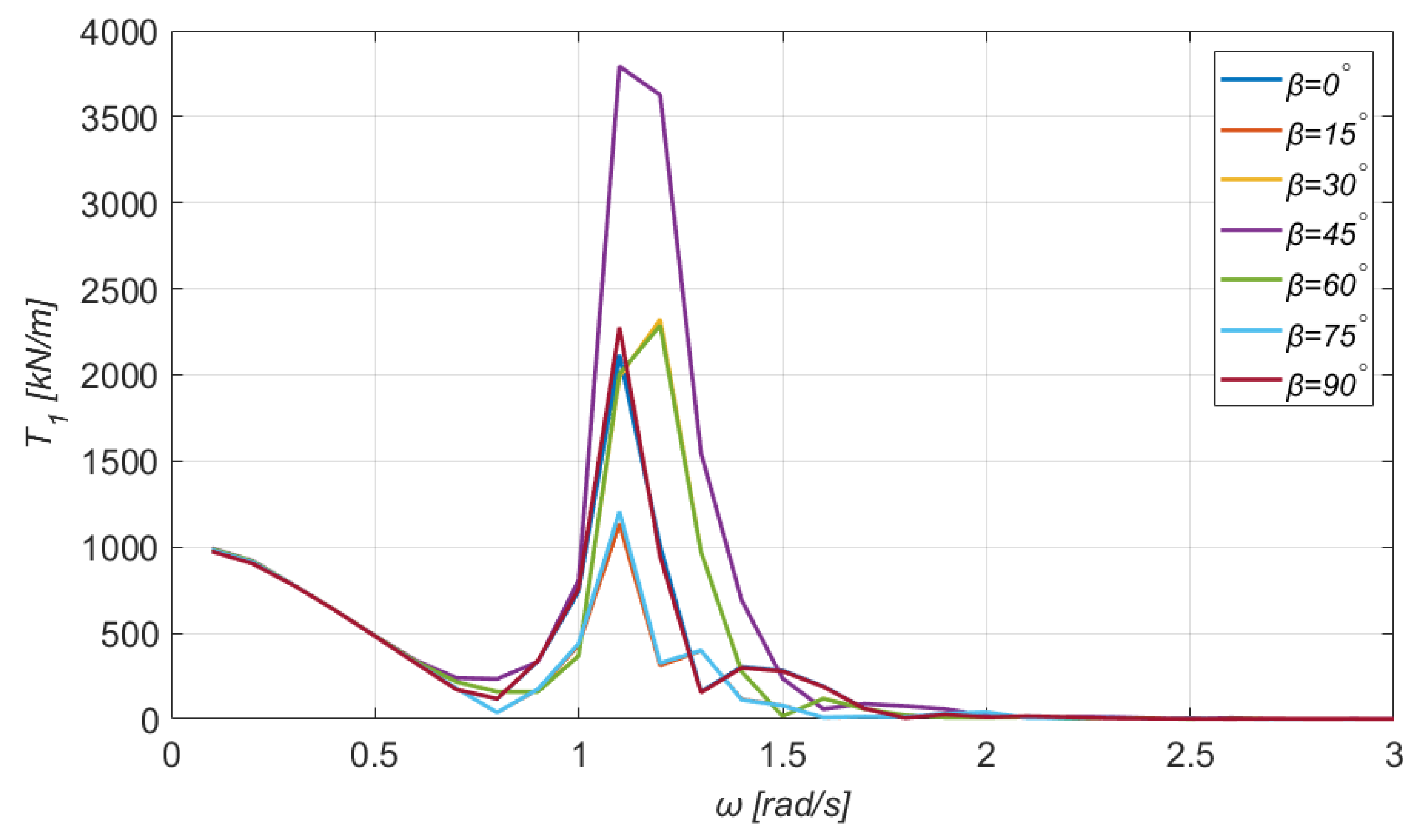
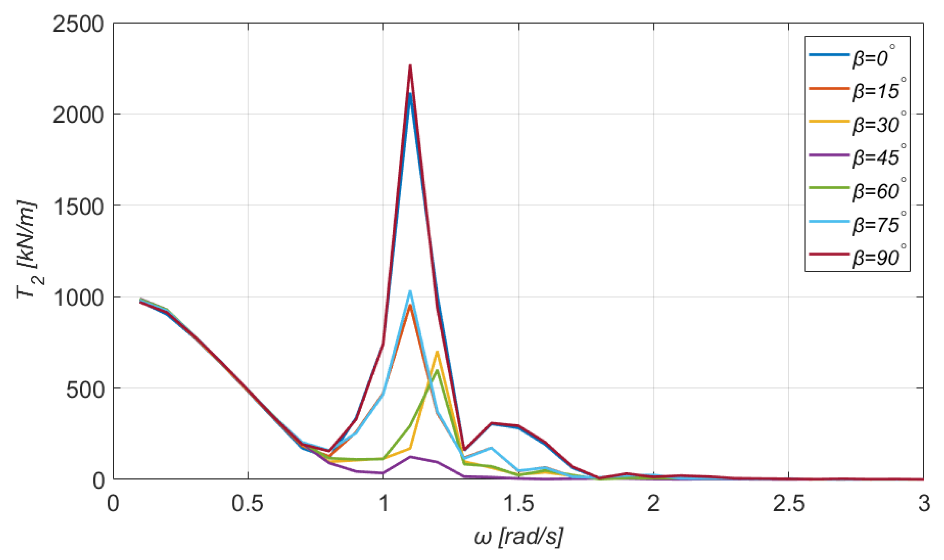
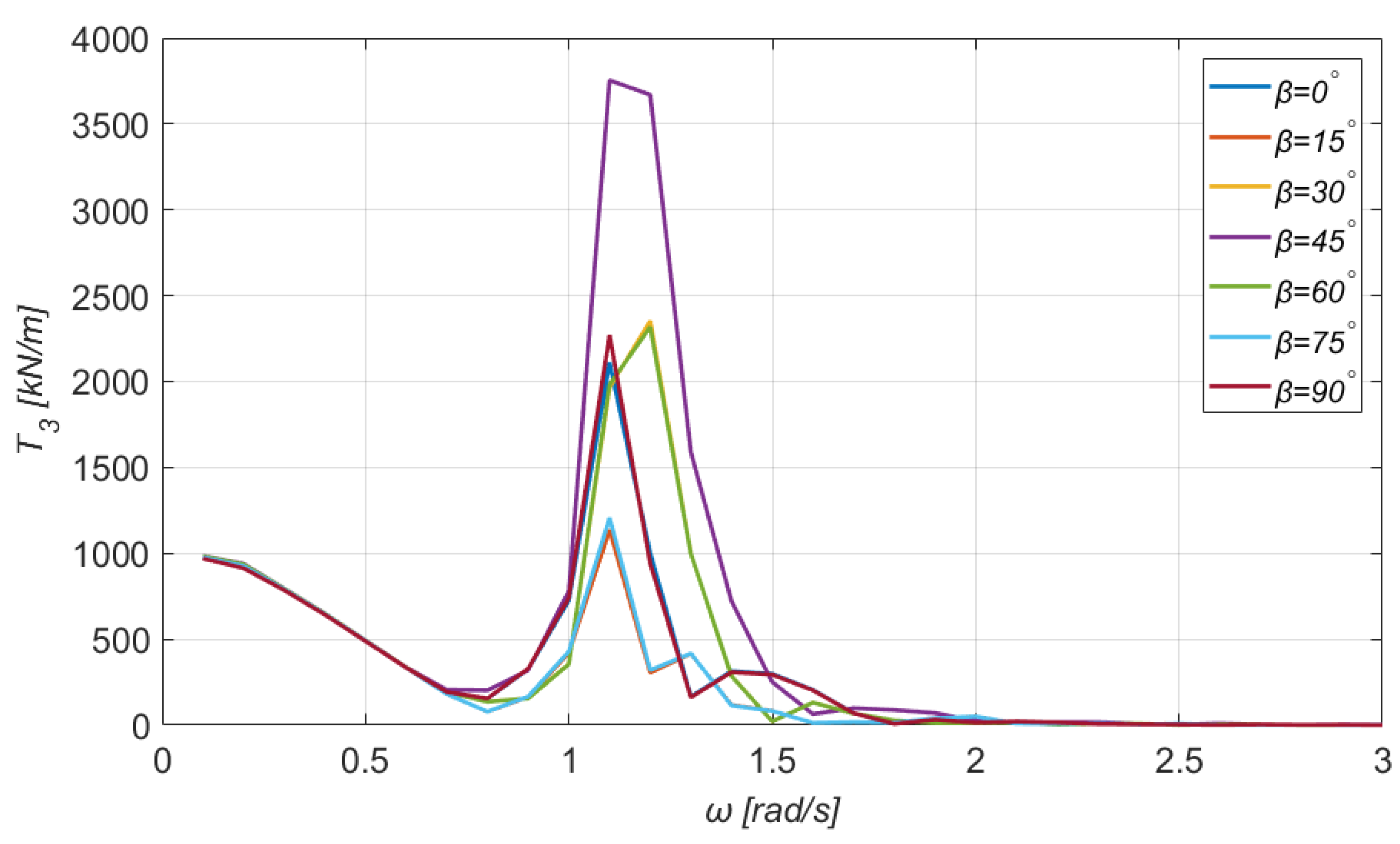
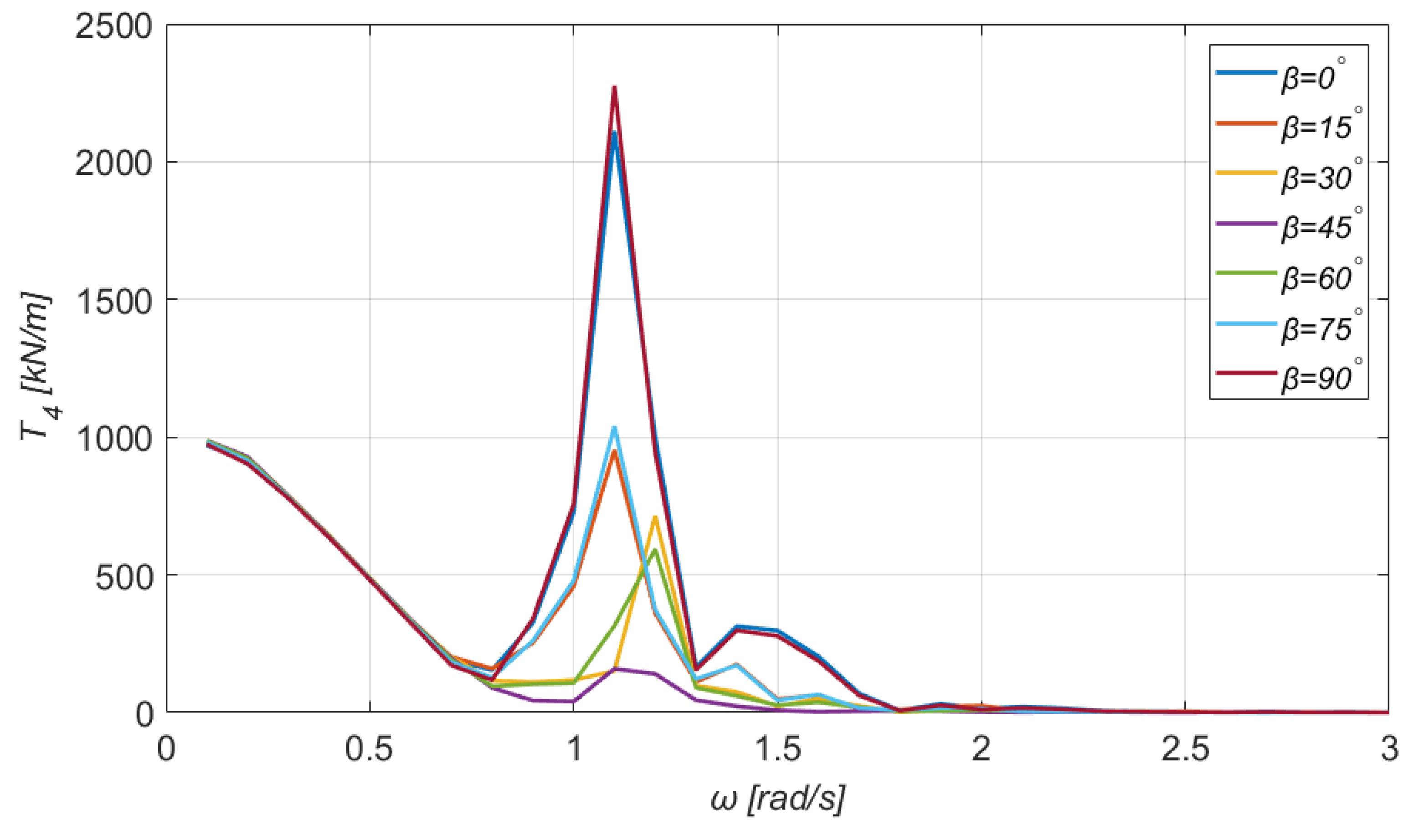
7. Calculation of the Total Mooring Tensions
In this section, the total mooring tensions at the top of each tendon are given in Figure 22, Figure 23, Figure 24 and Figure 25. With a careful observation of Figure 22 and Figure 23, we immediately notice that the curves of and which correspond to a completely horizontal direction of the incoming wave () are identical, as expected.
Figure 22.
Total mooring forces at the first tendon of the TLP.
Figure 23.
Total mooring forces at the second tendon of the TLP.
Figure 24.
Total mooring forces at the third tendon of the TLP.
Figure 25.
Total mooring forces at the fourth tendon of the TLP.
Similar deductions can be obtained for different angles as well, owing to the double symmetry of the rectangular floating structure, along the plane. Moreover, the values of the mooring tensions at the first and third branch (see Figure 22 and Figure 24) are considerably higher, compared to the second and fourth. Furthermore, it is interesting to mention that the maximum value of the tension at each tendon is obtained for the angular frequency . Finally, the tension at the first and third tendon is higher when the angle of the incoming wave is , whereas at the second and fourth, the tension is higher when .
8. Discussion and Conclusions
The purpose of this study was to formulate and solve the coupled hydroaeroelastic problem for a TLP floating WT in the frequency domain. The examined floating structure is rectangular. The hydrodynamic problem was solved by exploiting the method of matched axisymmetric eigenfunction expansions and the physical idea of multiple scattering. The contribution of the WT to the formulation of the dynamic equation of motion and its coupling to the floater was discussed sufficiently. Numerical results concerning the exciting forces and bending moments acting on the floating structure, along with the added masses and damping coefficients and the RAOs of the floater’s motions, have been presented. Moreover, the shear forces and moments at the interconnection of the WT tower with the floating structure have been evaluated. In addition, particular attention was paid to the tension at each branch of the TLP mooring system. Finally, the effect of the angle of wave incidence and of the angular frequency on the maximum values of the examined physical quantities has been examined in detail.
Author Contributions
Conceptualization, S.A.M. and T.P.M.; methodology, T.P.M.; software, S.A.M. and T.P.M.; validation, T.D.T.; investigation, T.P.M. and T.D.T.; writing—original draft preparation, T.P.M.; writing—review and editing, S.A.M., I.K.C., T.P.M. and T.D.T.; visualization, T.P.M. and T.D.T.; supervision, S.A.M. and I.K.C. All authors have read and agreed to the published version of the manuscript.
Funding
This research has been financed by the project FHMES: Floating Hybrid Mooring Wind Turbine Energy System. This project has received funding from the Hellenic Foundation for Research and Innovation (HFRI) and the General Secretariat for Research and Technology (GSRT), under grant agreement No 720 [61/5047].
Institutional Review Board Statement
Not applicable.
Informed Consent Statement
Not applicable.
Data Availability Statement
Not applicable.
Conflicts of Interest
The authors declare no conflict of interest.
Abbreviations
| TLP | Tension-leg platform |
| RAO | Response amplitude operator |
| WT | Wind turbine |
| OWC | Oscillating water column |
| DOF | Degrees of freedom |
| SWL | Still water level |
| CM | Center of mass |
| NUBO | Number of bodies |
References
- Tu, Y.; Cheng, Z.; Muskulus, M. A review of slamming load application to offshore wind turbines from an integrated perspective. Energy Procedia 2017, 137, 346–357. [Google Scholar] [CrossRef]
- Woo, C.; Chun, I.; Navaratnam, C.U.; Shim, J. Numerical analysis of dynamic response of jacket structures subject to slamming forces by breaking waves. Int. J. Nav. Arch. Ocean Eng. 2017, 9, 404–417. [Google Scholar] [CrossRef]
- Nielsen, F.G.; Hanson, T.D.; Skaare, B. Integrated dynamic analysis of floating offshore wind turbines. In Proceedings of the 25th International Conference on Offshore Mechanics and Arctic Engineering, Hamburg, Germany, 4–9 June 2006; OMAE2006-92291. ASME: New York, NY, USA, 2006; pp. 671–679. [Google Scholar]
- Skaare, B.; Hanson, T.D.; Nielsen, F.G.; Yttervik, R.; Hansen, A.M.; Thomsen, K.; Larsen, T.J. Integrated dynamic analysis of floating offshore wind turbines. In Proceedings of the European Wind Energy Conference and Exhibition (EWEC 2007), Milan, Italy, 7–10 May 2007; European Wind Energy Association: Brussels, Belgium, 2007. [Google Scholar]
- Utsunomiya, T.; Sato, T.; Matsukuma, H.; Yago, K. Experimental validation for motion of a spar-type floating offshore wind turbine using 1/22.5 scale model. In Proceedings of the 28th International Conference on Ocean, Offshore and Arctic Engineering, Honolulu, HI, USA, 31 May–5 June 2009; OMAE2009-79695. ASME: New York, NY, USA, 2009; pp. 951–959. [Google Scholar]
- Karimirad, M.; Moan, T. Extreme structural dynamic response of a spar type wind turbine. In Proceedings of the 29th International Conference on Ocean, Offshore and Arctic Engineering, Shanghai, China, 6–11 June 2010; OMAE2010-20044. ASME: New York, NY, USA, 2010; pp. 303–312. [Google Scholar]
- Mazarakos, T.P.; Mavrakos, S.A. Experimental investigation on mooring loads and motions of a Spar Buoy floating wind turbine. In Proceedings of the 3rd Offshore Energy and Storage Symposium (OSES 2016), Valletta, Malta, 13–15 July 2016. [Google Scholar]
- Mazarakos, T.P.; Mavrakos, S.A. Hydrodynamic loading of a Spar Buoy floating wind turbine in irregular waves. In Proceedings of the 12th Panhellenic Symposium of Oceanography and Fisheries, Corfu, Greece, 30 May–3 June 2018. [Google Scholar]
- Mazarakos, T.P.; Mavrakos, S.A.; Soukissian, T.H. Wave loading and wind energy of a Spar Buoy floating wind turbine. In Proceedings of the 14th International Conference on Ecological Vehicles and Renewable Energies (EVER 2019), Monte-Carlo, Monaco, 8–10 May 2019. [Google Scholar]
- Jonkman, J.M.; Buhl, M.L., Jr. Loads analysis of a floating offshore wind turbine using fully coupled simulation. In Proceedings of the WindPower Conference and Exhibition, Los Angeles, CA, USA, 3–6 June 2007. [Google Scholar]
- Wayman, E.N.; Sclavounos, P.D.; Butterfield, S.; Jonkman, J.M.; Musial, W. Coupled dynamic modeling of floating wind turbine systems. In Proceedings of the Offshore Technology Conference, Houston, TX, USA, 1–4 May 2006. [Google Scholar]
- Iijima, K.; Kim, J.; Fujikubo, M. Coupled aerodynamic and hydroelastic analysis of an offshore floating wind turbine system under wind and wave loads. In Proceedings of the 29th International Conference on Ocean, Offshore and Arctic Engineering, Shanghai, China, 6–11 June 2010; OMAE2010-20772. ASME: New York, NY, USA, 2010; pp. 241–248. [Google Scholar]
- Mazarakos, T.P.; Manolas, D.; Mavrakos, S.A. Design and Hydro-aero-elastic Modeling of a Multi Leg Mooring Concept for Floating Wind Turbine Applications. In Proceedings of the 16th International Conference on Ecological Vehicles and Renewable Energies (EVER 2021), Monte-Carlo, Monaco, 5–7 May 2021. [Google Scholar]
- Mazarakos, T.P.; Manolas, D.; Mavrakos, S.A. Design and hydro-aero-elastic modeling of a TLP concept for floating Wind Turbine applications. In Proceedings of the 31st International Ocean and Polar Engineering Conference (ISOPE 2021), Rhodes, Greece, 20–25 June 2021. [Google Scholar]
- Withee, J.E.; Sclavounos, P.D. Fully coupled dynamic analysis of a floating wind turbine system. In Proceedings of the 8th World Renewable Energy Congress, Denver, CO, USA, 28 August–3 September 2004. [Google Scholar]
- Weinzettel, J.; Reenas, M.; Solli, C.; Hertwich, E.G. Life cycle assessment of a floating offshore wind turbine. Renew. Energy 2009, 34, 742–747. [Google Scholar] [CrossRef]
- Bae, Y.H.; Kim, M.H.; Shin, Y.S. Rotor-floater-mooring coupled dynamic analysis of mini TLP-type offshore floating wind turbines. In Proceedings of the 29th International Conference on Ocean, Offshore and Arctic Engineering, Shanghai, China, 6–11 June 2010; OMAE2010-20555. ASME: New York, NY, USA, 2010; pp. 491–498. [Google Scholar]
- Mazarakos, T.P.; Manolas, D.; Grapsas, T.; Mavrakos, S.A.; Riziotis, V.; Voutsinas, S. Conceptual Design and advanced hydro-aero-elastic modelling of a TLP concept for Floating Wind Turbine applications. In Proceedings of the 1st International Conference on Renewable Energies Offshore (RENEW), Lisbon, Portugal, 24–26 November 2014. [Google Scholar]
- Mazarakos, T.P.; Konispoliatis, D.N.; Mavrakos, S.A. Design of a TLP floating structure concept for combined wind and wave energy exploitation. In Proceedings of the 2nd International Conference on Renewable Energies Offshore (RENEW), Lisbon, Portugal, 24–26 October 2016. [Google Scholar]
- Mazarakos, T.P.; Charalambous, M. Experimental investigation of the wave run up on a TLP floating wind turbine. In Proceedings of the 3rd International Conference Energy in Transportation, Athens, Greece, 3 November 2018. [Google Scholar]
- Mazarakos, T.P.; Mavrakos, S.A. Experimental Investigation on Mooring Loads and Motions of A TLP Floating Wind Turbine. in the Special Session on Offshore and Marine Renewable Energy: Conversion and Transmission. In Proceedings of the 12th International Conference on Ecological Vehicles and Renewable Energies (EVER 2017), Monte-Carlo, Monaco, 11–13 April 2017. [Google Scholar]
- Mazarakos, T.P.; Konispoliatis, D.N.; Manolas, D.I.; Mavrakos, S.A.; Voutsinas, S. Coupled hydro-aero-elastic analysis of a floating structure for offshore wind and wave energy sources exploitation. In Proceedings of the 12th International Conference on Stability of Ships and Ocean Vehicles (12th STAB), Glasgow, UK, 14–19 June 2015. [Google Scholar]
- Mazarakos, T.P.; Konispoliatis, D.N.; Manolas, D.I.; Voutsinas, S.G.; Mavrakos, S.A. Modelling of an Offshore Multi-Purpose Floating Structure Supporting a Wind Turbine Including Second-Order Wave Loads. In Proceedings of the 11th European Wave and Tidal Energy Conference (11th EWTEC), Nantes, France, 6–11 September 2015. [Google Scholar]
- Evans, D.V.; Porter, R. Efficient calculation of hydrodynamic properties of O.W.C. type devices. J. Offshore Mech. Arct. Eng. 1997, 119, 210–218. [Google Scholar] [CrossRef]
- Aubault, A.; Alves, M.; Sarmento, A.; Roddier, D.; Peiffer, A. Modeling of an oscillating water column on the floating foundation windfloat. In Proceedings of the 30th International Conference on Ocean, Offshore and Arctic Engineering, Rotterdam, The Netherlands, 19–24 June 2011; OMAE2011-49014. ASME: New York, NY, USA, 2011; pp. 235–246. [Google Scholar]
- Mazarakos, T.P.; Konispoliatis, D.; Katsaounis, G.; Polyzos, S.; Manolas, D.; Voutsinas, S.; Soukissian, T.; Mavrakos, S. Numerical and experimental studies of a multi-purpose floating TLP structure for combined wind and wave energy exploitation. Mediterr. Mar. Sci. 2019, 20, 745–763. [Google Scholar] [CrossRef] [Green Version]
- Shimada, K.; Ohyama, T.; Miyakawa, M.; Ishihara, T.; Phuc, P.V.; Sukegawa, H. A study on a semisubmersible floating offshore wind energy conversion system. In Proceedings of the 17th International Offshore and Polar Engineering Conference (ISOPE 2007), Lisbon, Portugal, 1–6 July 2007.
- Ishihara, T.; Phuc, P.V.; Sukegawa, H.; Shimada, K.; Ohyama, T. A study on the dynamic response of a semi-submersible floating offshore wind turbine system Part 1: A water tank test. In Proceedings of the 12th International Conference on Wind Engineering (ICWE 12), Cairns, Australia, 1–6 July 2007. [Google Scholar]
- Cermelli, C.; Roddier, D.; Aubault, A. WINDFLOAT: A floating foundation for offshore wind turbines Part II: Hydrodynamics analysis. In Proceedings of the 28th International Conference on Ocean, Offshore and Arctic Engineering, Honolulu, HI, USA, 31 May–5 June 2009; OMAE2009-79231. ASME: New York, NY, USA, 2009; pp. 135–143. [Google Scholar]
- Manolas, D.I.; Riziotis, V.A.; Voutsinas, S.G. Assessing the importance of geometric non-linear effects in the prediction of wind turbine blade loads. J. Comput. Nonlinear Dyn. 2015, 10, 041008. [Google Scholar]
- Mazarakos, T.P.; Konispoliatis, D.N.; Katsaounis, G.; Polyzos, S.; Manolas, D.; Voutsinas, S.; Mavrakos, S.A. Numerical and experimental studies of an offshore multi-purpose floating structure supporting a wind turbine. In Proceedings of the 12th European Wave and Tidal Energy Conference (12th EWTEC), Cork, Ireland, 27 August–1 September 2017. [Google Scholar]
- Tran, T.; Kim, D.; Song, J. Computational fluid dynamic analysis of a floating offshore wind turbine experiencing platform pitching motion. Energies 2014, 7, 5011–5026. [Google Scholar] [CrossRef]
- Tran, T.T.; Kim, D.-H. A CFD study into the influence of unsteady aerodynamic interference on wind turbine surge motion. Renew. Energy 2016, 90, 204–228. [Google Scholar] [CrossRef]
- Wang, X.; Ye, Z.; Kang, S.; Hu, H. Investigations on the unsteady aerodynamic characteristics of a horizontal-axis wind turbine during dynamic yaw process. Energies 2019, 12, 3124. [Google Scholar] [CrossRef] [Green Version]
- Chen, Z.; Wang, X.; Guo, Y.; Kang, S. Numerical analysis of unsteady aerodynamic performance of floating offshore wind turbine under platform surge and pitch motions. Renew. Energy 2021, 163, 1849–1870. [Google Scholar] [CrossRef]
- Mavrakos, S.A. User’s Manual for the Software HAMVAB; School of Naval Architecture and Marine Engineering, Laboratory for Floating Structures and Mooring Systems: Athens, Greece, 1996. [Google Scholar]
- Mavrakos, S.A. Hydrodynamic coefficients for groups of interacting vertical axisymmetric bodies. Ocean Eng. 1991, 18, 485–515. [Google Scholar] [CrossRef]
- Bak, C.; Zahle, F.; Bitsche, R.; Kim, T.; Yde, A.; Henriksen, L.C.; Natarajan, A.; Hansen, M.H. Description of the DTU 10 MW Reference Wind Turbine; In the Wind Energy Report-I-0092; DTU Wind Energy: Roskilde, Denmark, 2013. [Google Scholar]
- Newman, J. The exciting forces on fixed bodies in wave. J. Ship Res. 1962, 6, 10–17. [Google Scholar] [CrossRef]
- Mazarakos, T.P.; Konispoliatis, D.N.; Mavrakos, S.A. Loads on the brace system of an offshore floating structure. In Proceedings of the 13th International Marine Design Conference, Helsinki, Finland, 10–14 June 2018; Kujala, P., Lu, L., Eds.; Taylor & Francis Group: London, UK, 2018. [Google Scholar]
Publisher’s Note: MDPI stays neutral with regard to jurisdictional claims in published maps and institutional affiliations. |
© 2022 by the authors. Licensee MDPI, Basel, Switzerland. This article is an open access article distributed under the terms and conditions of the Creative Commons Attribution (CC BY) license (https://creativecommons.org/licenses/by/4.0/).