Abstract
Steering wheel angle is an important and essential parameter of the navigation control of autonomous wheeled vehicles. At present, the combination of rotary angle sensors and four-link mechanisms is the main sensing approach for steering wheel angle with high measurement accuracy, which is widely adopted in autonomous agriculture vehicles. However, in a complex and challenging farmland environment, there are a series of prominent problems such as complicated installation and debugging, spattered mud blocking the parallel four-bar mechanism, breakage of the sensor wire during operation, and separate calibrations for different vehicles. To avoid the above problems, a novel dynamic measurement method for steering wheel angle is presented based on vehicle attitude information and a non-contact attitude sensor. First, the working principle of the proposed measurement method and the effect of zero position error on measurement accuracy and path tracking are analyzed. Then, an optimization algorithm for zero position error of steering wheel angle is proposed. The experimental platform is assembled based on a 2ZG-6DM rice transplanter by software design and hardware modification. Finally, comparative tests are conducted to demonstrate the effectiveness and priority of the proposed dynamic sensing method. Experimental results show that the average absolute error of the straight path is 0.057° and the corresponding standard deviation of the error is 0.483°. The average absolute error of the turning path is 0.686° and the standard deviation of the error is 0.931°. This implies the proposed dynamic sensing method can accurately realize the collection of the steering wheel angle. Compared to the traditional measurement method, the proposed dynamic sensing method greatly improves the measurement reliability of the steering wheel angle and avoids complicated installation and debugging of different vehicles. The separate calibrations for different vehicles are not needed since the proposed measurement method is not dependent on the kinematic models of the vehicles. Given that the attitude sensor can be installed at a higher position on the wheel, sensor damage from mud blocking and the sensor wire breaking is also avoided.
1. Introduction
Precision agriculture has undergone rapid development in the past decades. The goal of precision agriculture is beneficial to productivity and environmental conditions and also to improving the working conditions of agricultural producers [1,2,3]. Autonomous agricultural machinery can replace agricultural producers to perform monotonous work and thus reduce the labor intensity of operations.
In recent years, autonomous agricultural machinery covering plowing, planting, management, and harvesting has been developed in China [4,5,6,7,8], and several runs of field demonstration tests have been carried out. However, it has not yet realized long-term continuous and reliable operations, which are limited by many factors such as the unreliability of components and the inability of navigation control algorithms to adapt to the complex and dynamic farmland environment [9,10,11,12].
For the automatic navigation system of autonomous agricultural machinery, the steering wheel angle is one of the key parameters of the navigation control system [13] and has an important influence on the field operation quality and performance of autonomous wheeled vehicles. Angle acquisition method and accuracy have an important influence on navigation accuracy and reliability of the navigation system.
Currently, two kinds of sensors are commonly used to sense the steering angle [14]: one is the absolute angular displacement sensor and the other is a relative angle sensor such as the MEMS gyroscope, which obtains the angle by integrating the sensor output. The absolute angular displacement sensors with corresponding mechanical structures are assembled with the autonomous agricultural machinery [2,3,8,15,16,17,18]. The common characteristic is that the absolute angular sensor needs more connections and a complex mechanical structure, which has problems associated with inconvenient installation, checks, and maintenance, as well as poor reliability. Most of the existing unmanned wheeled vehicles adopt a combination of the angle sensor and the four-bar mechanism to obtain the steering wheel angle. However, there are some prominent problems, such as complicated installation and debugging, blocking of the parallel four-link mechanism by spattering soil, the sensor wire getting damaged during operation, and the need for separate calibrations when installing different vehicles (Figure 1), which lead to poor operational reliability and low efficiency of the unmanned agricultural machinery system. To solve these problems, the gyroscope has been used to sense the steering angle in extensive research [19,20,21,22]. However, the output signals contain zero bias, drift [14], and cumulative error over time [18,19]. Different filtering methods such as the Kalman filter [19,20,21,22] and autoregressive and moving average time-series model [22] are adopted to reduce noise. It is regrettable, however, that these methods depend on the kinematic model of the vehicles.
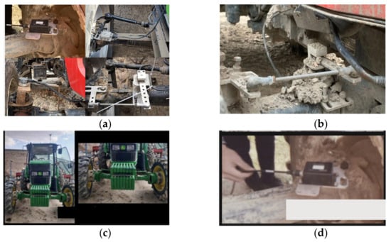
Figure 1.
Problems of steering angle measurement. (a) Complex installation; (b) blocked by spattering soil; (c) recalibration when installing on different vehicles; (d) damage of sensor wire.
To overcome the complex mechanical structure and multiple connections of the absolute angular sensors and avoid the development of the vehicle kinematic model, a novel dynamic measurement method for steering wheel angle is presented based on vehicle attitude information and a non-contact attitude sensor. First, the working principle of the proposed measurement method and the effect of zero position error on measurement accuracy and path tracking are analyzed. Then, an optimization method for zero position error of steering wheel angle is proposed.
Main contribution: Compared to previous research, the contribution of this study is providing a dynamic measurement method for steering wheel angle which hardly relies on the complicated vehicle kinematics model and error equation of steering wheel angle. Additionally, it has the advantages of convenient installation, checks, and maintenance, as well as high reliability. Furthermore, the installation of the angle sensor is flexible and it can be installed on the steering component. This provides good solutions for low-chassis vehicles such as rice transplanters and can prevent water from entering the sensor and reducing sensor performance or causing sensor damage since the sensor is installed at a higher position. Figure 1 shows four cases: complex installation (Figure 1a), blockage by spattering soil (Figure 1b), recalibration when installing on different vehicles (Figure 1c), and damaged angle sensor wire (Figure 1d).
The rest of the paper is organized as follows: first, a non-contact measurement principle of steering wheel angle based on an attitude sensor is introduced in Section 2. Second, an analysis and optimization method of zero position error for steering wheel angle is presented in Section 3. Subsequently, results and discussion are given for the testing and validation of the proposed approaches in Section 4. Finally, concise concluding remarks and a description of future works are presented in Section 5.
Literature Review
Nowadays, two types of sensors are commonly used for steering angle measurement. One is the absolute angular displacement sensor, the other is a relative angular sensor such as a gyroscope, which obtains the angle by integrating the sensor’s output. The absolute angular displacement sensor is widely used in autopilot systems because of its advantages of accurate measurement. A comparative test between displacement and four-bar indirect measurement methods for tractor steering wheel angle is conducted [13]. According to the measurement principles of two kinds of methods, the steering angle measurement models are established. Although the proposed measurement methods obtained accurate measurement results, the complex mechanical structure is still covered. An absolute rotary encoder is used to sense the steering angle of an autonomous rice transplanter [23]. A precise and low-cost non-contact steering angle sensor is developed based on a giant magnetoresistance sensor [19]. In addition, the absolute rotary encoders are adopted by extensive autonomous guidance systems, such as rice transplanters [15,16,17,24] and tractors [4,5,6,9]. However, the absolute angular sensor needs a complex mechanical structure [25,26], so it is difficult to maintain and replace, which can cause malfunction and manpower waste [14,18,27]. Given this, a relative angular sensor such as a gyroscope which has a small size and can be flexibly installed and replaced is welcomed to sense the front steering angle. Although the gyroscope has the advantage of small volume and easy installation and replacement, the output signals contain zero bias, drift [24], and cumulative error over time [19]. To improve the sensing accuracy of the steering angle, these zero bias, drift, and cumulative errors need to be reduced or eliminated as much as possible. An autoregressive and moving average time-series model for the gyroscope drift signal is built and a Kalman filter is used to filter this drift signal [22]. However, although this method can decrease the influence of random drift, the error caused by zero bias still accumulates over time. To correct the angle error caused by zero bias, a steering angle adaptive estimation system based on GNSS and MEMS gyro is developed and an adaptive Kalman filter is used to correct the accumulative errors of the gyroscope data [18]. However, the vehicle kinematics model and error equation of steering angle are needed to estimate the steering angle.
A measuring system of steering wheel angle was proposed based on a GNSS attitude and motor encoder [21]. The expected angle of the steering wheel is obtained by the measurement of a GNSS attitude and kinematic model. The variation value of steering angle is calculated by using the transfer model of motor steering speed and full hydraulic steering valve. The real-time steering angle of the vehicle steering wheel is obtained and filtered by the Kalman filter. The standard deviation was less than 0.91° in straight-line tracking, while the deviation was 2.56° in the curved-path tracking. However, this method depends on the accurate kinematic model of the vehicle. The comparison between the main literature and this paper is shown in Table 1. It can be found from Table 1 that the proposed measurement method is not dependent on the kinematic model of the vehicle and the error equation of the steering wheel angle. Moreover, the complex mechanical structure is not needed.

Table 1.
The comparison between the main literature and this paper.
2. Method
2.1. Non-Contact Measurement Principle of Steering Wheel Angle Based on Attitude Sensor
To better understand the dynamic measurement method for steering wheel angle, it is necessary to introduce the installation method of the non-contact sensor and steering angle measurement principle.
2.2. Installation of Non-Contact Sensor
Figure 2 shows the installation diagram of the steering wheel angle sensor using a non-contact sensor to measure the steering wheel angle. Compared with the contact measurement method, the non-contact measurement method has the following advantages: (1) the installation method is simple, without complex mechanical mechanism design, and the installation accuracy requirements are low; (2) the non-contact sensor has a higher waterproof grade, and the corresponding waterproof performance is better; (3) there is no need for separate calibration when installing on different vehicles, saving labor and effort. However, the non-contact measurement method needs to combine the attitude information of the vehicle body and carry out mathematical operations to obtain the actual wheel angle. As shown in Figure 2b, the angle sensor is welded and threaded onto the steering post of the right steering wheel of the vehicle. It should be noted that the installation of the angle sensor is flexible and it should just be installed on the steering component. This is significant for low-chassis vehicles such as rice transplanters and can prevent water from entering the sensor and causing degradation of the sensor performance or sensor damage. The attitude sensor (LPMS-IG1, Guangzhou Alubi Electronic Technology Co., Ltd., Guangzhou, China) as shown in Figure 2a is selected for sensing the steering wheel angle in this study, and the corresponding main technical parameters are shown in Table 2.
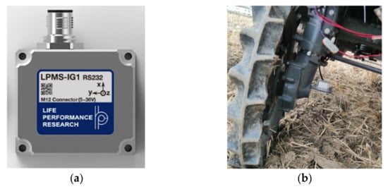
Figure 2.
Installation diagram of steering wheel angle sensor. (a) Steering wheel angle sensor. (b) Installation of steering wheel angle sensor.
Table 2.
Main technical parameters.
During the driving process of the vehicle, the value from the non-contact angle sensor installed on the steering wheel represents not only the value of the steering wheel angle but also includes the heading information of the vehicle body. Therefore, in practical application, the actual value of the steering wheel angle is calculated by the angle value from the non-contact angle sensor and the heading information from the body attitude sensor.
2.3. Angle Measurement Principle
For ease of explanation, this paper uses a two-wheel vehicle model to elaborate, and the non-contact measurement principle of steering wheel angle is shown in Figure 3. , , and represent the values, in the initial position, of the steering wheel angle sensor, vehicle body attitude sensor, and actual value of the steering wheel angle, respectively. After traveling some distance, the vehicle body will produce offset. At this moment, the value from the steering wheel angle sensor represents the included angle between the steering wheel and the initial direction, rather than the actual value of the steering wheel. is the intersection angle between the vehicle body and initial azimuth, namely vehicle heading. The actual value of the steering wheel angle should be the angle between the direction of the wheel and the direction of the body.
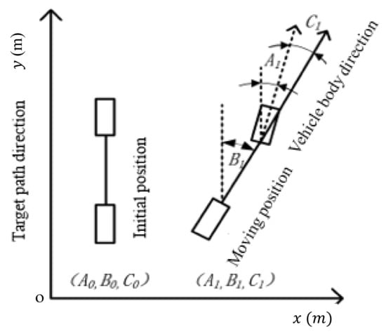
Figure 3.
Schematic diagram of non-contact measuring principle.
According to the direction of the wheel, the direction of the body, the direction of the target path, and the initial direction of the vehicle during the traveling process of the vehicle, four cases are discussed (Figure 4). The recorded values A from the steering wheel sensor and B from the body posture sensor range from −180°~180°. The values increase when rotated counterclockwise and decrease when rotated clockwise. The angle B is the included angle between the target path direction (initial position direction) and the vehicle body direction, which is the variation quantity of the heading angle. The heading angle is acquired by the GPS/Beidou navigation system mounted on the autonomous vehicles.
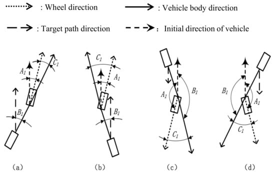
Figure 4.
Schematic diagram of four common situations. (a) The wheel and the vehicle body are both to the right relative to the initial direction; (b) the direction of the wheel is to the right relative to the initial direction while the direction of the body is to the left relative to the initial direction; (c) the direction of the wheel is to the left relative to the initial direction while the direction of the body is to the right relative to the initial direction; (d) the wheel and the vehicle body are both to the left relative to the initial direction.
The non-contact sensor has the characteristics of power-on return to zero, that is, the value from the sensor is always zero when powering. Therefore, when using a non-contact sensor to measure the steering wheel angle, the steering wheel should first be artificially rotated to a parallel state to the body. However, the absolute parallel between the wheel and the vehicle body is difficult to guarantee. This will inevitably lead to zero error, and then affect the path-tracking accuracy. In addition, in each manual adjustment, this zero position error changes dynamically with the variation of the parallelism between the wheel and the body. This means that the traditional zero position error elimination method is hardly used. Thus, it is necessary to propose a new zero position error elimination method. Therefore, to reduce the influence of such errors on path tracking, an optimization method is proposed in this study to obtain the actual steering wheel angle value by integrating the sensor values of the body attitude angle and the steering wheel angle.
By analyzing the four cases shown in Figure 4, the corresponding analysis can be summarized as:
(a) The wheel and the vehicle body are both to the right relative to the initial direction, thus .
(b) The direction of the wheel is to the right relative to the initial direction while the direction of the body is to the left relative to the initial direction, under this circumstance. For cases (a) and (b), , . The actual steering wheel angle can be described as
(c) The direction of the wheel is to the left relative to the initial direction while the direction of the body is to the right relative to the initial direction. Under this circumstance, and , . Thus,
(d) The wheel and the vehicle body are both to the left relative to the initial direction, thus and , . Thus,
According to the above analysis, the resolver flowchart of the actual steering wheel angle is shown in Figure 5.
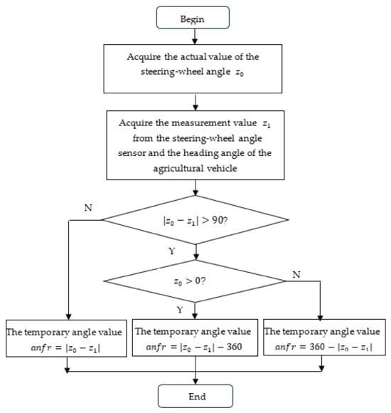
Figure 5.
Flowchart of angle value resolver.
In Figure 5, , , and are the temporary angle value, the actual value of the steering wheel angle, the measurement value from the steering wheel angle sensor, and the heading angle of the agricultural vehicle, respectively.
3. Analysis and Optimization Method of Zero Position Error for Steering Wheel Angle
According to the above analysis, under ideal conditions, the steering wheel is required to be completely parallel to the body before the sensor is powered on, and the calculated value is the real steering wheel angle. However, in actual application, it is impossible to manually rotate the steering wheel to a completely parallel state with the body, resulting in the deviation ∆δ between the steering wheel and the body (Figure 6) always existing and not being zero. However, the zero position error directly leads to the reduction of vehicle navigation control accuracy. Therefore, it is necessary to conduct the error analysis of the steering wheel angle and the optimization method of the zero position error.
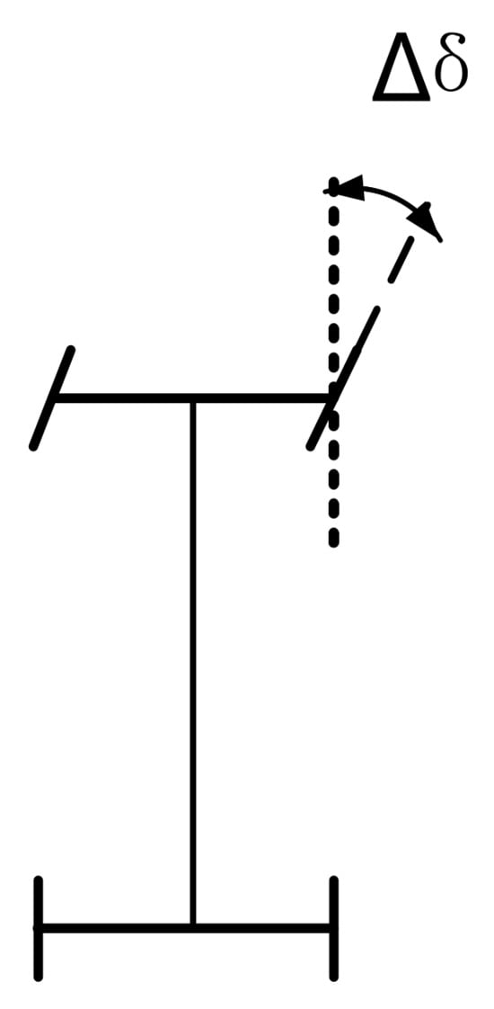
Figure 6.
Diagram of deviation between the steering wheel and vehicle body.
3.1. Error Analysis of Steering Wheel Angle
∆δ is the angle formed between the steering wheel of agricultural machinery and the body when the artificial alignment is finished, which can also be understood as the zero position error of the steering wheel angle. ∆δ has the same characteristics as the wheel angle, in which the left is positive and the right is negative. To explore the effect of zero position error on steering wheel angle, a simulation model is established by MATLAB (R2014a) in this paper. It is assumed that initial lateral deviation and heading deviation are 0.1 m and 0°, respectively. The vehicle speed is 0.8 m/s. The pure-pursuing algorithm is used as the navigation control of the vehicle and the forward-looking distance is set as 1.0 m. The simulation tests are conducted for three cases: ∆δ > 0, ∆δ < 0, and ∆δ = 0. The simulation results are shown in Figure 7.
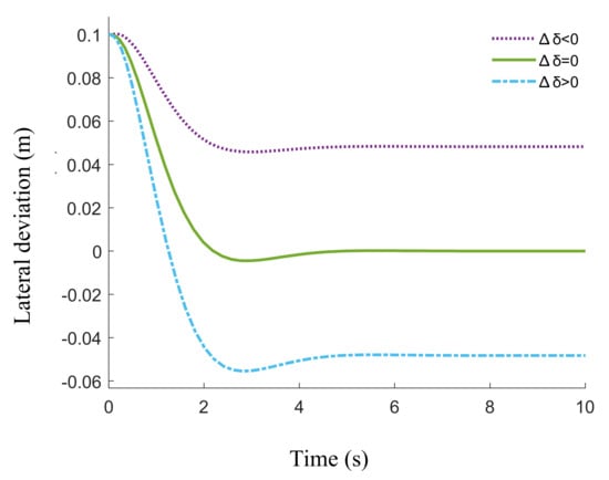
Figure 7.
Effect of deviation ∆δ on the lateral deviation in steady state.
The steering wheel angle can be expressed as
where and are respectively real steering wheel angle and steering wheel rotation angle with zero position error.
By combining Equation (2) with the simulation results from Figure 5, we can know = 0 at the zero of the sensors, that is, = ∆δ. When ∆δ > 0, the wheel is to the left, and the lateral deviation d < 0 in the steady state of the path tracking. The corresponding tracking trajectory is on the left of the driving direction of the target path. On the contrary, when ∆δ < 0, the wheel is to the right, and the lateral deviation d > 0 in the steady state of the path tracking. The corresponding tracking trajectory is on the right of the driving direction of the target path. The deviation values between the steering wheel and vehicle body are 4.6 cm, 0.6 cm, and 5.3 cm when ∆δ > 0, ∆δ = 0, and ∆δ < 0, respectively. It can be seen that the deviation ∆δ between the steering wheel and the body has an important effect on the lateral deviation when the vehicle tracks the target path to a steady state. Inspired by these analysis results, we can optimize the zero position error by using the lateral deviation in the steady state.
3.2. Optimization Method of Zero Position Error
Time multiplied by error integral is used to evaluate the magnitude and direction of the error, and the expression can be described as
where d(t) is the lateral deviation at time is the start time, is the step length, and, after many repeated tests, this paper takes 20. The detailed optimization steps are as follows.
(1) After the path tracking starts, the collected deviation data are integrated with a period of (100 ms), and Equation (6) is used to determine whether further optimization is needed. is determined by the step size and the deviation sampling frequency.
(2) Calculate the deviation grade and direction
where deg is used to indicate the degree of deviation, where a positive value indicates a right deviation.
(3) Adjust zero deviation based on deg
where ∈ [0.05, 0.2] indicates the adjustment step size, is the zero error after updating.
(4) Boundary treatment
According to Equation (9), determine whether is beyond the adjustable range [−].
where is the boundary of the adjustable range, which is generally set as .
(5) Update ∆δ according to Equation (10) and adopt Equation (4) to calculate the steering wheel angle and repeat the above steps.
Figure 8 shows the flowchart of zero error optimization.
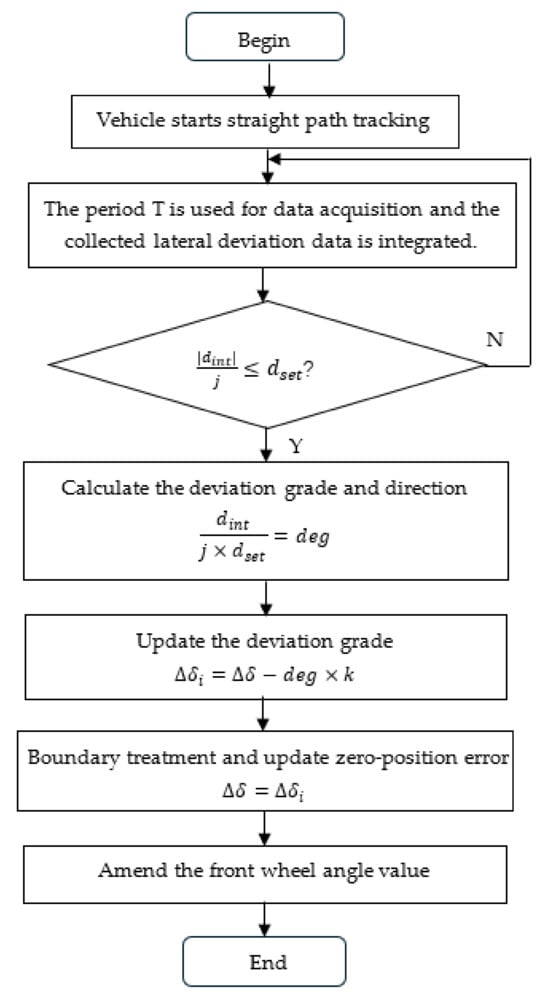
Figure 8.
Flowchart of zero error optimization method.
4. Results and Discussion
4.1. Test Platform
To test and validate the performance of the proposed dynamic measurement method for steering wheel angle, the field tests were conducted in the grain industrial park of Xinghua City, Jiangsu Province. A 23.86 m 15.10 m rectangular field was used for the experiment. The unevenness of paddy soil was not more than 10 cm. The four longitude and latitude coordinates of field vertices were acquired by the navigation module and converted into the current field coordinates. According to the operating swath of the rice transplanter, the field operation paths were automatically planned and autonomously generated. A six-row autonomous rice transplanter (NSPU-68CMD, Kubota Agricultural Machinery (Suzhou) Co., Ltd., Suzhou, China) as shown in Figure 9 is used as the experimental platform.
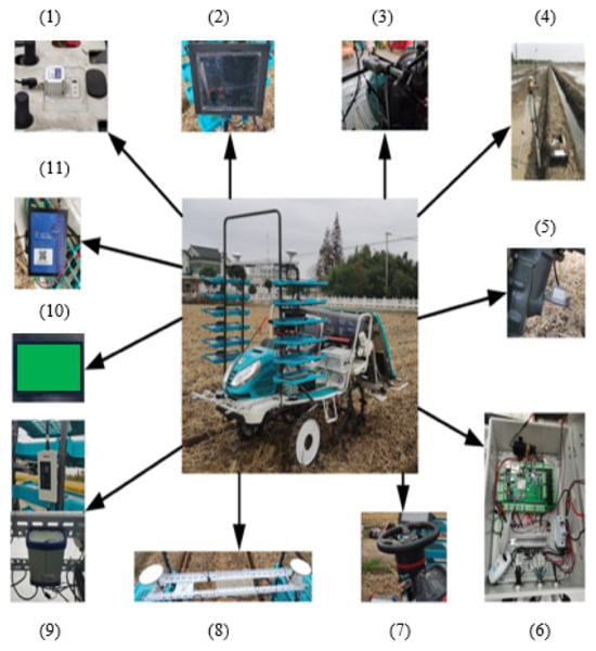
Figure 9.
Experimental platform. (1) Attitude sensor; (2) Navigation controller; (3) Push rod of gear; (4) Navigation base station; (5) Angle sensor; (6) Vehicle-mounted controller; (7) Electric steering wheel; (8) Navigation mobile station antenna; (9) Navigation data receiver; (10) Serial screen; (11) Data transmission module.
The combination navigation of BEIDOU and an inertial navigation system (INS) was adopted. A HUA XIN full band antenna, supporting a C201 receiver, and navigation reference station were selected as the navigation module. RTK horizontal positioning accuracy is ±2cm, and the data update rate is set as 5 Hz. The attitude sensor is a micro inertial sensor with an MTI-30 model manufactured by XENS of the Netherlands. The description of the software and main hardware materials of the experimental platform is summarized in Table 3. A more detailed description of the experimental platform can be found in Ref. [4] and is not repeated here.
Table 3.
Description of software and main hardware materials.
The proposed mechanism has been installed in the test platform and rigorous validation has been conducted in the straight and curvy road scenarios. Finally, a comparison study has been performed between the conventional relative angle sensor and the proposed mechanism to show the accuracy and effectiveness of the proposed mechanism in terms of error rate, stability, and deviation.
Meanwhile, the rotary angle sensor (DWQT-RS485-G/J, Beijing Tianhai Technology Co., Beijing, China) is installed on the left steering wheel by the designed fixed bracket (Figure 10), and the specific parameters are shown in Table 4. The connecting rod and the steering wheel steering shaft constituted a parallel four-bar mechanism, and the angle sensor was installed at the wheel steering trapezoid, which provided accurate angle data for the steering control of the transplanter.
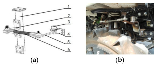
Figure 10.
Installation schematic diagram of angle sensor. (a) Structure diagram; (b) Installation drawing. 1. Steering shaft; 2. Trellis bar; 3. Angle sensor; 4. Fixed bracket; 5. Fixed link; 6. Ball tie rod.
Table 4.
Parameters of angle sensor.
4.2. Results
The path of straight and curved lines is shown in Figure 11. The route is completed by the autonomous rice transplanter, which executes a pure-pursuit control algorithm. The control algorithm is performed based on the steering angle from the measurement method in this study and the output of the conventional angle sensor is used as reference. The straight-line speed and turning speed are 0.8 m/s and 0.5 m/s, respectively. To exclude chance in the experiment, tests are repeated 5 times and the obtained angle values are averaged.
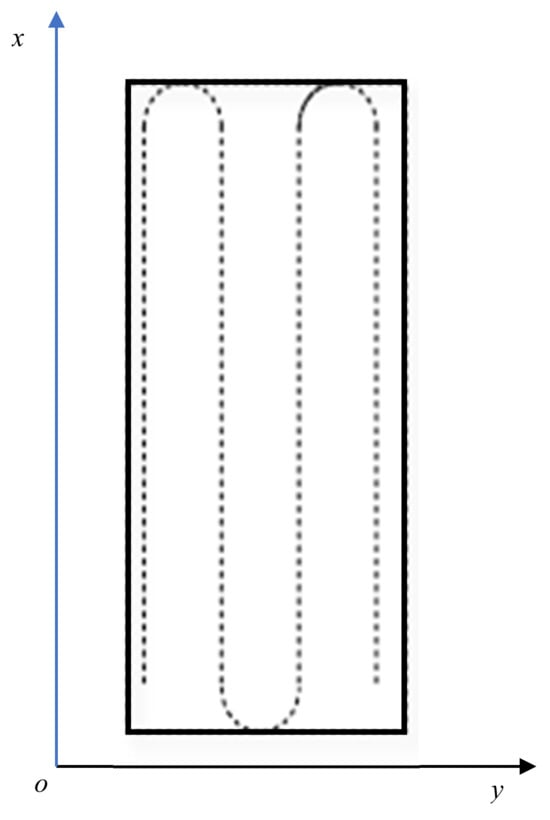
Figure 11.
Experiment path.
The autonomous rice transplanter begins path tracking when the lateral deviation is about 0.1 m. The field test photo and comparison of experiment results are shown in Figure 12 and Figure 13. Considering the steering angles from two different measurement modes are not visibly obvious, the segmented amplifications of Figure 13 are presented in Figure 14.
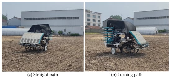
Figure 12.
Field test photo.
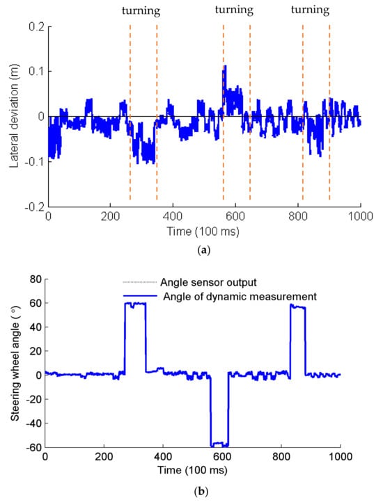
Figure 13.
Comparison of experiment results. (a) Variation of lateral deviation; (b) angle output.
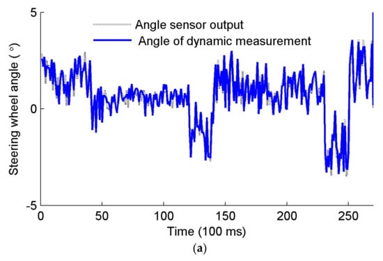
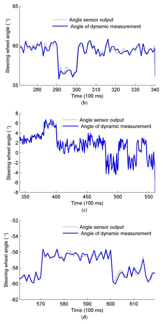
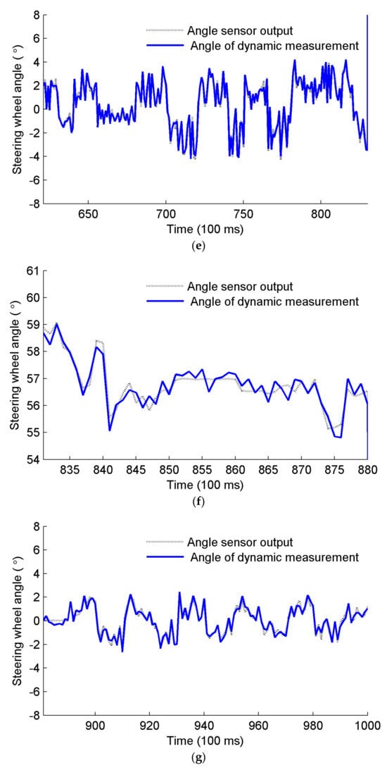
Figure 14.
Segmented amplification of Figure 13. (a) segmented amplification during 0–260 ms; (b) segmented amplification during 261–340 ms; (c) segmented amplification during 341–555 ms; (d) segmented amplification during 556–625 ms; (e) segmented amplification during 626–828 ms; (f) segmented amplification during 829–880 ms; (g) segmented amplification during 881–1000 ms.
Table 5 gives some data points of the straight path. All data points in Table 3 are obtained in a chronological sequence and cover the experiment time of the whole straight path.
Table 5.
Comparison of two kinds of angle measurement on a straight path (°).
Similarly, Table 6 shows the partial data of the turning path and all data points traversing the whole turning path.
Table 6.
Comparison of two kinds of angle measurement on turning path (°).
4.3. Discussion
It can be seen from Figure 14a that the lateral deviation is less than 3 cm on the straight path, which meets the practical precision requirements of agricultural operations. Although the maximum value of the lateral deviation reaches 15 cm on the turning path, there is no need to over-demand the tracking accuracy of the turn as long as the straight working path meets the accuracy requirements. The lateral deviations of the autopilot system are less than 2.5 cm and 9.0 cm in straight-line tracking and curved-path tracking, respectively [21]. Although the precision of the proposed dynamic measurement method of the front-wheel steering angle is slightly lower than that of the reference [21], the kinematic model of the vehicle does not need to be established in this study. Thus, the separate calibration for different vehicles is avoided since the proposed measurement method does not depend on the kinematic models of the vehicles.
Figure 14a shows that the steering angles from two different measurement modes are close and the maximum deviation is 0.26°. This signified that the zero position error can be effectively eliminated by the optimization method of zero position error. The cases in Figure 14c,e,g are almost identical to those of Figure 14a. This further suggested that the proposed measurement method is effective on straight paths. For the cases in Figure 14b,d,f that happened in the headland turning, the maximum deviation between the angle sensor output and angle of dynamic measurement is 0.49°, 0.64°, and 0.67°, respectively. The reason is perhaps that the parameter combination such as the step length j, the boundary of the adjustable range , and adjustment step size is not optimal. The optimal parameter combination will be addressed in future research.
It can be found (Table 5) that the absolute error is not more than 0.5°. The analysis of error data over the whole experiment process shows that the average absolute error is 0.057° and the standard deviation of error is 0.483°. The average error and the error variance in the straight-line path are 0.060° and 0.215°, respectively [18]. Table 6 shows that the absolute error is not more than 0.7°. The analysis of error data over the whole experiment process demonstrates that the average absolute error of the turning path is 0.686° and the standard deviation of error is 0.931°. The average error and the error variance in the straight-line path are 0.746°and 0.908°, respectively [18]. This comparison implies that the sensing accuracy of the steering angle is almost the same. However, the kinematic models of the vehicles and the error model of the gyroscope are unnecessary in this study.
In summary, the absolute angular sensor can be replaced by the steering angle measurement system developed in this study. This implies that the prominent problems such as complicated installation and debugging, spattered mud blocking the parallel four-bar mechanism, and separate calibration for installation of different vehicles are avoided. The optimization method of zero position error can effectively improve the accuracy of the steering angle. The contribution of this study is providing a dynamic measurement method for steering wheel angle which hardly relies on the complicated vehicle kinematics model and error equation of steering wheel angle. This provides novel solutions for low-chassis vehicles such as rice transplanters which can prevent water from entering the sensor and causing degradation of the sensor performance or sensor damage by installing the sensor at a higher position. Given that the attitude sensor can be installed at a higher position on the wheel, the sensor damage from mud blocking and sensor wire breaking is also avoided.
5. Conclusions
A non-contact dynamic measurement method for the steering wheel angle of autonomous wheeled vehicles is proposed by integrating vehicle attitude information and non-contact attitude sensor information. In practical operation, it is difficult to ensure an absolute parallel between the wheel and the body through manual adjustment, resulting in zero position error in the front steering wheel angle. However, it is found that zero position error affects the lateral deviation of target path tracking in a steady state by analyzing the impact of zero position error on path tracking performance. Subsequently, an optimization method for zero position error of the front steering wheel angle is presented to improve the sensing accuracy of the front-wheel angle. Finally, the field test and data analysis are conducted to test and validate the proposed approaches. Field experiments show that the non-contact dynamic measurement method of vehicle steering wheel angle proposed in this paper has the same accuracy as in the traditional method obtained by angle sensors and supporting mechanical structures. However, the reliability is greatly improved. The average absolute error of the straight path is 0.057° and the corresponding standard deviation of error is 0.483°. The average absolute error of the turning path is 0.686° and the standard deviation of error is 0.931°. Compared with the traditional measurement methods, the non-contact measurement method proposed in this paper has the advantages of simple installation, no need for complex mechanical mechanism design, low installation accuracy, and good waterproof performance, which provides technical support for improving the reliability and efficiency of unmanned agricultural machinery.
The shortcoming of the proposed measurement method for the steering wheel angle is that it can only be adopted for autonomous vehicles with autonomous navigation systems such as GPS or Beidou. Moreover, the influence of vehicle vibration on the stability and accuracy of the attitude sensor is not considered. The performance of the attitude sensor under different vibration sources such as the engine (at different speeds), vehicle chassis, and bumpy roads will be explored in future research.
Author Contributions
Conceptualization, J.L. and Z.W.; methodology, Z.S.; software, Z.W.; validation, J.L.; formal analysis, Z.S.; investigation, J.L.; resources, J.L.; data curation, Z.S.; writing—original draft preparation, Z.W.; writing—review and editing, M.L.; visualization, M.L.; supervision, J.L.; project administration, J.L. All authors have read and agreed to the published version of the manuscript.
Funding
This research was funded by the Key Research and Development Program of Zhenjiang city (NY2022008), the Key Research Development Program of Jiangsu Province (BE2018324), and a project funded by the Priority Academic Program Development of Jiangsu Higher Education Institutions (No. PAPD-2023-87).
Institutional Review Board Statement
Not applicable.
Informed Consent Statement
Not applicable.
Data Availability Statement
Dataset available on request from the authors.
Conflicts of Interest
The authors declare no conflicts of interest.
References
- Wang, A.C.; Zhang, W.; Wei, X.H. A review on weed detection using ground-based machine vision and image processing techniques. Comput. Electron. Agric. 2019, 158, 226–240. [Google Scholar] [CrossRef]
- Li, M.; Imou, K.; Wakabayashi, K.; Yokoyama, S. Review of research on agricultural vehicles autonomous guidance. Int. J. Biol. ENG 2009, 2, 1–16. [Google Scholar]
- Zhou, J.; He, Y.Q. Research progress on navigation path planning of agricultural machinery. Trans. Chin. Soc. Agric. Mach. 2021, 52, 1–14. (In Chinese) [Google Scholar]
- Huang, W.Y.; Ji, X.; Wang, A.Z.; Wang, Y.F.; Wei, X.H. Straight-line path tracking control of agricultural tractor-trailer based on fuzzy sliding mode control. Appl. Sci.-Base 2023, 13, 872. [Google Scholar] [CrossRef]
- Zhang, Z.G.; Huang, H.X.; Luo, X.W.; Zhang, G.C.; Zhang, W.Y.; Peng, M.D.; Liu, W.L. Steering control system for a tractor using electric steering wheel. Trans. Chin. Soc. Agric. Mach. 2024, 40, 48–57. [Google Scholar]
- Ji, X.; Wei, X.H.; Wang, A.Z.; Cui, B.B.; Song, Q. A novel composite adaptive terminal sliding mode controller for farm vehicles lateral path tracking control. Nonlinear Dyn. 2022, 10, 2415–2428. [Google Scholar] [CrossRef]
- Ma, Z.H.; Yin, C.; Du, X.Q.; Zhao, L.J.; Lin, L.P.; Zhang, G.F.; Wu, C.Y. Rice row tracking control of crawler tractor based on the satellite and visual integrated navigation. Comput. Electron. Agric. 2022, 197, 106935. [Google Scholar] [CrossRef]
- Lim, J.H.; Choi, K.H.; Cho, J.; Lee, H.K. Integration of GPS and monocular vision for land vehicle navigation in urban area. Int. J. Automot. Technol. 2017, 18, 345–356. [Google Scholar] [CrossRef]
- Cui, B.B.; Zhang, J.X.; Wei, X.H.; Cui, X.Y.; Sun, Z.Y.; Zhao, Y.; Liu, Y.F. Improved information fusion for agricultural machinery navigation based on context-constrained Kalman filter and dual-antenna RTK. Actuators 2024, 13, 160. [Google Scholar] [CrossRef]
- Xie, B.; Jin, Y.C.; Faheem, M.; Gao, W.J.; Liu, J.Z.; Jiang, H.K.; Cai, L.J.; Li, Y.X. Research progress of autonomous navigation technology for multi-agricultural scenes. Comput. Electron. Agric. 2023, 211, 107963. [Google Scholar] [CrossRef]
- Lan, Y.B.; Zhao, D.N.; Zhang, Y.F.; Zhu, J.K. Exploration and development prospect of eco-unmanned farm modes. Trans. Chin. Soc. Agric. Mach. 2021, 37, 312–327. [Google Scholar]
- Chen, T.T.; Xu, L.Z.; Ahn, H.S.; Lu, E.; Liu, Y.B.; Xu, R.J. Evaluation of headland turning types of adjacent parallel paths for combine harvesters. Biosyst. Eng. 2023, 233, 93–113. [Google Scholar] [CrossRef]
- Hu, S.P.; Shang, Y.H.; Liu, H. Comparative test between displacement and four-bar indirect measurement methods for tractor guide wheel angle. Trans. Chin. Soc. Agric. Mach. 2017, 33, 76–82. [Google Scholar]
- Miao, C.X.; Chu, H.X.; Gao, J.J.; Sun, Z.H.; Yi, R.R. Steering angle adaptive estimation system based on GNSS and MEMS gyro. Comput. Electron. Agric. 2018, 153, 196–201. [Google Scholar] [CrossRef]
- Yin, X.; Du, J.; Noguchi, N.; Yang, T.X.; Jin, C.Q. Development of autonomous navigation system for rice transplanter. Int. J. Agric. Biol. Eng. 2018, 11, 89–94. [Google Scholar] [CrossRef]
- Li, J.Y.; Shang, Z.J.; Li, R.F.; Cui, B.B. Adaptive sliding mode path tracking control of unmanned rice transplanter. Agriculture 2022, 12, 1225. [Google Scholar] [CrossRef]
- Li, J.Y.; Zhang, M.; Zhang, G.; Ge, D.Q.; Li, M.Q. Real-time monitoring system of seedling amount in seedling box based on machine vision. Agriculture 2023, 13, 371. [Google Scholar] [CrossRef]
- Miao, C.X.; Chu, H.X.; Sun, Z.H. Wheel turning angle measurement system based on double GNSS antennas and single Gyro. Trans. Chin. Soc. Agric. Mach. 2017, 48, 17–23. [Google Scholar]
- Xiao, M. A high-accuracy steering wheel angle sensor based on GMR. In Proceedings of the Sixth International Conference on Instrument & Measuremnet Computer Communication and Control, Harbin, China, 21–23 July 2016. [Google Scholar]
- Butt, M.A.; Riaz, F.; Khalid, S.; Abid, S.; Habib, M.A.; Shafique, S.; Han, K. Micro-electromechanical system based optimized steering angle estimation mechanism for customized self-driving vehicles. Meas. Control 2021, 54, 429–438. [Google Scholar] [CrossRef]
- Chen, Y.; He, Y. Development of agricultural machinery steering wheel angle measuring system based on GNSS attitude and motor encoder. Trans. Chin. Soc. Agric. Mach. 2021, 37, 10–17. [Google Scholar]
- Santana-Fernndez, J.; Gomez-Gil, J.; Del-Pozo-San-Cirilo, L. Design and implementation of a GPS guidance system for agricultural tractors using augmented technology. Sensors 2010, 10, 10435–10447. [Google Scholar] [CrossRef] [PubMed]
- Nagasaka, Y.; Umeda, N.; Kanetai, Y.; Taniwaki, K.; Sasaki, Y. Autonomous guidance for rice transplanting using global positioning and gyroscopes. Comput. Electron. Agric. 2004, 43, 223–234. [Google Scholar] [CrossRef]
- Lohan, S.K.; Narang, M.K.; Singh, M.; Singh, D.; Sidhu, H.S.; Singh, S.; Dixit, A.K.; Karkee, M. Design and development of remote-control system for two-wheel paddy transplanter. J. Field Robot. 2021, 39, 177–187. [Google Scholar] [CrossRef]
- Bayar, G.; Bergerman, M.; Koko, A.B.; Konukseven, E.I. Localization and control an autonomous orchard vehicle. Comput. Electron. Agric. 2015, 115, 118–128. [Google Scholar] [CrossRef]
- Yang, J.; Chang, T.N.; Hou, E. Lateral control for vehicle automatic steering with front sensor and GPS. In Proceedings of the International Conference on Control, Automation and Systems (ICCAS 2010), Gyeonggi-do, Republic of Korea, 27–30 October 2010; pp. 928–932. [Google Scholar]
- Groves, P.D. Navigation using inertial sensors. IEEE Aerosp. Electron. Syst. Mag. 2015, 2, 42–69. [Google Scholar] [CrossRef]
Disclaimer/Publisher’s Note: The statements, opinions and data contained in all publications are solely those of the individual author(s) and contributor(s) and not of MDPI and/or the editor(s). MDPI and/or the editor(s) disclaim responsibility for any injury to people or property resulting from any ideas, methods, instructions or products referred to in the content. |
© 2024 by the authors. Licensee MDPI, Basel, Switzerland. This article is an open access article distributed under the terms and conditions of the Creative Commons Attribution (CC BY) license (https://creativecommons.org/licenses/by/4.0/).