Abstract
To design and analyze a hook lock mechanism for a certain type of aircraft landing gear, numerical continuation and bifurcation theory are employed to study the performance of the lock mechanism in this paper. First, dynamic and static models of the hook lock mechanism are created separately, and by analyzing the locking and unlocking processes of the lock mechanism, the dynamic results are compared with the static numerical continuation results. According to the results, the static numerical continuation results agree excellently with the dynamic model results at the position of the stable equilibrium solution. Although the dynamic results can hardly explain the jump phenomenon of the lock mechanism at the moment of locking or unlocking, the bifurcation point of the static results suggests the occurrence of a stability change in the lock mechanism at the moment of jumping, thereby explaining the jumping mechanism of the lock mechanism. Therefore, the influences of the landing gear overload, lock spring parameters and attachment position on the performance of the lock mechanism are investigated. Furthermore, the critical installation position of the limit stop is defined, and the critical unlocking force of the lock mechanism is designed optimally based on the multi-island genetic algorithm.
1. Introduction
Landing gear retraction systems are safety devices that guarantee the retraction action and locking capability in the retracted state of landing gear after aircraft take off as well as the extension action and locking capability in the deployed state prior to landing [1]. According to a Federal Aviation Administration (FAA) investigation report [2] and Boeing’s Statistical Summary of Commercial Jet Airplane Accidents [3], a considerable portion of landing gear failures are caused by failures of the retraction mechanism, in which lock mechanism failures are prevalent. The main failure modes include the locking failure, unlocking failure, and automatic unlocking of landing gear. Thus, the rational design of landing gear lock mechanisms and the analysis of locking performance are critical to the safe and reliable operation of the landing gear retraction system [4].
Earlier methods of designing landing gear lock mechanisms were often based on empirical modification and experimental verification. Such design patterns were procedurally cumbersome, causing high repetition rates and long cycles of design as well as high costs of development [5]. With the advancement of digital mockup technology [6], multidisciplinary co-simulation has become the mainstream method of lock mechanism design [7]. Lei [8] proposed a multidisciplinary co-simulation-based method for analyzing a system with a hydromechatronically coupled landing gear lock mechanism. The method allowed preferential analysis of the fault mechanism and fast implementation of fault diagnosis. Tian [9] and Ji [10] created co-simulation models of landing gear retraction dynamics with a hook lock and a linkage lock separately based on the Siemens Virtual.Lab Motion (Siemens, Berlin, Germany) and Siemens Imagine.Lab AMESim (Siemens, Berlin, Germany) and explored the effects of lock mechanism motion on the dynamic properties of the retraction system. After modeling the double-lock bar mechanism of a certain unmanned aerial vehicle (UAV) in Adams, Oh [11] analyzed the intersection load and stress level of the lock bars.
However, virtual prototypes and digital simulation technology also have severe limitations regarding the design of complex mechanisms, which are reflected in the following two aspects. One aspect involves handling changes in the stability characteristics of mechanical systems. The majority of today’s landing gear lock mechanisms (regardless of whether they employ hook or linkage locks) [1] jump instantaneously from an unstable state to a stable locked state at the moment of locking. In such a state, the lock mechanism cannot be unlocked without the unlocking device. This is also the case for the unlocking process. Prior to the advent of bifurcation theory, it was impossible to explain the jump phenomenon of lock mechanisms by only simulative or experimental means. Accordingly, it was also difficult to analyze the conditions and influencing factors of the lock jump from the mechanism perspective, which greatly restricted the design level of lock mechanisms. In fact, the lock jump phenomenon can be well explained by bifurcation theory. The lock mechanism bifurcates in the critical unstable state to reach a stable locked state from an unstable unlocked state or to reach a stable unlocked state from an unstable locked state [12]. The other aspect involves handling the system of complex nonlinear mechanisms. To analyze the instability characteristics of lock mechanisms, virtual simulation technology needs to employ a dynamic perturbation method for acquisition of the characteristics. If a parameter influence analysis is required, substantial iterative computations are needed, which are heavily burdensome. Therefore, virtual simulation technology can hardly offer fast, effective support for the selection of various key parameters in the early phase of mechanism design. In contrast, a combination of numerical continuation and bifurcation analysis can derive the steady changes in a nonlinear system according to the changing control parameters in a fast and accurate manner [13]. The combined method can optimize the design process of complex mechanisms greatly and shorten their development time, which can be a powerful analytical tool for use in the early stage of aircraft research and development (R&D).
Bifurcation theory has been applied in the aviation field for many years, mainly around a number of nonlinear dynamic problems such as the ground stability of aircraft taxiing [14,15], the flight stability of aircrafts [16,17], and the performance of complex lock mechanisms [18]. Regarding existing research of landing gear lock mechanisms, Knowles [12] was the first to use the numerical continuation algorithm combined with bifurcation theory for studying the performance of a certain landing gear lock linkage mechanism. As shown by the study, saddle node bifurcation appeared in the equilibrium solution, which corresponded to the unstable jump point of the lock mechanism, as presented in the dynamics results obtained when the lock mechanism was near the locking phase. This, in turn, explained the locking mechanism of the landing gear. Later, Knowles also analyzed the performance bifurcation characteristics of different lock mechanisms by targeting an integrated nose landing gear (NLG) with a combined uplock/downlock mechanism [19,20], a spatial single-sidestay main landing gear (MLG) mechanism [21] and a dual-sidestay MLG mechanism [22] and explored the influences of the spring parameters on the lock mechanism performance. In a study conducted by Yin [23], the locking and unlocking mechanisms of linkage locks were investigated, and the critical unlocking force was optimized.
Existing studies focus only on analyzing the bifurcation characteristics of linkage lock mechanisms, while the performance of the hook locks examined in this paper has never been studied. Compared to linkage locks, hook locks are structurally more complicated, so it is more difficult to analyze relevant motion mechanisms. In this paper, a numerical continuation algorithm and bifurcation theory are employed to study the hook lock mechanism and to elucidate the locking principle of hook locks. Further, the influences of the landing gear weight and lock spring parameters on the performance of the lock mechanism are explored, and the minimum unlocking force of the lock mechanism is optimized, thereby establishing a novel bifurcation theory-based method for designing and analyzing hook locks for landing gear.
2. System Modeling
2.1. Research Object
The hook lock mechanism is used to achieve smooth locking of the landing gear in the up position after retraction into the aircraft cabin. In Figure 1, the schematics of a particular landing gear hook lock are presented. The lock mechanism is composed of linkage 1, linkage 2, lock hook 3, a lock bracket (including an unlocking actuator), a spring, etc. It operates on the following principle. In the locking process, the landing gear retracts slowly, driven by the retraction actuator, and when the lock is almost closed, the uplock roller on the gear strikes the lock hook by the action of retraction actuator. Through the impact force , a counterclockwise moment is formed to rotate the hook, which also drives the corresponding rotation of linkages 1 and 2 until they cross the centerline by the action of the spring to reach a stable locked state. At this point, the pressure inside the retraction actuator chamber is relieved. After the landing gear loses support from the retraction driving force, the uplock roller, which originally impacted the upper hook edge during locking, turns to hang on the lower hook edge due to the action of gravity on the landing gear. This ultimately completes the locking process of the landing gear upper lock. During the unlocking of the hook lock, the hook is subjected to a moment that is opposite to the direction of the locking moment since the entire landing gear hangs on it. Linkages 1 and 2 are opened by overcoming the spring force and moment of the lock with the unlocking driving force , so that the lock mechanism leaves the stable overcenter state, and the roller separates itself from the hook by the action of gravity on the landing gear to complete unlocking.
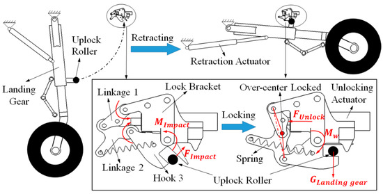
Figure 1.
Kinematic sketches of the hook lock mechanism.
2.2. Coordinate System
The o-xy coordinate system is established as shown in Figure 2. Origin O is the point at which the x-axis crossing hinge point A intersects the y-axis crossing hinge point D. The x-axis is defined along the horizontal leftward direction, and the y-axis is aligned with the global gravity vector. A, B, C, and D represent the hinge points between the three linkages. E denotes the action point of the unlocking force. F and G are the application points of the spring. represents the center of gravity of the ith component.
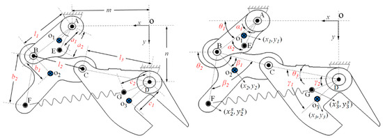
Figure 2.
Hook lock mechanism sketch.
2.3. Constraint Equations
As shown in Figure 2, there are three primary elements in the hook lock mechanism besides the lock bracket (linkage 1, linkage 2, and hook 3). Their locations can be described as (). This indicates that the mechanism has nine state variables, four revolute joints, and one degree of freedom (DOF). Therefore, eight constraint equations can be obtained, as presented in Equation (1).
The coordinate position of the spring point is obtained via Equation (2).
Here, (xi, yi) represents the center-of-gravity coordinates of the ith component; (,) represents the coordinate of the spring application point of the ith component; li is the length between two hinge points of the ith component; and m and n are the distances between the two hinge joints A and D of the lock bracket in the directions of x and y, respectively. a1, b1, and c1 denote the distances from the hinge points A, B, and D to the centers of gravity of the corresponding components. a2 is the distance from hinge joint A to action point E of the unlocking force ; b2 and c2 are the distances from hinge joints B and D to the application points of the spring, respectively; is the angle between the line which connects the two hinge points of the ith component and the x-axis (counterclockwise); and , , , , , and represent the angles of , , , , , and , respectively.
2.4. Dynamic Model
The dynamic model of the system is established based on the Lagrange equation. The basic form is expressed in Equation (3).
Here, L is the function that represents the difference between the kinetic energy and potential energy of the system; q is the generalized coordinate; and Q is the generalized external force.
The system has only one degree of freedom. is selected as the generalized coordinate, and the generalized external force is the unlocking force and moment of the uplock roller acting on the hook. It is noteworthy that and represent the locking and unlocking moments of uplock roller acting on the hook, respectively, which are denoted uniformly by M in the following sections for ease of presentation. Here, by taking the derivative of Equation (1) with respect to time, Equation (4) is obtained.
From Equation (4), the translational kinetic energy T1, the rotational kinetic energy T2, the gravitational potential energy V1, and the elastic potential energy V2 of the system can be obtained as follows.
Here, lu is the original length of the spring; k is the spring stiffness; mi is the mass of the ith component; and Ji is the rotational inertia of the ith component.
The dynamic equation of the system can be achieved by substituting Equation (9) into Equation (3).
2.5. Static Model
As shown in Figure 3, there are nine state variables in the lock mechanism. The static model in matrix form, as shown in Equation (10), can be derived from the force equilibrium equation and the moment equilibrium equation, and the nine state variables can be calculated from Equation (10).
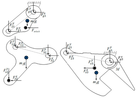
Figure 3.
The force analysis of the hook lock mechanism.
In addition, , , and
.
Here, is the unlocking force; is the force from the ith component to the jth component in the x direction; is the force from the ith component to the jth component in the y direction; is the spring force; is the force from the spring to the jth component in the x direction; is the force from the spring to the jth component in the y direction; is the force from the lock bracket to the jth component in the x direction; and is the force from the lock bracket to the jth component in the y direction.
3. Results of Dynamic and Static Analyses
3.1. Test Results
In order to examine the locking performance of hook lock, retracting and locking performance tests were carried out on the landing gear. Figure 4 illustrates the pressure results from the test, where the solid black curve represents the pressure in the rodless side chamber of retraction actuator, and the gray dashed line represents the unlocking pressure of hook lock. During retraction of the landing gear, hydraulic pressure is supplied to the rodless side chamber of retraction actuator. As the pressure rises, the landing gear is retracted slowly. When the pressure reaches the peak, it indicates that the lock roller hits the lock hook to complete the locking action. This peak value is precisely the critical impact force at which the hook lock can complete the locking action. By measuring and calculation based on the test pressure curve, the locking moment can be obtained that . During extension of the landing gear, the hook lock is unlocked initially to release the landing gear. At this point, the hydraulic system supplies pressure to the unlocking actuator, and the peak pressure site is precisely the critical driving force that enables unlocking of the hook lock. Calculation based on the measured pressure curve = 82.4 N.
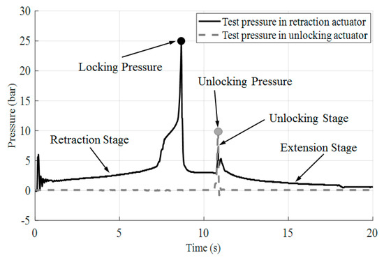
Figure 4.
Pressure curves from hook lock performance test.
3.2. Bifurcation Analysis Results
The equilibrium points of this mechanism system were determined using the numerical continuation algorithm in MATLAB (Mathworks, Natick, US). All the parameters are shown in Table 1 and the results are displayed in Figure 5.

Table 1.
Each parameter of hook lock.
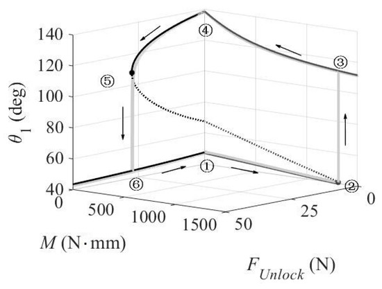
Figure 5.
Numerical continuation results of a typical locking and unlocking process.
In Figure 5, the black line represents the locking process, where , and the dark gray line represents the unlocking process, where M = 0, namely, . Here, the unlocking process is studied first without considering the influence of gravity on the landing gear temporarily. Detailed discussions will be given in the following section. Meanwhile, the solid line represents the stable equilibrium point, and the dotted line represents the unstable equilibrium point. If the system undergoes a small disturbance near a stable equilibrium point, it will converge to the stable point. Moreover, if the system suffers a small disturbance near an unstable equilibrium point, it will immediately jump to a stable equilibrium point.
Combined with the schedules of the hook lock mechanism in Figure 6, the locking and unlocking process can be inferred from the equilibrium solution curves. In Figure 5, position ① is the stable equilibrium point of the unlocked state. When the hook lock begins to lock, the upper lock moves from position ① to position ② as M slowly increases. Position ② is the bifurcation point of the locking process (black solid dot). As M continues to increase, the mechanism quickly jumps to position ③, where the lock enters the locked state. It is thus clear that the locking impact moment corresponding to position ② is precisely the critical impact force in the experimental test. The value is , with a 2.7% error compared with the test result, showing a high goodness of fit. Subsequently, as M decreases, the system moves to position ④ instead of returning by the original path. This suggests that position ④ is the stable equilibrium point of the locked state. The value of corresponding to this position is denoted by representing the locking ability of the hook lock mechanism. When the hook lock begins to unlock, the upper lock moves from position ④ to position ⑤ in the locked state as slowly increases. Position ⑤ is the bifurcation point of the unlocking process (black solid dot), at which the lock mechanism jumps rapidly to position ⑥, so that the hook lock reaches the locked state. Then, as decreases, the system moves back to position ①. Notably, each component of the lock will suffer interference in positions ① and ④. Actually, in the abrupt locking and unlocking processes, the lock will be limited by a stop block to prevent interference.
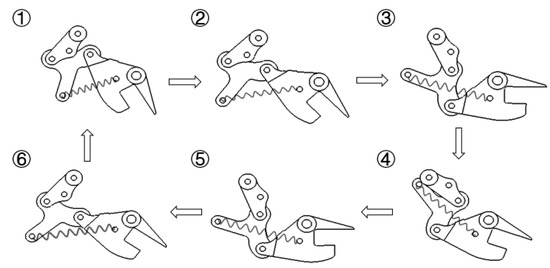
Figure 6.
Kinematic sketches of the hook lock mechanism.
3.3. Results of the Dynamic Model
In this section, the results of the dynamic model of the lock mechanism based on the Lagrange equation, which are shown as light gray lines in Figure 5, are compared with those of the static bifurcation analysis. The dynamic calculation process is described as follows. During locking, a locking moment M is applied to the hook. After stabilization of the mechanism, the stable angle of linkage 1 is obtained. Then, the magnitude of M is changed at specific steps to continue the computation, thereby obtaining the variation curve of with respect to M. Similarly, the variation curve of with respect to the unlocking force can be obtained during unlocking.
It can be seen from Figure 5 that the stable equilibrium points of the bifurcation analysis model agree well with the results of the dynamic calculations, however there are no evident unstable equilibrium points (dotted line) in the dynamic results. Notably, the results of the dynamic analysis show that linkage 1 jumps at a certain angle, but the dynamic model cannot explain the underlying principle of this phenomenon. According to the static bifurcation model, the lock bifurcates at the unstable equilibrium point, which causes the lock to jump from the unstable state to the stable state.
4. Unlocking Performance Analysis
Designers strive to make the unlocking force as small as possible to reduce the hydraulic pressure inside the unlocking actuator. The unlocking force is correlated closely with multiple parameters, including the landing gear weight, spring parameters, spring mounting position, etc. Therefore, the influences of the system parameters on the performance of the hook lock mechanism are analyzed during the unlocking process in this section.
4.1. The Influence of the Landing Gear Weight on the Unlocking Force
In the process of unlocking, the load applied to the hook by the uplock roller changes from the original impact force of the upper lock to the weight of the landing gear , which is greatly influential for the unlocking force . To consider the influence of the landing gear weight on the stability performance of the upper lock, the corresponding weight moment equation should be added:
where Mw is the locking moment corresponding to the weight of the landing gear; ξ is the distance from rotation point D of linkage 3 to the action line of the hitting force between the lock roller and hook; φ is the value of the angle at which the landing gear weight begins to take effect; and υ is a weight parameter related to the speed at which the weight of the landing gear acts on the lock.
The results are shown in Figure 7, into which the results without landing gear weight (light gray line) are integrated. Figure 7 clearly shows that w has a great impact on the stability performance of the lock mechanism. Influenced by the weight of the landing gear, the unlocking bifurcation curves of the lock mechanism undergo marked changes, and the unlocking force of upper lock also increases quickly with the increasing overload factor.
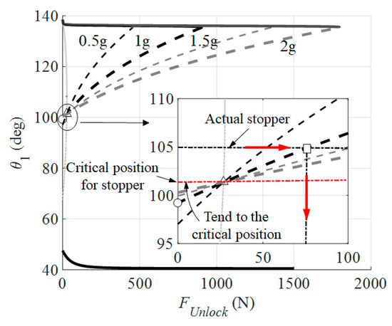
Figure 7.
The influence of the landing gear weight on the unlocking force.
As is known, the upper lock mechanism should never be unlocked automatically, no matter how large the aircraft maneuvering overload. The lock mechanism can be unlocked automatically in the following case. When , if the position of lock mechanism linkage 1 is less than a particular angle, the lock mechanism can jump automatically to the unlocked state from the locked state, even in the absence of an external driving force. Taking the computational result of a 1 g overload as an example (thick black line), the specific angle at which the lock mechanism can be unlocked automatically is = 99° (the angle corresponding to the circular dot in Figure 7) in this scenario. That is, for the 1 g overload case, the position of the limit stopper should be greater than 99°.
To study the variation trend of this specific angle, the limit stopper mounting position that satisfies all operating conditions was investigated. We calculated the unlocking curves under the following four conditions: 0.5 g, 1 g, 1.5 g, and 2 g. The results reveal that the specific unlocking angle tends to have a critical position of 101.3° with the increasing overload of the landing gear. Hence, it can be inferred that the specific angle will be infinitely close to 101.3° (the angle corresponding to a triangle in the figure) when the overload is infinite in theory. Accordingly, the lock mechanism can be in a completely locked state without being accidentally unlocked as long as its stopper position is greater than 101.3°, unless there are any external disturbances such as the maloperation of an unlocking actuator. When is between 99° and 101.3°, the landing gear is in a pseudolocked state, wherein the lock mechanism tends to be unlocked due to disturbances (e.g., overload on the landing gear due to supermaneuvering flight), despite the seemingly locked landing gear. Therefore, the pseudolocked state is dangerous.
For the upper lock mechanism of the actual aircraft landing gear discussed in this paper, the limit stopper is at (the angle corresponding to a square in the figure). The unlocking process is explained by taking the scenario of a 1 g overload as an example. When begins to increase from 0, the angle remains unchanged because of the action of the limit stopper (rightward arrow line in the partial view of Figure 7). As increases to an unstable equilibrium point (reaching the thick black dashed line), the system jumps immediately to a stable equilibrium point below (downward arrow line), and the upper lock is unlocked. Hence, the of the equilibrium point corresponding to is the upper lock unlocking force when the influence of the landing gear weight is taken into consideration. The numerical continuation result of this unlocking force is , with a 5% error compared with the test result, showing a high goodness of fit.
4.2. The Influence of the Spring Parameters on the Unlocking Force
The spring stiffness k and the original spring length lu directly affect the magnitude of the spring force. Different stiffnesses and original lengths result in diverse bifurcation points of this mechanism, thus affecting the magnitude of the unlocking force.
Figure 8 and Figure 9 show how the unlocking force varies with the stiffness k and the original length lu of the spring, respectively. The results indicate that the influences of k and lu on the unlocking force are linear. The unlocking force increases monotonically with increased k values and decreases monotonically with increased lu values, while is more sensitive to changes in k than to changes in lu.
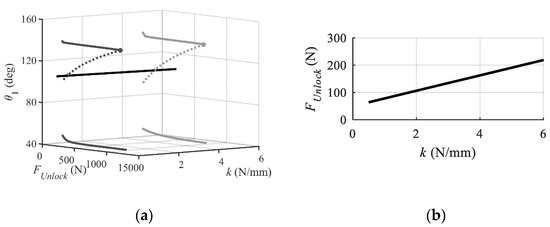
Figure 8.
The influence of k on : (a) Unlocking force varies with the stiffness k; (b) Projection of the trajectory in the -k plane.
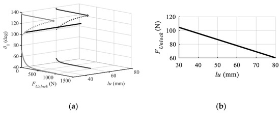
Figure 9.
The influence of lu on : (a) Unlocking force varies with the original length lu; (b) Projection of the trajectory in the -lu plane.
4.3. The Influence of the Spring Attachment Point on the Unlocking Force
The spring attachment point and angle affect the spring elongation and thus indirectly influence the spring force, which changes the position of the bifurcation point and the unlocking force of this mechanism.
Figure 10 and Figure 11 show how the unlocking force varies with changes in and , respectively. As shown by the results, the influence of on the unlocking force is linear, presenting a monotonically decreasing trend. With the increase in , becomes increasingly less sensitive to , but the change is insignificant. The influence of on the unlocking force is a monotonically increasing nonlinear function, so becomes ever more sensitive to with increasing values.
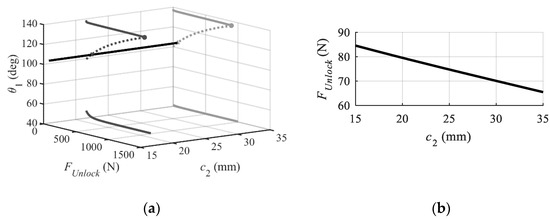
Figure 10.
The influence of on : (a) Unlocking force varies with the ; (b) Projection of the trajectory in the plane.
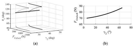
Figure 11.
The influence of on : (a) Unlocking force varies with the ; (b) Projection of the trajectory in the plane.
4.4. Parameter Sensitivity Analysis
On the basis of the foregoing analysis of single parameter influence on the unlocking force , this section carries out the sensitivity analysis concerning the multi-parameter influence on . This not only allows visualization of the importance of various parameters, but also provides an analytical basis for the subsequent optimization computation of the unlocking force. Figure 12 displays the sensitivity analysis results. As is clear, the spring stiffness k, the original spring length lu and the cross term k-lu have higher contributions to the unlocking force, while the spring mounting position parameters and contribute less to .
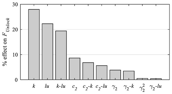
Figure 12.
Sensitivity analysis of parameters affecting the unlocking force.
5. Optimization Analysis of the Minimum Unlocking Force
This section describes the optimization analysis that was conducted to minimize the unlocking force based on the computer-aided engineering software ISIGHT (Dassault, France) combined with MATLAB. On the premise of ensuring an adequate locking ability of the hook lock mechanism (i.e., ensuring that satisfies the specified requirements), a multi-island genetic algorithm (MIGA) is applied to optimize considering the following variables including the spring stiffness k, the original spring length lu, the spring installation position and the spring angle .
The optimization process is illustrated in Figure 13. First, the bifurcation analysis model is established in MATLAB, and the optimization analysis model, ISIGHT, is also constructed. Each optimization iteration is completed in the locked area of the mechanism. Initially, a set of design variables is generated randomly according to the rules of MIGA, which is then passed to MATLAB to determine the motion trajectory and bifurcation position of the lock mechanism using a numerical continuation algorithm with the single parameter of the unlocking force. As a result, it obtains the angle characterizing the locking ability and the unlocking force enacted by the limit stopper. Afterwards, is checked to determine whether it conforms to the locking ability requirement, and is examined for its validity as a comparison value. If is an invalid comparison value, a new set of design variables is generated directly to enter the next iterative computation. In addition, if is a valid value, a comparison is made with the previous computational result to check for convergence. When the convergence requirement is met, the optimization computation ends. Otherwise, the next iterative computation is initiated likewise until the convergence requirement is satisfied.
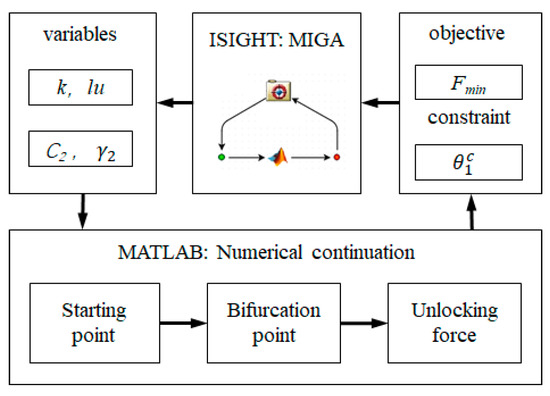
Figure 13.
The optimization process based on ISIGHT combined with MATLAB.
Here, the optimization problem can be expressed as follows based on the structural constraint and design requirements of the hook lock mechanism:
- Variables: ;;;.
- Constraint: .
- Objective: Min .
The optimization results are shown in Table 2. After optimization, the angle becomes slightly smaller than the initial value of 138.5°. Nevertheless, it conforms to the specified design requirement of 138°, which can thus guarantee the locking ability of the hook lock. In contrast, the unlocking force decreases from 78 N to 68.5 N, showing a reduction of 12.2%.
Table 2.
Optimization results for minimizing the unlocking force.
6. Conclusions
(1) In this paper, the combination of a numerical continuation algorithm and bifurcation theory was applied to the design and analysis of a hook lock mechanism for aircraft landing gear. The mechanism underlying the unstable jumping phenomenon of the lock mechanism was elucidated. Compared to conventional dynamical methods, the proposed combined method has unique advantages concerning the stability analysis of the mechanism, making it especially effective for use in the early stage of aircraft R&D.
(2) The hook lock mechanism is prone to pseudo-lock-up when the influence of the landing gear weight is taken into consideration. This paper analyzed in detail the conditions under which the lock mechanism can unlock automatically at various landing gear overloads. Additionally, the paper also derived the critical angle beyond which the hook lock can be in a completely locked state, thereby providing a design basis for the mounting position of the limit stopper for the lock mechanism.
(3) The influences of the lock spring parameters and mounting position on the performance of the lock mechanism were analyzed, and the unlocking force of the lock mechanism was optimized based on MIGA. The optimization results demonstrate that the unlocking force is reduced by 12.2% while ensuring the locking ability of the lock mechanism.
Author Contributions
Conceptualization, H.N. and X.W.; Methodology, Y.Y., X.W. and H.N.; Data curation, K.X. and Z.Z.; Software, K.X.; Validation, Y.Y.; Formal analysis, K.X.; Investigation, Y.Y. and K.X.; Resources, H.N. and X.W.; Writing—original draft preparation, K.X.; Writing—review and editing, Y.Y.; Supervision, H.N. and X.W.
Funding
This work was financially supported by the National Natural Science Foundation of China (51805249), the Natural Science Foundation of Jiangsu Province (BK20180436) and the Priority Academic Program Development of Jiangsu Higher Education Institutes.
Conflicts of Interest
The authors declare no conflict of interest.
References
- Aircraft Design Manual General Editorial Board. Aircraft Design Manual-Landing Gear System Design; Aviation Industry Press: Beijing, China, 2002. [Google Scholar]
- Reveley, M.S.; Briggs, J.L.; Evans, J.K.; Jones, S.M.; Kurtoglu, T.; Leone, K.M.; Sandifer, C.E. Causal Factors and Adverse Events of Aviation Accidents and Incidents Related to Integrated Vehicle Health Management; Aviation Safety Reporting System; NASA/TM-2011-216967; National Aeronautics and Space Administration: Washington, DC, USA, 2011. Available online: https://ntrs.nasa.gov (accessed on 4 December 2019).
- Boeing Commercial Airplanes. Statistical Summary of Commercial Jet Airplane Accidents Worldwide Operations 1959–2016, Aviation Safety, USA, Washington. 2017. Available online: http://www.boeing.com/news/techissues/pdf/statsum.pdf (accessed on 4 December 2019).
- Zhu, Z.; Feng, Y.; Lu, C.; Fei, C. Efficient Driving Plan and Validation of Aircraft NLG Emergency Extension System via Mixture of Reliability Models and Test Bench. Appl. Sci. 2019, 9, 3578. [Google Scholar] [CrossRef]
- Wang, H.; Yu, T.; Lei, M.; Song, B. Research on the architecture of simulative experiment system for mechanism motion reliability analysis. J. Mech. Eng. 2011, 47, 191–198. [Google Scholar] [CrossRef]
- Lu, Z.; Liu, J.; Dong, L.; Liang, X. Maintenance Process Simulation Based Maintainability Evaluation by Using Stochastic Colored Petri Net. Appl. Sci. 2019, 9, 3262. [Google Scholar] [CrossRef]
- Ameduri, S.; Concilio, A.; Favaloro, N.; Pellone, L. A Shape Memory Alloy Application for Compact Unmanned Aerial Vehicles. Aerospace 2016, 3, 16. [Google Scholar] [CrossRef]
- Lei, M.; Yu, T.; Song, B. Fault simulation of lock mechanism based on multi-disciplinary collaboration. Comput. Aided Eng. 2012, 21, 34–39. [Google Scholar]
- Tian, J.; Jia, Y. Modeling and Simulation of Large Civil Aircraft Landing Gear System. Mach. Des. Manuf. 2016, 5, 48–52. [Google Scholar]
- Ji, G.M.; Zhang, L.; Dong, M. Dynamic simulation on retraction /extension system of an aircraft. In Proceedings of the 2nd International Conference of Artificial Intelligenc, Management Science and Electronic Commerce, Zhengzhou, China, 8–10 August 2011; pp. 3939–3944. [Google Scholar]
- Oh, S.H. A study on development of dual locking linkage for landing gear for the application to UAV. Int. J. Control Autom. 2014, 7, 41–48. [Google Scholar] [CrossRef]
- Knowles, J.A.C.; Krauskopf, B.; Lowenberg, M.H. Numerical Continuation Applied to Landing Gear Mechanism Analysis. J. Aircr. 2011, 48, 1254–1262. [Google Scholar] [CrossRef][Green Version]
- Krauskopf, B.; Osinga, H.M.; Galán-Vioque, J. Numerical Continuation Methods for Dynamical Systems; Springer: Berlin, Germany, 2007. [Google Scholar]
- Howcroft, C.; Krauskopf, B.; Lowenberg, M.H.; Neild, S.A. Influence of Variable Side-Stay Geometry on the Shimmy Dynamics of an Aircraft Dual-Wheel Main Landing Gear. SIAM J. Appl. Dyn. Syst. 2013, 12, 1181–1209. [Google Scholar] [CrossRef]
- Rankin, J.; Coetzee, E.B.; Krauskopf, B.; Lowenberg, M.H. Bifurcation and Stability Analysis of Aircraft Turning on the Ground. J. Aircr. 2009, 32, 499–510. [Google Scholar] [CrossRef][Green Version]
- Amit, K.K.; Jatinder, S. Aircraft design using constrained bifurcation and continuation method. J. Aircr. 2014, 51, 1647–1652. [Google Scholar]
- Paranjape, A.A. Symmetric steady flapping flight of bird-scale aircraft, using bifurcation and continuation method. In Proceedings of the AIAA Atmospheric Flight Mechanics Conference, Kissimmee, FL, USA, 5–9 January 2015. [Google Scholar]
- Sharma, S.; Coetzee, E.B.; Lowenberg, M.H.; Neild, S.A.; Krauskopf, B. Numerical continuation and bifurcation analysis in aircraft design: An industrial perspective. Philos. Trans. R. Soc. A 2015, 373, 20140406. [Google Scholar] [CrossRef] [PubMed]
- Knowles, J.A.; Lowenberg, M.H.; Neild, S.A.; Krauskopf, B.A. bifurcation study to guide the design of a landing gear with a combined uplock/downlock mechanism. Proc. R. Soc. A Math. Phys. Eng. Sci. 2014, 470, 20140332. [Google Scholar] [CrossRef] [PubMed]
- Knowles, J.A.C. Bifurcation Study of a Dynamic Model of a Landing-Gear Mechanism. J. Aircr. 2016, 53, 1468–1477. [Google Scholar] [CrossRef]
- Knowles, J.A.C.; Krauskopf, B.; Lowenberg, M. Numerical continuation analysis of a three-dimensional aircraft main landing gear mechanism. Nonlinear Dyn. 2013, 71, 331–352. [Google Scholar] [CrossRef][Green Version]
- Knowles, J.A.; Krauskopf, B.; Lowenberg, M.H.; Neild, S.A.; Thota, P. Numerical Continuation Analysis of a Dual-Sidestay Main Landing Gear Mechanism. J. Aircr. 2014, 51, 129–143. [Google Scholar] [CrossRef][Green Version]
- Yin, Y.; Neild, S.A.; Jiang, J.Z.; Knowles, J.A.; Nie, H. Optimization of a Main Landing Gear Locking Mechanism Using Bifurcation Analysis. J. Aircr. 2017, 54, 2126–2139. [Google Scholar] [CrossRef]
© 2019 by the authors. Licensee MDPI, Basel, Switzerland. This article is an open access article distributed under the terms and conditions of the Creative Commons Attribution (CC BY) license (http://creativecommons.org/licenses/by/4.0/).