Featured Application
The presented active control system aims to suppress the swing vibrations of suspended structures, e.g., a crane ship hook and suspension bridge deck; bending vibrations of super tall structures and towers; three rotary motions of offshore platforms or ships; and any dynamic system with rotational or rotary vibration or motion components.
Abstract
In traditional structural disaster prevention design, the effects of various disasters on structures are usually considered separately, and the effects of multi-type hazards are rarely considered. The traditional Tuned Mass Damper (TMD) and Active Mass Damper/Driver (AMD) are ineffective for the control of swing vibration. The Tuned Rotary Inertia Damper (TRID) system has the problems of being ineffective under multi-type hazard excitation and exhibiting a limited robustness. The Active Rotary Inertia Driver (ARID) system is proposed to solve these problems and the robustness of such an active control system is investigated in this paper. Firstly, the equations of motion corresponding to the in-plane swing vibration of the suspended structure with the ARID/TRID system are established. The control algorithm for the ARID system is designed based on the Linear Quadratic Regulator (LQR) algorithm. Next, numerical analyses carried out using Simulink are presented. Then, numerical analyses and experimental investigations corresponding to five working conditions, i.e., free vibration, forced vibration, sweep excitation, earthquake excitation, and sea wave excitation, are introduced. Lastly, the numerical analyses and experimental results of the ARID system, and numerical results of the TRID system, are compared to demonstrate the effectiveness and robustness of the ARID control system. It can be concluded that the ARID system is effective and feasible in structural swing vibration control and it exhibits a better control robustness than the TRID system. Furthermore, the feasibility of applying the ARID control system to multi-type hazard excitations is validated.
1. Introduction
In traditional disaster prevention design, various disaster effects are usually considered separately. The overall demand for structures facing various disasters is almost neglected. Multiple hazards, such as earthquakes, wind, impacts, and explosions, impose enormous technical challenges to structures. In general, multi-type hazard structural prevention design mainly considers two typical forms: structures facing different hazards at the same time or in a time sequence, and structures facing one of the various disasters. In most cases, only the earthquake disaster is considered when structural preventions are designed [1,2].
On the other hand, the pendular motion of the suspended structure is a typical and common form of motion. It mainly includes three basic motion modes, according to the relationship between the lifting point and the moving direction of the structures: the swing motion mode, the sway motion mode, and the swing and sway coupling motion mode [3]. Based on many practical applications and studies, the observation result shows that traditional vibration control devices such as the tuned mass damper (TMD) [4,5,6,7,8,9,10,11], tuned liquid damper (TLD) [12,13], particle damper (PD) [14], pounding tuned mass damper (PTMD) [15,16,17], and frictional tuned mass damper [18,19], are reliable and efficient for civil engineering structures. Active Mass Dampers (AMD) [20,21,22,23,24,25,26,27] have been widely studied in civil engineering for their superior effectiveness and larger spectral bandwidth [28,29,30,31,32]. There are many kinds of active [33,34,35,36] and semi-active [37] control devices for structural vibration control. However, these traditional devices are almost ineffective in the swing motion mode vibration control of suspended structures. Some researchers have conducted studies on solving the problems of pendulum motion control [38,39]. They propose an adaptive output-based command shaping (AOCS) technique [40], innovative controllers, nonlinear control algorithms, and control schemes [41,42,43] for the vibrations of cranes, but the control technologies that reduce the vibrations rely on the movement of the hanging points. However, the hanging points of many suspended structures are fixed, such as those of ship cranes. Therefore, it is meaningful to design a new control device for the swing motion of suspended structures.
For the swing vibration control of suspended structures, a kind of control device called the Tuned Rotary Inertia Damper (TRID) system was proposed in previous research. In this system, mass with rotary inertia is attached to the suspended structure and the torsional spring element embedded with a damping mechanism is installed between the inertia mass and the structure. The effectiveness of the TRID system for swing vibration control was verified by theoretical analyses and experiments. However, the TRID system has some defects, such as the structure swing angle, which is too small to start the TRID system normally. The TRID miniaturization device has a severe time-lag effect. The TRID system also has a limited robustness, so it has a limited control effect.
In previous studies, the performance of control systems under common single conditions has been verified based on experiments. The influence of external loads on the structural performance is ignored due to all of the attention being placed on the system configuration, thus the performance of the control system cannot be thoroughly evaluated. For example, the TRID system exerts a good control effect under specific frequency sinusoidal excitation. However, the control effects under multiple frequency excitations, such as earthquake excitation and sea wave excitation, have not been systematically studied.
Based on the TRID system, the Active Rotary Inertia Driver (ARID) system was proposed. The mathematical model of the ARID system was derived [44]. The system performance under the multi-hazard condition is comprehensively studied by numerical analyses and shaking table experiments in this paper. Furthermore, the performance of the ARID system under multi-type hazards is studied by considering five different external loads. The ARID system is effective and feasible in structural swing vibration control and it has a better control robustness than the TRID system. The feasibility of the ARID system application in multi-type hazard vibration control is proved in the primary mechanism.
2. Mathematical Modeling
The TRID system proposed before mainly consists of a torsional spring element and rotary inertia. Compared with the TRID system, the ARID system consists of an active driver and a rotary inertia. The simplified analytical models of the suspended structure with the ARID/TRID system are developed in order to investigate the dynamic characteristics of the ARID system, which are shown in Figure 1. The model consists of two degrees of freedom used as generalized coordinators, which are the structural pendular angle and relative rotation angle of the rotary inertia with respect to the ground base . The suspended structure has the swing length l, suspended particle mass m, and damping coefficient c. The control system rotary inertia mass is ma and the rotary inertia is Ja. The acceleration at the suspended structure lifting point is ax0(t). The rotational stiffness coefficient of the ARID system is ka. The damping coefficient is ca. The output torque of the ARID system is Ma(t). The motion equations [44] of the structure with the ARID system model are deduced based on the Lagrangian difference method as
where , , , , and are the required parameters. r is the radius of the mass inertia, ξ is the structural damping ratio, and ξa is the ARID damping ratio. Generally, the damping force and torsion resistance of the ARID system are very small compared with the control forces, which can be neglected (ca and ka are 0) [44].
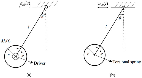
Figure 1.
The simplified analytical model of the suspended structure with the control system: (a) The structure with the Active Rotary Inertia Driver (ARID) system; (b) the structure with the Tuned Rotary Inertia Damper (TRID) system.
Equation (2) gives the damping force, torsion resistance, and output active control force of the ARID system. The motion equations of the system are linearized. Furthermore, the classical Linear Quadratic Regulator (LQR) algorithm is used in the system and the gain matrices A can be obtained [44]. The state vector is , and the active torque Ma(t) is given as
The rotational stiffness coefficient of the TRID system is kt. The damping coefficient is ct. Compared with the ARID system, the TRID system cannot output the active control torque. However, the TRID system is a kind of passive control system, and it needs frequency modulation according to the structure. The motion equations of the structure with the TRID system model are deduced based on the Lagrangian difference method as
where , , and ξt is the TRID damping ratio. For the TRID system, the key parameters and of the torsional spring have a great influence on the control effectiveness.
3. Sensitivity Analysis of the TRID/ARID System
3.1. Parameter Identification
There are two parameters reflecting the control effectiveness, defined as
where s is the root mean square, , is the angle mean, , and is the angle of i moment. θ1 is the swing angle without control and θ2 is the swing angle with control. is the root mean square without control and is the root mean square with the TRID or ARID control. The Peak reflects the control effect of the TRID or ARID system on the peak swing angle. The RMS reflects the control effect of the TRID or ARID system on swing angle dispersion.
3.2. Control Effectiveness under Different Excitation Frequencies
The numerical analysis models were established using Simulink, according to the motion equations of the TRID and ARID systems. A series of numerical analyses were carried out. The dynamic characteristics of the TRID and ARID systems were compared, according to the numerical analyses results.
Different sinusoidal excitation frequencies were applied to the suspended structures with the TRID and ARID systems. The numerical analyses parameters of the systems are shown in Table 1. is defined as the excitation frequency. The structural natural frequency can be obtained by . λ is defined as . Furthermore, the Peak and RMS of structures under different excitation frequencies were calculated to analyze the control effectiveness of the control systems.

Table 1.
Parameter configuration for the numerical analyses.
As shown in Figure 2, the control effectiveness of the TRID systems with different frequency modulation ratios were compared with the ARID system. The frequency modulation ratio γ is defined as γ = ωt/ωm, where ωt is the frequency of the TRID system. The frequency modulation ratio of TRID1, TRID2, …, TRID8 is 0.2, 0.4, …, 1.6, respectively. The structural parameters and the rotary inertia of the TRID and ARID systems are the same. It can be concluded from Figure 2 that the ARID system has a better control effectiveness than the TRID system under different excitation frequencies. Furthermore, the ARID system is less sensitive to the excitation frequency and has a better control robustness compared with the TRID system.
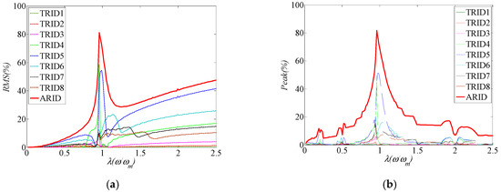
Figure 2.
Control effectiveness under different excitation frequencies: (a) Control effectiveness (Peak) of the ARID system and the TRID system with different frequency modulation ratios; (b) control effectiveness (RMS) of the ARID system and the TRID system with different frequency modulation ratios.
The control effectiveness of the TRID system with different frequency modulation ratios are also analyzed in this part. J is the rotary inertia of the TRID system. As shown in Figure 3, the rotary inertia gets bigger from J1 to J5. It can be seen that the TRID system has a better control effectiveness when the frequency modulation ratio γ is close to 1. The control effectiveness gets better as the rotary inertia gets bigger. Furthermore, the control effectiveness is sensitive to the frequency modulation ratio γ. When γ is changed from 1, the control effectiveness gets much worse. The control robustness of the TRID system is greatly affected by the frequency modulation ratio γ.
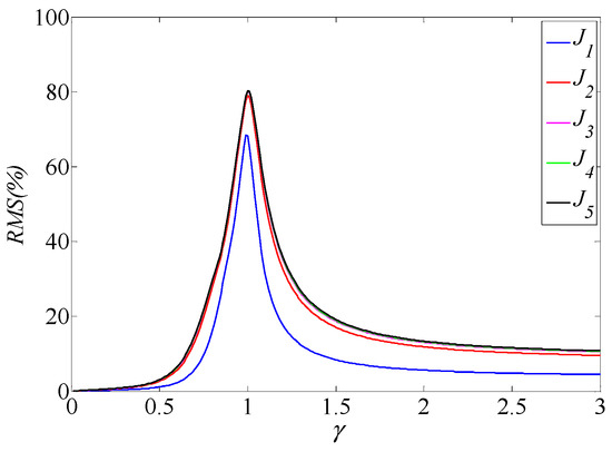
Figure 3.
Control effectiveness of the TRID system with different frequency modulation ratios.
4. Experimental Design
4.1. Experimental System Configuration
A shaking table experimental system is developed based on a simplified analytical model. The control system is designed as a closed-loop control system. It can adjust the output of the control torque in time, according to the real-time response of the structural swing angle [44]. The shaking table is used to apply excitations to the structure. The data acquisition device, the actuator, and the corresponding controller are also needed, according to the closed-loop control concept. The experimental system was designed as shown in Figure 4a,b. The structural response was the swing angle. The encoder was chosen as the data acquisition device to collect the swing angle. The suspended structure was installed with the encoder shaft. The ARID system analytical model is shown in Figure 4c. The motor with a round wheel was chosen as the actuator. The motor can drive the rotation of the rotary inertia as the response to apply control torque to the structure. The computer and amplifier were chosen as the digital controller. They can control the rotating motor mode.
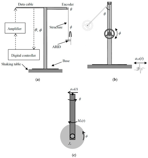
Figure 4.
Experimental system design: (a) Experimental system sketch; (b) suspended structure with the ARID system; (c) analytical model.
4.2. Experimental Setup
The experimental system was developed as shown in Figure 5. The shaking table was the Quanser single-axis shaking table II. The actuator was the Maxon DC motor with a planetary gearbox. The data acquisition devices were the US Digital encoder and Maxon encoder, employed to collect the swing angle and motor rotation angle. The sampling resolutions of the encoder were 0.0879° and 0.18°, respectively. The parameters of the experimental setup are shown in Table 2.
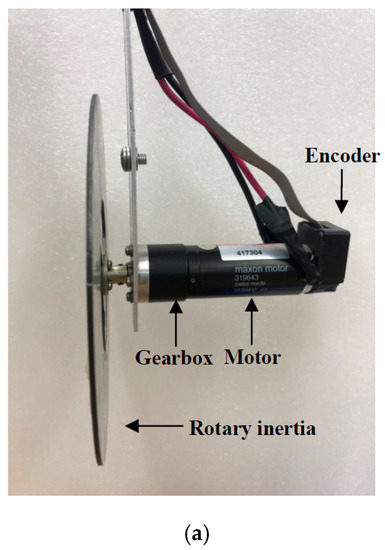
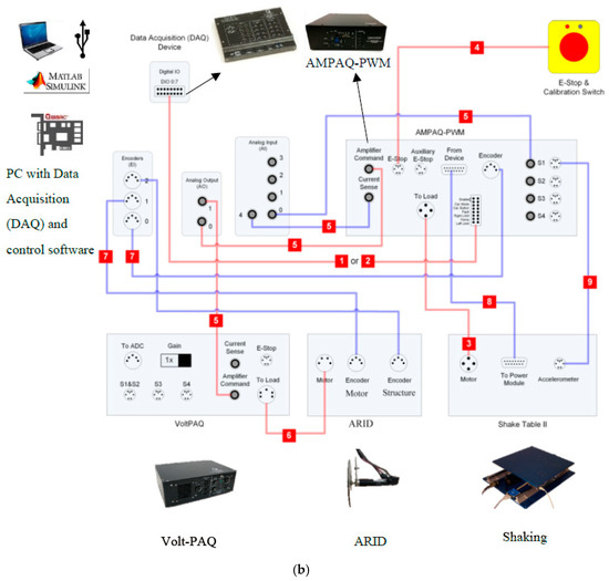
Figure 5.
Photo of the ARID experiment system: (a) Photo of the ARID actuator; (b) schematic of the experimental system.
Table 2.
Parameters of the experimental setup.
The natural structural frequency was close to 0.64 Hz, according to the equation . The rotary inertia was calculated by the software. The total mass of the ARID system was about 815 g. The suspended structural steel bracket was fixed on the shaking table and the bracket stiffness was regarded as infinity, and the excitation at the lifting point can be equivalently regarded as the shaking table excitation. The experimental control model was designed by Simulink. It was compiled and run by the Quanser software.
5. Control Effectiveness under Multi-Type Hazard Excitation
In this section, five kinds of working conditions for the TRID and ARID systems are presented to investigate the dynamic characteristics and control robustness. A series of numerical analyses and experiments were carried out. The numerical analysis models were established using Simulink. The experimental investigations of the ARID system were carried out using the shaking table and small-scale structures. The five kinds of working conditions were free vibration, forced vibration, sweep excitation, earthquake excitation, and sea wave excitation, respectively. They were designed to simulate the working conditions of the control systems under multi-type hazard loads and investigate the robustness of the control systems.
5.1. Free Vibration
In the first 15 s, the ARID system was not working. The resonance harmonic sinusoidal load was applied to the suspended structure. After 15 s, the structure started to swing freely and the ARID system started to work. The total sampling time was 40 s. Numerical analyses and experiments of the structure with the ARID system were carried out [44]. The numerical results of the structure with the ARID/TRID system are shown in Figure 6.
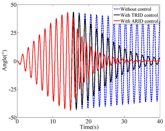
Figure 6.
Numerical results of the swing angle of the structure with the TRID or ARID system.
5.2. Forced Vibration
The total sampling time was 80 s. The sinusoidal load was applied to the suspended structure. The load amplitude was 20 mm and the frequency was 0.65 Hz (close to the natural structural frequency pf 0.64 Hz). Numerical analyses and experiments of the structure with the ARID system were carried out [44]. The numerical results of the structure with the ARID/TRID system are shown in Figure 7.
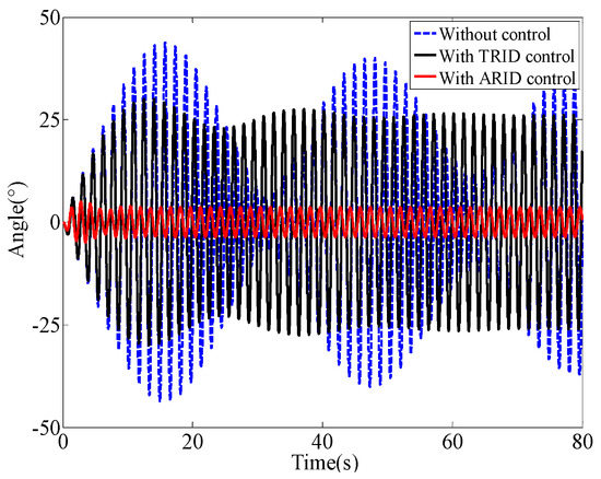
Figure 7.
Numerical results of the swing angle of the structure with the TRID or ARID system.
5.3. Sweep Excitation
In this condition, the total sample time was 110 s. The sweep load was applied to the suspended structure. The load amplitude was 10 mm, the initial frequency was 0.4 Hz, and the ending frequency was 1.5 Hz. The numerical results of the structure with the ARID/TRID system are shown in Figure 8. The numerical and experimental results of the structure with the ARID system are shown in Figure 9.
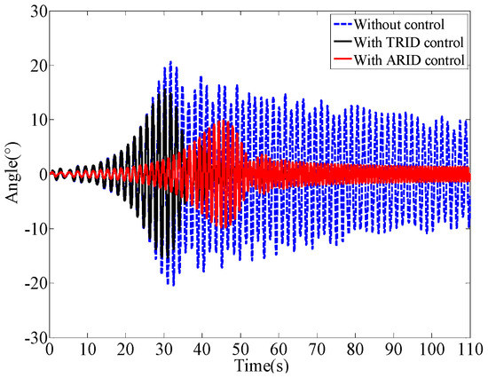
Figure 8.
Numerical results of the swing angle of the structure with the TRID or ARID system.
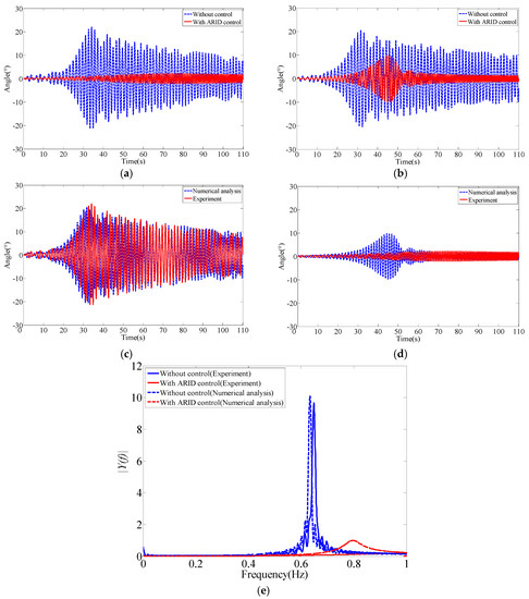
Figure 9.
The experimental and numerical results of the structure with the ARID system: (a) Results of experiments; (b) results of numerical analyses; (c) experimental and numerical results of the structure without control; (d) experimental and numerical results of the structure with ARID control; (e) amplitude–frequency curve.
5.4. Earthquake Excitation
In this condition, the total sample time was 25 s. The El Centro earthquake acceleration time history was processed and applied to the suspended structure. The numerical results of the structure with the ARID/TRID system are shown in Figure 10. The numerical and experimental results of the structure with the ARID system are shown in Figure 11.
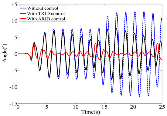
Figure 10.
Numerical results of the swing angle of the structure with the TRID or ARID system.
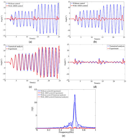
Figure 11.
The experimental and numerical results of the structure with the ARID system: (a) Results of experiments; (b) results of numerical analyses; (c) experimental and numerical results of the structure without control; (d) experimental and numerical results of the structure with ARID control; (e) amplitude–frequency curve.
5.5. Sea Wave Excitation
In this condition, the total sample time was 80 s. The white Gaussian noise was used as the sea wave acceleration [45,46] in this study. The acceleration time history was processed and applied to the suspended structure. The numerical results of the structure with the ARID/TRID system are shown in Figure 12. The numerical and experimental results of the structure with the ARID system are shown in Figure 13.
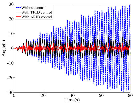
Figure 12.
Numerical results of the swing angle of the structure with the TRID or ARID system.
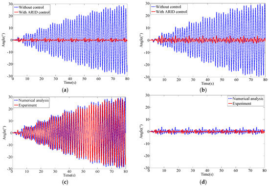
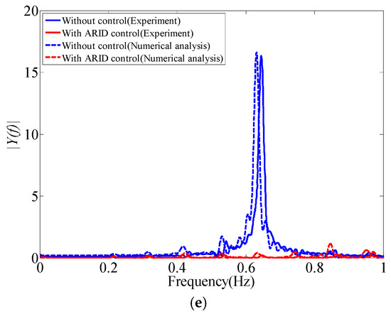
Figure 13.
The experimental and numerical results of the structure with the ARID system: (a) Results of experiments; (b) results of numerical analyses; (c) experimental and numerical results of the structure without control; (d) experimental and numerical results of the structure with ARID control; (e) amplitude–frequency curve.
5.6. Control Effectiveness Analysis
According to the numerical results of the structure with the TRID/ARID system, the control effectiveness is shown in Table 3. As shown in the swing angle time history, the structures with the ARID system have a smaller peak angle and a more stable response. It can also be seen in Table 3 that the control effectiveness of the ARID system is better in all cases. The ARID system shows a better robustness than the TRID system.
Table 3.
Control effectiveness comparison of the ARID system with the TRID system.
The control effectiveness analysis results of the five conditions [44] are shown in Table 4. As can be seen from the experimental and numerical results, it can be concluded that there is a very good agreement between the experimental and numerical results. The ARID system delivers a better control performance.
Table 4.
Control effectiveness comparison of the ARID system.
In the free vibration condition, the swing angle decreases very quickly. The swing angle response of the structures is totally controlled. The control effectiveness is apparent. In the forced vibration condition, the ARID system controls the swing angle within a small range and remains stable. The ARID system can absorb energy to reduce the influences of excitations on the structures. In the sweep excitation condition, the swing angle is also controlled within a small range. Furthermore, the swing angle exhibits a slight change as the excitation frequency changes. The structural response is stable. The ARID system can deliver a superior control performance in the whole frequency range. In the earthquake and sea wave excitation conditions, the swing angle is also controlled within a small range and the structural response is stable. When the excitation frequency changes rapidly, the swing angle may change rapidly, but the change is tiny compared with that of the structure without control. The ARID system acts as a filter and consumes excitation energy to reduce the structural response.
The control performance of the ARID system is excellent. It can significantly reduce the maximum swing angle of the suspended structure. The experimental results show that it can reduce more than 90% of the swing angle response in most working conditions. Furthermore, the swing angle can be controlled within a very small range and it can satisfy most of the structural stability demand. It can be concluded that the ARID system has a better robustness.
6. Conclusions
The robustness of the innovative active control system for swing vibration control, namely the Active Rotary Inertia Driver (ARID) system, has been investigated in this study. In order to further verify the characteristics of the ARID system, numerical analyses and experimental investigations of five working conditions (free vibration, forced vibration, sweep excitation, earthquake excitation, and sea wave excitation) were carried out. The numerical analyses and experimental results of the ARID system, and numerical results of the TRID system, were compared to demonstrate the effectiveness and robustness of the proposed ARID system. According to experimental and numerical results, the following conclusions can be drawn:
1. The ARID system is effective and feasible in structural swing vibration control and it exhibits a better control robustness than the TRID system;
2. The feasibility of the ARID system for multi-type hazard excitation-induced structural vibration control has been successfully demonstrated;
3. The closed-loop active control of the ARID system is effective. The ARID system is less sensitive to different external excitations and can deliver a superior control performance.
Author Contributions
C.Z. initiated the problem, proposed the idea, defined the research essentials, conceived the method, and revised the paper. H.W. carried out the theoretical research, parametric study, and experiments and prepared the draft.
Funding
The research is financially supported by the Ministry of Science and Technology of China (Grant No. 2017YFC0703603), the National Natural Science Foundation of China (Grant No. 51678322), the Taishan Scholar Priority Discipline Talent Group program funded by Shandong Province, and the first-class discipline project funded by the Education Department of Shandong Province.
Conflicts of Interest
The authors declare no conflicts of interest.
References
- Koks, E.E.; Rozenberg, J.; Zorn, C.; Tariverdi, M.; Vousdoukas, M.; Fraser, S.A.; Hall, J.W.; Hallegatte, S. A global multi-hazard risk analysis of road and railway infrastructure assets. Nat. Commun. 2019, 10, 2677. [Google Scholar] [CrossRef] [PubMed]
- Lin, K.; Lu, X.; Li, Y.; Guan, H. Experimental study of a novel multi-hazard resistant prefabricated concrete frame structure. Soil Dyn. Earthq. Eng. 2019, 119, 390–407. [Google Scholar] [CrossRef]
- Zhang, C.; Li, L.; Ou, J. Swinging motion control of suspended structures: Principles and applications. Struct. Control Health 2010, 17, 549–562. [Google Scholar] [CrossRef]
- Chen, S.R.; Cai, C.S. Coupled vibration control with tuned mass damper for long-span bridges. J. Sound Vib. 2004, 278, 449–459. [Google Scholar] [CrossRef]
- Wang, W.; Dalton, D.; Hua, X.; Wang, X.; Chen, Z.; Song, G. Experimental Study on Vibration Control of a Submerged Pipeline Model by Eddy Current Tuned Mass Damper. Appl. Sci. 2017, 7, 987. [Google Scholar] [CrossRef]
- Song, G.; Cai, S.; Li, H.N. Energy Dissipation and Vibration Control: Modeling, Algorithm, and Devices. Appl. Sci. 2017, 7, 801. [Google Scholar] [CrossRef]
- Shi, W.; Wang, L.; Lu, Z. Study on self-adjustable tuned mass damper with variable mass. Struct. Control Health 2018, 25, e2114. [Google Scholar] [CrossRef]
- Zuo, H.; Bi, K.; Hao, H. Using multiple tuned mass dampers to control offshore wind turbine vibrations under multiple hazards. Eng. Struct. 2017, 141, 303–315. [Google Scholar] [CrossRef]
- Matta, E. A novel bidirectional pendulum tuned mass damper using variable homogeneous friction to achieve amplitude-independent control. Earthq. Eng. Struct. Dyn. 2019, 48, 653–667. [Google Scholar] [CrossRef]
- Wang, L.; Shi, W.; Li, X.; Zhang, Q.; Zhou, Y. An adaptive-passive retuning device for a pendulum tuned mass damper considering mass uncertainty and optimum frequency. Struct. Control Health 2019, 26, e2377. [Google Scholar] [CrossRef]
- Ferreira, F.; Moutinho, C.; Cunha, Á.; Caetano, E. Proposal of optimum tuning of semiactive TMDs used to reduce harmonic vibrations based on phase control strategy. Struct. Control Health 2018, 25, e2131. [Google Scholar] [CrossRef]
- Banerji, P.; Murudi, M.; Shah, A.H.; Popplewell, N. Tuned liquid dampers for controlling earthquake response of structures. Earthq. Eng. Struct. Dyn. 2015, 29, 587–602. [Google Scholar] [CrossRef]
- Shum, K.M.; Xu, Y.L. Multiple tuned liquid column dampers for reducing coupled lateral and torsional vibration of structures. Eng. Struct. 2004, 26, 745–758. [Google Scholar] [CrossRef]
- Papalou, A.; Strepelias, E. Effectiveness of particle dampers in reducing monuments’ response under dynamic loads. Mech. Com. Mater. Struct. 2016, 23, 128–135. [Google Scholar] [CrossRef]
- Zhang, P.; Li, L.; Patil, D.; Singla, M.; Li, H.; Mo, Y.L.; Song, G. Parametric study of pounding tuned mass damper for subsea jumpers. Smart Mater. Struct. 2016, 25, 015028. [Google Scholar] [CrossRef]
- Jiang, J.; Zhang, P.; Patil, D.; Li, H.; Song, G. Experimental studies on the effectiveness and robustness of a pounding tuned mass damper for vibration suppression of a submerged cylindrical pipe. Struct. Control Health 2017, 24, e2027. [Google Scholar] [CrossRef]
- Tan, J.; Jiang, J.; Liu, M.; Feng, Q.; Zhang, P.; Ho, S.C.M. Implementation of Shape Memory Alloy Sponge as Energy Dissipating Material on Pounding Tuned Mass Damper: An Experimental Investigation. Appl. Sci. 2019, 9, 1079. [Google Scholar] [CrossRef]
- Jiang, J.; Ho, S.C.M.; Markle, N.J.; Wang, N.; Song, G. Design and control performance of a frictional tuned mass damper with bearing-shaft assemblies. J. Vib. Control 2019, 25, 1812–1822. [Google Scholar] [CrossRef]
- Pisal, A.Y.; Jangid, R.S. Vibration control of bridge subjected to multi-axle vehicle using multiple tuned mass friction dampers. Int. J. Adv. Struct. Eng. 2016, 8, 213–227. [Google Scholar] [CrossRef]
- Xu, H.; Zhang, C.; Li, H.; Tan, P.; Ou, J.; Zhou, F. Active mass driver control system for suppressing wind induced vibration of the Canton Tower structure. Smart Struct. Syst. 2014, 13, 281–303. [Google Scholar] [CrossRef]
- Francisco, P.; Josep, R.; Josep, M.; Hamid, R. Integrated Design of Hybrid Interstory-Interbuilding Multi-Actuation Schemes for Vibration Control of Adjacent Buildings under Seismic Excitations. Appl. Sci. 2017, 7, 323. [Google Scholar]
- Elisabet, S.; Andrés, R.; Antolino, G.; Amadeo, B.C. Entropy Analysis for Damage Quantification of Hysteretic Dampers Used as Seismic Protection of Buildings. Appl. Sci. 2017, 6, 628. [Google Scholar]
- Zhang, C.; Ou, J.; Zhang, J. Parameter Optimization and Analysis of Vehicle Suspension System Controlled by Magnetorheological Fluid Dampers. Struct. Control Health 2006, 13, 885–896. [Google Scholar]
- Preumont, A. Vibration Control of Active Structures: An Introduction; Springer: Berlin/Heidelberg, Germany, 2018; Volume 246. [Google Scholar]
- Li, H.; Song, G.; Kim, J.T.; Li, G. Smart Control Algorithms and Technology in Civil Infrastructures. Math. Probl. Eng. 2014, 2014, 1–2. [Google Scholar] [CrossRef]
- Fitzgerald, B.; Sarkar, S.; Staino, A. Improved reliability of wind turbine towers with active tuned mass dampers (ATMDs). J. Sound Vib. 2018, 419, 103–122. [Google Scholar] [CrossRef]
- Zhang, C. Control Force Characteristics of Different Control Strategies for the Wind-excited 76-story Benchmark Building Structure. Adv. Struct. Eng. 2014, 17, 543–559. [Google Scholar] [CrossRef]
- Venanzi, I.; Ierimonti, L.; Ubertini, F. Effects of control-structure interaction in active mass driver systems with electric torsional servomotor for seismic applications. Bull. Earthq. Eng. 2016, 15, 1543–1557. [Google Scholar] [CrossRef]
- Zhang, C.; Ou, J. Modeling and dynamical performance of the electromagnetic mass driver system for structural vibration control. Eng. Struct. 2015, 82, 93–103. [Google Scholar] [CrossRef]
- Zhang, C.; Ou, J. Control Structure Interaction of Electromagnetic Mass Damper System for Structural Vibration Control. J. Eng. Mech. ASCE 2008, 134, 428–437. [Google Scholar] [CrossRef]
- May, B.S.; Beck, J.L. Probabilistic control for the Active Mass Driver benchmark structural model. Earthq. Eng. Struct. Dyn. 2015, 27, 1331–1346. [Google Scholar] [CrossRef]
- Xu, H.; Zhang, C.; Li, H.; Ou, J. Real-time hybrid simulation approach for performance validation of structural active control systems: A linear motor actuator based active mass driver case study. Struct. Control Health 2014, 21, 574–589. [Google Scholar] [CrossRef]
- Camachogómez, C.; Wang, X.; Pereira, E.; Díaz, I.M.; Salcedo-Sanz, S. Active vibration control design using the Coral Reefs Optimization with Substrate Layer algorithm. Eng. Struct. 2018, 157, 14–26. [Google Scholar] [CrossRef]
- Ho, C.; Zhu, Y.; Lang, Z.Q.; Billings, S.A.; Kohiyama, M.; Wakayama, S. Nonlinear damping based semi-active building isolation system. J. Sound Vib. 2018, 424, 302–317. [Google Scholar] [CrossRef]
- Chey, M.H.; Chase, J.G.; Mander, J.B.; Carr, A.J. Semi-active tuned mass damper building systems, Design. Earthq. Eng. Struct. Dyn. 2010, 39, 119–139. [Google Scholar] [CrossRef]
- Behrooz, M.; Wang, X.; Gordaninejad, F. Modeling of a new semi-active/passive magneto rheological elastomer isolator. Smart Mater. Struct. 2014, 23, 045013. [Google Scholar] [CrossRef][Green Version]
- Fu, W.; Zhang, C.; Li, M.; Duan, C. Experimental Investigation on Semi-Active Control of Base Isolation System Using Magnetorheological Dampers for Concrete Frame Structure. Appl. Sci. 2019, 9, 3866. [Google Scholar] [CrossRef]
- Pappalardo, C.; Guida, D. Use of the Adjoint Method for Controlling the Mechanical Vibrations of Nonlinear Systems. Mach 2018, 6, 19. [Google Scholar] [CrossRef]
- Bertolazzi, E.; Biral, F.; Da Lio, M. Symbolic–numeric indirect method for solving optimal control problems for large multibody systems. Multibody Syst. Dyn. 2005, 13, 233–252. [Google Scholar] [CrossRef]
- Abdullahi, A.M.; Mohamed, Z.; Selamat, H.; Pota, H.R.; Abidin, M.S.Z.; Ismail, F.S.; Haruna, A. Adaptive output-based command shaping for sway control of a 3D overhead crane with payload hoisting and wind disturbance. Mech. Syst. Signal Process. 2018, 98, 157–172. [Google Scholar] [CrossRef]
- Mori, Y.; Tagawa, Y. Vibration controller for overhead cranes considering limited horizontal acceleration. Control Eng. Pract. 2018, 81, 256–263. [Google Scholar] [CrossRef]
- Mukhtar, F.H.; Hwa, J.Y.; Choudhury, I.A.; Isa, A.I.; Zimit, A.Y.; Kumbasar, T. Current development on using Rotary Inverted Pendulum as a benchmark for testing linear and nonlinear control algorithms. Mech. Syst. Signal Process. 2019, 116, 347–369. [Google Scholar]
- Maghsoudi, M.J.; Mohamed, Z.; Husain, A.R.; Tokhi, M.O. An optimal performance control scheme for a 3D crane. Mech. Syst. Signal Process. 2016, 66–67, 756–768. [Google Scholar] [CrossRef]
- Zhang, C.; Wang, H. Swing Vibration Control of Suspended Structure Using Active Rotary Inertia Driver System: Parametric Analysis and Experimental Verification. Appl. Sci. 2019, 9, 3144. [Google Scholar] [CrossRef]
- He, X.; Li, H. Suppression of random wave-induced vibrations in offshore platform by tuned liquid column damper. J. Vib. Eng. 2008, 21, 71–78. [Google Scholar]
- Chatterjee, T.; Chakraborty, S. Vibration mitigation of structures subjected to random wave forces by liquid column dampers. Ocean Eng. 2014, 87, 151–161. [Google Scholar] [CrossRef]
© 2019 by the authors. Licensee MDPI, Basel, Switzerland. This article is an open access article distributed under the terms and conditions of the Creative Commons Attribution (CC BY) license (http://creativecommons.org/licenses/by/4.0/).