Article

Natural Convection of Dusty Hybrid Nanofluids in an Enclosure Including Two Oriented Heated Fins

by
Zehba A.S. Raizah
Department of Mathematics, Faculty of Science, King Khalid University, Abha 61421, Saudi Arabia
Appl. Sci. 2019, 9(13), 2673; https://doi.org/10.3390/app9132673
Submission received: 17 April 2019 / Revised: 27 June 2019 / Accepted: 27 June 2019 / Published: 30 June 2019
(This article belongs to the Special Issue Nanofluids and Their Applications 2019)

Abstract

:
In the current work, the natural convection of dusty hybrid nanofluids in an enclosure including two inclined heated fins has been studied via mathematical simulation. The inclined heated fins are arranged near to the enclosure center with variations on their orientations and lengths. The present simulation is represented by two systems of equations for the hybrid nanofluids that are dusty. The pressure distributions for the dusty phase and hybrid nanofluids phase are evaluated using a SIMPLE algorithm based on the finite volume method. The numerical results are examined using contours of the streamlines, isotherms for the hybrid nanofluids and velocity components for the dusty phase. In addition, the graphical illustrations for profiles of the local and average Nusselt numbers are presented. The main results reveal that an increase in the mixture densities ratio and dusty parameter reduces the rate of the heat transfer. Both the local and average Nusselt numbers are supported as the fins lengths increase regardless of the fins’ rotation. In addition, the nanoparticles volume fraction enhances the thermal boundary layer near the top wall.

1. Introduction

The studies of the flow of fluids with suspended dust particles have been attracted the attention of numerous researchers due to their practical applications in various problems of atmospheric, engineering and physiological fields [1]. Farbar and Morley [2] were the first researchers who analyzed the gas-particulate suspension on experimental grounds. Singleton [3] studied the boundary layer analysis for the dusty fluid. Gireesha et al. [4] had been considered the geometry of the laminar flow of an unsteady viscous fluid with a uniform distribution of dust particles through a rectangular channel under the influence of the pulsatile pressure gradient. Later, numerous authors [5,6,7,8,9,10] investigated the dynamics of the two-phase flow under different physical circumstances.
The method of the suspending dissimilar nanoparticles in either mixture or composite form was known as the hybrid nanofluid. Hybrid nanofluids are a new type of enhanced working fluids, engineered with enhanced thermophysical properties. The hybrid nanofluids profit from the thermo-physical properties of more than one type of nanoparticles. In recent years, many authors have used hybrid nanofluids [11,12,13]. Mehryan et al. [14] studied the free convective heat transfer of the Al2O3-Cu water hybrid nanofluid in a cavity filled with a porous medium. They considered two types of important porous media, glass ball and aluminum metal foam, for the porous matrix. Hussain et al. [15] performed computational analyses in a horizontal channel with an open cavity filled with a hybrid nanofluid of Al2O3-Cu/water. They studied the effect of Richardson number, nanoparticle volume fraction and Hartmann number on the streamlines, isotherms, average Nusselt number and entropy generation. Mansour et al. [16] investigated the effects of magnetic field on the natural convection flow of hybrid, Al2O3-water, or Cu-water nanofluids, in a square cavity with two pairs of heat source-sink. Ashorynejad and Shahriari [17] adopted the lattice Boltzmann method to study the natural convection heat transfer of Al2O3-Cu/water hybrid nanofluid within an open wavy cavity subjected to a uniform magnetic field. The magnetohydrodynamic (MHD) flow and heat transfer of non-Newtonian micropolar dusty fluid suspended with Cu-Al2O3 hybrid nanoparticles past a stretching sheet were investigated by Ghadikolaei et al. [18]. Sheikholeslami et al. [12] presented the analysis of magnetizable hybrid nanofluid of multi-walled carbon nanotubes (MWCNT)-Fe3O4/H2O inside a circular cavity with two circular heaters. Chamkha et al. [19] adopted the Control volume finite element method (CVFEM) method to study the effects of thermal radiation and shape factor of nanoparticles’ impacts on magnetohydrodynamic nanofluid natural convection in a cavity.
On the other hand, Mozaffari et al. [20] studied the effects of asphaltene aggregation on rheological properties of diluted athabasca bitumen. Darjani et al. [21] derived the equation of state of lattice gases based on the random sequential adsorption simulations. Mozaffari et al. [22,23] introduced capillary driven flow to probe liquids’ rheology in nanofluidic systems and adopted an engine model consisting of a spherical Janus colloid coated with a symmetrical catalyst cap, which converts fuel into a product solute. Hosseini et al. [24] studied numerically the effects of poly disperse particle size, particle mass and flow velocity on the deposition ratio in fin channels.
To enhance the heat transfer rate within the cavities, some of the researchers added fins to the cavity walls. Liu et al. [25] studied experimentally the natural convection flow adjacent to a finned sidewall of a differentially heated cavity using the shadowgraph technique. Varol and Ozgen [26] studied the natural convection in a square cavity including an inclined fin on the wall. Kolsi et al. [27] analyzed the natural convection and entropy generation in a three-dimensional cavity with an inclined fin. They observed that the inclination angle significantly affect the heat transfer and the fluid flow. Elatar et al. [28] studied the laminar natural convection in a square cavity attached with a horizontal fin. They investigated the effect of different aspects of the fins such as length, thickness, conductivity ratio, and position. Ma and Xu [29] performed a numerical study on the unsteady natural convection of a differentially heated finned cavity. It was shown that the heat transfer is a function of the Rayleigh number and the fin positions. Azimifar and Payan [30] analyzed the natural convection in a finned cavity heated from one side. They found that applying optimal thin fins reduces the heat transfer at the cavity wall up to 8%. Torabi et al. [31] analyzed the natural convection inside a partially differentially heated cavity with a thin fin. Imani [32] studied a three-dimensional, steady and transient natural convection in a finned cubical cavity. Hatami [33] reviewed the natural convection of nanofluid flow in a rectangular cavity with two heated fins. The results indicated that the long fins give higher values of heat transfer. Gao et al. [34] used a lattice Boltzmann model to simulate melting of the phase change materials in the porous media with a conducting fin. Ghalambaz et al. [35] investigated the natural convection heat transfer and the fluid flow inside a square cavity affected by an oscillating fin on the hot wall. Alnaqi et al. [27] investigated the effects of the radiation and magnetic field on the heat transfer rate and the nanofluid entropy generation in a diagonal square cavity with a conductor fin. Abdi et al. [36] investigated the effects of the vertical fins on the heat transfer rate and energy density of a latent heat thermal energy storage system. They used the vertical fins on the bottom surface to enhance the charging rate.
The main objective of this study is to investigate the heat transfer and fluid flow of dusty hybrid nanofluids inside an enclosure that includes two inclined heated fins using one phase model. The governing equations are presented, separately, for the hybrid nanofluid phase and the dusty phase. Comparing the heat transfer rate in cases of pure dusty fluid and hybrid nanofluid is considered one of the objectives. In addition, this study aims to show the best length and best orientation of the fins to enhance the heat transfer rate inside the enclosure.

2. Problem Description

Consider a two-dimensional and laminar flow of incompressible Al2O3-Cu hybrid nanofluid in a rectangle enclosure, as depicted in Figure 1. The following assumptions are taken into account through the study of this phenomenon:
  • The x -axis is along the bottom wall and y -axis is along the left wall and the origin is intersection point of these two walls. L 1 and L 2 are the lengths of left and right fins.
  • Two inclined fins are located in the enclosure at x = s 1 and x = s 2 and the relation between ( x , y ) ,   ( x , y ) and ( x , y ) (Note that the left fin rotates in clockwise direction and the right fins rotates in anticlockwise direction) are given as follows: ( x , x ) = x cos γ 1 y sin γ 1 ,   ( y , y ) = x sin γ 1 + y cos γ 1 .
  • The flow is laminar and incompressible.
  • A one-phase model is applied for the hybrid nanofluids in which the nanoparticles volume fraction and the thermophysical properties of the base fluid and nanoparticles’ volume fraction are constants.
  • Table 1 shows the values of the thermophysical properties of the base fluid and nanoparticles at 20 °C.
  • The Boussinesq approximation is taken into account.
  • Effects of the gravity are considered in the vertical direction.
  • The viscous dissipation is neglected in the present study.
  • A system of equations is performed for the hybrid nanofluid and another one is presented for the dusty phase.
Under all the above assumptions, the governing equations (continuity, momentum and energy equations for both the hybrid nanofluid and dusty phases) are expressed as follows; see [7,24,29,30]:

2.1. Dusty Hybrid Nanofluid

u f x + v f y = 0
u f τ + u f u f x + v f u f y = p f x + H 1 ( ϕ A l 2 O 3 ,   ϕ C u ) [ 2 u f x 2 + 2 u f y 2 ] + H 2 ( ϕ A l 2 O 3 ,   ϕ C u ) D s α s ( u s u f )
v f τ + u f v f x + v f v f y = p f y + H 1 ( ϕ A l 2 O 3 ,   ϕ C u ) ( 2 v f x 2 + 2 v f y 2 ) + H 2 ( ϕ A l 2 O 3 ,   ϕ C u ) D s α s ( v s v f ) + H 3 ( ϕ A l 2 O 3 ,   ϕ C u ) R a E P r   θ
θ f τ + u f θ f x + v f θ f y = H 4 ( ϕ A l 2 O 3 ,   ϕ C u ) P r [ 2 θ f x 2 + 2 θ f y 2 ] + H 5 ( ϕ A l 2 O 3 ,   ϕ C u ) [ 2 3 P r D s α s ( θ s θ f ) ]

2.2. For the Particle Phase

u s x + v s y = 0
u s t + u s u s x + v s u s y = p s x α s ( u s u f )
v s t + u s v s x + v s v s y = p s y α s ( v s v f )
θ s t + u s θ s x + v s θ s y = 2 3 γ P r α s ( θ s θ f )
In Equations (1)–(8), ( u f , v f , u s , v s ) are components of the velocity in ( x , y ) directions where f and s refer to the hybrid nanofluid phase and particle phase respectively.   θ is the temperature τ is the time and g is the gravity. α is the thermal diffusivity, ρ is the density, C p is the specific heat and ν is the kinematic viscosity. ϕ is the nanoparticle volume fraction, p is the pressure, k is the thermal conductivity.
R a E = g β Δ T H 3 ν f α f is the Rayleigh number, P r = ν f α f is the Prandtl number, D s = ρ s ρ f is ratio of the mixture densities, γ = C s C f is ratio of the specific heat of the mixture, α s = H 2 τ m ν f is the dusty parameter and τ T = 3 2 γ τ m ν f α f is mass concentration of the particle phase. It is important to mention here that for different mixtures, the interaction term γ may vary between 0.1 and 10.0. Also, more information on the kinds of the dusty particle, its size, mass concentration of particle phase and the dust parameters can be found in the valuable study presented by Rudinger [1]. Moreover, H i ( i = 1 , 2 , 3 , 4 , 5 ) are functions, those are expressed as follows [17,37]:
ϕ = ϕ A l 2 O 3 + + ϕ C u ρ C u
H 1 ( ϕ A l 2 O 3 ,   ϕ C u ) = μ h n f μ f ρ f ρ h n f = 1 [ 1 . ϕ ] 2.5 [ 1 . 1 . ϕ + ϕ A l 2 O 3 ρ A l 2 O 3 + ϕ C u ρ C u ρ f ]
H 2 ( ϕ A l 2 O 3 ,   ϕ C u ) = ρ f ρ h n f = 1 . 1 . ϕ + ϕ A l 2 O 3 ρ A l 2 O 3 + ϕ C u ρ C u ρ f
H 3 ( ϕ A l 2 O 3 ,   ϕ C u ) = ρ f ρ h n f ( ρ β ) h n f ( ρ β ) f = [ 1 . 1 . ϕ + ϕ A l 2 O 3 ρ A l 2 O 3 + ϕ C u ρ C u ρ f ] [ 1 . ϕ + ϕ A l 2 O 3 ( ρ p β p ) A l 2 O 3 + ϕ C u ( ρ p β p ) C u ρ f β f ]
H 4 ( ϕ A l 2 O 3 ,   ϕ C u ) = α h n f α f = [ 1 . 1 . ϕ + ϕ A l 2 O 3 ( ρ C p ) A l 2 O 3 + ϕ C u ( ρ C p ) C u ( ρ C p ) f ] [ ϕ A l 2 O 3 k A l 2 O 3 + ϕ C u k C u ϕ + 2 k f + 2 ( ϕ A l 2 O 3 k A l 2 O 3 + ϕ C u k C u ) 2 ϕ k f ] [ ϕ A l 2 O 3 k A l 2 O 3 + ϕ C u k C u ϕ + 2 k f ( ϕ A l 2 O 3 k A l 2 O 3 + ϕ C u k C u ) + ϕ k f ] 1
H 5 ( ϕ A l 2 O 3 ,   ϕ C u ) = ( ρ C p ) f ( ρ C p ) h n f = [ 1 . 1 . ϕ + ϕ A l 2 O 3 ( ρ C p ) A l 2 O 3 + ϕ C u ( ρ C p ) C u ( ρ C p ) f ]
The previous equations are non-dimensionlized using the following quantities:
τ = t H 2 ν f ,   ( x , y ) = ( x , y ) H ,   ( u f , v f , u s , v s ) = ( u f , v f , u s , v s ) H ν f ,   [ θ f , θ s ] = [ ( T f T c ) ( T H T c , T s T c ) T H T c ] ,   ( p f , p s ) = ( p f ,   p s ) H 2 ρ h n f .
The corresponding boundary conditions are given by:
On   the   top   wall :   u f = v f = u s = v s = 0 ,   θ f = θ s = 0 .
On   the   left   and   right   walls :   u f = v f = u s = v s = 0 ,   θ f n = θ s n = 0 .
On   the   bottom   wall :   u f = v f = u s = v s = 0 ,   θ f n = θ s n = 0 .
On   the   inclined   fins   θ f = θ s = 1 .
The local Nusselt number in case of hybrid nanofluid that is computed at the cold wall is defined as:
N u = H 4 ( ϕ A l 2 O 3 ,   ϕ C u ) H 5 ( ϕ A l 2 O 3 ,   ϕ C u ) θ f y .
Moreover, the average Nusselt number is expressed as:
N u ¯ = 1 A 0 A N u   d X .

3. Numerical Method and Validation

The time-dependent partial differential Equations (1)–(8) with dimensionless boundary conditions (16) are solved numerically using the FVM (finite volume method) with the SIMPLE algorithm [38,39,40,41,42,43,44]. This treatment starts with re-writing the systems of equations in the following general forms:
Ω t Φ d V + Ω   ( u ^ Φ Γ Φ   g r a d   Φ ) Δ n ^ d S = Ω S Φ d V
where Ω is the control volume with volume V and Φ refers to u f ,   v f ,   θ f ,   u s ,   v s and θ s . In addition, the UDS (upwind differences scheme) is applied to the convective terms while the diffusive fluxes are approximated using the CDS (central differences scheme) then the following algebraic system is obtained:
a p Φ α Φ Φ p = a E Φ E + a W Φ W + a N Φ N + a S Φ S + S ¯ Φ + ( 1 . α Φ ) α Φ a p Φ Φ p n 1 .
The previous systems are solved using the ADI (alternating direction implicit) technique. Here, it should be mentioned that two SIMPLE algorithms are performed for the hybrid nanofluid system and dusty systems. Also, the collected grid-system is used and the interface velocity at cell face e (east) is evaluated using the following interpolation:
u e = f e + u E + ( 1 . f e + ) u P α u Δ Y [ P E P p ] ( a p u ) e + f e + α u Δ Y [ P e P w ] E ( a p u ) E + ( 1.0 f e + ) α u Δ Y [ P e P w ] P ( a p u ) P .
A home code is performed and the convergence criteria of 10 6 are applied. In order to choose the suitable grid size, a study of a gird independency is carried out and presented in Figure 2. It is found that 100 × 121 is suitable for the systems of equations. Also, a validation test is conducted and presented in Figure 3 to check the accuracy of the present results. In this figure, comparison of the streamlines and isotherms contours between the present results and those obtained by Hatami [33] is presented. A well agreement is observed between the results. Moreover Table 2 presents a quantitative comparison between the present results, in special cases ( R a = 10 3 ,   ϕ A l 2 O 3 =   ϕ C u = 0 % ,   D s = 0 ,   α s = 0 ), and those reported in Grosan et al. [45]. It is found that the percentages of the errors in values of ψ m a x and θ m a x are 0.58% and 1.16%, respectively, which confirms accuracy of the present results.

4. Results and Discussion

This section discusses results of the natural convection for dusty hybrid nanofluids in an enclosure including two inclined heated fins. The streamlines and isotherms are represented in contours forms. The local and average Nusselt numbers are represented in curves profiles under effects of the current physical parameters. The variations of parameters are summarized as: the inclination angle γ 1 ( 0 ° 180 ° ) , fins lengths L 1 = L 2 ( 0.1 0.9 ) , nanoparticles volume fraction ϕ A l 2 O 3 =   ϕ C u   ( 0.01 0.04 ) , mixture densities ratio D s ( 1 1000 ) and dusty parameter α s ( 0.001 0.01 ) . The fixed parameters are: Rayleigh number R a E = 10 5 and ratio of specific heat of the mixture γ = 0.1 .

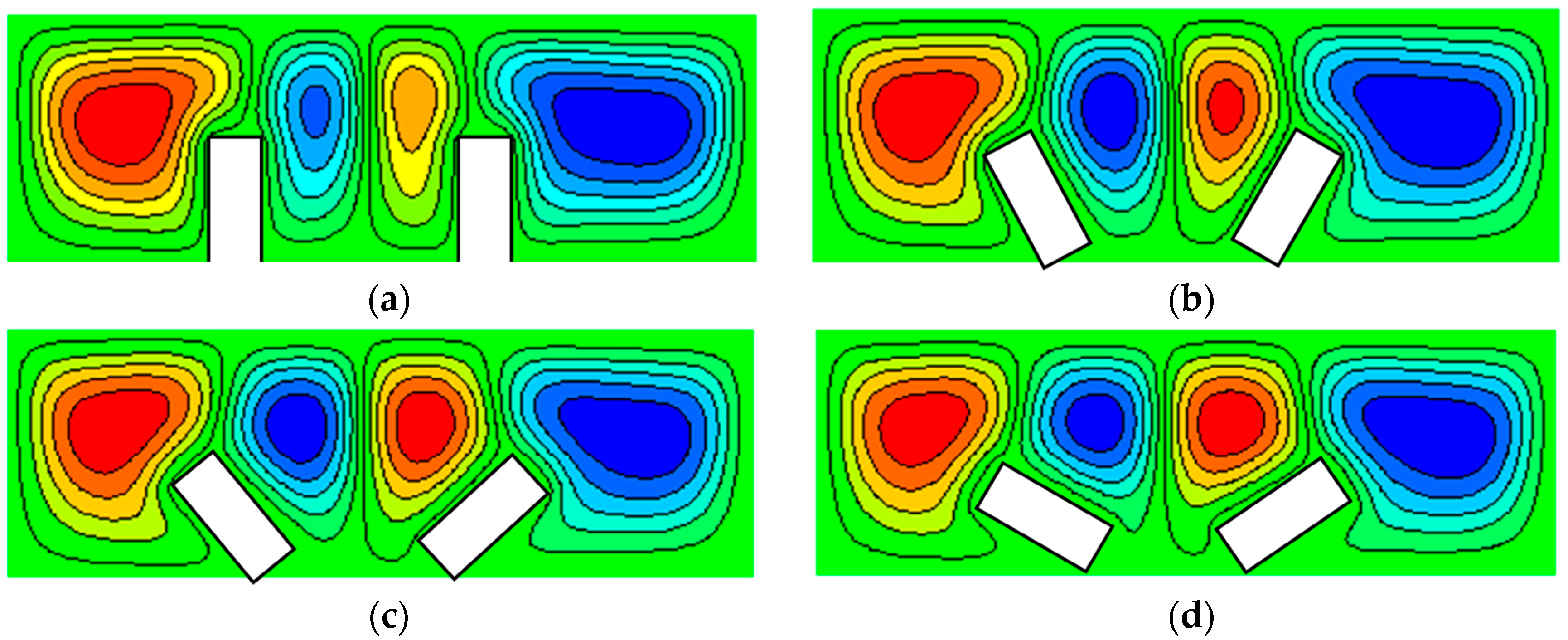
4.1. Effects of Fins’ Geometric Parameters

Figure 4, Figure 5, Figure 6 and Figure 7 depict effects of the inclination angle of the heated-fins on contours of the streamlines, isothermal, and dusty horizontal and vertical veloicties at ϕ A l 2 O 3 =   ϕ C u = 0.02 ,   D s = 10 ,   α s = 0.01 ,   R a = 10 5 ,   L 1 = L 2 = 0.5 and γ = 0.1 . Distributions of the isothermal lines are increased horizontally across the enclosure as the inclination angle of heated fins increases from 0° to 60°. Also, the formation of streamlines inside the enclosure depends on the inclination angle of heated fins. There are four cells of the streamlines around the two heated fins, and the two wider cells are formed near to the enclosure walls. As the inclination angle increases, the wider cells of streamlines are shrinking and the center cells are expanding. The maximum values of the stream function are fluctuating as inclination angle increases from 0° to 60°. In addition, the distributions of the horizontal and vertical dusty velocity contours are depending on the orientation of the heated fins. The maximum of the horizontal and vertical dusty velocities is slightly fluctuating according to an increase on the inclination angle of heated fins shapes. Moreover, the horizontal and vertical dusty velocities along the enclosure are distributed according to variations on the inclination angle.
Figure 8 and Figure 9 present the effects of the heated-fins lengths with two values of an inclination angle γ 1 = 0 ° and 45° on the streamlines and isothermal contours. It is observed that, as expected, the increase in lengths of the heated fins enhances the heated area inside the enclosure and consequently both of the temperature distributions and thermal boundary layers are supported. Also, the inclination of the heated fins makes higher heated area inside the enclosure. In addition, the maximum of the stream function decreases as the lengths of the heated fins are increased. The streamlines form different cells according to lengths and orientation of the heated fins. Figure 10 and Figure 11 show the horizontal and vertical dusty velocity contours under effects of the inclination angle of the heated-fins at ϕ A l 2 O 3 =   ϕ C u = 0.02 ,   D s = 10 ,   α s = 0.01 ,   R a = 10 5 and γ = 0.1 . From these figures, the maximum of the horizontal and vertical dusty velocities increases as the heated fins’ lengths increase from 0.3 to 0.6.

4.2. Effects of Hybrid Nanofluids

Figure 12 shows effects of the nanoparticle volume fraction for hybrid nanofluid on contours of the isotherms, streamlines, horizontal and vertical velocities of the dusty fluid at L 1 = L 2 = 0.5 ,   D s = 10 ,   α s = 0.01 ,   R a = 10 5   ,   γ 1 = 45 ° and γ = 0.1 . Generally, an increase in the nanoparticle volume fraction enhances the viscosity of the fluid and hence the fluid activity is reduced. This can be proved from observing the maximum value of the stream function, at ϕ A l 2 O 3 = ϕ C u = 1 % , ( | ψ | max = 2.8613 ) and at ϕ A l 2 O 3 = ϕ C u = 4 % , ( | ψ | max = 2.7907 ) . Similar trends occur on the maximum values of horizontal and vertical velocities, when ϕ A l 2 O 3 = ϕ C u = 1 % ( | u s | max = 0.1485 ,   | v s | max = 0.2422 ) and at ϕ A l 2 O 3 = ϕ C u = 4 % , ( | u s | max = 0.1414 ,   | v s | max = 0.2192 ) . The isotherms are slightly affected by adding the nanoparticles inside the enclosure.
Figure 13 presents the isothermal dusty contours under the effects of the mixture densities ratio at inclination angle γ 1 = 45 ° , ϕ A l 2 O 3 =   ϕ C u = 0.02 ,   α s = 0.001 ,   R a = 10 5 , at L 1 = L 2 = 0.5 and γ = 0.1 . From these invitigations, effects of the mixture densities ratio on the isothermal dusty contours appear only at low dusty parameter ( α s = 0.001 ) . From this figure, the distributions of the isothermal dusty contours decrease when the mixture densities ratio D s increases from 100 to 1000. The variations of mixture densities ratio from 1 to 100 have slight effects on the isothermal dusty contours.

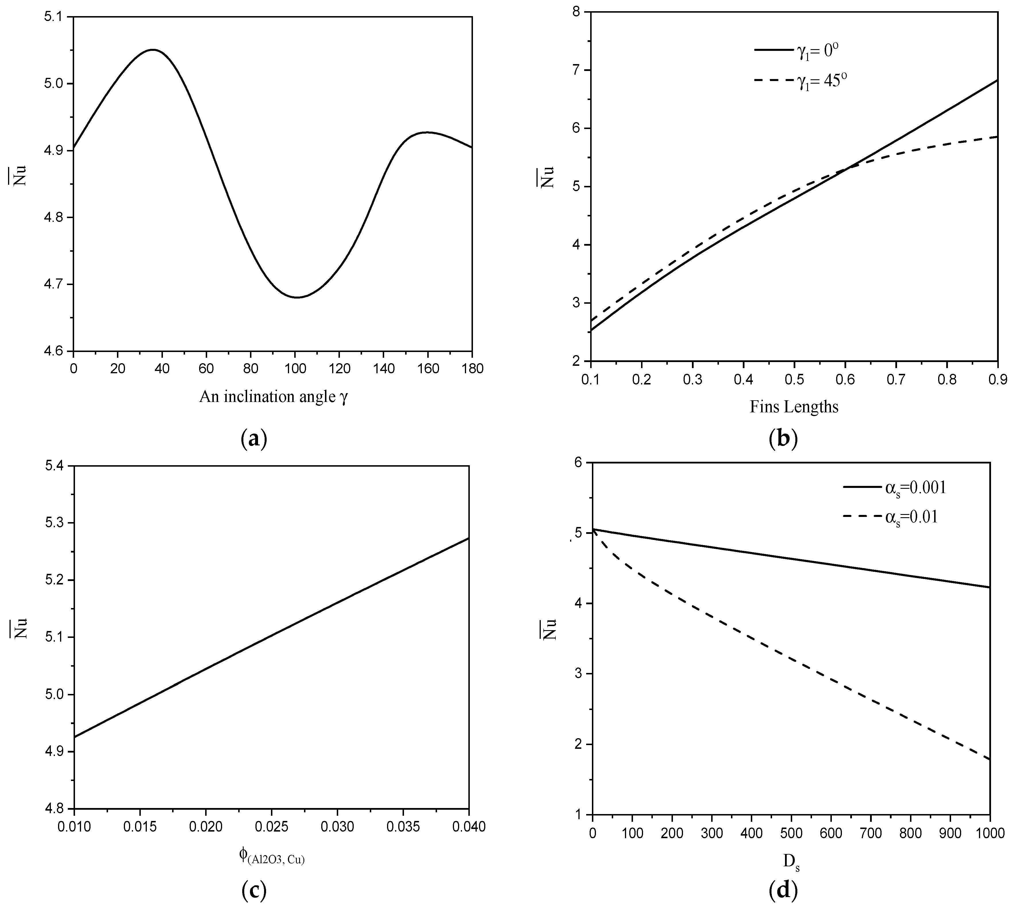
4.3. Local and Average Nusselt Number

Figure 14 shows the local Nusselt number along X -axis under the effects of (a) an inclination angle, (b) fins lengths with two values of an inclination angle, (c) nanoparticle volume fraction for hybrid nanofluid, and (d) mixture densities ratio with two values of dusty parameter, at R a = 10 5 and γ = 0.1 . It is observed that, the inclination angle affects the local Nusselt number along the X -axis without uniform tendency. Also, there are maximum values of the local Nusselt number that occurred at different locations along X -axis particulary, at the range 0.5 X 2.5 . As the fins lengths increase from 0.1 to 0.6, the local Nusselt number increases with three different peaks near to the location of the heated fins. The third results showed that the local Nusslet number is enhanced with a small rate as the nanoparticles volume fraction of hybrid nanofluid increase from 1 % to 4 % . Finally, in case of the low dusty parameter ( α s = 0.001 ) , effects of the mixture densities ratio on the local Nusselt number appear only when the mixture densities ratio D s equals 1000 and then the local Nusselt number decreases clearly as D s increases from 100 to 1000. While in case of the higher dusty parameter ( α s = 0.01 ) , the effects of D s on the local Nusselt number appear soon from D s = 10 to 100 and lowest values of local the Nusselt number at α s = 0.01 with D s = 1000 . The physical explanation of this behavior is due to the fact that the carrier fluid loses kinetic energy by loading the dust particles and this factor leads to a reduced rate of the heat transfer. Figure 15 depicts the average Nusselt number under the effects of (a) an inclination angle, (b) fins lengths with two values of an inclination angle, (c) solid volume fraction for hybrid nanofluid, and (d) mixture densities ratio with two values of dusty parameter. As the inclination angle increases from 0° to 180°, the average Nusselt number is fluctuating between increasing or decreasing. The average Nusselt number is increasing between 0° to 45°, decreasing between 45° to 100° and increasing between 100° to 180°. As the heated fins lengths increase from L 1 = L 2 = 0.1 to 0.9 this enhances the average Nusselt number. The average Nusselt number is higher at an inclination angle 45° compared to 0° when fins lengths vary from 0.1 to 0.6 only. The third results exposed that the average Nusselt is enhanced as the nanoparticles volume fraction increases due to the increase in the thermal conductivity of the nanofluid. At the end, the average Nusselt number is decreasing as the mixture densities ratio increases especially at a higher dusty parameter ( α s = 0.01 ) and a slight decrease on the average Nusselt number occurs at a lower dusty parameter ( α s = 0.001 ) .
Figure 16 presents the time-dependent of isothermal contours for three values of heated-fin lengths L 1 = L 2 = 0.3 ,   0.5 and 0.9 at an inclination angle γ 1 = 45 ° , ϕ A l 2 O 3 =   ϕ C u = 0.02 ,   D s = 10 ,   α s = 0.01 ,   R a = 10 5 and γ = 0.1 . In this figure, the transition of the isothermal distributions across the cavity from the initial to the final was introduced for three values of heated-fin lengths L 1 = L 2 = 0.3 ,   0.5 and 0.9. In this figure, the formation of hot layers around the heated fins are increase as the times increase. In addition, an increase of the fin lengths enhances the heated area inside the enclosure and consequently the thermal boundary layers are supported.

5. Conclusions

Numerical simulations have been performed to study the natural convection flow of dusty hybrid nanofluids inside shallow cavities; those include two rotating heated fins. One of the fins rotates in the clockwise direction and the other rotates in the opposite direction (anticlockwise). This phenomenon was presented by two systems of partial differential equations for the hybrid nanofluid phase and dusty phase. Two SIMPLE algorithms were performed to evaluate the pressures for the hybrid nanofluid and dusty phases. The main results of this simulation can be summarized as follows:
  • There are minimum values of the local Nusselt number that occur at the center of the top wall. Also, the increases in the fins lengths enhance the rate of heat transfer regardless of the values of the inclination angle.
  • For the low values of the lengths of the fins, the vertical fins are the best for the heat transfer compared with the rotating fins.
  • A clear reduction in the heat transfer rate is obtained as a ratio of the mixture densities increases. Also, like the effects of the mixture density ratio, the increase in the dusty parameter reduces the average Nusselt number.
  • A good support in profiles of the average Nusselt number is observed as the nanoparticles’ volume fraction increases.
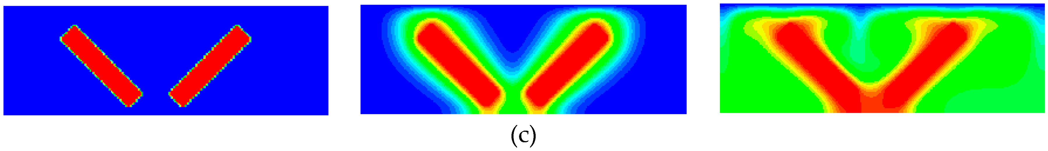
  • The maximum values of the streamlines and dusty velocity components are diminished as values of the nanoparticles’ volume fraction decreases.

Funding

This research was funded by King Khalid University, grant number R.G.P1./147/40.

Acknowledgments

The authors would like to extend their appreciations to the Deanship of Scientific Research at King Khalid University for funding their work through research groups program under grant (R.G.P1./147/40).

Conflicts of Interest

The authors declare no conflict of interest.

Nomenclature

C p specific heat
D s ratio of the mixture densities
g gravitational acceleration, m / s 2
k thermal conductivity, W   m 1 K 1
L 1 , L 2 lengths of left and right fins
N u Nusselt number
P pressure, N / m 2
P r Prandtl number
Q ˙ heat generation parameter
R a Rayleigh number
s 1 , s 2 fin location in the enclosure
T temperature, K
t time, s
u ,   v dimension velocity components, m s
x ,   y Cartesian coordinates, m
Greek Symbols
α thermal diffusivity, m 2 / s
α s dusty parameter
γ ratio of the specific heat
γ 1 Inclined angel
ϕ nanoparticle volume fraction
μ viscosity
θ dimensionless temperature
ν kinematic viscosity, m 2 / s
ρ density, kg / m 3 .
τ T mass concentration of the particle
τ dimensionless time
Subscripts
f hybrid nanofluid
Hhot
Ccold
s particles

References

  1. Rudinger, G. Chapter 4—Thermodynamics of Gas—Particle Mixtures. In Fundamentals of Gas Particle Flow; Rudinger, G., Ed.; Elsevier: Amsterdam, The Netherlands, 1980; pp. 40–52. [Google Scholar]
  2. Farbar, L.; Morley, M. Heat transfer to flowing gas-solids mixtures in a circular tube. Ind. Eng. Chem. 1957, 49, 1143–1150. [Google Scholar] [CrossRef]
  3. Singleton, R.E. Fluid Mechanics of Gas-Solid Particle Flow in Boundary Layers; California Institute of Technology: Pasadena, California, CA, USA, 1964. [Google Scholar]
  4. Gireesha, B.J.; Bagewadi, C.S.; Prasannakumar, B.C. Pulsatile flow of an unsteady dusty fluid through rectangular channel. Commun. Nonlinear Sci. Numer. Simul. 2009, 14, 2103–2110. [Google Scholar] [CrossRef]
  5. Manjunatha, P.T.; Gireesha, B.J.; Prasannakumara, B.C. Thermal analysis of conducting dusty fluid flow in a porous medium over a stretching cylinder in the presence of non-uniform source/sink. Int. J. Mech. Mater. Eng. 2014, 9, 13. [Google Scholar] [CrossRef]
  6. Mahanthesh, B.; Gireesha, B. Thermal Marangoni convection in two-phase flow of dusty Casson fluid. Results Phys. 2018, 8, 537–544. [Google Scholar] [CrossRef]
  7. Ghadikolaei, S.S.; Hosseinzadeh, K.; Ganji, D.D.; Hatami, M. Fe3O4-(CH2OH)2 nanofluid analysis in a porous medium under MHD radiative boundary layer and dusty fluid. J. Mol. Liq. 2018, 258, 172–185. [Google Scholar] [CrossRef]
  8. Siddiqa, S.; Begum, N.; Hossain, M.A.; Gorla, R.S.R.; Al-Rashed, A.A.A.A. Two-phase natural convection dusty nanofluid flow. Int. J. Heat Mass Transf. 2018, 118, 66–74. [Google Scholar] [CrossRef]
  9. Isa, S.M.; Mohammad, N.F. Boundary Layer Flow of Dusty Fluid on a Stretching Sheet of Another Quiescent Fluid. J. Phys. Conf. 2017, 819, 012027. [Google Scholar] [CrossRef] [Green Version]
  10. Dalal, D.; Datta, N.; Mukherjea, S. Unsteady natural convection of a dusty fluid in an infinite rectangular channel. Int. J. Heat Mass Transf. 1998, 41, 547–562. [Google Scholar] [CrossRef]
  11. Saba, F.; Ahmed, N.; Khan, U.; Waheed, A.; Rafiq, M.; Mohyud-Din, S. Thermophysical analysis of water based (Cu–Al2O3) hybrid nanofluid in an asymmetric channel with dilating/squeezing walls considering different shapes of nanoparticles. Appl. Sci. 2018, 8, 1549. [Google Scholar] [CrossRef]
  12. Sheikholeslami, M.; Mehryan, S.A.M.; Shafee, A.; Sheremet, M.A. Variable magnetic forces impact on magnetizable hybrid nanofluid heat transfer through a circular cavity. J. Mol. Liq. 2019, 277, 388–396. [Google Scholar] [CrossRef]
  13. Sekrani, G.; Poncet, S. Ethylene-and Propylene-Glycol Based Nanofluids: A Litterature Review on Their Thermophysical Properties and Thermal Performances. Appl. Sci. 2018, 8, 2311. [Google Scholar] [CrossRef]
  14. Mehryan, S.A.M.; Kashkooli, F.M.; Ghalambaz, M.; Chamkha, A.J. Free convection of hybrid Al2O3-Cu water nanofluid in a differentially heated porous cavity. Adv. Powder Technol. 2017, 28, 2295–2305. [Google Scholar] [CrossRef]
  15. Hussain, S.; Ahmed, S.E.; Akbar, T. Entropy generation analysis in MHD mixed convection of hybrid nanofluid in an open cavity with a horizontal channel containing an adiabatic obstacle. Int. J. Heat Mass Transf. 2017, 2017 114, 1054–1066. [Google Scholar] [CrossRef]
  16. Mansour, M.; Siddiqa, S.; Gorla, R.S.R.; Rashad, A. Effects of heat source and sink on entropy generation and MHD natural convection of Al2O3-Cu/water hybrid nanofluid filled with square porous cavity. Therm. Sci. Eng. Prog. 2018, 6, 57–71. [Google Scholar] [CrossRef]
  17. Ashorynejad, H.R.; Shahriari, A. MHD natural convection of hybrid nanofluid in an open wavy cavity. Results Phys. 2018, 9, 440–455. [Google Scholar] [CrossRef]
  18. Ghadikolaei, S.; Hosseinzadeh, K.; Hatami, M.; Ganji, D.D. MHD boundary layer analysis for micropolar dusty fluid containing Hybrid nanoparticles (Cu-Al2O3) over a porous medium. J. Mol. Liq. 2018, 268, 813–823. [Google Scholar] [CrossRef]
  19. Chamkha, A.; Dogonchi, A.; Ganji, D. Magnetohydrodynamic nanofluid natural convection in a cavity under thermal radiation and shape factor of nanoparticles impacts: A numerical study using CVFEM. Appl. Sci. 2018, 8, 2396. [Google Scholar] [CrossRef]
  20. Mozaffari, S.; Tchoukov, P.; Atias, J.; Czarnecki, J.; Nazemifard, N. Effect of asphaltene aggregation on rheological properties of diluted athabasca bitumen. Energy Fuels 2015, 29, 5595–5599. [Google Scholar] [CrossRef]
  21. Darjani, S.; Koplik, J.; Pauchard, V. Extracting the equation of state of lattice gases from random sequential adsorption simulations by means of the Gibbs adsorption isotherm. Phys. Rev. E 2017, 96, 052803. [Google Scholar] [CrossRef] [Green Version]
  22. Mozaffari, A.; Sharifi-Mood, N.; Koplik, J.; Maldarelli, C. Self-diffusiophoretic colloidal propulsion near a solid boundary. Phys. Fluids 2016, 28, 053107. [Google Scholar] [CrossRef] [Green Version]
  23. Mozaffari, S.; Tchoukov, P.; Mozaffari, A.; Atias, J.; Czarnecki, J.; Nazemifard, N. Capillary driven flow in nanochannels—Application to heavy oil rheology studies. Colloids Surf. A Physicochem. Eng. Asp. 2017, 513, 178–187. [Google Scholar]
  24. Hosseini, S.B.; Khoshkhoo, R.H.; Malabad, S.J. Numerical study on polydisperse particle deposition in a compact heat exchanger. Appl. Therm. Eng. 2017, 127, 330–346. [Google Scholar] [CrossRef]
  25. Liu, Y.; Lei, C.; Patterson, J.C. Natural convection in a differentially heated cavity with two horizontal adiabatic fins on the sidewalls. Int. J. Heat Mass Transf. 2014, 72, 23–36. [Google Scholar] [CrossRef]
  26. Varol, Y.; Özgen, F. Effect of inclined thick fin on natural convection in a cavity heated from bottom. Comput. Fluid Dyn. 2015, 15, 47–55. [Google Scholar] [CrossRef]
  27. Kolsi, L.; Oztop, H.F.; Abu-Hamdeh, N.; Alghamdi, A.; Borjini, M.N. Three dimensional analysis of natural convection and entropy generation in a sharp edged finned cavity. Alex. Eng. J. 2016, 55, 991–1004. [Google Scholar] [CrossRef] [Green Version]
  28. Elatar, A.; Teamah, M.A.; Hassab, M.A. Numerical study of laminar natural convection inside square enclosure with single horizontal fin. Int. J. Therm. Sci. 2016, 99, 41–51. [Google Scholar] [CrossRef]
  29. Ma, J.; Xu, F. Unsteady natural convection and heat transfer in a differentially heated cavity with a fin for high Rayleigh numbers. Appl. Therm. Eng. 2016, 99, 625–634. [Google Scholar] [CrossRef]
  30. Azimifar, A.; Payan, S. Optimization of characteristics of an array of thin fins using PSO algorithm in confined cavities heated from a side with free convection. Appl. Therm. Eng. 2017, 110, 1371–1388. [Google Scholar] [CrossRef]
  31. Torabi, M.; Keyhani, A.; Peterson, G. A comprehensive investigation of natural convection inside a partially differentially heated cavity with a thin fin using two-set lattice Boltzmann distribution functions. Int. J. Heat Mass Transf. 2017, 115, 264–277. [Google Scholar]
  32. Imani, G. Three dimensional lattice Boltzmann simulation of steady and transient finned natural convection problems with evaluation of different forcing and conjugate heat transfer schemes. Comput. Math. Appl. 2017, 74, 1362–1378. [Google Scholar] [CrossRef]
  33. Hatami, M. Numerical study of nanofluids natural convection in a rectangular cavity including heated fins. J. Mol. Liq. 2017, 233, 1–8. [Google Scholar] [CrossRef]
  34. Gao, D.; Chen, Z.; Zhang, D.; Chen, L. Lattice Boltzmann modeling of melting of phase change materials in porous media with conducting fins. Appl. Therm. Eng. 2017, 118, 315–327. [Google Scholar] [CrossRef]
  35. Ghalambaz, M.; Jamesahar, E.; Ismael, M.A.; Chamkha, A.J. Fluid-structure interaction study of natural convection heat transfer over a flexible oscillating fin in a square cavity. Int. J. Therm. Sci. 2017, 111, 256–273. [Google Scholar] [CrossRef]
  36. Alnaqi, A.A.; Aghakhani, S.; Pordanjani, A.H.; Bakhtiari, R.; Asadi, A.; Tran, M.-D. Effects of magnetic field on the convective heat transfer rate and entropy generation of a nanofluid in an inclined square cavity equipped with a conductor fin: Considering the radiation effect. Int. J. Heat Mass Transf. 2019, 133, 256–267. [Google Scholar] [CrossRef]
  37. Sarkar, J.; Ghosh, P.; Adil, A. A review on hybrid nanofluids: Recent research, development and applications. Renew. Sustain. Energy Rev. 2015, 43, 164–177. [Google Scholar] [CrossRef]
  38. Aly, A.M.; Raizah, Z.; Ahmed, S.E. Mixed Convection in a Cavity Saturated with Wavy Layer Porous Medium: Entropy Generation. J. Thermophys. Heat Transf. 2018, 32, 1–17. [Google Scholar] [CrossRef]
  39. Aly, A.M.; Ahmed, S.E.; Raizah, Z. Double-diffusive natural convection in a square porous cavity with sinusoidal distributions side walls filled with a nanofluid. J. Porous Media 2018, 21, 101–122. [Google Scholar] [CrossRef]
  40. Aly, A.M.; Raizah, Z.; Ahmed, S.E. Natural convection in an enclosure saturatedwith multilayer porous medium and nanofluid over circular cylinders: entropy generation. J. Porous Media 2018, 21, 1007–1024. [Google Scholar] [CrossRef]
  41. Aly, A.M. Double-diffusive natural convection in a non-darcy porous cavity filled with nanofluid under the effects of chemical reaction. J. Porous Media 2017, 20, 111–126. [Google Scholar] [CrossRef]
  42. Aly, A.M. Natural convection over circular cylinders in a porous enclosure filled with a nanofluid under thermo-diffusion effects. J. Taiwan Inst. Chem. Eng. 2017, 70, 88–103. [Google Scholar] [CrossRef]
  43. Ahmed, S.E.; Raizah, Z.A.S. Natural Convection Flow of Nanofluids in a Composite System with Variable-Porosity Media. J. Thermophys. Heat Transf. 2018, 32, 495–502. [Google Scholar] [CrossRef]
  44. Ahmed, S.E.; Elshehabey, H.M. Buoyancy-driven flow of nanofluids in an inclined enclosure containing an adiabatic obstacle with heat generation/absorption: Effects of periodic thermal conditions. Int. J. Heat Mass Transf. 2018, 124, 58–73. [Google Scholar] [CrossRef]
  45. Grosan, T.; Revnic, C.; Pop, I.; Ingham, D.B. Magnetic field and internal heat generation effects on the free convection in a rectangular cavity filled with a porous medium. Int. J. Heat Mass Transf. 2009, 52, 1525–1533. [Google Scholar] [CrossRef]
Figure 1. Physical model and coordinates system.
Applsci 09 02673 g001
Figure 2. Grid study at ϕ A l 2 O 3 = ϕ C u = 0.02 , D s = 10 , α s = 0.01 , R a = 10 5 , L 1 = L 2 = 0.5 , γ 1 = 45 , and γ = 0.1 .
Applsci 09 02673 g002
Figure 3. Comparison of the (a) streamlines and (b) isotherms contours between the present results (left) and Hatami [33] (right).
Applsci 09 02673 g003aApplsci 09 02673 g003b
Figure 4. Isothermal contours under the effects of an inclination angle of heated-fins at ϕ A l 2 O 3 =   ϕ C u = 0.02 ,   D s = 10 ,   α s = 0.01 ,   R a = 10 5 ,   L 1 = L 2 = 0.5 and γ = 0.1 . (a) γ 1 = 0 ° ; (b) γ 1 = 30 ° ; (c) γ 1 = 45 ° ; (d) γ 1 = 60 ° .
Applsci 09 02673 g004aApplsci 09 02673 g004b
Figure 5. Streamlines contours under the effects of an inclination angle of heated-fins at ϕ A l 2 O 3 =   ϕ C u = 0.02 ,   D s = 10 ,   α s = 0.01 ,   R a = 10 5 ,   L 1 = L 2 = 0.5 and γ = 0.1 . (a) γ 1 = 0 °   ( | ψ | max = 2.8446 ) ; (b) γ 1 = 30 °   ( | ψ | max = 2.7720 ) ; (c) γ 1 = 45 °   ( | ψ | max = 2.8013 ) ; (d) γ 1 = 60 °   ( | ψ | max = 2.7946 ) .
Applsci 09 02673 g005
Figure 6. Horizontal dusty velocity contours under the effects of an inclination angle of heated-fins at ϕ A l 2 O 3 =   ϕ C u = 0.02 ,   D s = 10 ,   α s = 0.01 ,   R a = 10 5 ,   L 1 = L 2 = 0.5 and γ = 0.1 . (a) γ 1 = 0 °   ( | u s | max = 0.1468 ) ; (b) γ 1 = 30 ° ,   ( | u s | max = 0.1463 ) ; (c) γ 1 = 45 °   ( | u s | max = 0.1464 ) ; (d) γ 1 = 60 °   ( | u s | max = 0.1457 ) .
Applsci 09 02673 g006
Figure 7. Vertical dusty velocity contours under the effects of an inclination angle of heated-fins at ϕ A l 2 O 3 =   ϕ C u = 0.02 ,   D s = 10 ,   α s = 0.01 ,   R a = 10 5 ,   L 1 = L 2 = 0.5 and γ = 0.1 . (a) γ 1 = 0 ° , ( | v s | max = 0.2195 ) ; (b)   γ 1 = 30 °   ; ( | v s | max = 0.1463 ) ; (c) γ 1 = 45 °   , ( | v s | max = 0.2341 ) ; (d) γ 1 = 60 ° ,   ( | v s | max = 0.2229 ) .
Applsci 09 02673 g007aApplsci 09 02673 g007b
Figure 8. Isothermal contours under the effects of heated-fins lengths with two values of an inclination angle γ 1 = 0 ° (top row) and 45° (second row) at ϕ A l 2 O 3 =   ϕ C u = 0.02 ,   D s = 10 ,   α s = 0.01 ,   R a = 10 5 and γ = 0.1 . (a) L 1 = L 2 = 0.3 ; (b) L 1 = L 2 = 0.6 ; (c) L 1 = L 2 = 0.9 ; (d) L 1 = L 2 = 0.3 ; (e) L 1 = L 2 = 0.6 ; (f) L 1 = L 2 = 0.9 .
Applsci 09 02673 g008
Figure 9. Streamlines contours under the effects of heated-fins lengths with two values of an inclination angle γ 1 = 0 ° (top row) and 45° (second row) at ϕ A l 2 O 3 =   ϕ C u = 0.02 , D s = 10 ,   α s = 0.01 , R a = 10 5 and γ = 0.1 . (a) L 1 = L 2 = 0.3 , ( | ψ | max = 2.9405 ) ; (b) L 1 = L 2 = 0.6 , ( | ψ | max = 2.8480 ) ; (c) L 1 = L 2 = 0.9 , ( | ψ | max = 2.8227 ) ; (d) L 1 = L 2 = 0.3 , ( | ψ | max = 3.0054 ) ; (e) L 1 = L 2 = 0.6 , ( | ψ | max = 2.7263 ) ; (f) L 1 = L 2 = 0.9 , ( | ψ | max = 2.5927 ) .
Applsci 09 02673 g009
Figure 10. Horizontal dusty velocity contours under the effects of heated-fins lengths at inclination angle γ 1 = 0 ° , ϕ A l 2 O 3 =   ϕ C u = 0.02 ,   D s = 10 ,   α s = 0.01 ,   R a = 10 5 and γ = 0.1 . (a) L 1 = L 2 = 0.3 , ( | u s | max = 0.1399 ) ; (b) L 1 = L 2 = 0.6 , ( | u s | max = 0.1477 ) .
Applsci 09 02673 g010
Figure 11. Vertical dusty velocity contours under the effects of heated-fins lengths at inclination angle γ 1 = 0 ° , ϕ A l 2 O 3 =   ϕ C u = 0.02 ,   D s = 10 ,   α s = 0.01 ,   R a = 10 5 and γ = 0.1 . (a) L 1 = L 2 = 0.3 , ( | v s | max = 0.1993 ) ; (b) L 1 = L 2 = 0.6 , ( | v s | max = 0.2169 ) .
Applsci 09 02673 g011
Figure 12. Effects of nanoparticle volume fraction for hybrid nanofluid on contours of (a) isothermal lines; (b) streamlines; (c) horizontal dusty velocity; (d) vertical velocity of dusty fluid at L 1 = L 2 = 0.5 ,   D s = 10 ,   α s = 0.01 ,   R a = 10 5   ,   γ 1 = 45 ° and γ = 0.1 .
Applsci 09 02673 g012aApplsci 09 02673 g012b
Figure 13. Isothermal dusty contours under the effects of mixture densities ratio at inclination angle γ 1 = 45 ° , ϕ A l 2 O 3 =   ϕ C u = 0.02 ,   α s = 0.001 ,   R a = 10 5 , at L 1 = L 2 = 0.5 and γ = 0.1 . (a) D s = 1 ; (b) D s = 10 ; (c) D s = 100 ; (d) D s = 1000 .
Applsci 09 02673 g013
Figure 14. Local Nusselt number along X-axis under the effects of (a) an inclination angle, (b) fins lengths with two values of an inclination angle, (c) nanoparticle volume fraction for hybrid nanofluid, and (d) mixture densities ratio with two values of dusty parameter at R a = 10 5 and γ = 0.1 .
Applsci 09 02673 g014
Figure 15. Average Nusselt number under the effects of (a) an inclination angle, (b) fins lengths with two values of an inclination angle, (c) solid volume fraction for hybrid nanofluid, and (d) mixture densities ratio with two values of dusty parameter, at R a = 10 5 and γ = 0.1 .
Applsci 09 02673 g015
Figure 16. Time-dependence of isothermal contours for two values of heated-fin lengths L 1 = L 2 = 0.3 ,   0.5 and 0.9 at an inclination angle γ 1 = 45 ° , ϕ A l 2 O 3 =   ϕ C u = 0.02 , D s = 10 , α s = 0.01 , R a = 10 5 and γ = 0.1 . (a) L 1 = L 2 = 0.3 ; (b) L 1 = L 2 = 0.5 ; (c) L 1 = L 2 = 0.9 .
Applsci 09 02673 g016aApplsci 09 02673 g016b
Table 1. Thermo-physical properties of the base fluid and nanoparticles.
PropertyWaterCopper (Cu)Alumina (Al2O3)
ρ (kg/m3)997.189333970
C p (J/kg·K)4179385765
k (W/m·K)0.61340140
β (1/K)21 × 10−51.67 × 10−50.85 × 10⁻⁵
Table 2. Comparisons of the maximum values of the stream function and isotherms at R a = 10 3 ,   ϕ A l 2 O 3 =   ϕ C u = 0 % ,   D s = 0 ,   α s = 0 .
FunctionGrosan at al. [45]PresentsError
ψ M a x 3.51323.53380.58%
θ M a x 0.09850.0973591.16%

