Abstract
Based on the horizontal slice method (HSM) and assuming a log spiral slip surface, a method to analyze the stability of a reinforced retaining wall under seismic loads was established in this study by calculating the tensile force of the reinforcement. A parametric study was conducted on the normalized tensile force of the reinforcement, and it was observed that the normalized tensile force tends to increase with acceleration of the seismic load and the height of the backfill. Moreover, it also increases with soil unit weight, while it decreases with increased friction angle of the backfill soil, and the influence of soil cohesion on the normalized tensile force is not significant. The HSM method is proved to be suitable for analyzing the tensile force of reinforcement in retaining walls under seismic loads.
1. Introduction
The reinforced retaining wall is a composite structure widely adopted in seismic regions due to its excellent deformation characteristics under seismic loads, such as earthquakes, owing to the friction between the reinforcement and the soil [1,2,3,4,5,6,7,8,9,10]. Okabe [11] proposed the Mononobe–Okabe method, which has been applied in analyzing the stability of reinforced retaining walls under dynamic loads [12]. Zeng and Steedman [13] studied the propagation of the shear wave in the backfill of a retaining wall by the pseudodynamic method and validated the analysis by centrifuge tests. Based on the pseudostatic method, Ling and Leshchinsky [14] and Kwak [15] investigated the vertical seismic response of reinforced soil structures under earthquake conditions. Shahgoli et al. [16] adopted the horizontal slice method (HSM) to analyze the stability of reinforced soil structures subjected to seismic loads. Choudhury and Singh [17] used the pseudostatic method to calculate the active earth pressure behind a retaining wall under seismic load. The slip surface of the reinforced retaining wall was also detected by vibration table tests [18,19], and it was found that the slip surface was like a log spiral. However, the mechanism of collaboration between reinforcement and soil remains unclear. Calculation of the tensile force of the reinforcement is still far from being fully understood and established [20,21]. Based on HSM and log spiral slip surface [16,22,23], the collaborative work of reinforcement and soils is considered in this study to establish a method of analyzing the stability of a reinforced retaining wall under seismic loads. Calculation of the tensile force of the reinforcement is carried out by considering the influence of soil parameters and loading conditions [24,25]. The slice method is proposed to determine the critical failure angle of the backfill wedge under complex conditions, and an iterative calculation method is presented to determine the tension crack depth of the active earth pressure under seismic loads [26,27]. The axial stress of the anchor is greatly increased by seismic excitation, and the increment is mainly induced within the excitation period of great acceleration amplitude, evaluation of the effect of earthquake frequency content on seismic behavior of cantilever retaining wall including soil–structure interaction [28,29]. By taking the failure surface as a plane, the analytical expression for the critical angle of the failure surface, earthquake-induced displacements of gravity retaining walls and anchor-reinforced slopes are also derived [30,31].
A critical review of literature shows that a very few studies have been reported for the stability analysis of a reinforced retaining wall. The present paper extends the latter work by developing a number of formulations, including a pseudostatic method of analysis. The formulations are described and compared with other published methods used for the seismic analysis of reinforced soil structures. However, no study seems to be available to quantify the effect of seismic acceleration coefficients and soil and reinforcing structure on the stability of reinforced soil walls. In view of this observation, the present study is directed to conduct a seismic stability analysis of the reinforced retaining wall using the HSM and considering the pseudo static forces. The limit equilibrium equation of a reinforced retaining wall under seismic loads is established, and the formula for calculating the tensile force in reinforcement is proposed to address the stability of reinforced retaining wall. In the end, the parametric study has been carried out to investigate the effect of various parameters like reinforcing structure, angle of internal friction and cohesion of soil, horizontal seismic loading.
2. Assumptions and Formulation of the Horizontal Slice Method (HSM)
2.1. Basic Assumptions of HSM
In the HSM approach, the sliding wedge is divided into horizontal slices with rigid-plastic behavior. The seismic force is considered as a pseudostatic force acting at the center of gravity of each slice [23]. The geotechnical interaction between the reinforcing structure and the surrounding soil is ignored. The assumptions are as follows:
- (1)
- The log spiral slip surface line of the reinforced retaining wall passes through the toe of the wall.
- (2)
- The sliding body of the retaining wall is divided into several horizontal slices, the number of which is equal to that of reinforcement layers, and each slice contains reinforcement [32].
- (3)
- The horizontal shear force between reinforcements is ignored.
- (4)
- The safety factor is assumed to be equal for various slices [23].
- (5)
- Both horizontal and vertical seismic actions are applied to the center of gravity of the slice.
- (6)
- The analysis is done by the limited equilibrium method.
- (7)
- The anchoring strength of the reinforcement and the resistance of the reinforcement against pulling out are not taken into account.
2.2. Formulation of the HSM
HSM was proposed by Lo and Xu [22] and was aimed at overcoming the difficulties in analyzing reinforced soil structures by the vertical slice method (Figure 1). In Figure 1, H is the height of the retaining wall (in m); Sy,j denotes the vertical distance between the reinforcement of layer j and layer j+1 (in m), and it is usually treated as a certain value in the design; St,i and NN,i are the shear force and normal force acting on the ith slice, respectively; lai is the length of reinforcement in the slip zone behind the wall; and lei refers to the length of reinforcement in the anchorage zone. Figure 2 zooms in on the ith slice taken from Figure 1, which contains one reinforcement. In the figure, FN,I and FN,i+1 represent the normal force acting on the top and bottom of the ith slice, respectively; Ti refers to the tensile force of the ith reinforcement [33]; Qhi and Qvi denote horizontal and vertical seismic force, respectively, acting on the top of the slice; αi is the inclination angle of slip surface of the slice in the horizontal direction; and Wi is the weight of the ith slice. It should be noted that the slip surface is assumed to be a log spiral shape passing through the toe of the wall [34]. The sliding wedge is assumed to be in a limited equilibrium state, while both horizontal and vertical seismic loads are applied on the center of gravity of the slice. Then the safety for each slice is:
where and refer to shear strength and shear stress on the sliding surface, respectively.
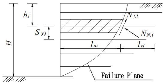
Figure 1.
Illustration of failure mechanism of reinforced wall by the horizontal slice method (HSM) (modified after Jia et al. 2018).
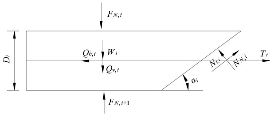
Figure 2.
Forces acting on the ith slice (modified after Jia et al. 2018).
3. Seismic Loads
Under seismic loads, the shear wave velocity and compression wave velocity are characterized as:
where , , and are shear modulus, density, and Poisson’s ratio of soils, respectively. In this study, we assumed is 0.3 for soils, therefore:
The period for the horizontal seismic load is:
and are horizontal and vertical seismic acceleration, respectively. We assumed that the direction of propagation of seismic waves is vertical. Then the acceleration of z deep location from the surface of the retaining wall at moment t is:
The body mass of the element in z with m depth and dz height is:
while the self-weight of the ith slice is:
where is the unit weight of backfill soil, and and are the length of the top and bottom side of the ith slice, respectively.
Horizontal inertia force on the ith element is:
Then the total horizontal seismic load on the slice is:
The vertical inertia force on the ith element is:
Then the total horizontal seismic load on the retaining wall is
where is the vertical wavelength of the shear wave (), and denotes the vertical wavelength of the compression wave (; ). By considering and on the critical direction of the element, the limits of and according to Ling and Leshchinsky [14] are, respectively:
where and . When the ith slice is in limited equilibrium state, the vertical and horizontal stress applied on the slice are and [21,24], then:
4. Tensile Force of Reinforcement
According to the definition of safety factor [21], the shear force at the base of the slice is calculated by Equation (18):
where and are cohesion and friction angle of soil, respectively. The following formula can be obtained by compiling Equations (16) and (18):
Then Equation (19) can be obtained by compiling Equations (17)–(19):
After that, the tensile force of reinforcement is:
For each layer of reinforcement, the tensile force is:
where Sy,j is the vertical distance between reinforcements and hj denotes the vertical distance between the jth reinforcement and the top of the wall. The normalized tensile force K for all reinforcements is [21]:
For the stability analysis of a reinforced retaining wall under seismic loads [35], the maximum tensile force of each reinforcement needs to be calculated by Equation (22). This is also to determine the most critical log spiral slip surface, in which αi is obtained. This problem is the optimal solution of the linear programming problem. Matlab was used to get the interactive solution of and αi.
5. Parametric Study
Figure 3 shows the geometry of the reinforced retaining wall as a case study. It can be seen that the wall is 6 m in height (H). The retaining wall is made of 6 pieces of reinforced concrete panel, each of which has a height of 1 m. The toe of the wall is made of plain concrete, with a width of 0.6 m and buried depth of 0.6 m. The reinforcement is made of metal, with a cross-section of 3 × 0.2 cm. Peak seismic acceleration is assumed to be 0.2 g. Factors affecting the stability of the retaining wall investigated are seismic acceleration coefficients (kh and kv) and soil parameters (c, , and ); parameters for the study can be seen in Table 1.
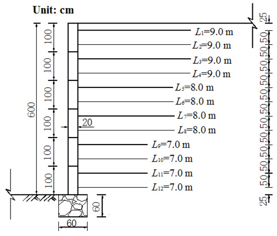
Figure 3.
Geometry of the reinforced retaining wall.

Table 1.
Geometric and geotechnical characteristics of the wall used for the parametric study.
5.1. Influence of Seismic Acceleration Coefficients
Variation of the normalized tensile force K with friction angle was also evaluated for various seismic acceleration coefficients. is fixed as 20 kN/m3, while is c is treated as 0. The horizontal seismic acceleration coefficient kh [36] is calculated by:
while kh and kv need to fulfill the relationship of:
Figure 4 and Figure 5 show the influence of seismic acceleration coefficients on the normalized tensile force, while Figure 6 illustrates the influence of seismic acceleration coefficients on the inclination angle. It can be identified that normalized tensile force increases with the increase of seismic acceleration coefficient, especially when kh is increased from 0.1 to 0.2. Comparing Figure 4; Figure 5 shows that kv also contributes to K, but it only has limited effect. This implies that the horizontal seismic load is the dominant force for a reinforced retaining wall. It also shows that when the friction angle increases, the normalized tensile force will decrease. This means that the use of a well-graded backfill material with a large friction angle will be beneficial to the stability of the reinforced retaining wall under seismic loads [37]. Figure 6 shows that the slip surface is almost linear from the toe to the middle part of the wall, since the variation of the inclination angle for each slice is very small, while from the middle to the top surface of the wall, the slip surface is a vertical line parallel to the wall. It also shows that the slip surface of the retaining wall moves toward the wall side with the increasing seismic load.
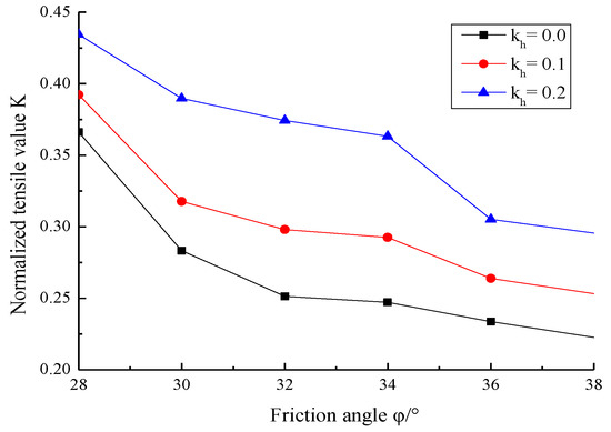
Figure 4.
Normalized tensile force of reinforcement under seismic load when kv = 0.
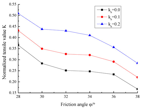
Figure 5.
Normalized tensile force of reinforcement under seismic load when kv = 0.5 kh.
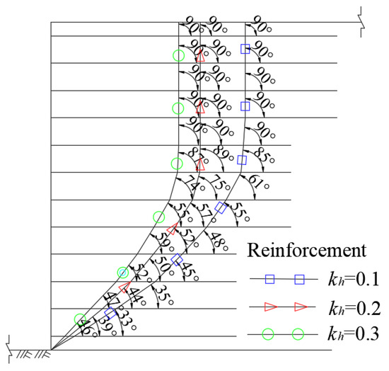
Figure 6.
Inclination angle of slip surface and horizontal direction for various kh.
5.2. Influence of Soil Parameters
Figure 7 shows the influence of cohesion of soil on normalized tensile force (k = 0.5 kh, 20 kN/m3, 33°), while Figure 8 illustrates the influence of cohesion of soil on the inclination angle. It shows that with increased soil cohesion, the normalized tensile force tends to increase, and its increment is obvious. It can be identified from Figure 8 that the slip surface of the retaining wall moves toward the wall side with increasing cohesion. To investigate the effect of soil unit weight, soil cohesion and friction angle are fixed at 10 kPa and 33°, respectively, k = 0.5, and k = 0.2. It can be seen in Figure 9 that bigger unit weight leads to higher normalized tensile force. This implies that better stability of the retaining wall will be achieved by using lightweight backfill materials. Figure 10 illustrates that the slip surface of the retaining wall moves toward the wall side with increasing soil unit weight. Figure 11 shows the influence of soil friction angle on normalized tensile force (k = 0.5, k = 0.2, 20 kN/m3, c = 10 kPa), and that normalized tensile force decreases with the increased soil friction angle. Therefore, increasing the soil friction angle (such as by using some coarse materials) will contribute to the stability of the retaining wall. As demonstrated in Figure 12, the slip surface of the retaining wall moves toward the wall side with increments of friction angle.
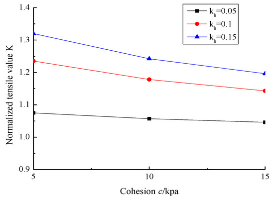
Figure 7.
Effect of cohesion on normalized tensile force of reinforcement.
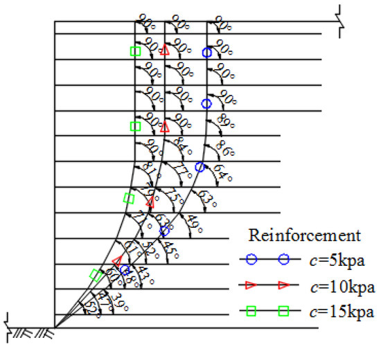
Figure 8.
Inclination angle of slip surface and horizontal direction for various levels of cohesion.
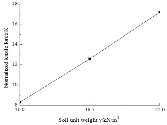
Figure 9.
Effect of soil unit weight on normalized tensional force of reinforcement.
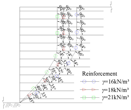
Figure 10.
Inclination angle of slip surface and horizontal direction for various unit weights.
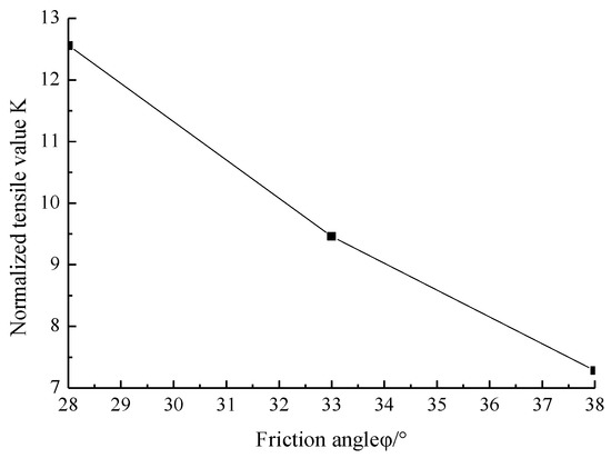
Figure 11.
Effect of soil friction angle on normalized tensional force of reinforcement.
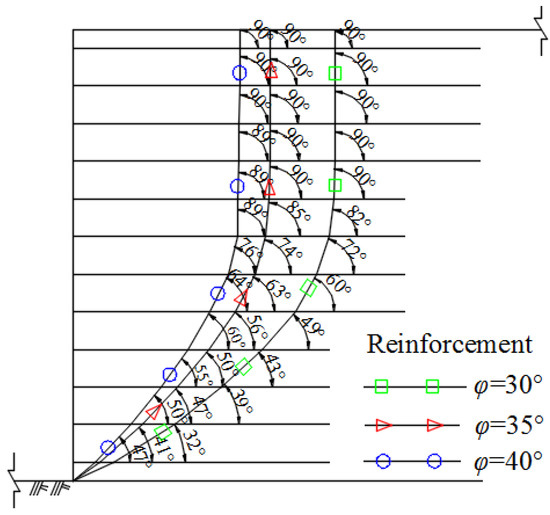
Figure 12.
Inclination angle of slip surface and horizontal direction for various friction angles.
5.3. Influence of the Reinforcing Structure
Vertical distance between reinforcements (Sy,j) is the main parameter influencing the tensile force of the reinforcement. It can be identified from Equation (22) that tensile force has a positive relationship with the vertical distance between reinforcements. In other words, the tensile force will increase with increasing vertical distance between reinforcements. Thus, reducing the vertical distance between reinforcements is beneficial to reduce the tensile force, which is favorable for wall stability. Equation (22) also indicates that the reinforcing structure will not have a direct impact on the slip surface of the retaining wall.
5.4. Discussion
Based on a parametric analysis of the tensile force of reinforcement in a retaining wall, it can be seen that the horizontal seismic load, the vertical distance between reinforcements, and the soil friction angle are the three dominant factors influencing the tensile force. The findings are in agreement with Saeed and Ali [38] and Nouri et al. [23,32,39]. Vertical seismic load and soil cohesion have an insignificant impact on the tensile force of reinforcement, which is also close to the conclusions drawn by Nimbalkar et al. [34], Syed et al. [40], and Chandaluri et al. [41]. In summary, the HSM method adopted in this study could lead to similar results from a pseudostatic or experimental approach in previous research, proving that this method is suitable for analyzing the tensile force of reinforcement in retaining walls under seismic loads.
6. Conclusions
The horizontal slice method was adopted to analyze the stability of the reinforced retaining wall under seismic loads, while the slip surface was assumed to have a log spiral shape. Formulas for calculating the tensile force of reinforcement were established in this study. Parametric studies revealed that normalized tensile force increases with increased seismic acceleration coefficient and soil unit weight, while the tensile force of reinforcement will decrease with the increment of soil friction angle. Moreover, the influence of soil cohesion on normalized tensile force is not significant. Regarding the log spiral slip surface, it looks similar in various cases. It is almost linear from the toe to the middle part of the wall, since the variation of the inclination angle for each slice is very small, while from the middle to the top surface, it is a vertical line parallel to the wall. The slip surface of the retaining wall will move toward the wall side with increasing seismic load, soil cohesion, unit weight, or friction angle. The findings in this paper can provide theoretical basis and guidance for the design of reinforced retaining wall, and they could also strengthen the safety management of a reinforced retaining wall by considering earthquake conditions.
Author Contributions
The authors confirm their contributions to the paper as follows: L.J. and S.H. proposed the idea and wrote the paper; N.L. revised the manuscript; W.W. and K.Y. reviewed the results and approved the final version of the manuscript.
Funding
This research was funded by the National Natural Science Foundation of China (grant numbers 51568044, 41772311) and the Zhejiang Provincial Natural Science Foundation of China (grant number LY17E080016).
Acknowledgments
The Program of Study Abroad for Middle Age and Young Scholars supported by Lanzhou University of Technology is also acknowledged.
Conflicts of Interest
The authors declare no conflict of interest.
Nomenclature
| St,i | shear force acting on the ith slice | τf | shear strength on the sliding surface |
| NN,i | normal force acting on the ith slice | τr | shear stress on the sliding surface |
| lai | length of reinforcement in the slip zone behind the wall | kv | vertical seismic coefficient |
| lei | length of reinforcement in the anchorage zone | kh | horizontal seismic coefficient |
| FN,i | normal force acting on the top of the ith slice | αh | horizontal seismic acceleration |
| FN,i+1 | normal force acting on the bottom of the ith slice | αv | vertical seismic acceleration |
| Qhi | horizontal seismic force acting on the top of the slice | H | height of wall |
| Qvi | vertical seismic force acting on the top of the slice | maximum sum of forces to maintain stability of the reinforced wall | |
| αi | inclination angle of slip surface of the slice and horizontal direction | Ti | tensile force of ith layer reinforcement |
| Wi | weight of the ith slice | K | normalized form of required total force to maintain stability of the wall |
| Sy,j | vertical distance between reinforcements | γ | soil density |
| n | number of reinforcement layers | φ | soil friction angle |
| Fs | safety for each slice | c | soil cohesion |
| hj | vertical distance between jth reinforcement and the top of the wall |
References
- Bathurst, R.J.; Hatami, K. Seismic response analysis of a geosynthetic-reinforced soil retaining wall. Geosynth. Int. 1998, 5, 127–166. [Google Scholar] [CrossRef]
- Chen, Y.; Zhao, W.; Jia, P.J.; Han, J.Y.; Guan, Y.P. Dynamic behavior of an embedded foundation under horizontal vibration in a poroelastic half-Space. Appl. Sci. 2019, 9, 740. [Google Scholar] [CrossRef]
- Subramaniam, P.; Banerjee, S. Factors affecting shear modulus degradation of cement treated clay. Soil Dyn. Earthq. Eng. 2014, 65, 181–188. [Google Scholar] [CrossRef]
- Ngo, V.L.; Kim, J.M.; Chang, S.H.; Lee, C. Effect of height ratio and mass ratio on structure-soil-structure interaction of two structures using centrifugal experiment. Appl. Sci. 2019, 9, 526. [Google Scholar] [CrossRef]
- Liu, S.Q.; Huang, X.W.; Zhou, A.Z.; Hu, J.; Wang, W. Soil-rock slope stability analysis by considering the non-uniformity of rocks. Math. Probl. Eng. 2018, 2018, 3121604. [Google Scholar] [CrossRef]
- Qin, C.; Chian, S.C. New perspective on seismic slope stability analysis. Int. J. Geomech. 2018, 18, 06018013. [Google Scholar] [CrossRef]
- Lu, W.H.; Miao, L.C.; Zhang, J.H.; Zhang, Y.X.; Li, J. Characteristics of deformation and damping of cement treated and expanded polystyrene mixed lightweight subgrade fill under cyclic load. Appl. Sci. 2019, 9, 167. [Google Scholar] [CrossRef]
- Zhang, L.; Goh, S.H.; Liu, H. Seismic response of pile-raft-clay system subjected to a long-duration earthquake: Centrifuge test and finite element analysis. Soil Dyn. Earthq. Eng. 2017, 92, 488–502. [Google Scholar] [CrossRef]
- Zhang, L.; Liu, H. Seismic response of clay-pile-raft-superstructure systems subjected to far-field ground motions. Soil Dyn. Earthq. Eng. 2017, 101, 209–224. [Google Scholar] [CrossRef]
- Liu, Y.; Zhang, L. Seismic response of pile–raft system embedded in spatially random clay. Géotechnique 2018. [Google Scholar] [CrossRef]
- Okabe, S. General theory on earth pressure and seismic stability of retaining wall and dam. J. Jpn. Soc. Civ. Eng. 1924, 10, 1277–1323. [Google Scholar]
- Basha, B.M.; Babu, G.S. Seismic rotational displacements of gravity walls by pseudodynamic method with curved rupture surface. Int. J. Geomech. 2009, 10, 93–105. [Google Scholar] [CrossRef]
- Zeng, X.; Steedman, R.S. On the behaviour of quay walls in earthquakes. Géotechnique 1993, 43, 417–431. [Google Scholar] [CrossRef]
- Ling, H.I.; Leshchinsky, D. Effects of vertical acceleration on seismic design of geosynthetic-reinforced soil structures. Géotechnique 1998, 48, 347–373. [Google Scholar] [CrossRef]
- Kwak, C.; Park, J.; Jang, D.; Park, I. Dynamic shear degradation of geosynthetic–soil interface in waste landfill sites. Appl. Sci. 2017, 7, 1225. [Google Scholar] [CrossRef]
- Shahgholi, M.; Fakher, A.; Jones, C.J.F.P. Horizontal slice method of analysis. Géotechnique 2001, 51, 881–885. [Google Scholar] [CrossRef]
- Choudhury, D.; Singh, S. New approach for estimation of static and seismic active earth pressure. Geotech. Geol. Eng. 2006, 24, 117–127. [Google Scholar] [CrossRef]
- El-Emam, M.M.; Bathurst, R.J. Experimental design, instrumentation and interpretation of reinforced soil wall response using a shaking table. Int. J. Phys. Model. Geotech. 2004, 4, 13–32. [Google Scholar] [CrossRef]
- Guler, E.; Enunlu, A.K. Investigation of dynamicbehavior of geosynthetic reinforced soil retaining structures under earthquake loads. Bull. Earthq. Eng. 2009, 7, 737–777. [Google Scholar] [CrossRef]
- Jia, L.; Zhu, Y.; Lai, C. Stability analysis of reinforced earth retaining wall under earthquake. J. Southwest Jiao Tong Univ. 2016, 51, 698–703. (In Chinese) [Google Scholar]
- Jia, L.; Guo, J.; Yao, K. Seismic stability analysis of reinforced soil slope using horizontal slice method. J. Basic Sci. Eng. 2018, 26, 168–176. (In Chinese) [Google Scholar]
- Lo, S.R.; Xu, D.W. A strain-based design method for the collapse limit state of reinforced soil walls or slopes. Can. Geotech. J. 1992, 29, 832–842. [Google Scholar] [CrossRef]
- Nouri, H.; Fakher, A.; Jones, C.J.F.P. Development of horizontal slice method for seismic stability analysis of reinforced slopes and walls. Geotext. Geomembr. 2006, 24, 175–187. [Google Scholar] [CrossRef]
- Jiang, J.; Yang, G. A New Slice Method for Seismic Stability Analysis of Reinforced Retaining Wall. In Computational Structural Engineering; Springer: Dordrecht, The Netherlands, 2009; pp. 167–172. [Google Scholar]
- Lin, Y.-L.; Leng, W.-M.; Yang, G.-L.; Zhao, L.-H.; Li, L.; Yang, J.-S. Seismic active earth pressure of cohesive-frictional soil on retaining wall based on a slice analysis method. Soil Dyn. Earthq. Eng. 2015, 70, 133–147. [Google Scholar] [CrossRef]
- Gao, Y.; Yang, C.; Wu, Y.; Li, D.; Zhang, F. Evaluation of oblique pullout resistance of reinforcements in soil wall subjected to seismic loads. Geotext. Geomembr. 2014, 42, 515–524. [Google Scholar] [CrossRef]
- Lin, Y.; Cheng, X.; Yang, G. Shaking table test and numerical simulation on a combined retaining structure response to earthquake loading. Soil Dyn. Earthq. Eng. 2018, 108, 29–45. [Google Scholar] [CrossRef]
- Cakir, T. Evaluation of the effect of earthquake frequency content on seismic behavior of cantilever retaining wall including soil–structure interaction. Soil Dyn. Earthq. Eng. 2013, 45, 96–111. [Google Scholar] [CrossRef]
- Peng, J.; Zhu, Y.; Zhou, Y. Derivation of Shukla’s generalized expression of seismic passive earth pressure on retaining walls with cohesive-frictional backfill by the inclined slice element method. Soil Dyn. Earthq. Eng. 2018, 114, 225–228. [Google Scholar] [CrossRef]
- Trandafir, A.C.; Kamai, T.; Sidle, R.C. Earthquake-induced displacements of gravity retaining walls and anchor-reinforced slopes. Soil Dyn. Earthq. Eng. 2009, 29, 428–437. [Google Scholar] [CrossRef]
- Askari, F.; Totonchi, A.; Farzaneh, O. Application of admissible stress fields for computation of passive seismic force in retaining walls. Sci. Iran. 2012, 19, 967–973. [Google Scholar] [CrossRef][Green Version]
- Nouri, H.R.; Fakher, A. The Effect of Amplification on the Seismic Stability of Reinforced Soil Slopes Using Horizontal Slice Method. Geotech. Earthquake Eng. Soil Dyn. IV 2008, 1–10. [Google Scholar] [CrossRef]
- Ahmad, S.M.; Choudhury, D. Pseudo-dynamic approach of seismic design for waterfront reinforced soil-wall. Geotext. Geomembr. 2008, 26, 291–301. [Google Scholar] [CrossRef]
- Nimbalkar, S.S.; Choudhury, D.; Mandal, J.N. Seismic stability of reinforced soil-wall by pseudo-dynamic method. Geosynth. Int. 2006, 13, 111–119. [Google Scholar] [CrossRef]
- Reddy, G.N.; Madhav, M.R.; Reddy, E.S. Pseudo-static seismic analysis of reinforced soil wall—Effect of oblique displacement. Geotext. Geomembr. 2008, 26, 393–403. [Google Scholar] [CrossRef]
- Boulanger, R.W. Seismic Design Guidelines for Port Structures. Earthq. Spectra 2002, 18, 579–580. [Google Scholar] [CrossRef]
- GuhaRay, A.; Baidya, D.K. Reliability coupled sensitivity-based seismic analysis of gravity retaining wall using Pseudostatic approach. J. Geotech. Geoenviron. Eng. 2016, 142, 04016010. [Google Scholar] [CrossRef]
- Shekarian, S.; Ghanbari, A. A pseudo-dynamic method to analyzeretaining wall with reinforced and unreinforced backfill. J. Seismol. Earthq. Eng. 2008, 10, 41–46. [Google Scholar]
- Nouri, H.; Fakher, A.; Jones, C.J.F.P. Evaluating the effects of the magnitude and amplificationof pseudo-static acceleration on reinforced soil slopes and wallsusing the limit equilibrium Horizontal Slices Method. Geotext. Geomembr. 2008, 26, 263–278. [Google Scholar] [CrossRef]
- Syed, M.; Deepankar, C. Seismic internal stability analysis of waterfront reinforced-soil wall using pseudo-static approach. Ocean Eng. 2012, 52, 83–90. [Google Scholar]
- Chandaluri, V.K.; Sawant, V.A.; Shukla, S.K. Seismic Stability Analysis of Reinforced Soil Wall Using Horizontal Slice Method. Int. J. Geosynth. Ground Eng. 2015, 1, 23. [Google Scholar] [CrossRef]
© 2019 by the authors. Licensee MDPI, Basel, Switzerland. This article is an open access article distributed under the terms and conditions of the Creative Commons Attribution (CC BY) license (http://creativecommons.org/licenses/by/4.0/).