Abstract
The durability of subsea tunnels under the coupled action of stress and chloride ions was analyzed to estimate the service life and provide a theoretical foundation for durability design. The influence coefficient of the stress on chloride ion transmission at lower stress levels was discussed according to the material mechanics, and was verified by experimental data. A stress calculation model of a subsea tunnel’s lining section is proposed based on the plane-section assumption. Considering the space-time effect of the convection velocity, a partial differential equation was constructed to calculate the chloride ion transfer condition under the coupled action of stress-convection-diffusion. The numerical solution of the partial differential equation was solved and the sensitivity of the parameters was analyzed. The subsea tunnel’s time-varying reliability index was calculated following the Monte Carlo method, and was used to predict the service life. The results show that the chloride ion concentration calculated by considering the coupled action is larger and the reliability index is lower than calculated only considering diffusion. Our findings contribute to the conclusion that durability designs of subsea tunnels should consider the coupled action of stress-convection-diffusion. An effective method to improve the service life of a subsea tunnel is to reduce the water–binder ratio or increase the thickness of protective cover.
1. Introduction
Subsea tunnels are widely recognized as the preferred means of cross-channel transportation [1,2,3,4] and are becoming increasingly important for the development of national life and economics. Subsea tunnels across rock strata experience the long-term effects of the rock confining pressure and water pressure, the leakage of corrosive groundwater, the erosion of noxious gas in caves (e.g., salt spray), and defects in the structure itself, which all pose serious durability problems. Therefore, it is economically important and theoretically necessary to comprehensively consider environmental factors in the structural damage analysis during service processes, predicting the service life and guiding the durability design of subsea tunnels.
Chloride ion concentration is an important factor that affects the durability of subsea tunnels [5,6,7]. The chloride ion transmission model is one of the key problems in the subsea tunnel durability research. The traditional approach only considers the diffusion of chloride ions. Zhao et al. [8], Jin et al. [9], and Qu et al. [10] predicted the service life of Jiaozhou Bay subsea tunnel based on the life prediction model introduced by Duracrete [11]. The transmission of chloride ions is a combined effect of diffusion and convection [12]. The dispersion of chloride ions on the outside of the lining is affected by both the pressure of the surrounding rock and the penetration (convection) of the seawater; the inside of the lining is exposed to salt fog, which induce capillary absorption [9]. Therefore, besides the diffusion of chloride ions, the influence of convection and stress should also be considered. Zhang et al. [13] studied the effects of pressure penetration and capillary pressure on chloride ion transmission in subsea tunnels. Their experimental results showed that higher water pressure is linked to higher chloride ion concentrations in linings. Liu [14] established a numerical model of chloride ion erosion and transport in segment joints, considering the coupling of pressure permeation and chloride ion concentration. They concluded that the external water pressure of a tunnel has a significant impact on the velocity and depth of chloride ion transmission. Liu et al. [15] predicted a subsea tunnel’s service life based on the proposed diffusion model, which considered the influence of troposphere thickness. Lei [16] established a durability evaluation model and a calculation method for the segment structure under the action of erosion and structural load combined with stress level. The convection zone depth was considered during the analysis of the convection effect. Liu et al. [17] developed a test system for accelerated corrosion degradation, focusing on shield tunnel segments under compression and bending and loading conditions. The experimental results were used to analyze the corrosion degradation regularity of shield tunnel segments under different working conditions. Song [18] calculated the service life of a subsea shield tunnel using the reliability method, considering the effect of structural stress state on the diffusion velocity of chloride ions. Fang [19] studied the service life probability of existing subsea tunnels using reliability theory. Li [20] conducted a series of research on the durability of shield tunnel linings under coupled influencing factors. In conclusion, most of the studies on the durability of subsea tunnels applied a chlorine ion transmission model that is inconsistent with conditions in reality. Also, few service life prediction approaches consider random parameters or the reliability theory.
To solve this problem, we introduce a theoretical method for predicting the service lives of subsea tunnels. The proposed method considers the impact of convection velocity’s space–time effect and the influence of stress on chlorine ion transmission. A partial differential equation for chloride ion transfer under the coupled action of stress, convection, and diffusion was established, based upon which the chloride ion concentration was calculated. In the end, the service lives of subsea tunnels were predicted using reliability theory. This proposed prediction method was used for an existing subsea tunnel project and the sensitivity of chlorine ions to various influencing factors was analyzed.
2. Chloride Ion Transfer Equation under the Coupled Action of Convection and Diffusion
In concrete, chloride ions transfer mainly by diffusion under the action of the concentration gradient, the capillary permeability under the effect of the humidity gradient, the permeability under the influence of the pressure gradient, and the ion migration under the action of the potential gradient [4]. Among them, permeability under the influence of the pressure gradient and the capillary permeability are called convection [4]. To determine the chloride ion transfer in both the inside and outside of tunnel lining, it is necessary to consider the coupled action of convection and diffusion.
The one-dimensional equation of chloride ion transfer under the coupled action of convection and diffusion is shown in Equation (1) [21]:
The initial conditions and boundary conditions are provided in Equation (2):
where C is the concentration of chlorine; x is the calculating depth from one side the lining; D is the diffusion coefficient of the chloride ion; νp and νc refer to the flow velocity of pore fluid under the action of pressure permeability and capillary permeability, respectively, also called convection velocity; Cs is the concentration of the free chlorine ions on the surface of the concrete; and C0 is the initial concentration of free chloride ions in the concrete.
2.1. Diffusion Coefficient of Chloride Ions, D
As time increases, the cementitious materials in the concrete continue to hydrate and the total pore ratio constantly decreases, resulting in a gradual reduction in the diffusion coefficient of chloride ions, which stabilizes after a certain number of years [22], as shown in Equation (4):
where α is the attenuation index of time; t0 is the test age of the diffusion coefficient of the concrete, which is usually evaluated as 28 days; tk is the time when diffusion coefficient tends to stabilize; D0 is the diffusion coefficient of time t0; and W/B is the water–binder ratio.
2.2. Convection Velocity
Under convection, the permeation rate of pore fluid caused by pressure or capillary action decreases gradually with increasing depth [21], and reaches 0 when it reaches the depth of the convection. To simplify the calculation, it is assumed that the convection velocity of the pore fluid linearly decreases over time. The convection velocity under the effect of space and time [23] can be calculated using Equation (5):
where vmax refers to the maximum convection velocity, t1 is the time spent before the convection speed reaches zero, t1 = 2Δx/vmax, and Δx is the total depth of convection.
3. Effect of Stress on Chloride Ions Transfer
Under the pressure of the surrounding rock, each section of a subsea tunnel bears the bending moment, axial force, and shear force. Accordingly, the stress on the section includes compressive stress, tensile stress, and shear stress. Under normal circumstances, the service load is not sufficient to cause the degradation of the concrete. However, as time passes, the load changes the distribution of pores and micro-cracks in the concrete, and can even produce new macroscopic cracks or micro-cracks, which will affect the diffusion and permeation of chloride ions in the concrete [24,25,26,27]. The components under tension will experience more severe corrosion than the those experiencing compression [28,29].
3.1. The Coefficient under the Influence of Stress
The stress in the subsea tunnels is relatively low; therefore, the influence of external loads on the diffusibility of chloride ion in concrete is equivalent to the effect of modified concrete porosity [25,30,31,32].
From a microcosmic perspective, the concrete is composed of cement paste and aggregate, and may further be subdivided into pores, solid phase of cement pastes, and aggregate. Figure 1 contrasts stressed and unstressed concrete.
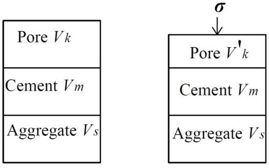
Figure 1.
Composition of concrete.
In the low stress state, the concrete displays small amounts of linear elastic deformation. According to the material mechanics, the volume of strain should be calculated by Equation (6):
where V is the volume of concrete in the unstressed state, V = Vk + Vm + Vs; V′ is the volume of concrete under stress, V′ = V′k + Vm + Vs; μ is the Poisson ratio of concrete; Ec is the elastic modulus of concrete; and σx, σy, and σz are the stress of concrete in three directions; the compressive stress is positive and the tensile stress is negative.
The relationship between the porosity of concrete and the porosity of cement paste in the unstressed state is shown in Equation (7):
where φc0 is the porosity of concrete in the unstressed state, φ0 is the porosity of cement paste in the unstressed state, Vk is the pore volume inside the concrete, and Vs is the aggregate volume inside the concrete.
Since the deformation is small, suppose V′ ≈ V. Therefore, the porosity of concrete under stress is:
Through the combination of Equations (7) and (8), the porosity of cement paste under stress is obtained as shown in Equation (9):
According to the Garboczi model and the Bentz model [33], the relationship between the diffusion coefficient of chloride ions and the porosity of cement paste is expressed by Equation (10):
where φc is critical porosity, φc = 0.18; D1 is the diffusion coefficient of chloride ions in pore solution, D1 = 2.032 × 10⁻⁹ m/s; and H(x) is a step function. If x > 0, H = 1; otherwise, H = 0.
The concrete consists of cement paste and aggregate and it is assumed that aggregate and cement paste are impermeable to each other [34]. Therefore, we assumed that the diffusion coefficient of chloride ions in aggregate is zero. The diffusion coefficient of chloride ion in concrete is calculated by:
The coefficient under the influence of stress is defined as the ratio of the diffusion coefficient under stress to the diffusion coefficient in the unstressed state.
Substituting Equation (12) into Equation (1), the equation for chloride ion transfer under the action of coupled stress-convection-diffusion was constructed and is expressed by Equation (13):
3.2. Experimental Verification
Zhang et al. [35] completed an accelerated salt spray test and the mass (m) of each component in concrete was mcement: mwater: msand: mcoarse aggregate = 1:0.53:2:3. Using plain concrete specimens in the experiment, the dimensions of the non-stressed and stressed specimens were 100 mm × 100 mm × 100 mm and 100 mm × 100 mm × 300 mm, respectively. To eliminate the influence of the confinement effect on both ends of the specimen, drilling powder was used to obtain a sample in the middle part of the specimen. After continuous spraying for 60 day in a salt spray box, the distribution of the chlorine ion mass fraction of the specimen was measured with or without stress, as shown in Figure 2. For parameter selection, we measured by experiment that fc was 28,500 kPa, C0 was 0, α was 0.2, Δx was 20 mm, and Cs was based on the test data. Through fitting the parameters of the test data in the unstressed condition, D0 and vmax were obtained. The above parameters were substituted into Equation (13) to calculate the concentration distribution of the chloride ions when the stress was 0.31fc, the experimental result is shown in Figure 2.
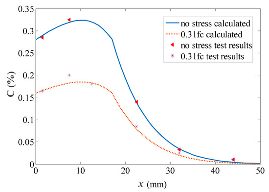
Figure 2.
Experimental data fitting.
When the stress was 0.31fc, the calculated value based on Equation (13) was consistent with the measured value. The coefficient equation under the influence of stress was determined to be suitable for the experiment.
3.3. The Stress of a Section of a Subsea Tunnel’s Lining
Take a unit along the circumferential direction of the lining ring, and set the longitudinal direction of the tunnel as the Z axis, the direction pointing to the center of the ring as the Y axis, and the direction perpendicular to the cross-section as the X axis. The normal stresses are σz, σy, and σx, respectively. Neglecting the longitudinal stress (σz = 0), the stress analysis of the tunnel lining is a plane strain problem. The lining is subjected to pressure from the surrounding rock, water, and soil; the resulting cross-section internal forces are shown in Figure 3.
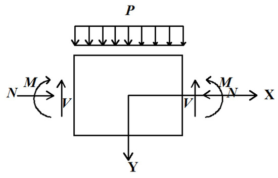
Figure 3.
The loading and inner force distribution of the tunnel lining section.
3.3.1. Normal Stresses of the Lining Section Corresponding to Bending Moment
During the normal service process, the internal forces experienced by the subsea tunnel lining are relatively small. Therefore, assuming that the concrete is in linear elasticity work, each section is consistent with the plane cross-section assumption, as shown in Figure 4.
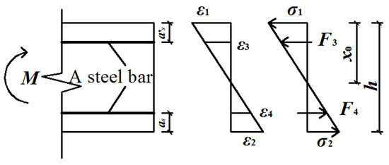
Figure 4.
The section strain and stress corresponding to bending moment.
It can be seen from the strain figure (Figure 4):
where ε1 is the strain on the edge of compression zone, ε2 is the strain on the edge of the tensile zone, ε3 is the strain of the compressive reinforcement, ε4 is the strain of the tension reinforcement, h is calculated height of the section, x0 is the height of the compression zone of the section, and as and as′ are the distance from the center of tension reinforcement and the center of compressive reinforcement to the edge of the section, respectively.
The stress or internal force at each point are shown by Equation (15):
where σ1 is the stress on the edge of the compression zone, σ2 is the stress on the edge of the tensile zone, F3 is the internal force of the compressive reinforcement, F4 is the internal force of the tension reinforcement, Es is the elastic modulus of the reinforcement, and As and As′ are sectional area of tensile reinforcement and compression reinforcement, respectively.
The static balance equations were established based on Figure 4:
where b is the width of the calculated section.
Simultaneous equations:
Among them:
where σ1 and σ2 can be obtained by substituting Equation (17) into Equation (15).
3.3.2. The Compressive Stress of the Lining Section Corresponding to the Axial Force
Under the action of axial force, the total cross-section of the lining is pressurized. The stress and strain of the lining are shown in Figure 5.
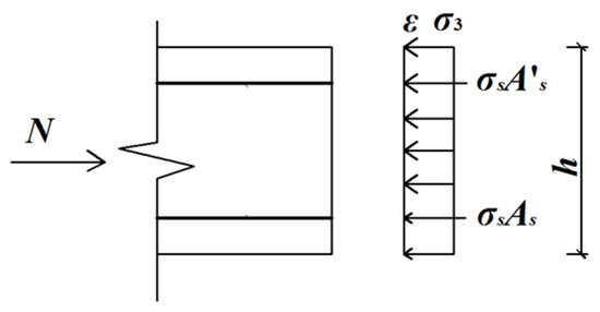
Figure 5.
The stress and strain of the section corresponding to the axial force.
The static balance equation is established based on the plane cross-section assumption:
where σ3 is the stress of concrete; σs is the stress of reinforcement; Ac is the sectional area of concrete; ε is the strain of cross section.
The compressive strain of the concrete is calculated using:
Therefore, the compressive stress of concrete is calculated by:
3.3.3. The Total Stress of the Lining Section
The total stress at the edge of the tensile stress zone or the compressive stress zone is the difference or sum of the stresses produced by M and N.
The compressive stress at the edge of the compression zone is:
The tensile stress at the edge of the tensile zone is:
If , the edge is experiencing compression; if , the edge is experiencing tension.
3.3.4. Normal Stress of the Lining Section Caused by the Surrounding Water and Soil Pressure
The normal stress of the lining section caused by the surrounding water and soil pressure point to the circle center direction. This normal stress is designated as :
where P is the total compressive force caused by the surrounding water and soil.
4. Service Life of Subsea Tunnels Based on the Reliability Theory
The corrosion of reinforcing bars is assumed to be a signal of decreased subsea tunnel durability [8]. Under the action of chloride ion erosion, when the chloride concentration in the thickness of the protective cover reaches a critical chloride ion concentration, steel corrosion starts. The corrosion of reinforcing bars in subsea tunnels is a serial system including the steel’s corrosion in the inside of the lining and the steel’s corrosion in the outside of the lining.
The durability failure probability of subsea tunnel within time T can be calculated by Equation (24):
where Ccr1 and Ccr2 are the critical concentrations of chloride ions in the inside and outside of the lining, respectively; C1 (c1,T) and C2 (c2,T) are the concentration of chloride ions in the thickness of the protective cover of the inside and outside of lining at time T, respectively, which can be obtained by Equation (13); and c1 and c2 are the thickness of the protective cover for the inside and outside of the lining, respectively.
When the reliability index in a period of time is below the objective reliability index, the service life of the lining expires. The service life Ti can be expressed by Equation (25):
where [β] is the objective reliability index corresponding to the limit of durability.
5. Engineering Application
Taking an existing subsea shield tunnel as an example, the design parameters were as follows: the outside diameter of the lining was 10.8 m, the internal diameter of the lining was 9.8 m, the width of the tunnel was 2 m, and the segment thickness was 0.5 m. For C50 concrete, its water–binder ratio (W/B) is 0.32, C0 is 0, tk is 30 years, vmax = 2 × 10⁻⁸ mm/s, Δx is 10 mm, and α is 0.70 and 0.49 on the inside and outside of the lining, respectively. It is assumed that the random parameters are relatively independent, as shown in Table 1.

Table 1.
Random parameters.
5.1. Chloride Ion Concentration Distribution
We chose the vault (maximum positive bending moment) section and the section (maximum negative bending moment) with an angle of about 45 degrees to the vault for analysis. We used the mean value of the parameters, using MATLAB software (developed by MathWorks company, US), to find the numerical solution of Equation (13) and determine the concentration distribution of the chloride ions under the action of the coupling effect at any time. The results show that the trend in the chloride ion concentration distribution in the two sections are about the same because their total cross-section are pressurized, with a comparable and smaller stress ratio (σc/fc). The stress ratio of the vault section was 0.36 and 0.22, and 0.36 and 0.23 for the section with an angle of about 45 degrees to the vault. This means that the assumptions in Section 3.1 and Section 3.3, in which the concrete is in the linear elasticity working stage, are reasonable and the derived formula is applicable. Figure 6 shows the relationship between chloride ion concentration and calculation depth, measured from the inside and outside of the lining separately, at some critical time.
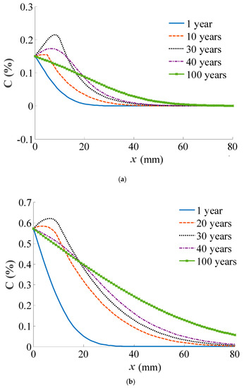
Figure 6.
The relationship between concentration of the chloride ion and the calculation depth in the (a) inside and (b) outside of the lining.
The chloride ion concentration curve can be divided into three stages according to the distribution form. In the early period, the C value decreased with the increase in calculation depth. At this point, the actual depth that chlorine ions reached by convection was small, diffusion played a dominant role. In the middle period, the C value first rose and then fell with the increase in calculation depth. When the time was 30 years, the C value reached the maximum value, and convection was about to stop (convection stopped when t = 31 years). After 31 years, only diffusion was acting. Therefore, the C value of the coupling area and its vicinity reduced gradually, and the C value of the diffusion zone increased gradually. At this stage, convection played a major role. In the late period, the effect of convection weakened, only diffusion worked, and the C value decreased with the increase in the calculation depth.
The designed service life of the tunnel is usually 100 years. Figure 7 provides a comparison of the concentration distribution of the chloride ions in the inside and outside of the lining under the coupled action and the action of diffusion alone.
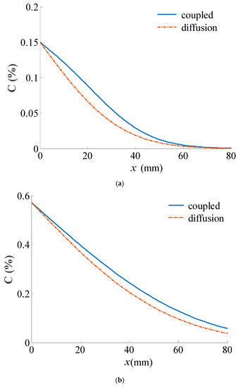
Figure 7.
The concentration distribution of the chloride ion under the coupled effect or diffusion only in the (a) inside and (b) outside of the lining.
Figure 7 shows that the C value decreases with increasing calculation depth. At any point, the C value under the coupled effect was always bigger than that of diffusion alone, showing that durability designs that do not consider the action of stress and convection are not safe.
5.2. Sensitivity of Chloride Ion Concentration Under the Coupled Effect
The chloride ion concentration at the thickness of the protective cover of the tunnel at 100 years was taken as an example to analyze the sensitivity of the parameters caused by concentration. The results are shown in Figure 8, where Δy/y is the rate of relative change in the parameters.
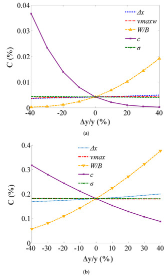
Figure 8.
Sensitivity of the concentration of the chloride ion to parameters in the (a) inside and (b) outside of the lining.
Figure 8 illustrates that the chloride ion concentration throughout the thickness of the protective cover on the inside and outside of the tunnel increased with the increase in the water–binder ratio (the diffusion coefficient), convection velocity, and the depth of the convection, and it decreased with the increase in the thickness of the protective cover and stress. The order of the concentration sensitivity in the inside of lining to each parameter is the thickness of protective cover, water-binder ratio, the depth of the convection, maximum convection velocity and stress. The order of the sensitivity of the concentration in the outside of the lining to each parameter is: water–binder ratio, the thickness of the protective cover, the depth of convection, maximum convection velocity, and stress. The most effective method of improving tunnel durability is to reduce the water–binder ratio or increase the thickness of the protective cover.
5.3. Service Life
Figure 9 shows the time-varying reliability index calculated using the Monte Carlo method: one under the coupled action of stress-convection-diffusion, and the other only considering diffusion.
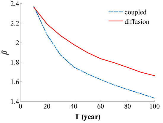
Figure 9.
The time-varying reliability index of subsea tunnel.
Figure 9 shows that the reliability index of the subsea tunnel decreased over time. The reliability index only considering the action of diffusion is larger than that considering the coupled effect of diffusion and convection. When the objective reliability index is 1.6 [36], the service life that only considers the action of diffusion is greater than 100 years, whereas the service life calculated considering the coupled effect is only 64 years, showing that the service life calculated considering stress and convection is safer.
6. Conclusions
A service life prediction method was proposed in this paper, which was validated using an existing project. The following conclusions have been drawn:
- (1)
- Under the influence of the coupled effect of diffusion and convection, diffusion played a major role in the early period, convection was the main effect during the middle period, and during the late period, diffusion was again responsible for the majority of the effect.
- (2)
- For the durability design of subsea tunnels, the coupled effect should be considered. It is safer to calculate the chloride ion concentration and predict the service life based on the coupled effect of diffusion and convection.
- (3)
- To improve the service life of subsea tunnels, the water-binder ratio should be reduced and/or the thickness of the protective cover should be increased.
- (4)
- The influence of stress on the convection was not considered, which can be studied by means of experiments and numerical simulation in future research.
Author Contributions
The first author of this paper Q.Z. developed the theoretical model and did calculations, L.L. contributed to the theoretical model and wrote the paper.
Funding
This research was supported by the Natural Scientific Research Innovation Foundation in the Harbin Institute of Technology (HIT.NSRIF. 2014133), the Research Fund for Doctoral Program of Higher Education of China (Grant No. 2016M601911), and the Natural Science Foundation of Jiangsu Province (Grant No. BK20170282). The authors gratefully appreciate the support.
Conflicts of Interest
The authors declare no conflict of interest.
References
- Eisenstein, Z.D. Large undersea tunnels and the progress of tunneling technology. Tunn. Undergr. Space Technol. 1994, 19, 283–292. [Google Scholar] [CrossRef]
- Odgard, A.; David, G.; Rostam, B.S. Design of the store belt railway tunnel. Tunn. Undergr. Space Technol. 1994, 19, 293–307. [Google Scholar] [CrossRef]
- Li, S.C.; Xu, B.S.; Li, S.C. Lining structure type of subsea tunnel and its support parameters optimizing. Chin. J. Rock Mech. Eng. 2005, 24, 3894–3902. [Google Scholar]
- Jin, W.L.; Yuan, Y.S.; Wei, J.; Wang, H.L. Design Method for the Durability of Concrete Structure under Chloride Environment; Science Press: Beijing, China, 2011. [Google Scholar]
- Bazant, Z.P. Physical model for steel corrosion in concrete sea structures-theory. J. Struct. Div. 1979, 105, 1137–1153. [Google Scholar]
- Glasser, F.P.; Marchand, J.; Samson, E. Durability of concrete-degradation phenomena involving detrimental chemical reactions. Cem. Concr. Res. 2008, 38, 226–246. [Google Scholar] [CrossRef]
- Zhang, Y.F. Study on the Durability Evaluation of Lining Structure in Sea Area during Subway Operation Period. Master’s Thesis, Beijing Jiaotong University, Beijing, China, 2018. [Google Scholar]
- Zhao, T.J.; Jiang, F.X. Durability of Subsea Tunnels; China Communications Press: Beijing, China, 2010. [Google Scholar]
- Jin, Z.; Zhao, T.; Hou, B. Service Life Prediction of Lining Concrete for Jiaozhou Bay Subsea Tunnel. Archit. Environ. Eng. 2009, 31, 86–91. [Google Scholar]
- Qu, L.; Jin, Z.; Zhao, T.; Li, Q. Study on durability parameter design of subsea tunnel reinforced concrete based on chloride corrosion. Chin. J. Rock Mech. Eng. 2007, 26, 2333–2340. [Google Scholar]
- DuraCrete. Chloride ingress initiation of corrosion. In General Guidelines for Durability Design and Redesign; Probabilistic Performance Based Durability Design of Concrete Structure; CUR: Gouda, The Netherlands, 2000; pp. 32–38. [Google Scholar]
- Yang, L. Investigation of Moisture and Chloride Ion Transport Inunsaturated Concrete. Ph.D. Thesis, Southeast University, Nanjing, China, 2017. [Google Scholar]
- Zhang, Y.; Li, X.; Yu, G. Chloride transport in undersea concrete tunnel. Adv. Mater. Sci. Eng. 2016, 2016, 1–10. [Google Scholar] [CrossRef]
- Liu, S.; Sun, Q.; Feng, K.; He, C. Research on chloride ion erosion and migration in segment joints of undersea shield tunnels. Mod. Tunn. Technol. 2016, 53, 100–107. [Google Scholar]
- Liu, Q.; Huang, M.; Jin, F. Study on durability and service life of concrete structure of coastal tunnel. J. Beijing Jiaotong Univ. 2018, 42, 1–8. [Google Scholar]
- Lei, M.F. Research on Calculation Methods of Life-Cycle Structure Performance of Shield Tunnel in Aggressive Environment. Ph.D. Thesis, Central South University, Changsha, China, 2013. [Google Scholar]
- Liu, S.; He, C.; Feng, K.; An, Z. Research on corrosion deterioration and failure process of shield tunnel segments under loads. China Civ. Eng. J. 2018, 51, 120–128. [Google Scholar]
- Song, Y.S. Study on Shield Segment Concrete Durability of Resistance to Chloride Ion and Service Life Prediction. Master’s Thesis, Beijing Jiaotong University, Beijing, China, 2015. [Google Scholar]
- Fang, S. The Reliability Analysis Based on Durability Performance Degradation about the Existing Tunnel Lining Structure. Master’s Thesis, Shijiazhuang tiedao University, Shijiazhuang, China, 2018. [Google Scholar]
- Li, Q.; Yu, H.F.; Ma, H.Y.; Chen, S.D.; Liu, S.G. Test on Durability of Shield Tunnel Concrete Segment under Coupling Multi-Factors. Open Civ. Eng. J. 2014, 8, 451–457. [Google Scholar] [CrossRef]
- Yue, Z.W.; Li, J.P.; Yang, B. Calculation of chloride ions transportation in concrete considering convection. J. Tongji Univ. Nat. Sci. 2015, 43, 60–66. [Google Scholar]
- Bentz, E.C.; Thomas, M.D.A. Computer program for prediction the service life and life-cycle costs of reinforced concrete exposed to chlorides. In Life-365 Manual; SFA: Edison, NJ, USA, 2013. [Google Scholar]
- Zhao, Q.L.; Zhang, Y.Z. Concentration distribution of chloride ion under the influence of the convection-diffusion coupling. Adv. Mater. Sci. Eng. 2017, 2017, 207698. [Google Scholar] [CrossRef]
- Liu, L.; Chen, H.; Sun, W.; Ye, G. Microstructure-based modeling of the diffusivity of cement paste with micro-cracks. Constr. Build. Mater. 2013, 38, 1107–1116. [Google Scholar] [CrossRef]
- Hoseini, M.; Bindiganavile, V.; Banthia, N. The effect of mechanical stress on permeability of concrete: A review. Cem. Concr. Compos. 2009, 31, 213–220. [Google Scholar] [CrossRef]
- Djerbi, T.A.; Bonnet, S.; Khelidj, A.; Baroghel-Bouny, V. Effect of uniaxial compressive loading on gas permeability and chloride diffusion coefficient of concrete and their relationship. Cem. Concr. Res. 2013, 52, 131–139. [Google Scholar] [CrossRef]
- Choinska, M.; Khelidj, A.; Chatzigeorgiou, G.; Pijaudier-Cabot, G. Effects and interactions of temperature and stress-level related damage on permeability of concrete. Cem. Concr. Res. 2007, 37, 79–88. [Google Scholar] [CrossRef]
- Luo, D.; Niu, D.; Su, L. Research progress on durability of stressed concrete under environmental actions. Eng. Mech. 2019, 36, 1–14. [Google Scholar]
- Dong, J. Cracking and Spalling of Reinforced Concrete Structures under Simultaneous Loading and Chloride Penetration. Ph.D. Thesis, Zhejiang University, Hangzhou, China, 2018. [Google Scholar]
- Jin, L.; Zhang, R.B.; Du, X.L. Multi-scale analysis for the chloride diffusivity in concrete subjected to low-level stress. Eng. Mech. 2017, 34, 84–92. [Google Scholar]
- Bernard, F.; Kamali-Bernard, S. Numerical study of ITZ contribution on mechanical behavior and diffusivity of mortars. Comput. Mater. Sci. 2015, 102, 250–257. [Google Scholar] [CrossRef]
- Du, X.; Jin, L.; Zhang, R. Chloride diffusivity in saturated cement paste subjected to external mechanical loadings. Ocean Eng. 2015, 95, 1–10. [Google Scholar] [CrossRef]
- Bentz, D.P.; Garboczi, E.J. Percolation of phases in a three-dimensional cement paste microstructure modal. Cem. Concr. Res. 1991, 21, 325–344. [Google Scholar] [CrossRef]
- Du, X.; Jin, L.; Ma, G. A meso-scale numerical method for the simulation of chloride diffusivity in concrete. Finite Elem. Anal. Des. 2014, 85, 87–100. [Google Scholar] [CrossRef]
- Zhang, W.P.; Zhang, Q.Z.; Gu, X.L.; Zhong, L.J.; Huang, Q.H. Effects of environmental conditions and stress level on chloride ion transport in concrete. J. Jiangsu Univ. Nat. Sci. Ed. 2013, 34, 101–106. [Google Scholar]
- Siemes, A.J.M.; Rostam, S. Durable Safety and Serviceability—A Performance Based Design Format. Basis of Design and Actions on Structures-Background and Application of Eurocode 1. IABSE Report 74. In Proceedings of the IABSE Colloquium, Delft, The Netherlands, 27–29 March 1996. [Google Scholar]


© 2019 by the authors. Licensee MDPI, Basel, Switzerland. This article is an open access article distributed under the terms and conditions of the Creative Commons Attribution (CC BY) license (http://creativecommons.org/licenses/by/4.0/).