Abstract
This work presents the results of the overall design of the first Italian roundabout with jointed plain concrete pavement. The examined case study complies with current international standards and practices for geometry of roundabouts and road pavements. The construction of a concrete pavement in an urban roundabout will better manage and slow down fast vehicular flows, and increase traffic fluidity in an important junction, trafficked by heavy vehicles, where maintenance works should be reduced to avoid queues. The design of the roundabout involved several competences for: defining the geometry of the four-arm junction, designing the thickness of the jointed plain concrete pavement both on the circular crown and the arms, studying the mix design of a high resistance concrete. As regard to the pavement, the result of the study was an un-dowelled concrete pavement composed of square slabs laid on a cement concrete subbase and a granular layer. The shape of the slabs has been designed to optimize the structural performance of their material, which is a high strength concrete mix derived from an extensive laboratory test work. In general, the results summarized approaches typical of different design conditions: urban ones for traffic flow and safety needs; high-traffic ones for the chosen pavement type; airport ones for the absence of dowel and tie bars at the joints. Indeed, the article has highlighted that the design process of a concrete roundabout requires multiple analyses to consider various features and correctly re-design an existing urban junction. Its geometrical design, the structural design of the concrete pavement and the theoretical and experimental design of the concrete mix were the main phases of this process and they needed different competences to conduct comprehensive and appropriate analyses.
1. Introduction
Roundabout is a road junction composed of an unsurmountable central island, around which vehicles circulate counter-clockwise in the Countries where the regulation is right-hand traffic. The solution enables the collection and distribution of all vehicles that access and egress the intersection, from the different arms, on the same trajectory.
Roundabouts are usually built to increase traffic fluidity or to manage and slow down fast vehicular flow [1]. In the first case they can be located at intersections with high traffic volumes; in the second case they replace quiet residential junctions, in the form of miniroundabouts, to make intersections safer for pedestrians, and vulnerable users in general [2,3,4]. The roundabouts can as well cut down vehicular emissions and fuel consumption by reducing the vehicle idle time at intersections and thereby creating a positive impact on the environment [5,6,7].
A remarkable advantage of roundabouts is increasing safety for vehicles using the intersection by reducing the fatal crashes and all crashes by a significant percentage [8,9]. In the USA a study on 23 intersections estimated highly significant reductions of 40% for all crash severities combined and 80% for all injury crashes [10]. Similar reductions were found in some studied performed all over Europe [11,12].
The design process of a roundabout requires the definition of its geometric characteristics according to the expected traffic demand and the layouts defined by the reference standards. There are many ways to classify a roundabout: according to the yield pattern, its approach lanes, design speed, etc.
The typology proposed by the U.S. Federal Highway Administration (FHWA) [13] is maybe the most complete, since it is based on the statement that “a roundabout is a type of a circular intersection, but not all circular intersections can be classified as roundabouts”. FHWA detects the following types of circular intersection:
- Roundabouts: circular intersections with specific features as yield control of entering traffic, channelized approaches, appropriate geometric curvature;
- Rotaries: old-style circular intersections, typical of USA roads up to the ’60 s, with a large diameter (even > 100 m), and where circulating traffic yields to entering traffic;
- Signalized traffic circle: old-style circular intersections, used in some cities of the USA where traffic signals are used to control one or more entry-circulating point.
- Neighborhood traffic circles at intersections of local streets for traffic calming or “aesthetics” reasons.
FHWA separates the roundabouts into three basic categories according to size and number of lanes:
- (1)
- Mini roundabouts: small roundabouts in low speed urban areas with average operating speed of 50 km/h or less, useful in environments with right of way constraints or with insufficient right of way for compact roundabouts
- (2)
- Single-lane roundabouts: they have a single lane entry at all arms and around the central island, they have larger inscribed circle diameters than the mini roundabout and non-traversable central area; higher vehicular capacity and consistent entering and exiting speeds (30 to 40 km/h) are important features of this kind of roundabout.
- (3)
- Multilane roundabouts: they are characterized by two or more entry lanes at least on one approach with an entry speed of 40–50 km/h and by wider circulatory roadways.
In 1997, the Roundabouts Swiss Guide [14], considered three types of roundabout, according to size, to environment of application and to limitations of maneuvers: big roundabouts, compact roundabouts, and mini roundabouts (with semi/fully mountable island). But later on, according to Swiss Standard SN 640263 [15], roundabouts were classified into just two categories, according to their external diameter and configuration: the compact ones (for high traffic environments, external diameter between 26 and 40 m, not mountable central island) and the mini ones (for local traffic, external diameter between 14 and 26 m, mountable or semi mountable central island). Mini roundabouts are recommended to be avoided in case of high pedestrian traffic.
CERTU’s (Centre d’études sur les réseaux, les transports, l’urbanisme et les constructions publiques) French recommendations are basically in accordance to what stated in the Swiss regulation (big/compact and mini roundabouts) with slight differences for what concerns the related size [16]; also, in this case, pedestrian crossings are recommended on the arms, taking care to locate them at a suitable distance from the “give the right” sign (not farther than 2–5 m).
Italian standards on roundabouts define three kinds of roundabouts [17]:
- the so-called “conventional” ones (i.e., big roundabouts with arms with the same width up to the accessing point), with an external diameter between 40 and 50 m;
- the compact ones (with a smaller diameter in comparison to the conventional ones and with arms with enlargements at the accessing points) with an external diameter between 25 and 40 m;
- the mini roundabouts, with an external diameter between 14 and 25 m.
The same approach can be found in standards from other countries; in Norway, for instance, classification pattern is very similar to the other European cases, assuming as main criteria the diameter of the central island and the inscribed circle diameter [18]. They lead to classify roundabouts into large, medium, small and mini [19,20,21].
The geometrical design of the roundabout here presented is compliant with the Italian standard, as requested by the local government of the region in which the junction is located. At any rate, they are very similar to those required in other countries.
Table 1 summarizes the main characteristics of roundabouts according to Italian standards.

Table 1.
Characteristics of roundabouts according to the Italian standards.
Even if the geometrical details of the roundabout are defined according to the national standards, the dimensions (truck apron, roadway widths, curvature, etc.) are generally verified by a swept path analysis. Many studies are available on this subject [22,23,24], generally performed by means of specialist software. In this case, the design of the roundabout has been verified graphically conducting the swept path analysis according to the constant pursuit method [25]. The design vehicle was a tractor trailer 2.2 m wide and 16 m long with 4 axles.
The type and the sizes of the roundabouts vary according to vehicles flow, even when, as in the case of mini roundabouts, they can be implemented in sites where pedestrian traffic can become dominant.
In conclusion, roundabouts differ from other circular intersections because of the following features: traffic control (yield control on all entries); priority to circulating vehicles (they have the right-of-way); pedestrian accesses (only across the arms of the roundabouts); no parking allowed; counter-clockwise circulation on the ring [26]. On the contrary, stop control or no control at all can occur on traffic circles, circulating traffic can be required to yield to entering traffic, pedestrians can cross through to access to the central island, parking can be allowed.
The aim of this paper is to present the overall design process of a compact roundabout to be built in the Southern Italy, in the Municipality of Soleto. The roundabout will be the first one in Italy with a jointed plain concrete pavement, and will serve heavy traffic from and to a cement factory. The choice of a concrete pavement is justified by the lower maintenance required than an equivalent bituminous pavement [27,28]. The proposed study involves traffic analysis, geometric design of the intersection, calculation of the pavement thickness, design of joint layout, and laboratory tests to define the concrete mix. The importance of this work is that it provides information about the whole process needed to transform an existent ordinary four-arm junction into a compact roundabout, according to the regulatory reference above-mentioned. The value of these analyses is that the results are useful to identify and improve processes and technologies currently used in this field in order to optimize traffic performance at intersections.
2. Design Process
The intersection to re-design is represented in Figure 1; currently, it is an ordinary grade four-arm junction.
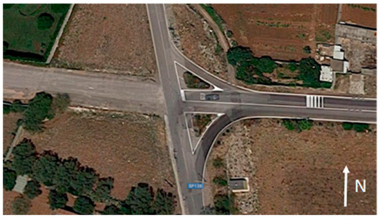
Figure 1.
The intersection to redesign (photo: Google maps).
In the last years, there was an increase of accidents on the North-South alignment [29] due to:
- the high speed induced by the road planimetric alignment (i.e., straight and horizontal slope);
- the incorrect perception of the transition between the rural and urban context (the urban environment starts at the intersection).
In addition, due to high levels of heavy traffic running on the intersection, the local authority decided to convert it into a medium compact roundabout as a traffic calming solution [30].
Also, from the economic point of view, a roundabout represents a good solution: in a previous study [7] two separate economic analyses were developed to compare a roundabout and an intersection at grade: the first on fuel consumption, and the second including also the average delay experienced by users. The analyses highlighted that after few years (less than five), the construction costs spent in roundabouts are refunded, for the common good, by benefits on users [31].
The design of the intersection consists of the following steps:
- traffic analysis;
- design of geometric layout of the roundabout;
- design of the thickness pavement;
- design of the joint layout;
- mix design of concrete.
2.1. Traffic Analysis
This type of traffic requires specific and accurate analyses of the traffic demand to serve, which affects the design of the appropriate geometric and structural features, and its control, to ensure regular and safe flows at road intersections. The demand analysis required a survey of traffic flows, to collect data on traffic volume and components. Each type of vehicle surveyed was classified by means of a traffic monitoring system. Traffic was surveyed for longer periods in the daytime. Monitoring (point P in Figure 2) involved both directions of the busiest arm, thus highlighting where highest traffic flows can be located (red in Figure 2).
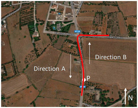
Figure 2.
Monitored traffic scenario (photo: Google maps).
Table 2 reports data collected during early morning time.

Table 2.
Observed vehicles in both directions.
The observed traffic volume of the vehicles from all the arms does not exceed 500 vehicles/h, therefore according to Brilon [32] there is no need for evaluation of traffic capacity of the one-lane roundabout.
The analysis of traffic composition highlighted that volume of motorcycles is negligible, whereas heavy vehicles account for an average 15% of the total volume of passenger cars and heavy vehicles (Figure 3 and Figure 4). More specifically, heavy vehicles were 21% and 12% of total traffic respectively for directions A and B represented in Figure 2.
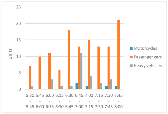
Figure 3.
Vehicles in direction A.
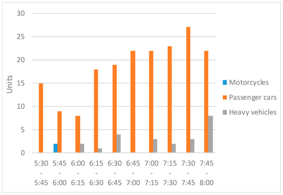
Figure 4.
Vehicles in direction B.
2.2. Geometric Layout of the Roundabout
The survey reported flows of single unit or single trailer trucks, which required the study of their swept path envelopes, the larger of which due to 18 m long and 2.55 m wide vehicles. Moreover, the geometric configuration of the current junction and its comparison with the project (Figure 5a), its surrounding not-built area were additional constraints considered to design the counterclockwise roundabout (Figure 5b), according to the Italian standard for road intersection design [17].
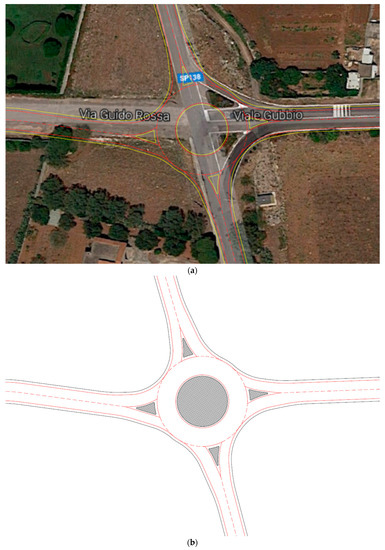
Figure 5.
(a) Superimposition of the design on raster map (photo: Google maps) (b) Geometric design of the roundabout.
According to the Italian standards for road intersection, the geometric requirements to be met by the following design criteria were [17]:
- for each arm, deviation angle ≥45°;
- number of entry lanes = 1;
- approach width lane equal to 3.5 m;
- exit width lane equal to 4.5 m;
- number of circulating lanes = 1;
- circulating road width composed of the lane and the lateral shoulders equal to 8.5 m;
- unsurmountable central island.
2.3. Thickness of Road Pavement
Meeting all the above requirements enables to accommodate any type of vehicles, according to the survey information. They have load limits of 44 t with no more than 5 axles with a maximum axle weight limit of 12 t (Table 3). 9 heavy vehicle types have been considered, they have single (S), tandem, or tridem axles with single (s) or twin (t) wheels [33].

Table 3.
Considered heavy vehicles.
The flows of the different types of heavy vehicles in percentage (Table 2), the yearly traffic volume and the service life have been considered as design inputs for designing road pavement. The yearly traffic volume and the service life were considered as inputs to design the road pavement. Data collected during the traffic surveys (partially shown in Figure 3 and Figure 4) allowed the estimation of the cumulated yearly traffic level. To this aim peak time values determined the design-hourly volume (DHV). For the direction A, DHV is equal to 26 heavy vehicles in 2.5 h. As more than 95% of traffic volume at the junction is generated by the nearby cement plant, the following referencing parameters were considered for the calculation of the Total number of Yearly Passages (TYP):
- 12 h a day (H);
- 6 days a week (D);
- 47 weeks per year (W),
Thus resulting in Equation (1):
TYP = DHV × H × D × W = 35,000 units,
Therefore, at the end of project life of 20 years, the number of commercial vehicle passages is 700,000 (Equation (2)), assuming equal to 0 the traffic growth rate. Such assumption relies on the forecast of no changes in the cement plant operations, nor in the local land use, which enables to forecast:
where
TP = TYP × Y = 700,000 units,
- TP: number of commercial vehicle passages
- TYP: Total number of Yearly Passages
- Y: project life

Table 4.
Total number of passages of each heavy vehicle type.
A Jointed Plain Concrete Pavement (JPCP) has been then designed: it is the first experience of road concrete pavement in Italy for a roundabout. Therefore, it represents an important novelty in a State where road concrete pavements are not currently used in nigh on 30 years [34] and only recently JPCPs are used to pave road tunnels [35] due to their technical and economic advantages if compared to asphalt pavements [36,37].
This type of pavement has a high strength to the tangential stresses that the heavy traffic produces during its motion along the curve. In addition, the pavement of this roundabout is subjected to a high traffic volume at low speed that can produce high level of rutting in materials like the asphalt concrete [38].
These are the main reasons for the choice of concrete pavements: recent studies demonstrated the economic convenience on the life cycle of rigid pavements compared to asphalt pavements when maintenance costs are considered [27].
The thickness design of JPCP was designed with the Westergaard theory, which permits to calculate the stresses induced in the slabs by traffic loads [39].
This rational theory gives theoretical closed-form solutions for concrete slabs. They are based on the theory of thin slabs, with the slab’s transverse dimension, or thickness, small if compared to the length and width dimensions. A fatigue verification of concrete has been calculated according to the Miner’s law (Equation (3)).
where n is the number of load repetitions during the design life and N is the number of allowable load repetitions. N was calculated with the experimental law proposed by Sawan–Darter (Equation (4)) [33]
Finally, the pavement has been verified according to the AASHTO (American Association of State Highway and Transportation Officials) Guide method [40].
The AASHTO method is based on the comparison between the forecast number of repetition of traffic loads (N18) over the pavement life and the performance of pavement layers (W18). Both N18 and W18 are calculated considering an Equivalent Single Axle Load (ESAL) whose weight is 81.6 kN.
For each axle listed in Table 2, W18 has been calculated according to Equation (5).
where ZR is the standard normal deviate, So is the combined standard error of the traffic prediction and performance prediction; D is the slab thickness; ΔPSI is the difference between the initial and final PSI, which measures the ability of the pavement to serve the design traffic; S’c is the modulus of rupture of concrete; J is the load transfer efficiency between adjacent slabs; Cd is the drainage coefficient; Ec is the Young modulus of concrete; K is the subgrade modulus of reaction.
Table 5 lists the values of variables of Equation (5).

Table 5.
Input data for pavement design.
By applying data from Table 4, W18 is equal to 2.64 million.
The expected ESAL N18 is the sum of the ESALs (Nx) calculated for each combination of load, axle, and wheel (x) listed in Table 2. Equation (6) allowed the calculation:
where Lx is the load on one single axle, one set of tandem axles or one set of tridem axles; L2 depends on the axle type (1 for single axle, 2 for tandem axles, 3 for tridem axles); Gt and βx are respectively calculated according to Equations (7) and (8).
Table 6 lists the data for calculation of N18: the sum of values listed in column N18,x is equal to N18.

Table 6.
Data for calculation of N18.
N18 is equal to 1.61. Therefore, the condition in Equation (9):
is satisfied and the pavement is verified.
In conclusion, the concrete pavement of the circulatory roadway is composed of un-dowelled 27 cm thick concrete slabs cast in situ over a 15-cm thick cement bound layer and 15 cm thick granular layer. Figure 6 represents the pavement layers.
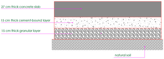
Figure 6.
Pavement section.
Despite the low number of heavy vehicle passages, the thickness of the slabs is quite remarkable, due to the high value of the weight of the vehicles coming from the cement plant. Indeed, the concrete slab thickness is more sensitive to the weight than to than to the stress repetitions [41].
The 8.5 m wide section is composed of one 7 m wide circulating lane, and an outside 1.00 m wide shoulder, and an inside 0.50 m wide shoulder (Figure 7), as required by the Italian standards. The concrete layer will be 9.00 m wide, to avoid severe loading conditions transmitted by the long vehicles running close to the central island.

Figure 7.
Cross section of circulatory roadway (unit of measure: m).
2.4. Joint Layout
The geometric joint layout defined for the roundabout crown is a radial-type, as represented in Figure 8. Thick lines represent construction and isolation joints.
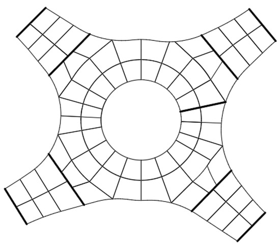
Figure 8.
Joint layout.
The joint layout has been defined to obtain regular and “square” as much as possible slabs. 18 slabs have been designed along two concentric circular crowns: each slab is a sector of the circular crown with an average 20° central angle and an average 4.5 m width [42].
Two types of joints have been designed: contraction and isolation joints according to Figure 8. The low radius of curvature prevented the use of dowel and tie bars, which are currently used in JPCP. Indeed, in such conditions, vehicles trajectories are not regularly channeled [43] as it happens in other conditions (i.e., straight or ordinary curved track of the alignment): this means that it is impossible to put correctly the steel reinforcement, as usually it happens for airport JPCPs [44]. Moreover, an incorrect position of bars could induce severe stresses and cause the premature failure of the pavement.
Planimetric curvature of the circulatory roadway pavement involves variable length of slabs: for the inner crown, the internal side of the slabs is 3.8 m long, while for the outer crown the external side of the slabs is 5.45 m. Nevertheless, the slabs are “square”, as recommended by the Roads and Traffic Authority [38]. Indeed, their shape factor calculated according to Equation (10) is less than 1.25 (1.18 and 1.21 respectively for the inner and outer crowns):
where L and W are respectively the length and the width of the slabs.
Moreover, the ratio between the average dimension (4.5 m) and the thickness of the slabs is 16: less than 25, the higher value recommended by PIARC (World Road Association) [42].
As regard as the joint layout of arms, slabs are, whenever possible, square. The lower limit of slab width is 1.0 m in trafficked areas and 0.60 m in those with lower traffic volumes: this solution prevents slabs from rapidly deteriorating as consequence of high deflections.
2.5. Mix Design of Concrete
Mix design of concrete had several minimum goals. Table 7 lists them.

Table 7.
Physic and mechanical minimum properties of concrete.
Laboratory tests (i.e., compressive and indirect tensile strength tests) carried out to define the concrete mix gave the results listed in Table 8.

Table 8.
Physic and mechanical properties of the designed concrete mix.
Mechanical properties of concrete are very important: the cement content is high to satisfy the laid down requirement about the minimum value of modulus of rupture. Therefore, its characteristic cubic resistance at 28 days is over than 58 MPa: the mix is a high strength concrete according to the European standard EN 206-1 [45].
The cement concrete will be carried on trucks from the concrete plant and the roundabout pavement will be placed with a manual method. It will be finished by vibration, cured, and brushed to improve the friction between tire and pavement. During the construction phase, the best evaluation methods for improving surface geometry of concrete slabs of pavement will be adopted [46]. At the end, a more sustainable decision-making process will require tools for analyzing the economic, environmental, and social impacts, as well as for comparing the pavement investment trade-offs considering the next phase of management [47].
3. Conclusions
This paper presents the overall design process of the first Italian roundabout with jointed plain concrete pavement. As a result, a compact roundabout will substitute an existing ordinary four-arm intersection. The adopted design methods about geometry and materials comply with current international standards. The concrete pavement has been designed according to the AASHTO Guide 1993 considering the traffic spectrum defined by the Italian standards. The thickness was verified with the theory of Westergaard and the fatigue law. The layout of pavement joints was specifically targeted to obtain regular and “square” as much as possible slabs both in the circular crown and in the arms. The study of mix design carried out the definition of a high strength concrete to meet the mechanical requirements. The results evidenced that the process requires multiple analyses to consider various features and correctly re-design the junction. In conclusion, the study involved three main steps:
- the geometrical design of the junction, as a compact roundabout;
- the structural design of the concrete pavement;
- the theoretical and experimental design of the concrete mix.
As observed in this study, the contribution of each phase to the overall design process plays a different role, demonstrating the need for involving different competences to conduct comprehensive and appropriate analyses.
Author Contributions
Maria Vittoria Corazza and Giuseppe Loprencipe designed the junction; Giovanni Vincenti and Sergio Vivaldi conceived and designed the experiments on concrete; Paola Di Mascio and Laura Moretti designed the pavement; all the authors wrote the paper.
Conflicts of Interest
The authors declare no conflict of interest.
References
- Macioszek, E. Relationship between Vehicle Stream in the Circular Roadway of a One-Lane Roundabout and Traffic Volume on the Roundabout at Peak Hour. Commun. Comput. Inf. Sci. 2014, 471, 110–119. [Google Scholar]
- Corazza, M.V.; Di Mascio, P. How to make traffic calming more walking friendly: Directions to increase intersections performances for pedestrians. In Proceedings of the Extra Workshop ICTCT—Safe Non-Motorised Traffic, Planning, Evaluation, Behavioural, Legal and Institutional Issues, Vancouver, BC, Canada, 5–6 January 2003. [Google Scholar]
- Corazza, M.V.; Di Mascio, P.; Moretti, L. Managing sidewalk pavement maintenance: A case study to increase pedestrian safety. JTTE 2016, 3, 203–214. [Google Scholar] [CrossRef]
- Corazza, M.V.; Di Mascio, P.; Moretti, L. Management of sidewalk maintenance to improve walking comfort for senior Citizens. WIT Trans. Built Environ. 2017, 176, 195–206. [Google Scholar] [CrossRef]
- Miccoli, S.; Finucci, F.; Murro, R. A new generation of urban areas: Feasibility elements. In Proceedings of the International Conference on Energy Equipment Science and Engineering, Guangzhou, China, 30–31 May 2015; Volume 2, pp. 1445–1450. [Google Scholar]
- Mandavilli, S.; Rys, M.J.; Russell, E.R. Environmental impact of modern roundabouts. Int. J. Ind. Ergon. 2008, 38, 135–142. [Google Scholar] [CrossRef]
- Cantisani, G.; Loprencipe, G.; Primieri, F. The integrated design of urban road intersections: A case study. In Proceedings of the ICSDC 2011: Integrating Sustainability Practices in the Construction Industry, Kansas City, MO, USA, 23–25 March 2012; pp. 722–728. [Google Scholar]
- Persia, L.; Usami, D.S.; De Simone, F.; Beaumelle, V.F.D.L.; Yannis, G.; Laiou, A.; Han, S.; Machata, K.; Pennisi, L.; Marchesini, P.; et al. Management of Road Infrastructure Safety. Transp. Res. Procedia 2016, 14, 3436–3445. [Google Scholar] [CrossRef]
- Persia, L.; Gigli, R.; Usami, D.S. Smeed’s law and expected road fatality reduction: An assessment of the Italian case. J. Saf. Res. 2015, 55, 121–133. [Google Scholar] [CrossRef] [PubMed]
- Persaud, B.; Retting, R.; Garder, P.; Lord, D. Safety Effect of Roundabout Conversions in the United States: Empirical Bayes Observational Before-After Study. Transp. Res. Rec. 2001, 1–8. [Google Scholar] [CrossRef]
- Hydén, C.; Várhelyi, A. The effects on safety, time consumption and environment of large scale use of roundabouts in an urban area: A case study. Accid. Anal. Prev. 2000, 32, 11–23. [Google Scholar] [CrossRef]
- Elvik, R. Effects on Road Safety of Converting Intersections to Roundabouts Review of Evidence from Non-U.S. Studies. Transp. Res. Rec. 2003, 1847, 1–10. [Google Scholar] [CrossRef]
- Rodegerdts, L.; Bansen, J.; Tiesler, C.; Knudsen, J.; Myers, E.; Johnson, M.; Moule, M.; Persaud, B.; Lyon, C.; Hallmark, S.; et al. NCHRP Report 672: Roundabouts: An Informational Guide, 2nd ed.; Transportation Research Board: Washington, DC, USA, 2010. [Google Scholar]
- École Polytechnique Fédérale de Lausanne (EPFL). Guide Suisse des Giratoires, Cahier TEA n.10; Department de Genie Civil: Lausanne, Switzerland, 1997. [Google Scholar]
- Norme Suisse. SN 640263 Carrefours Giratoires; VSS: Zurich, Switzerland, 2000. [Google Scholar]
- Centre D’études sur les Réseaux, les Transports, l’urbanisme et les Constructions Publiques (CERTU). Guide Carrefours Urbains; Chapter 9; Les Guratoires: Lyon, France, 1999. [Google Scholar]
- Ministero delle Infrastrutture e dei Trasporti. Norme Funzionali e Geometriche per la Costruzione Delle Intersezioni Stradali; Italian Ministry of Transportation Decreto Ministeriale: Rome, Italy, 2006.
- Seim, K. Use, design and safety of small roundabouts in Norway. In Intersections without Traffic Signals II; Brilon, W., Ed.; Springer: Berlin/Heidelberg, Germany, 1991; Available online: https://doi.org/10.1007/978-3-642-84537-6_19 (accessed on 21 December 2017).
- Botma, H. State of the art of roundabouts in the Netherlands. In Proceedings of the 3th International Symposium on Intersections without Traffic Signals, Portland, OR, USA, 21–23 July 1997; National Research Council: Washington, DC, USA, 1997; pp. 55–60. [Google Scholar]
- Forschungsgesellschaft für Straßen- und Verkehrswesen (FGSV). Merkblatt für die Anlage von Kreisverkehren; FGSV Verlag GmbH: Köln, Germany, 2006. [Google Scholar]
- Ministry of Transport. Roundabouts—Application and Design: A Practical Manual; Ministry of Transport, Public Works and Water Management: Amsterdam, The Netherlands, 2009.
- Godavarthy, R.; Russell, E.; Landman, D. Using vehicle simulations to understand strategies for accommodating oversize, overweight vehicles at roundabouts. Transp. Res. Part A 2016, 87, 41–50. [Google Scholar] [CrossRef]
- Russell, E.R.; Landman, E.; Godavarthy, R. Accommodating Oversize/Overweight Vehicles at Roundabouts; Report No. K-TRAN: KSU-10-1; Kansas Department of Transportation: Topeka, KS, USA, 2013.
- Godavarthy, R.; Russell, E. Integrating Roundabouts with Freight Roadway Networks. Smart Grid Renew. Energy 2015, 6, 293–302. [Google Scholar] [CrossRef]
- Joel, P.; Leisch, P.; Milton Carrasco, P. Design Vehicles: From Turning Templates to Smart Systems. Transportation Association of Canada Conference, Montreal, Quebec, Canada. 2014. Available online: http://conf.tac-atc.ca/english/annualconference/tac2014/s-30/leisch.pdf (accessed on 12 November 2017).
- Tollazzi, T.; Mauro, R.; Guerrieri, M.; Rencelj, M. Comparative analysis of four new alternative types of roundabouts: “Turbo”, “flower”, “target” and “four-flyover” roundabout. Period. Polytech. Civ. Eng. 2016, 60, 51–60. [Google Scholar] [CrossRef]
- Moretti, L.; Di Mascio, P.; Panunzi, F. Economic Sustainability of Concrete Pavements. Procedia Soc. Behav. Sci. 2012, 53, 125–133. [Google Scholar] [CrossRef]
- Moretti, L. Technical and Economic Sustainability of Concrete Pavements. Mod. Appl. Sci. 2014, 8. [Google Scholar] [CrossRef]
- Automobile Club d’Italia (ACI). Road Accidents in Italy; ACI: Rome, Italy, 2017. [Google Scholar]
- Bunn, F.; Collier, T.; Frost, C.; Ker, K.; Roberts, I.; Wentz, R. Traffic calming for the prevention of road traffic injuries: Systematic review and meta-analysis. Inj. Prev. 2003, 9, 200–204. [Google Scholar] [CrossRef] [PubMed]
- Miccoli, S.; Finucci, F.; Murro, R. Measuring Shared Social Appreciation of Community Goods: An Experiment for the East Elevated Expressway of Rome. Sustainability 2015, 7, 15194–15218. [Google Scholar] [CrossRef]
- Brilon, W. Experiences with Modern Roundabouts in Germany—A State of the Art Report; Ruhr-University Bochum, Institute for Transportation and Traffic Engineering: Athens, Greece, 2011. [Google Scholar]
- Consiglio Nazionale delle Ricerche (CNR). Catalogo delle Pavimentazioni Stradali; Bollettino Ufficiale 178/95; CNR: Rome, Italy, 1995. [Google Scholar]
- Federbeton. Strade Concrete per la Rigenerazione Urbana; Concrete Roads for Urban Regeneration; Studio Associato Comunicarch: Torino, Italy, 2014. [Google Scholar]
- International Society for Concrete Pavements. Industry News, Resources & Webinars; International Society for Concrete Pavements: Washington, DC, USA, 2014; Volume 11, Number 3. [Google Scholar]
- Moretti, L.; Cantisani, G.; Di Mascio, P. Management of road tunnels: Construction, maintenance and lighting costs. Tunn. Undergr. Space Technol. 2016, 51, 84–89. [Google Scholar] [CrossRef]
- Moretti, L.; Cantisani, G.; Di Mascio, P.; Caro, S. Technical and economic evaluation of lighting and pavement in Italian road tunnels. Tunn. Undergr. Space Technol. 2017, 65, 42–52. [Google Scholar] [CrossRef]
- Roads and Traffic Authority. Concrete Roundabout Pavements: A Guide to Their Design and Construction; Roads and Traffic Authority: Sydney, Australia, 2004.
- Westergaard, H.M. Stresses in concrete pavements computed by Theoretical Analysis. Public Roads 1926, 7, 25–35. [Google Scholar]
- American Association of State Highway and Transportation Officials (AASHTO). Guide for Design of Pavement Structures; American Association of State Highway and Transportation Officials: Washington, DC, USA, 1993. [Google Scholar]
- Huang, Y.H. Pavement Analysis and Design, 2nd ed.; Prentice Hall: Upper Saddle River, NJ, USA, 2004. [Google Scholar]
- Associazione Mondiale Della Strada. Le Linee guida AIPCR per la redazione di un capitolato prestazionale per pavimentazioni stradali in calcestruzzo. In Proceedings of the 26th Italian PIARC Congress, Rome, Italy, 27–30 October 2010. [Google Scholar]
- Cantisani, G.; Loprencipe, G. A statistics based approach for defining reference trajectories on road sections. Mod. Appl. Sci. 2013, 7, 32. [Google Scholar] [CrossRef]
- Bonin, G.; Cantisani, G.; Loprencipe, G.; Ranzo, A. Dynamic effects in concrete airport pavement joints. Ind. Ital. Cem. 2007, 77, 590–607. [Google Scholar]
- European Committee for Standardization. EN 206-1:2013. Concrete—Part 1: Specification, Performance, Production and Conformity; European Committee for Standardization: Brussels, Belgium, 2013. [Google Scholar]
- Loprencipe, G.; Cantisani, G. Evaluation methods for improving surface geometry of concrete floors: A case study. Case Stud. Struct. Eng. 2015, 4, 14–25. [Google Scholar] [CrossRef]
- Loprencipe, G.; Pantuso, A.; Di Mascio, P. Sustainable pavement management system in urban areas considering the vehicle operating costs. Sustainability 2017, 9, 453. [Google Scholar] [CrossRef]
© 2018 by the authors. Licensee MDPI, Basel, Switzerland. This article is an open access article distributed under the terms and conditions of the Creative Commons Attribution (CC BY) license (http://creativecommons.org/licenses/by/4.0/).