Article

Hybrid Fibres as Shear Reinforcement in High-Performance Concrete Beams with and without Openings

Department of Structural Engineering, Faculty of Civil Engineering and Architecture, Lublin University of Technology, 20-618 Lublin, Poland
Appl. Sci. 2018, 8(11), 2070; https://doi.org/10.3390/app8112070
Submission received: 28 August 2018 / Revised: 15 October 2018 / Accepted: 21 October 2018 / Published: 26 October 2018
(This article belongs to the Special Issue Emerging Construction Materials and Sustainable Infrastructure)

Abstract

:
The article presents the results of research work aimed at testing the use of hybrid steel-polypropylene fibre as a strengthening solution to upgrade reinforced high-performance concrete (HPC) beams with openings (BO1 ÷ BO3) and without (B1 ÷ B3). A total of six simply supported beams were tested under four-point bending. The test beams had a cross section of 200 × 400 mm and a total length of 2500 mm. Two square openings in each shear span were located symmetrically about the mid-point in three BO beams. Research was carried out with regard to the quantity and type of reinforcement. Beams B1 and BO1 were constructed with traditional reinforcement made of steel bars. As regards the remaining beams, instead of stirrups and compressive bars, fibre reinforcement of varying fibre volume contents was applied. In the analysis, a non-contact system for three-dimensional measurements of strain and displacement was used. Analysis of the behaviour of the beams under static load was based on the measurements of cracks, deflections and strains. The test results show that the first diagonal crack and the ultimate shear strength increase significantly as the fibre content increases. The above study showed that the hybrid fibres have a positive effect, reducing crack width and ensuring an increase in the load-bearing capacity.

1. Introduction

In cases where the major tensile stresses in the shear region of a RC beam exceed the concrete tensile strength, diagonal cracks finally cause failure. Several experimental and theoretical studies have confirmed that the key parameters affecting the response of RC beams are the type and direction of external loads, the shape and dimensions of the specimen, the strength of the concrete and steel reinforcement, the shear span to depth ratio and the reinforcement arrangement [1,2,3,4,5,6,7,8]. Depending on the factors, the ultimate loads and failure modes can change. In the most favourable case, ductile flexural failure follows, and in the worst case sudden shear failure occurs a short time after the first diagonal crack forms due to the brittle concrete properties. Research emphasizes that the strength and ductility of RC beams are increased by using fibres as an additive to plain concrete [9,10,11,12,13,14,15,16,17,18,19]. This is thanks to the greater resistance to cracking of fibre-reinforced concrete (FRC). This post-cracking tensile strength also tends to reduce crack sizes and spacing [20]. Generally, FRC contains a single type of fibre. The use of at least two types of fibres in a suitable combination can potentially not only improve the concrete properties, but also result in performance synergy. The combination of fibres is often referred to as hybrid fibres [21,22]. Positive interaction between different fibres in hybrid FRC exceeds the sum of the single fibre properties. The first type of fibre is smaller and therefore bridges microcracks as well as controls their growth, which results in a higher tensile strength of the composite. The second type of fibre is larger and arrests the propagation of macrocracks, thus leading to a significant improvement in fracture toughness [21]. Furthermore, it has been revealed that it is possible to replace conventional shear reinforcement by steel fibres and achieve similar ductility and strength [18,23,24,25,26,27,28,29,30,31]. Numerous tests have also been carried out to select the type of fibre and optimum volume percentage, as well as to ensure the shear strength of RC beams without brittle failure [13,18,19,20,24,25,26,27,28,29,30,31,32,33,34,35,36,37,38,39,40,41,42].
Nevertheless, the increase in shear strength depends not only on the fibre volume fraction, but also on the aspect ratio as well as the fibre anchorage conditions. From the workability point of view, the use of smooth and stocky fibres is effective. However, hook-ended or crimped steel fibres are most commonly used in proportions of 0.5 to 1.5 vol % as they effectively bridge cracks due to their high pull-out resistance and consequently FRC has higher tensile deformations than plain concrete. In addition, owing to the increased tensile strength of FRC, there are large tensile strains in the longitudinal rebars, which result in high ductility of the beams. The increase in shear strength varies considerably depending on the beam geometry and material properties (from 12% to >100%) [33]. The ultimate shear strength of FRC beams diminishes as the shear span to depth ratio increases and rises with an increasing flexural reinforcement ratio and concrete compressive strength. The other tests suggested a scale effect linked to the height of the steel fibre RC beam without stirrups. For higher beams, wider cracks at failure were observed [43]. Dinh et al. [30] presented a model to estimate the shear strength of hook-ended steel FRC beams without stirrup reinforcement on the basis of large-scale beams experiments. They assumed that shear stress carried in the compression zone and tension transferred across diagonal cracks by steel fibres. The reduced diagonal crack spacing and width increase the aggregate interlock effect. Additionally, the presence of steel fibres indicates that the usage of fibre reinforcement could potentially lead to a reduction of the size effect in shear beams without stirrups within the beam depths range from 455 to 685 mm. Spinella [44] developed a simple model for predicting the shear capacity of FRC beams without stirrups under transversal load taking into account the abilities of steel fibres to bridge tensile stress across crack as well as to contain shear crack slips. The ability of fibre for mitigating the shear size effect was taken into account by the geometrical characteristics of fibres.
Although a number of experimental studies have been carried out so far to assess the shear strength of steel FRC beams, there is little research on the shear strength of steel fibre-reinforced high-strength concrete members [35,37,40,45]. Therefore, further experiments are needed to evaluate the behaviour of fibre-reinforced beams made of high-strength concrete. The use of steel fibres in such concrete is particularly attractive as high-strength concrete brittleness may be limited by the fibre addition [46,47]. Despite the significant increase in the cost of a HPC mix, the application of this steel fibre combined with another fibre type, e.g., polypropylene fibre, may be interesting to provide a structural alternative to traditional shear reinforcement. The typical volume percent of polypropylene fibres ranges from 0.1% to 0.3% [48], but even the lower percentage of polypropylene fibres can improve crack control in the early age of curing and early stages as well as increase fire resistance.
The influence of steel fibres in increasing the shear strength of RC structural members has been recognized in the MC2010 [49] and is defined as shear strength extension recommended in Eurocode 2 [50] by introducing a modified longitudinal reinforcement ratio. Researchers have developed empirical equations for predicting the ultimate average shear stress [24,33,35,39]. The empirical models of shear strength calculation are a function of several factors such as specimen shape and size, shear span to depth ratio, longitudinal reinforcement ratio, fibre aspect ratio, fibre volume content and the strength of the concrete and reinforcing steel. The first group of models predicts shear resistance by establishing a separate contribution of concrete and fibres, while the second group is based on global improvement of FRC shear strength [31]. An altered method based on the strain approach was suggested in [51]. With respect to the analytical response of plain or FRC beams under the impact of flexure and shear, some models have also been also developed, whose main purpose was to determine the moment-curvature diagrams [52]. These models are based on the finite element method within the hypothesis of the plane section theory or of approximate models, taking into account the compressive and tensile behaviour of FRC. Spinella et al. [53] reported the effectiveness of nonlinear finite element method to predict the structural behaviour of RC beams with steel fibres as well as beams with stirrups and steel fibres as transverse reinforcement. The experimental and numerical results highlighted that the transverse reinforcement provided by stirrups and steel fibres is an optimum solution in terms of the costs and structural performance. However, there is not a large number of test results to evaluate the existing design procedures for estimating shear strength.
This study reports mainly experimental investigations of the implications of using steel and polypropylene fibres as shear reinforcement in RC flexural beams. The tests described in this paper were carried out on six beams, with openings in the shear regions and without openings, made of HPC with/without stirrups under a four-point bending configuration. All the beams were reinforced with compressive and tensile longitudinal steel deformed rebars, while conventional RC beams were also prepared with transversal stirrups. The main purpose of this study is to investigate the mechanical behaviour at shearing of RC beams with/without openings, made of HPC (up to 120 MPa), containing long steel fibres and short polypropylene fibres in order to determine the possibility of using different fibre combinations to replace the stirrups in order to improve the shear and flexural strengths, crack control, failure modes as well as ductility. Moreover, based on the experimental results [54], a small amount of polypropylene fibres significantly improved the resistance to high temperature (up to 1000 °C) of hybrid steel/polypropylene fibre-reinforced HPC compared with HPC and steel fibre-reinforced HPC. The response of the RC beams was evaluated based on the crack pattern results, load at the first cracking, ultimate shear capacity, failure modes, toughness, over-strength, ductility, initial stiffness, maximum strength as well as strains. The experimental evidence has confirmed that the addition of steel and polypropylene fibres improved the mechanical response, both in terms of flexural and shear strengths, as well as the flexural ductility of the beams.

2. Experimental Work

2.1. Materials

Portland cement CEM I 52.5R is characterised by high initial strength and high heat release in the early period of curing. The aggregate consists of 0.05/2 mm fraction quartz sand and 2/8 mm fraction granodiorite. A superplasticiser based on polycarboxylate ethers causes significantly higher cement particle dispersion and has the unique ability to create the appropriate consistency. The steel fibres are hook-ended with a length of 50 mm and diameter of 1 mm. The polypropylene fibres are gathered in bundles and cut to 12 mm. To ensure the workability of the HPC, a maximum of 0.1% polypropylene fibres were added to the mixtures. The use of such components gives the ability to produce homogeneous concrete mixtures. This is particularly important for concrete with fibres and a low W/B ratio. The mixture compositions used to produce the specimens are shown in Table 1.
At the beginning of mixing, the granodiorite and quartz sand were homogenized with half of the water. Subsequently, cement, silica fume, the remaining water and superplasticiser were added. After the components had been thoroughly mixed, fibres were added by hand to four mixtures. The beams were cast in plywood moulds. After compacting, the specimens were protected with foil to reduce the loss of moisture. The total curing period of the control samples and test beams was 28 ± 2 days.
The concrete and fibre concrete properties such as slump, compressive strength, tensile splitting strength, flexural strength and modulus of elasticity were measured for each type of concrete mixture. Cubes, cylinders and prisms were cast. The mechanical properties were determined according to standards PN-EN 12390-3:2002 [55], PN-EN 12390-6:2001 [56], PN-EN 12390-5:2009 [57] and ASTM C469/C469M-14 [58], respectively. The measurement results of the properties of the concrete cast for six beams are given in Table 2.
The water to binder ratio (W/B) in beams with openings was reduced to 0.25 in order to improve the concrete properties. This effect has been achieved only for HPC without fibres. As a result of the reduction of the W/B ratio by 0.05 in BO mixtures with fibres as compared to the B series, lower concrete strengths were obtained. The inhibition of concrete flow as the w/b ratio decreases resulted in the occurrence of poor adhesion between fibres and the matrix as well as had a decisive influence on the inferior concrete properties. The reduction in the workability of concrete was also ascribed to the presence of fibres in the mix tending to lump in balls, and absorb some of the free water required for lubrication and paste formation.
The longitudinal and diagonal tension reinforcements were fabricated from Class A-III nominally 410 MPa grade, hot rolled, deformed bars. Plain steel bars 6 mm in diameter were used for stirrups. They were fabricated from Class A-I nominally 240 MPa grade drawn wire reinforcement according to standard PN-B-03264:2002 [59].
The mean results of testing three samples from each size of bars 6, 12, 22 mm and the test results for the two types of fibres are shown in Table 3.

2.2. Beams Dimensions, Details and Preparation Testing Procedure

Six high-performance concrete beams with dimensions of 2500 × 400 × 200 mm were made. The beams had an effective span of 2300 mm and the span-to-depth ratio was 5.75. The tension steel reinforcement consisted of two ϕ22 mm deformed steel bars, equivalent to the reinforcement ratio of 0.01, whereas the compression steel reinforcement for the B1 and BO1 ÷ BO3 beams consisted of two ϕ12 mm deformed steel bars with 90° hooks. All the beams were tested under a shear span-to-effective depth ratio of 2.0 with a cover equal to 20 mm. The details of the stirrup spacing for the B1 and BO1 beams are shown in Figure 1. Beam B1 was designed to fail in shear mode. The loads corresponding to the yielding of main steel bars and shear failure were calculated according to EC-2 [50] to be 336.5 kN and 232.0 kN, respectively. Beams BO1 ÷ BO3 had two square openings, one in each shear span, with dimensions of 140 × 140 mm. The ratio of the opening size to beam effective depth was 0.38. It was large so as to cause a sizable reduction in the shear capacity. The opening centre was located 617 mm from the support position. Moreover, the opening was designed outside the line of the critical diagonal crack and the opening edge was placed exactly on the boundary of the shear and flexural zones. This made it possible to evaluate the hybrid fibre efficiency as shear reinforcement. Nasser et al. [60] indicated that the use of diagonal reinforcement is an effective method in crack control of RC beams with openings. In this study, they were strengthened with internal steel bars consisting of two ϕ12 mm diagonal bars around the opening. The use of such reinforcement instead of bars arranged orthogonally around the openings allows a better distribution of the fibres. The B2, B3, BO2, BO3 beams were made of HPC with varying additions of steel and polypropylene fibres that replaced the shear reinforcement.

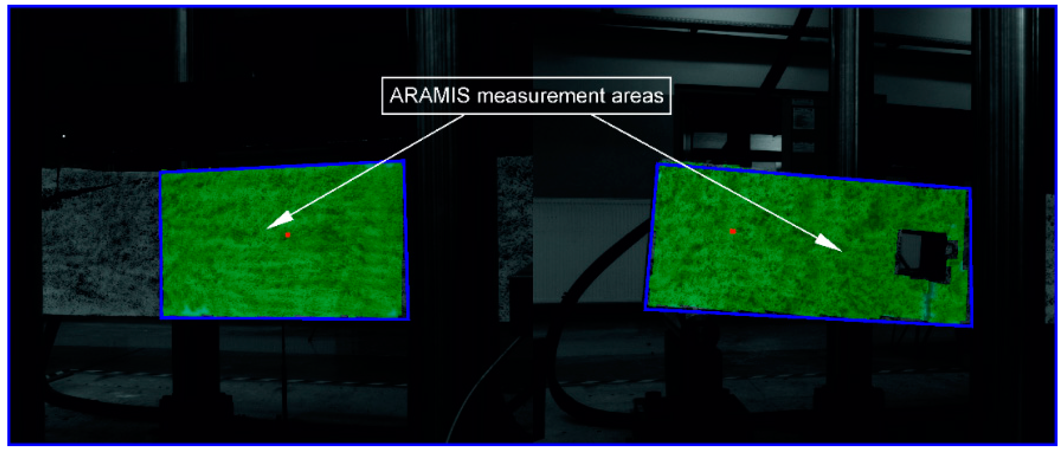
2.3. Testing Procedure

ARAMIS is a non-contact, 3D deformation measuring system. It analyses, calculates and documents deformations of specimens. The graphical report of the results provides the best possible understanding of the tested element behaviour at the process of its loading on the measuring area ranged from 1 to 2000 mm. The surface structure of the measuring object is recognized on the basis of images taken with digital cameras on which each pixel is allocated the appropriate coordinates. The first image represents the undeformed state of the specimen. The next images are taken and recorded sequentially in its different load stages up to failure. With the help of the correlation algorithm and mathematical calculation, the specimen is computed from the radii intersections, camera positions and lens distortion. The specimen coordinates on a part of the surface are set up in a high-resolution grid reflecting the tested specimen. Then, the system compares the 3D coordinates of the specimen and calculates the 3D displacements and strains. Accuracy of the system when measuring displacements is 5 µm. Strains can be measured in a range of 0.01% up to several 100% [61].
The ARAMIS system is composed of a measuring sensor with two digital cameras with a resolution of 2048 × 2048 pixels, and a recording frequency of up to 12 Hz; stand for secure and stable hold of the sensor; sensor controller for the cameras power supply and to control image recording; high-performance computer; software; calibration set for various measurement areas as well as an optical trigger.
In this research program, all the beams were whitewashed with lime before the strength tests. Then, one side surface of each beam was randomly covered with a pattern made of black paint so that the system could compute the displacements of characteristic points. The measurement areas for the B-beams defined at the middle part were limited to dimensions (650 ÷ 900) × 400 mm due to the geometric configuration of the press. In the case of BO-beams, the areas near the openings were defined, Figure 2. Before the tests were carried out, the system was calibrated on the measuring area so that the analysed area was within the measuring space. The size of characteristic points, so-called facets equal to 15 × 15 pixels, were found on subsequent compared images. A unique sequence of grey measurement points was assigned to each facet. On the second surface of the beam, it is planned to perform independent measurements of the development and propagation of cracks.
Testing of the beams was conducted in a hydraulic machine as shown in Figure 3. All the specimens were examined to failure in four-point bending under static load at a rate of 0.4 mm/min. The beam surface was recognised on the basis of images taken with a frequency 0.2 Hz. In the different load stages, the facets were identified and followed by means of the unique grey level structures and the system determined the 2D coordinates of the facets from the corner points and the resulting centres. In the next stage, the 2D coordinates of the facets, observed from the both cameras lead to a common 3D coordinates using photogrammetric methods. The coordinates were read from the left and right sensor cameras taking into account the angle between the camera axes. After the successful computation, the data was processed in order to reduce the measuring noise.
Simultaneously, the development and propagation of cracks were monitored and marked on the second surface of each beam to follow up their growth, sequence and pattern of cracking. Measurements of the crack width in a range of 0.01 mm up to 1 mm were performed using the hand-held illuminated optical microscope Optika XC-100L. Visual identification of crack development was assisted by a surface coating of whitewash. A simple unmagnified comparator scale was used to assist in the estimation of crack widths exceeding 1 mm. The deflections were recorded by means of linear variable displacement transducers (LVDT) mounted at the bottom of the beams at the mid-span.

3. Experimental Results and Discussion

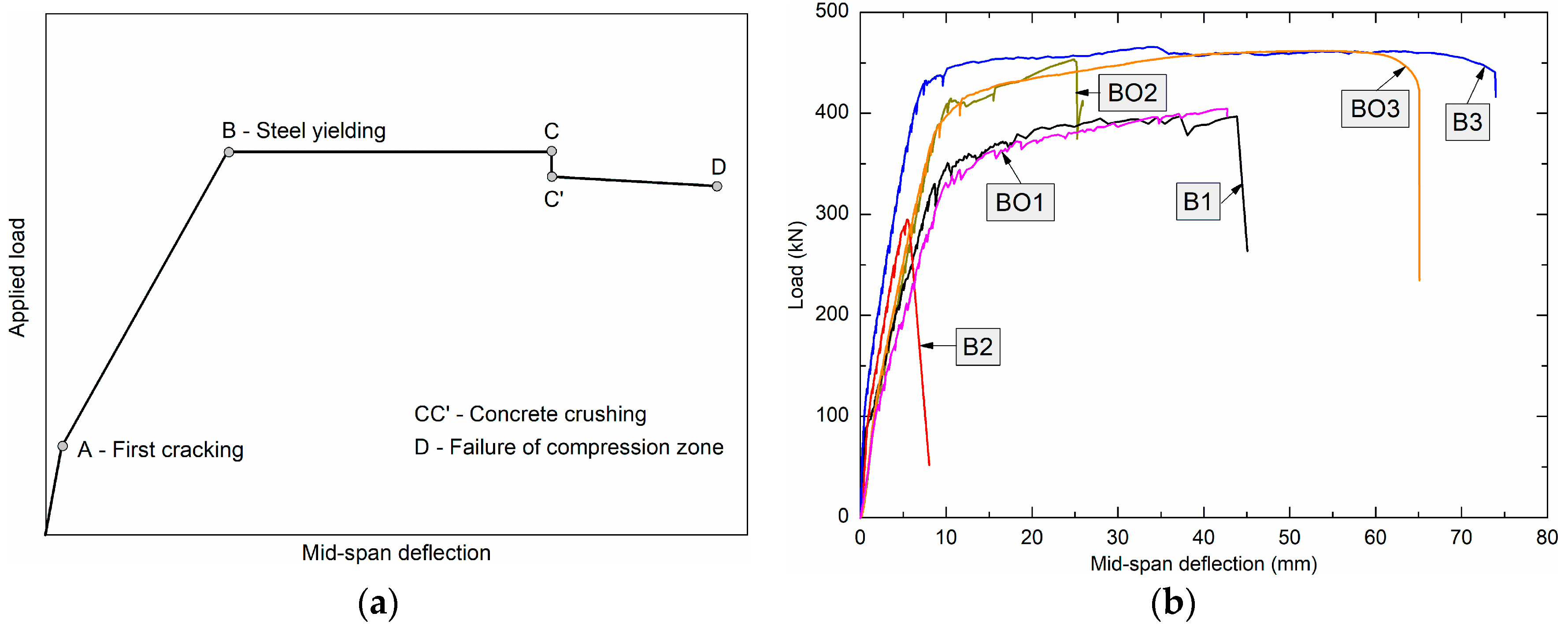
3.1. Load-Deflection Curves and Cracking Behaviour

3.1.1. Load-Deflection Curves

Figure 4 presents the load-deflection response curves of control beams B1 and BO1, simulating the behaviour of conventional RC without/with openings, respectively, and the other four beams with shear reinforcement in the form of different hybrid fibre volume contents. The mid-span deflections were recorded at the centre of the beams at each loading stage to determine the cracking, yielding, peak and ultimate loads. In general (Figure 4a), the response curves can be divided into three stages: the initial stiffness stage (0A), pre-yield stage (AB) and post-yield strain hardening stage (BD). Points A, B, C, C’, and D were identified as first flexural cracking, yielding of tensile reinforcement, initiation of concrete crushing, final spalling of the concrete cover in the compression zone, and ultimate collapse of the compressed HPC related to buckling of compression bars or/and fracture of the lateral ties, respectively. A straight line may approximate the curve in between two points. In test beams (with exception of B2), yielding of tensile reinforcement was started before crushing of the cover concrete and ultimate failure occurred due to disintegration of the confined HPC. Beams B3 and BO3 with the higher fibre content show higher yield strength values and also significant post-yield strain hardening behaviour.

3.1.2. Cracking and Yielding Load

The development of cracks at each stage of loading (every 25 kN) was monitored, marked and measured on the beams until the load level at which new cracks did not occur. At the last stage the beams were tested up to failure under monotonic loading. The tests were controlled by displacement and the deformation rate was 0.4 mm/min.
External loads result in bending and direct stresses, initiating flexural, bond, and shear cracks. When the tensile stress in the concrete exceeds its tensile strength, internal microcracks occur. These cracks generate into macrocracks propagating to the external edges of the member. After the first crack developed in RC beam, the stress in the concrete at the cracking zone is reduced to zero and is assumed by the steel bar. The first cracking load values were obtained from the load-deflection curves, the visual identification of crack, as well as the major strains images measured and calculated in the ARAMIS system. The secant stiffness at the point of two-thirds of the maximum load is applied to idealize the elastoplastic curve that passes through the maximum point of the load–deflection relationship. Then the deflection at an intersecting point between the two lines is used to determine the yielding load on the curve [62]. Table 4 summarizes the test results including the loading stages and corresponding beam deflections at cracking and yielding load. Cracking load is the point on the curve where the first flexural crack appears. It is used to calculate the initial stiffness of beams. The yielding load values were obtained from monitoring the load-deflection results.
It can be seen from this table that increasing the fibre volume content of the beams resulted in increases in their cracking load, even for the beams with the openings. The increment in cracking loads in the FRC beams with openings arises from the corresponding increase in flexural strength of the fibre concrete and a decrease in the W/B ratio. These increments in cracking load were 4–23% and 45–47% for series B and BO, respectively, by doubling the fibre content. A rise in the yielding loads was observed with an increase in fibre content. For the 1.05% fibre content the increase was 23% for the B3 beam, and 25% for the BO2 beam with the openings as compared to the beams without fibres. The lower increase in the yielding load of the beam B3 than that in BO2 is effect of difference in the W/B ratio associated with a different arrangement of reinforcement. On the other hand when the fibre content was 1.6%, the increase was 25% for beam BO3. The yielding loads of the BO beams with openings were slightly lower than those of the B beams. The difference was about 4.3%. This proves that using hybrid fibres, especially in beams with openings is beneficial.

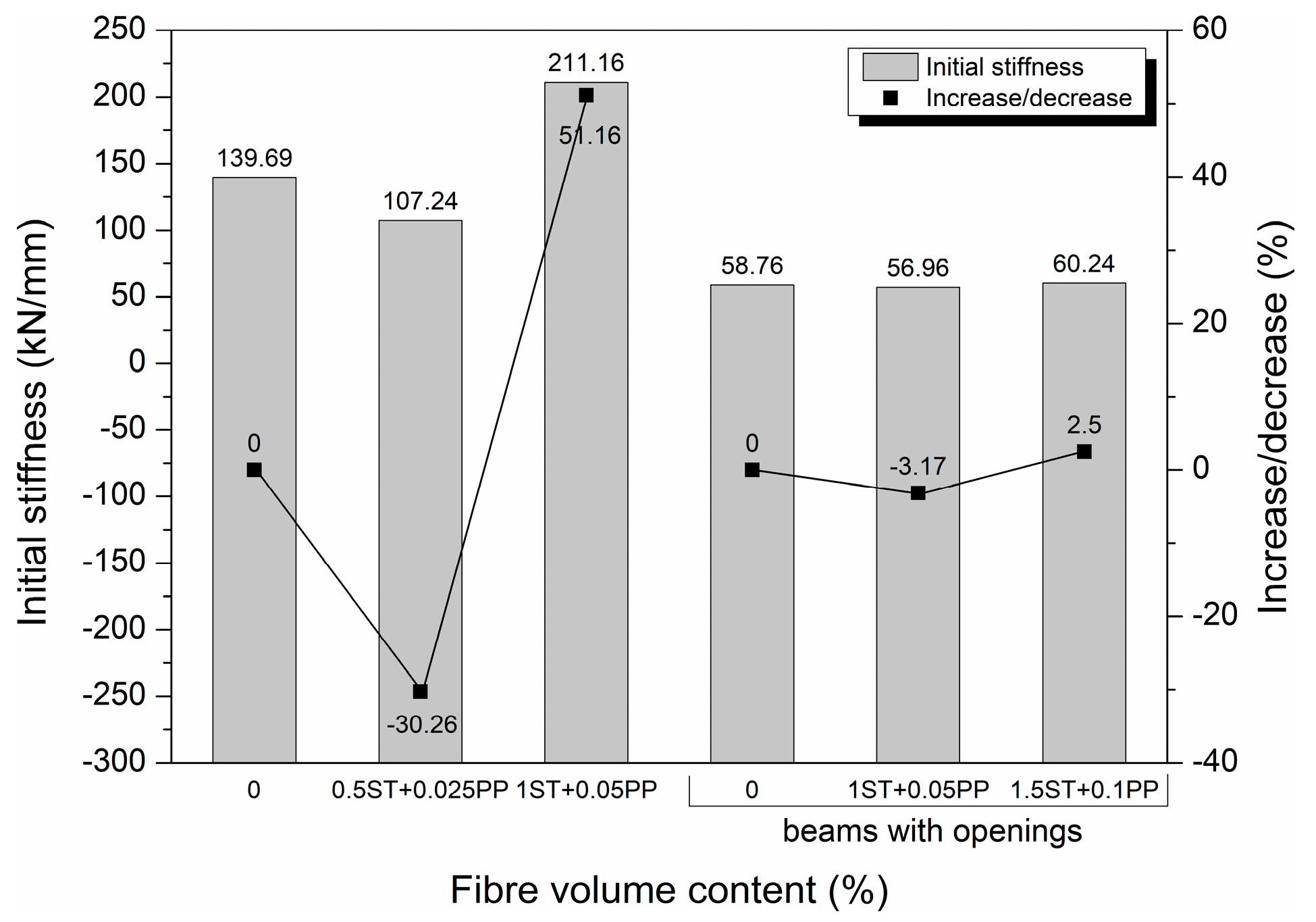
3.1.3. Initial Stiffness

The initial stiffness of the fibre beams B2 and BO2 shows lower values in comparison with that of traditionally RC beams (Table 4). In contrast, beams B3 and BO3 show higher values of the initial stiffness in comparison with that of control beams B1 and BO1, respectively. The decrease in the stiffness of the fibre beams B2, BO2 is affected by both the increase in cracking load and the increase in cracking deflection, which are effects of the different arrangement of reinforcement associated with a low steel and polypropylene fibre volume content as well as the lack of top bars and stirrups. On the other hand, the increase in the initial stiffness of FRC beams B3 and BO3 is a result of the increase in the cracking load of these beams and decrease in cracking deflection, which is an effect of the high fibre application. The observed behaviour is apparent in Figure 5.

3.1.4. Ultimate Load

All the values of maximum loads, ultimate loads and failure modes of the beams are given in Table 5. The ultimate load is defined as the load dropped to 80% of the maximum load.
The increase in hybrid fibre content raised the ultimate load capacity by about 17.51% for the B3 beam and 11.89–14.27% for the beams with openings. Steel and polypropylene fibres in the amount at least of 1% and 0.05% respectively provided the great benefits. For the beam with lower fibre content, a fall in the ultimate load and change in the failure mode were observed.

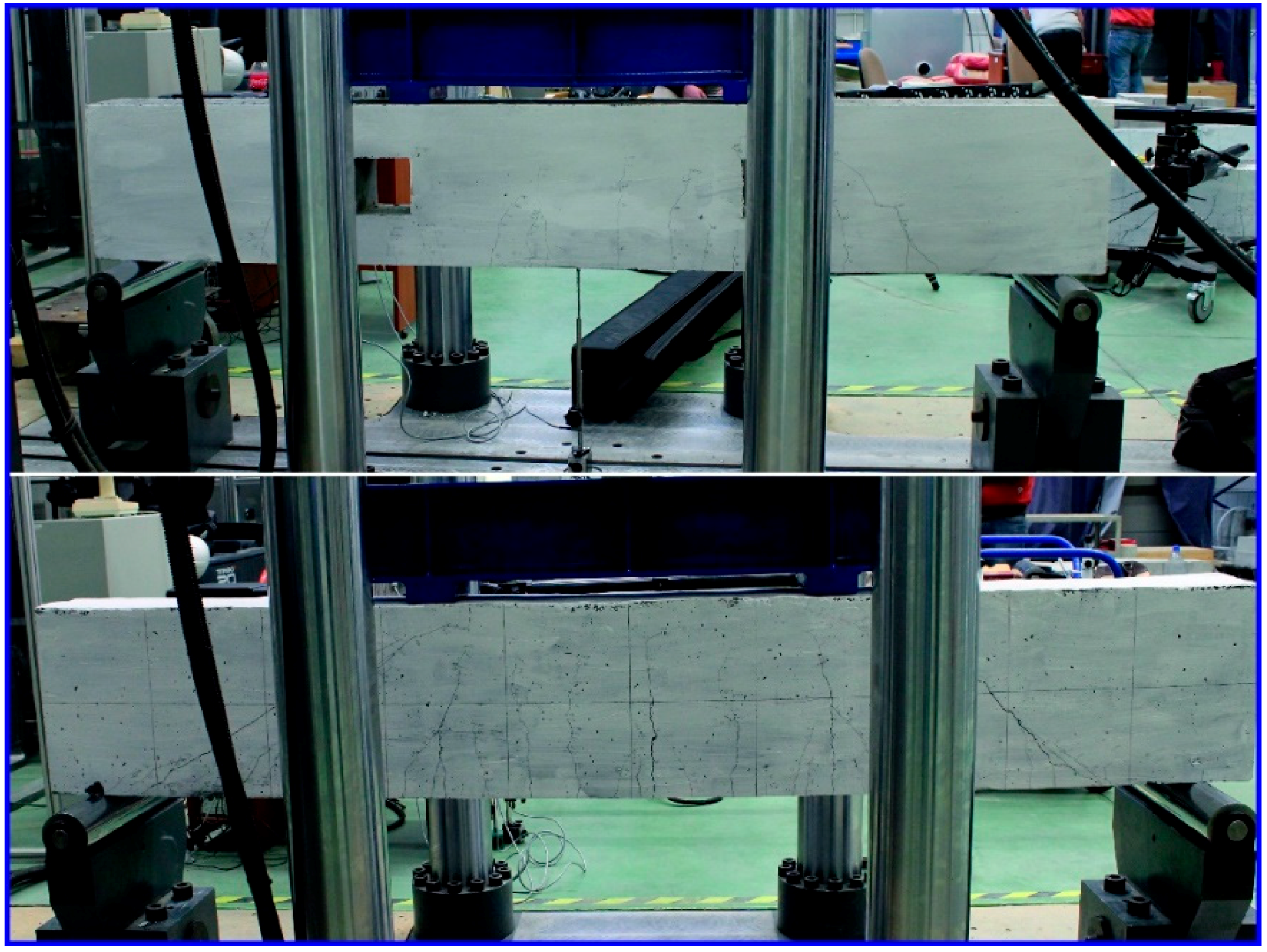
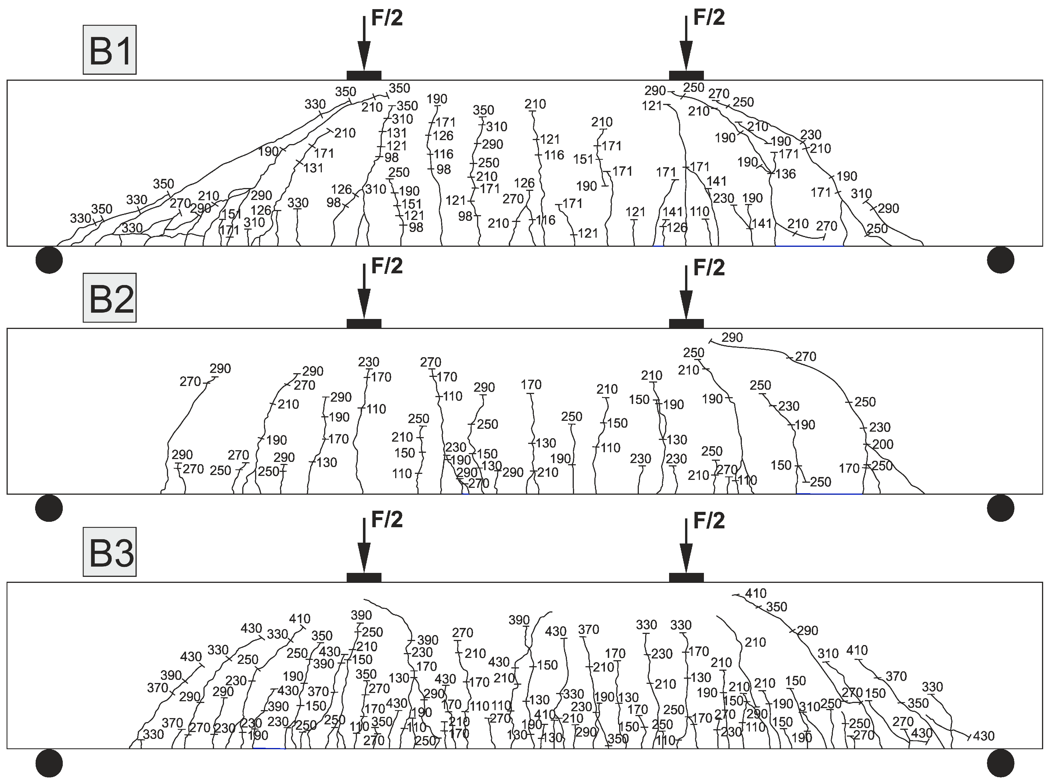
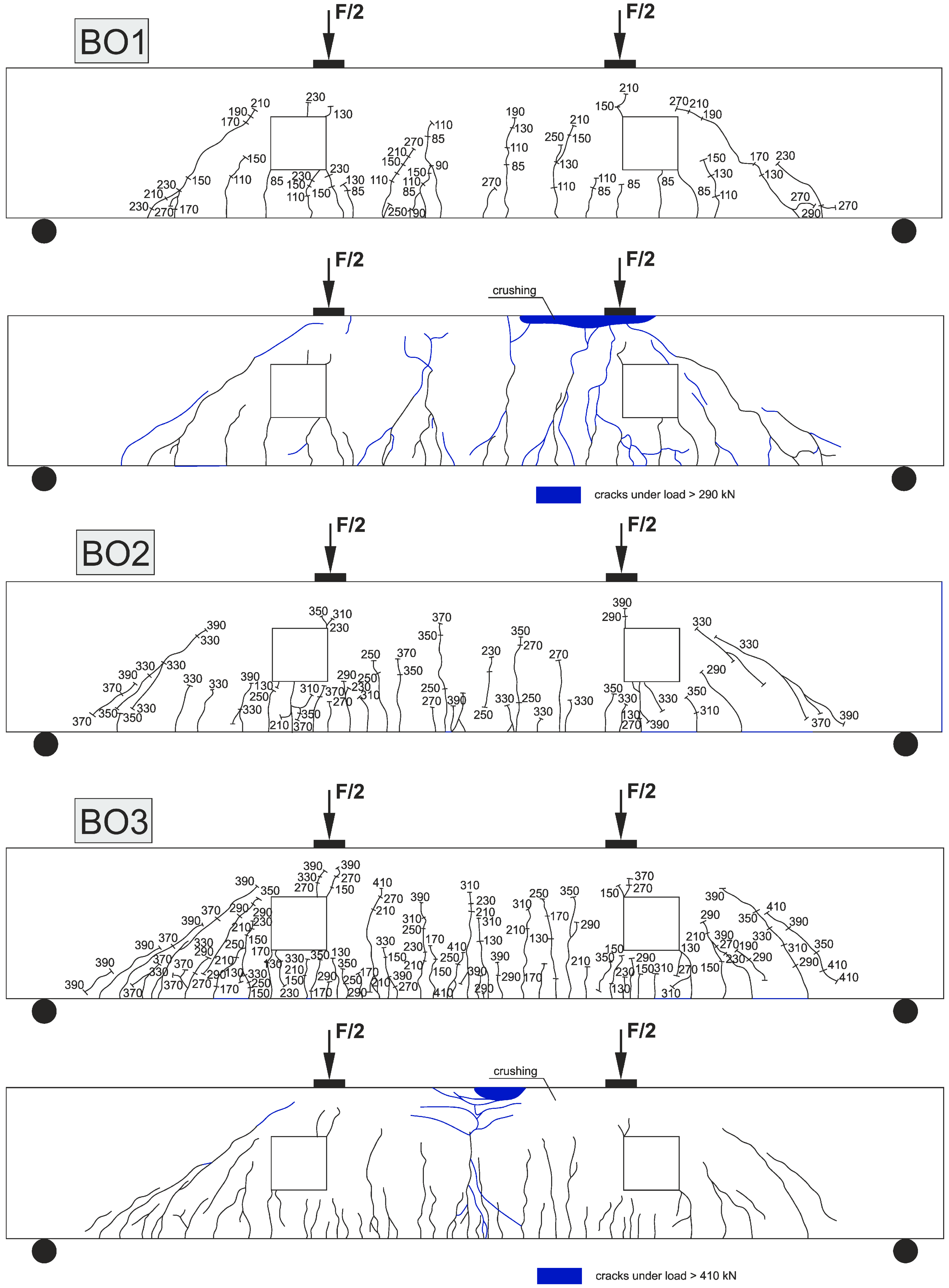
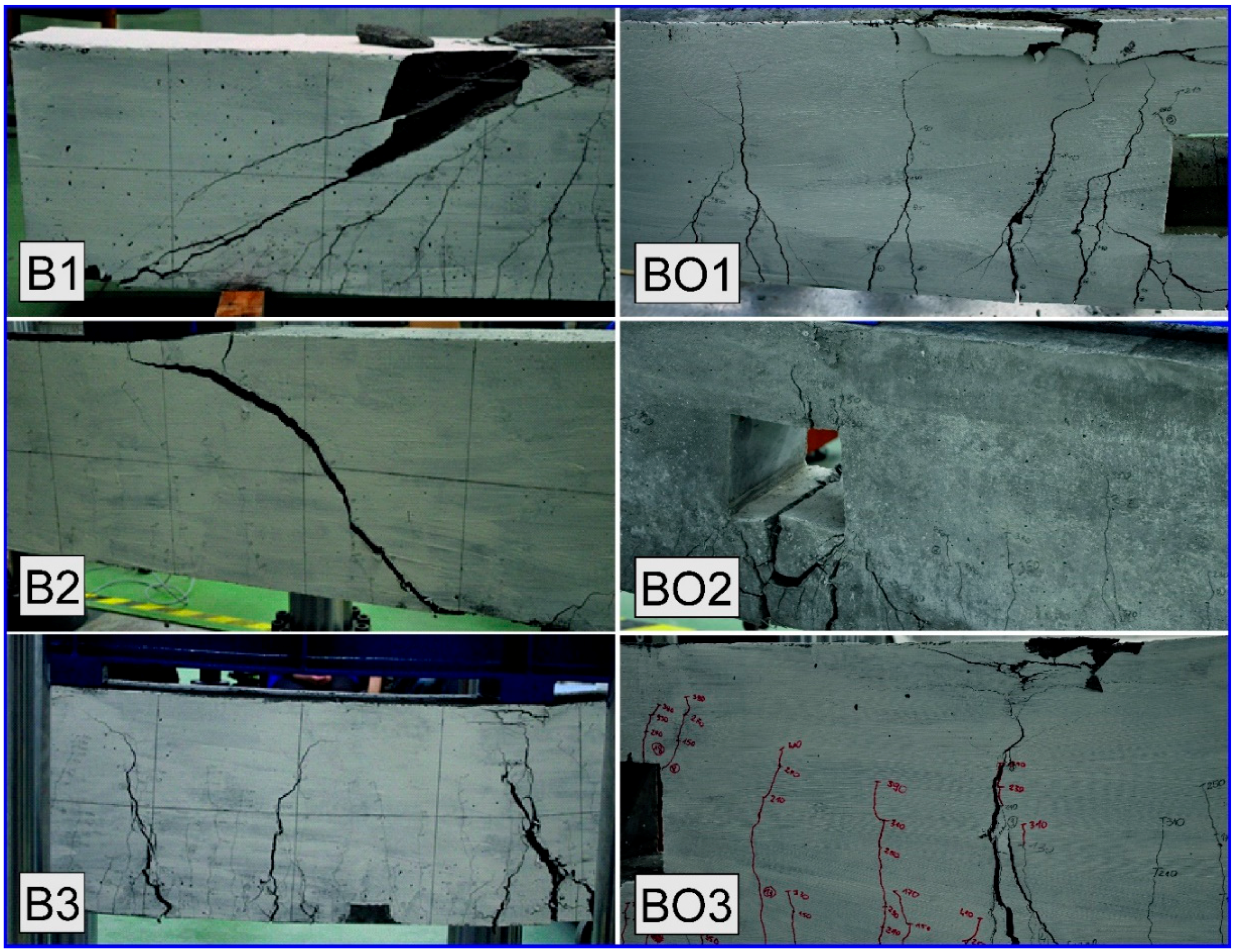
3.1.5. Cracking Patterns and Failure Modes

The cracks of all the tested beams at different loading stages are illustrated in detail in Figure 6. The crack shapes and their corresponding load levels are drawn. The first crack in the B beams always appeared in the middle zone, due to the high moment applied in this zone. Cracks in the BO beams were first observed below the openings. Diagonal cracks appeared at the mid-height of the B beams within the clear shear span in the direction of the main strut as the load increased to 78–85% (for the beams with fibres) and 53% (for the traditionally reinforced beam) of the ultimate load. In the next stages of loading, diagonal cracks propagated rapidly toward the cylindrical support and the outside edge of the loaded point. Their widths increased in the centre of the shear span, while diagonal cracks developed across the natural shear splitting line. Moreover, other diagonal cracks, parallel to the first crack were observed in the traditionally RC beam without fibres. Diagonal cracks in the BO beams were first observed below the corners of the opening. The diagonal cracking load of the BO beams with fibres was in the range of 49–91% of the ultimate load. On the other hand, the diagonal crack in the traditionally RC beam with openings appeared as the load increased to 46% of the ultimate load. It can be noticed that the openings had a significant impact on the cracking load. When the beams with fibres had openings the cracking load was increased. The cracks and location of the concrete crushing in the compression zone that appeared in the post-yield strain hardening stage were marked in blue. It was observed that in a fibre-free beam BO1 a larger number of cracks and a larger crushing area were formed in this loading stage. As given in Table 6, the final patterns of all the cracks were created in the beams at loading levels ranging between 125.6–163.9%, 92.1–100.2%, 75.4–98.4% and 94.2–123% for the cracking, yielding, maximum and ultimate loading stages, respectively. The applied load means the load at which the final patterns of all the cracks were created. Furthermore, the service load was determined as the experimental maximum load multiplied by 0.6 based on Kheder et al. [63]. The widest crack appeared accidentally in the zone of operation of the fixed moment in the B beams and under the openings of the BO beams. On the other hand, the widest crack in the BO beams occurred near the openings.
The loading stages and failure modes of the beams are shown in Table 5 and Figure 7. In general, the high-performance FRC beams tested in this study exhibited failure modes similar to the identical beams without fibres. Obviously, the highest percentage of steel and polypropylene fibres (B3, BO3) transformed the failure mode into a more ductile one. It can be observed that the flexural failure mode is characterized by cracks that occur gradually, allowing the beam to reach significant ductility. The beam with the lowest fibre content (B2) failed soon after the first diagonal crack appeared. Several diagonal cracks were observed for beams with a relatively high percentage of fibres (B3, BO2, BO3), thus indicating stress redistribution beyond cracking. In particular, the steel fibres became effective in transferring the tensile stresses after diagonal cracks formed, and bridging them until the fibres were pulled out or broken off at crack failure. This was also observed by other researchers [20,29,64]. The effectiveness of the fibres, the addition of 1% steel fibres and 0.05% polypropylene fibres to full beam B3 and the fibre content of 1.5% steel fibres and 0.1% polypropylene fibres to beam BO3 with openings transformed the failure mode from flexure-shear to mainly flexure (Figure 7). This confirms the beneficial effect of hybrid fibres in resisting shear failure. Beam B2 with a 0.5% steel fibre and 0.025% polypropylene fibre content failed in shear and exhibited rapid failure at the ultimate stage. Brittle failure occurs for the B1 and BO1 beams without fibres. The cracks are more localized above and along the inclined line joining the loading point with the support. The tests showed that stirrups are subjected to large deformations, which can indicate attainment of the yield limit. Rupture of the stirrup crossing the cracked section appears when the spacing between the stirrups is 130 mm for beam BO1 or 185 mm as in case of beam B1. This phenomenon might be eliminated by the addition of fibres.

3.1.6. Crack Spacing and Widths

The cracks’ spacing and width were measured at the tension reinforcement level. The minimum, maximum and average crack spacing decreased with an increase in fibre content due to the rise in the beam load-bearing capacity. The crack spacing and final number of cracks are shown in Table 7.
Kwak et al. [20] observed that average crack spacing in steel fibre RC beams with 0.5 to 0.75% fibre content was approximately 38% smaller compared with that of RC beams without fibres. Dinh et al. [29] reported that the average horizontal crack spacing for steel fibre RC beams without stirrups was approximately 0.4 d with 0.75 to 1.5% fibre content. Shoaib et al. determined the average horizontal crack spacing at the mid-depth level was by considering all the distinct inclined cracks that propagated beyond the specimen mid-depth level at angles between 0 and 75° with respect to the longitudinal axis of the specimen. The average crack spacing at mid-depth level for beams with h = 308, 600, or 1000 mm ranged from 0.39 d to 0.6 d, 0.43 d to 0.6 d, and 0.35 d to 0.47 d, respectively [64].
The test results from the current study showed that the increase in fibre content for beam series B (from 0.53% to 1.05%) and BO (from 1.05% to 1.6%) in comparison to traditionally RC beams resulted in a drop in the average crack spacing by 7.9–86.3% and 4.9–6.2%, respectively. The average crack spacing for steel and polypropylene fibre RC beams without stirrups was 0.14 d to 0.24 d (for B beams with h = 400 mm). The crack spacing of the BO beams with openings and without stirrups was about 0.22 d with 1.05 to 1.6% fibre content. The reason for this behaviour is that crack spacing is dependent on the ratio of tensile strength to bond strength between the concrete and reinforcement (steel bars and fibres). The increase in tensile strength is lower than the increase in bond strength so their ratio decreases, thus a smaller distance between cracks is required to transfer the tensile stresses from the reinforcement and fibres the concrete. This means the smallest crack spacing will occur in the RC beams with the highest fibre content. It can be noted that the ratios of minimum/average crack spacing and maximum/average crack spacing for the beams with hybrid fibres was similar (except for the B3 beam with the highest number of cracks) and ranged between 0.160–0.195 and 1.805–1.827, respectively.
The influence of fibre content on crack width is clear from Table 8. Increasing the fibre content from 1% steel fibres and 0.05% polypropylene fibres to 1.5% ST fibres and 0.1% PP fibres, resulted in a decrease in crack width at each of four loading stages. Interesting behaviour concerning the crack widths in the beams with fibres is given in Table 8, the crack widths in B2, B3 and BO3 are less than both the B1 and BO1 beams for all the loading levels. The flexural rigidities of the FRC beams are higher than traditionally RC beams. Smaller curvature and deflection resulted in narrower cracks in the FRC beams. This research and previous study [64] showed that the width of the diagonal crack in a FRC beams increases considerably at loads just before failure.

3.2. Inelastic Parameters

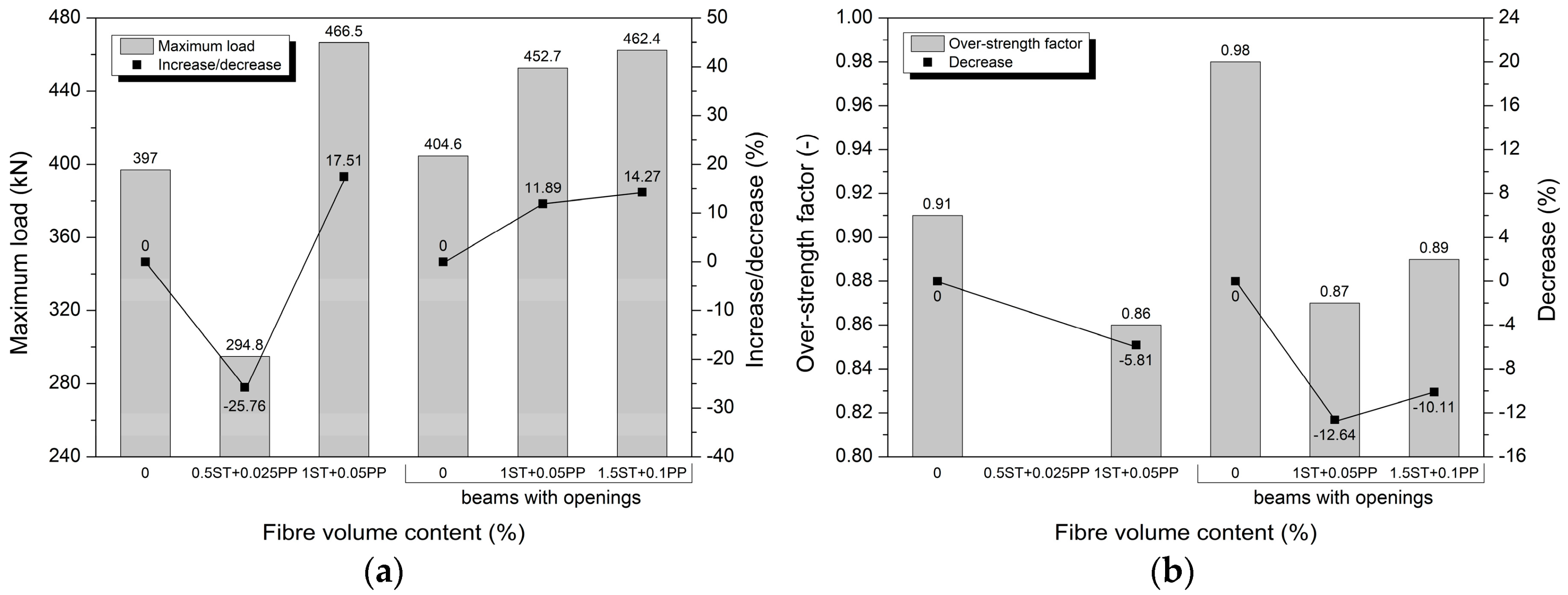
3.2.1. Maximum Load and Over-Strength Factor
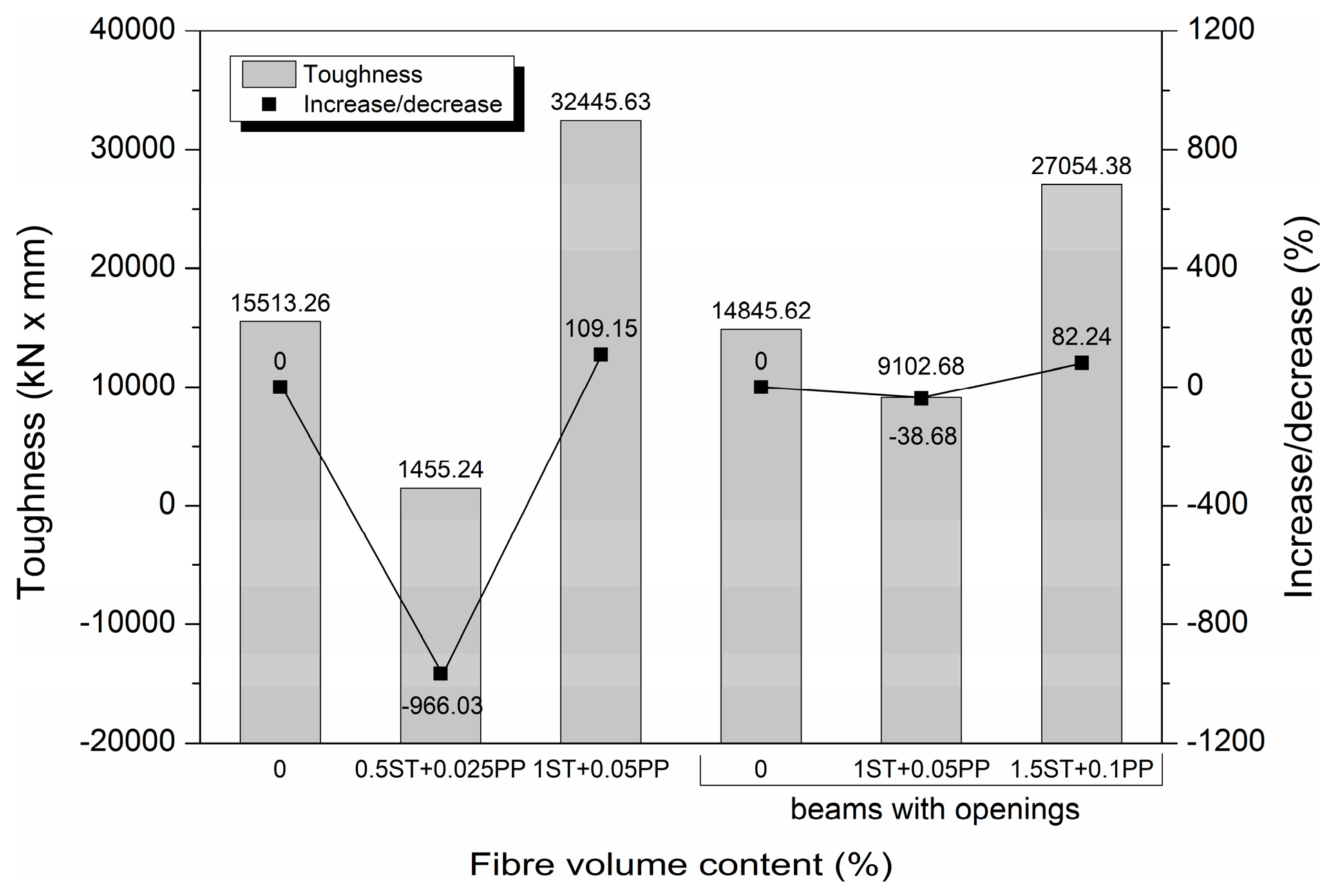
All the inelastic performance parameter values of the beams are shown in Table 9. The over-strength is specified as member capacity and is usually defined using over-strength factor. This factor is a parameter of the strain hardening, number of structural redundancies, deflection constraints and fibre content volume, which may be defined as the ratio of ultimate load to the yield load of the beams [65].
The first comparative parameter for the beams is the increase in maximum load, which reflects the effect of different fibre volume contents on increasing the load-bearing capacity. Beams B3 and BO2 with the inclusion of 1% ST fibres and 0.05% PP fibres and beam BO3 with 1.6% ST + PP fibres content presented the highest increases in maximum load, 17%, 12% and 14% respectively, comparing to the beams with stirrups. The beam with the lowest fibre content exhibits the greatest decrease in maximum load, 26%. Figure 8a shows the values of maximum loads for all the tested beams. The FRC beams have lower over-strength factor values in comparison with RC beams B1 and BO1, Figure 8b. The over-strength factor is not calculated for the B2 beam because the yield load is not reached. This shows the dominant action of stirrups in the first stage of strain hardening.

3.2.2. Toughness

Toughness reveals the energy absorption capacity of beams with/without openings. It is assessed by measuring the area under the load-deflection curve. The toughness values are calculated and shown in Figure 9 for comparing the impact of fibre volume content on increasing the toughness of beams with or without openings. As can be seen, the lowest value of toughness belongs to beam B2, which is about 11 times lower than conventional beam B1. Beams B3 and BO3 with the highest fibre content show an increase of 109.2% and 82.2% in toughness, both higher than that of traditionally RC beams. Beam BO2 exhibits a 38.7% decrease, which can be explained as a result of the presence of a square opening in the shear span.

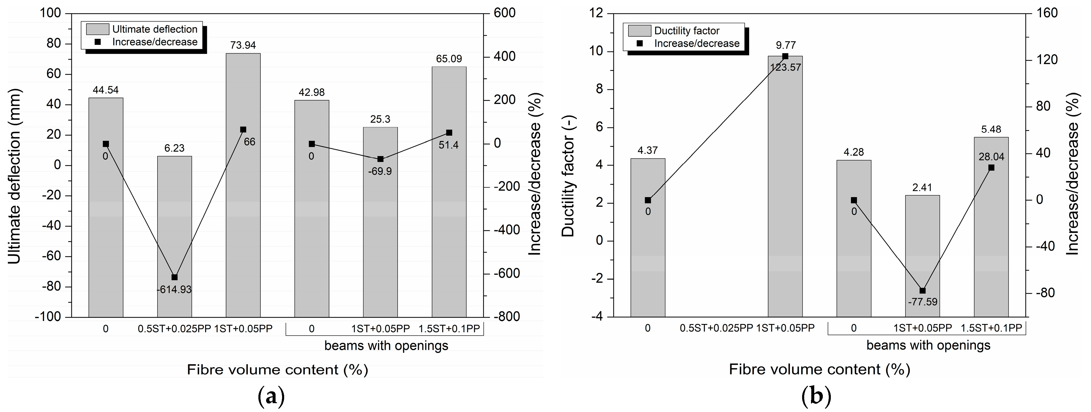
3.2.3. Ultimate Deflection and Ductility Factor
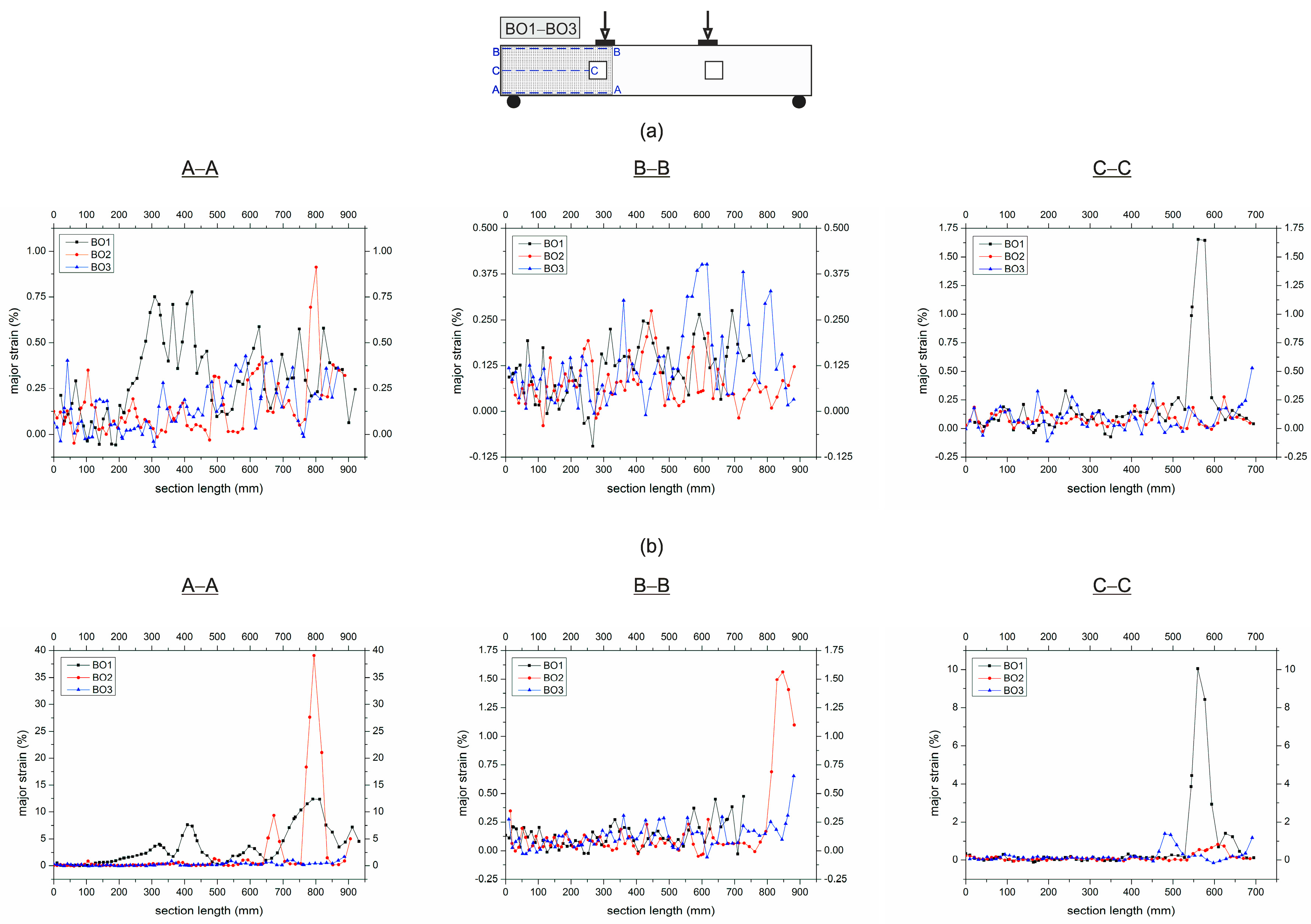
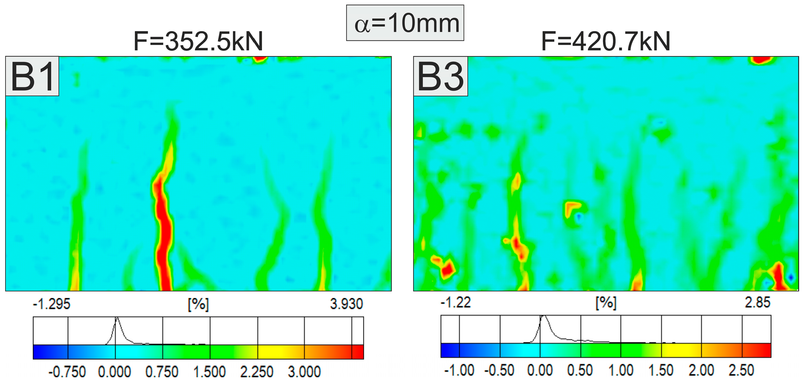
The ultimate inelastic deflection of the beams used for calculating the ductility factor is related to the strength at which the ultimate strength is observed. Thus, the ductility factor is defined as the ultimate structural deflection to the yield strength deflection. The values of these parameters are plotted in Figure 10.
As can be seen, beams B3 and BO3 with the highest hybrid fibre content, 1.05% and 1.6%, gained increases in the ultimate deflection, 66% and 51.4%, respectively. In the case of beam BO2 with openings and a 1.05% fibre content, the value of this parameter shows a decrease of 69.9%. In consequence, the evaluated values of ductility indicate the positive impact of hybrid fibres on increasing the ductility even more than that of shear reinforcement when an appropriate fibre volume content is applied. Similar to the ultimate deflection, the increases in the ductility factors are for beams B3 and BO3 with the 1.05% and 1.6% fibre content, 123.6% and 28%, respectively. In contrast, a decrease of 28% in the ductility factor is noted for beam BO2 with openings.

3.3. Strains

The major strains in the concrete and hybrid fibre concrete in the beams without/with openings, together with the location of longitudinal sections and measurement areas for the beams in the ARAMIS system are shown in Figure 11 and Figure 12. The major strain curves were made in longitudinal sections A-A and B-B located respectively in the tension and complex stress state area in the mid-span of beams B1 ÷ B3. In beams BO1 ÷ BO3 with the openings, the longitudinal sections A-A, B-B and C-C are located in the shear span in the area of complex stress state. An additional longitudinal section C-C is located at half the height of these beams. Based on the non-contact measurements of strains, the essential differences in the concrete and fibre concrete strain distributions may be observed.
The major strains in the longitudinal sections of the tested beams depends on the type of reinforcement, the fibre volume content and the openings in the shear span. The mean strain values in the B1, B2 and B3 beams at the service load near the tensile edge (in section A-A) determined on the basis of statistical analysis are 0.22, 0.17 and 0.39%, respectively, and near the compressive edge (in section B-B) they are 0.061, 0.043 and 0.058%. The mean strains of beams B1-B3 at the maximum load are respectively 2.12, 0.28 and 2.28% (in section A-A) and 0.111, 0.043 and 0.043% (in section B-B). The major strains at the bottom of the beams without fibres and with the highest fibre content increased approximately 10 and 6 times. On the other hand, at the upper edge the strains increased almost two-fold in the reinforced bar and decreased by 35% in the beam with the highest fibre content. Figure 13 shows the comparison of the major strain images for the B1 and B3 beams at the constant deflection of 10 mm. It can be noticed that the highest strain of beam B3 is about 28% lower than the highest strain of beam B1 without fibres.
The major strains of beams B1 ÷ B3 at maximum load are illustrated in Figure 14. The highest values of strains in the B1 and B3 beams are observed near the widest crack and are equal to 12.2 and 22%, respectively. Nevertheless, the greatest measured strain of the B2 beam is much lower and amounted to 1.4%. In this case, however, the greatest strain occurred in the shear span, outside the measuring field. The mean strains at service and maximum load of the BO1, BO2 and BO3 beams with openings are 0.3%, 0.15%, 0.14% and 3.11%, 2.02%, 0.25% in section A-A, respectively, and 0.12%, 0.08%, 0.12% and 0.14, 0.16, 0.12% in section B-B, and 0.2, 0.08, 0.1% and 0.71%, 0.13%, 0.19% in section C-C. The lowest values of strain at the tensile edge of the beam are noted in the BO3 beam with the highest fibre content.
In the strain images of the BO beams at maximum load shown in Figure 14, it can be noticed that diagonal cracks propagate from the support to the upper edge of the opening in fibre beams BO3 and BO2, which is reflected in about 3.5–5.5 times lower mean strains in the longitudinal section C-C in the beam mid-height compared to the BO1 beam with stirrups and without fibres. The reasons are to be found in another work mechanism of FRC beams with openings in which the development of diagonal cracks is inhibited by fibres constituting the only reinforcement of the shear zone additionally weakened by the hole.

4. Conclusions

The study reported in this paper mainly investigates the implications of using hybrid steel/polypropylene fibres as shear reinforcement in reinforced HPC flexural beams with/without openings. The addition of hybrid fibres in an adequate percentage have the potential to considerably improve the performance of beams with/without openings in terms of toughness, stiffness, strength and ductility. Within the scope of this investigation, the following other conclusions derived from the current study can be made:
  • Full beams with a hybrid fibre content above 1% and beams with openings with the addition of fibres above 1.6% show the highest yield and maximum strengths as well as post-yield strains.
  • The increase in hybrid fibre content increased the first cracking load, ultimate load capacity, toughness, ductility, and resulted in a decrease in the average crack spacing, crack width as well as strains in comparison to traditionally RC beams. The greatest benefits were observed for fibres in an amounts of at least 1% and 1.6% in B and BO beams, respectively.
  • For the beams B2, BO2 with the lower fibre content, a decrease in ultimate load and transformation to the sudden shear failure mode were noticed.
  • The ratios of minimum/average crack spacing and maximum/average crack spacing for the beams with hybrid fibres was similar.
  • The openings had a significant impact on the decrease in crack spacing, toughness and ductility factor.

Funding

This research received no external funding.

Acknowledgments

This work was financially supported by the Ministry of Science and Higher Education—Poland, within statutory research number S/15/B/1/2017.

Conflicts of Interest

The author declares that this article content has no conflict of interest.

References

  1. Mathey, R.G.; Watstein, D. Shear Strength of Beams without Web Reinforcement Containing Deformed Bars of Different Yield Strengths. J. ACI 1963, 60, 183–208. [Google Scholar] [CrossRef]
  2. Krefeld, W.J.; Thurston, C.W. Contribution of longitudinal steel to shear resistance of reinforced concrete beams. J. ACI 1966, 63, 325–344. [Google Scholar] [CrossRef]
  3. Kani, G.N.J. Basic Facts Concerning Shear Failure. J. ACI 1966, 63, 675–692. [Google Scholar] [CrossRef]
  4. Rajagopolan, K.S.; Ferguson, P.M. Exploratory Shear Tests Emphasizing Percentage of Longitudinal Steel. J. ACI 1968, 65, 634–638. [Google Scholar] [CrossRef]
  5. Bažant, Z.P.; Kim, J. Size Effect in Shear Failure of Longitudinally Reinforced Beams. J. ACI 1984, 81, 456–468. [Google Scholar] [CrossRef]
  6. Angelakos, D.; Bentz, E.C.; Collins, M.P. Effect of Concrete Strength and Minimum Stirrups on Shear Strength of Large Members. ACI Struct. J. 2001, 98, 290–300. [Google Scholar] [CrossRef]
  7. Collins, M.P.; Bentz, E.C.; Sherwood, E.G. Where is Shear Reinforcement Required? Review of Research Results and Design Procedures. ACI Struct. J. 2008, 105, 590–600. [Google Scholar] [CrossRef]
  8. Caldentey, A.P.; Padilla, P.; Muttoni, A.; Ruiz, M.F. Effect of Load Distribution and Variable Depth on Shear Resistance of Slender Beams without Stirrups. ACI Struct. J. 2012, 109, 595–603. [Google Scholar] [CrossRef]
  9. Shah, S.P.; Rangan, B.V. Fiber reinforced concrete properties. ACI J. 1971, 68, 126–135. [Google Scholar] [CrossRef]
  10. Swamy, R.N.; Mangat, P.S.; Rao, C.V.S.K. The Mechanics of Fibre Reinforcement of Cement Matrices. In Fiber Reinforced Concrete; ACI Special Publication SP–44; American Concrete Institute: Detroit, MI, USA, 1974; pp. 1–28. [Google Scholar]
  11. Kormeling, H.A.; Reinhardt, H.W.; Shah, S.P. Static and fatigue properties of concrete beams reinforced with continuous bars and with fibers. ACI J. 1980, 77, 36–43. [Google Scholar] [CrossRef]
  12. Swamy, R.N.; Al-Ta’an, S.A. Deformation and ultimate strength in flexure of reinforced concrete beams made with steel fibers. ACI Struct. J. 1981, 78, 395–405. [Google Scholar] [CrossRef]
  13. Swamy, R.N.; Bahia, H.M. The effectiveness of steel fibers as shear reinforcement. Concr. Int. 1985, 3, 35–40. [Google Scholar]
  14. Rossi, P. Mechanical behavior of metal-fibre reinforced concretes. Cem. Concr. Compos. 1992, 14, 3–16. [Google Scholar] [CrossRef]
  15. Oh, B.H. Flexural analysis of reinforced concrete beams containing steel fibers. J. Struct. Eng. 1992, 118, 2821–2826. [Google Scholar] [CrossRef]
  16. Imam, M.; Vandewalle, L.; Mortelmans, F. Shear-moment analysis of reinforced high strength concrete beams containing steel fibres. Can. J. Civ. Eng. 1995, 22, 462–470. [Google Scholar] [CrossRef]
  17. Wang, N.; Mindess, S.; Ko, K. Fibre reinforced concrete beams under impact loading. Cem. Concr. Res. 1996, 26, 363–376. [Google Scholar] [CrossRef]
  18. Furlan, S., Jr.; De Hanai, J.B. Shear behaviour of fiber reinforced concrete beams. Cem. Concr. Compos. 1997, 19, 359–366. [Google Scholar] [CrossRef]
  19. Casanova, P.; Rossi, P. Analysis and design of steel fiber reinforced concrete beams. ACI Struct. J. 1997, 94, 595–602. [Google Scholar] [CrossRef]
  20. Kwak, Y.K.; Eberhard, M.O.; Kim, W.S.; Kim, J. Shear strength of steel fiber reinforced concrete beams without stirrups. ACI Struct. J. 2002, 99, 530–538. [Google Scholar] [CrossRef]
  21. Banthia, N.; Gupta, R. Hybrid fiber reinforced concrete (HyFRC): Fiber synergy in high strength matrices. Mater. Struct. 2004, 37, 707–716. [Google Scholar] [CrossRef]
  22. Kang, S.-T.; Choi, J.-I.; Koh, K.-T.; Lee, K.S.; Lee, B.Y. Hybrid effects of steel fiber and microfiber on the tensile behavior of ultra-high performance concrete. Compos. Struct. 2016, 145, 37–42. [Google Scholar] [CrossRef]
  23. Batson, G.; Jenkins, E.; Spatney, R. Steel Fibers as Shear Reinforcement in Beams. ACI J. 1972, 69, 640–644. [Google Scholar] [CrossRef]
  24. Sharma, A.K. Shear Strength of Steel Fiber Reinforced Concrete Beams. ACI J. 1986, 83, 624–628. [Google Scholar] [CrossRef]
  25. Al-Ta’an, S.A.; Al-Feel, J.R. Evaluation of shear strength of fibre-reinforced concrete beams. Cem. Concr. Compos. 1990, 12, 87–94. [Google Scholar] [CrossRef]
  26. Adebar, P.; Mindess, S.; St-Pierre, D.; Olund, B. Shear Tests of Fiber Concrete Beams without Stirrups. ACI Struct. J. 1997, 94, 68–76. [Google Scholar] [CrossRef]
  27. Cucchiara, C.; La Mendola, L.; Papia, M. Effectiveness of stirrups and steel fibres as shear reinforcement. Cem. Concr. Compos. 2004, 26, 777–786. [Google Scholar] [CrossRef]
  28. Parra-Montesinos, G.J. Shear strength of beams with deformed steel fibers. Concr. Int. 2006, 28, 57–66. [Google Scholar]
  29. Dinh, H.H.; Parra-Montesinos, G.J.; Wight, J.K. Shear Behavior of Steel Fiber-Reinforced Concrete Beams without Stirrup Reinforcement. ACI Struct. J. 2010, 107, 597–606. [Google Scholar] [CrossRef]
  30. Dinh, H.H.; Parra-Montesinos, G.J.; Wight, J.K. Shear Strength Model for Steel Fiber Reinforced Concrete Beams without Stirrup Reinforcement. J. Struct. Eng. 2011, 137, 1039–1051. [Google Scholar] [CrossRef]
  31. Aoude, H.; Belghiti, M.; Cook, W.D.; Mitchell, D. Response of Steel Fiber-Reinforced Concrete Beams with and without Stirrups. ACI Struct. J. 2012, 109, 359–367. [Google Scholar] [CrossRef]
  32. Mansur, M.A.; Ong, K.C.G.; Paramasivam, P. Shear Strength of Fibrous Concrete Beams Without Stirrups. J. Struct. Eng. 1986, 112, 2066–2079. [Google Scholar] [CrossRef]
  33. Narayanan, R.; Darwish, I.Y.S. Use of Steel Fibers as Shear Reinforcement. ACI Struct. J. 1987, 84, 216–227. [Google Scholar] [CrossRef]
  34. Narayanan, R.; Darwish, I.Y.S. Shear in Mortar Beams Containing Fibers and Fly Ash. J. Struct. Eng. 1988, 114, 84–102. [Google Scholar] [CrossRef]
  35. Ashour, S.A.; Hasanain, G.S.; Wafa, F.F. Shear Behavior of High-Strength Fiber Reinforced Concrete Beams. ACI Struct. J. 1992, 89, 176–184. [Google Scholar] [CrossRef]
  36. Lim, D.H.; Oh, B.H. Shear behaviour and shear analysis of reinforced concrete members containing steel fibres. Korean Concr. J. 1993, 5, 171–180. [Google Scholar]
  37. Shin, S.W.; Oh, J.G.; Ghosh, S.K. Shear Behavior of Laboratory-sized High Strength Concrete Beams Reinforced with Bars and Steel Fibers. In Fiber Reinforced Concrete Developments and Innovations; Daniel, J.I., Shah, S.P., Eds.; ACI Special Publication SP–142; American Concrete Institute: Detroit, MI, USA, 1994; pp. 181–200. ISBN 978087031641. [Google Scholar]
  38. Biolzi, L.; Guerrini, G.L.; Rosati, G. Overall structural behavior of high strength concrete specimens. Constr. Build. Mater. 1997, 11, 57–63. [Google Scholar] [CrossRef]
  39. Iman, M.; Vandewalle, L.; Mortelmans, F.; Van Gemert, D. Shear domain of fibre-reinforced high-strength concrete beams. Eng. Struct. 1997, 19, 738–747. [Google Scholar] [CrossRef]
  40. Khuntia, M.; Stojadinovic, B.; Goel, S. Shear Strength of Normal and High-Strength Fiber Reinforced Concrete Beams without Stirrups. ACI Struct. J. 1999, 96, 282–290. [Google Scholar] [CrossRef]
  41. Biolzi, L.; Cattaneo, S.; Guerrini, G. Fracture of plain and fiber reinforced high strength mortars slabs with AE and ESPI monitoring. Appl. Compos. Mater. 2000, 7, 1–12. [Google Scholar] [CrossRef]
  42. Bencardino, F.; Rizzuti, L.; Spadea, G.; Swamy, R.N. Experimental evaluation of fiber reinforced concrete fracture properties. Compos. Part B Eng. 2010, 41, 17–24. [Google Scholar] [CrossRef]
  43. Casanova, P.; Rossi, P.; Schaller, I. Can steel fibers replace transverse reinforcements in reinforced concrete beams? ACI Mater. J. 1997, 94, 341–354. [Google Scholar] [CrossRef]
  44. Spinella, N. Shear strength of full-scale steel fibre-reinforced concrete beams without stirrups. Comput. Concr. 2013, 11, 365–382. [Google Scholar] [CrossRef]
  45. Biolzi, L.; Cattaneo, S. Response of steel fiber reinforced high strength concrete beams: Experiments and code predictions. Cem. Concr. Compos. 2017, 77, 1–13. [Google Scholar] [CrossRef]
  46. Afroughsabet, V.; Biolzi, L.; Ozbakkaloglu, T. High-performance fiber-reinforced concrete: A review. J. Mater. Sci. 2016, 51, 6517–6551. [Google Scholar] [CrossRef]
  47. Parra-Montesinos, G.J.; Reinhardt, H.W.; Naaman, A.E. (Eds.) High Performance Fiber Reinforced Cement Composites 6; Springer: Dordrecht, The Netherlands/Heidelberg, Germany; London, UK; New York, NY, USA, 2012. [Google Scholar]
  48. Suji, D.; Natesan, S.C.; Muregesan, R. Experimental study on behaviors of polypropylene fibrous concrete beams. J. Zhejiang Univ. Sci. A 2007, 8, 1101–1109. [Google Scholar] [CrossRef]
  49. FIB. Fib Model Code for Concrete Structures 2010; Wilhelm Ernst & Sohn; Verlag für Architektur und technische Wissenschaften GmbH & Co. KG: Berlin, Germany, 2013. [Google Scholar]
  50. EN 1992-1-1. Eurocode 2. Design of Concrete Structures Part 1-1: General rules and Rules for Buildings; European-Commission: Brussels, Belgium, 2004.
  51. Choi, K.K.; Hung-Gun, P.; Wight, J.K. Shear strength of steel fiber-reinforced concrete beams without web reinforcement. ACI Struct. J. 2007, 104, 12–21. [Google Scholar] [CrossRef]
  52. Spadea, G.; Bencardino, F. Behavior of fiber-reinforced concrete beams under cyclic loading. J. Struct. Eng. 1997, 123, 660–668. [Google Scholar] [CrossRef]
  53. Spinella, N.; Colajanni, P.; La Mendola, L. Nonlinear Analysis of Beams Reinforced in Shear with Stirrups and Steel Fibers. ACI Struct. J. 2012, 109, 53–64. [Google Scholar] [CrossRef]
  54. Smarzewski, P. Study of crack development and toughness of fiber reinforced ultra-high performance concrete after exposure to elevated temperature. In ICCS20 20th International Conference on Composite Structures; Structural and Computational Mechanics Book Series; Ferreira, A.J.M., Tornabene, F., Larbi, W., Deu, J.-F., Eds.; Società Editrice Esculapio: Bologna, Italy, 2017; pp. 118–119. [Google Scholar]
  55. PN-EN 12390-3. Testing Hardened Concrete. Compressive Strength of Test Specimens. 2011. Available online: http://sklep.pkn.pl/pn-en-12390-3-2011p.html (accessed on 25 October 2018).
  56. PN-EN 12390-6. Testing Hardened Concrete. Tensile Splitting Strength of Test Specimens. 2011. Available online: http://sklep.pkn.pl/pn-en-12390-6-2011p.html (accessed on 25 October 2018).
  57. PN-EN 12390-5. Testing Hardened Concrete. Flexural Strength of Test Specimens. 2011. Available online: http://sklep.pkn.pl/pn-en-12390-5-2011p.html (accessed on 25 October 2018).
  58. ASTM C469/C469M-14, Standard Test Method for Static Modulus of Elasticity and Poisson’s Ratio of Concrete in Compression; ASTM International: West Conshohocken, PA, USA, 2014. [CrossRef]
  59. PN-B-03264. Plain, Reinforced and Prestressed Concrete Structures—Analysis and Structural Design; DIN: Berlin, Germany, 2002.
  60. Nasser, K.W.; Acavalos, A.; Daniel, H.R. Behavior and Design of Large Openings in Reinforced Concrete Beams. ACI J. Proc. 1967, 64, 25–33. [Google Scholar] [CrossRef]
  61. ARAMIS v6.3. User Manual-Software; GOM mbH: Braunschweig, Germany, 2007.
  62. Pan, A.; Moehle, J.P. Lateral Displacement Ductility of Reinforced Concrete Flat Plates. ACI Struct. J. 1989, 86, 250–258. [Google Scholar] [CrossRef]
  63. Kheder, G.F.; Al Kafaji, J.M.; Dhiab, R.M. Flexural strength and cracking behavior of hybrid strength concrete beams. Mater. Struct. 2010, 43, 1097–1111. [Google Scholar] [CrossRef]
  64. Shoaib, A.; Lubell, A.S.; Bindiganavile, V.S. Size Effect in Shear for Steel Fiber Reinforced Concrete Members without Stirrups. ACI Struct. J. 2014, 111, 1081–1090. [Google Scholar] [CrossRef]
  65. Mitchell, D.; Paultre, P. Ductility and overstrength in seismic design of reinforced concrete structures. Can. J. Civ. Eng. 1994, 21, 1049–1060. [Google Scholar] [CrossRef]
Figure 1. Dimensions, reinforcement arrangement and opening regimes of test beams (unit in mm).
Applsci 08 02070 g001
Figure 2. Measurement area.
Applsci 08 02070 g002
Figure 3. Test setup.
Applsci 08 02070 g003
Figure 4. Load-deflection curves for beams: (a) idealized response; (b) experimental response.
Applsci 08 02070 g004
Figure 5. Comparison of beam initial stiffness.
Applsci 08 02070 g005
Figure 6. Crack patterns for beams.
Applsci 08 02070 g006aApplsci 08 02070 g006b
Figure 7. Beams failure modes.
Applsci 08 02070 g007
Figure 8. Comparison of beam (a) maximum load and (b) over-strength factor.
Applsci 08 02070 g008
Figure 9. Comparison of beam toughness.
Applsci 08 02070 g009
Figure 10. Comparison of beam (a) ultimate deflection and (b) ductility factor.
Applsci 08 02070 g010
Figure 11. Major strains of concrete beam (B1) and hybrid fibre concrete beams (B2, B3): (a) at service load, and (b) at maximum load.
Applsci 08 02070 g011
Figure 12. Major strains of concrete beam (BO1) and hybrid fibre concrete beams (BO2, BO3) with openings: (a) at service load, and (b) at maximum load.
Applsci 08 02070 g012
Figure 13. Comparison of major strains for B1 and B3 beams in measurement area, at deflection of 10 mm.
Applsci 08 02070 g013
Figure 14. Major strains of beams in measurement area at maximum load.
Applsci 08 02070 g014
Table 1. Mixture proportions.
MaterialSymbol, UnitB1B2B3BO1BO2BO3
Cement CEM I 52.5RC, (kg/m3)596596596596596596
Silica fumeM, (kg/m3)59.659.659.659.659.659.6
Granodiorite 2/8 mmA, (kg/m3)990990990990990990
Quartz sand 0.05/2 mmS, (kg/m3)500500500500500500
SuperplasticiserSP, (l/m3)202020202020
WaterW, (l/m3)196196196164164164
Steel fibreST, (kg/m3)397878117
VST, (%)0.5111.5
Polypropylene fibrePP, (kg/m3)0.250.50.51
VPP, (%)0.0250.050.050.1
Table 2. Properties of concrete.
Beam NotationSlump (mm)Compressive Strength (MPa)Splitting Tensile Strength (MPa)Flexural Tensile Strength (MPa)Modulus of Elasticity (GPa)
B1120113.85.08.238.74
B2111106.69.98.932.40
B3102111.011.09.439.42
BO1116117.06.57.838.99
BO295110.610.59.137.25
BO388106.410.79.639.22
Table 3. Reinforcement properties.
ReinforcementNominal Diameter (mm)Modulus of Elasticity (GPa)Yield Strength (MPa)Ultimate Strength (MPa)Ultimate Tensile Strain (–)
Tension bar22 deformed2034756440.105
Compression/diagonal bar12 deformed1994566420.097
Stirrup6 plain1933024540.085
Steel fibre1 hook-ended2001100
Polypropylene fibre0.03 straight3.5350
Table 4. Load-deflection response parameters of beams at cracking and yielding loads.
Beam NotationFibre Volume Content (%)CrackingInitial Stiffness (kN/mm)Yielding
Load (kN)Deflection (mm)Load (kN)Deflection (mm)
B189.40.64139.69350.910.19
B20.5 ST + 0.025 PP93.30.87107.2411
B31 ST + 0.05 PP109.80.52211.16432.57.57
BO185.21.4558.76331.310.03
BO21 ST + 0.05 PP123.62.1756.96414.110.48
BO31.5 ST +0.1 PP125.32.0860.24414.311.88
1 Sudden beam failure due to fibre concrete shear failure.
Table 5. Load-deflection response parameters of beams at maximum and ultimate loads.
Beam NotationFibre Volume Content (%)MaximumUltimateIncrease/Decrease in Maximum and Ultimate Load (%)Failure Mode
Load (kN)Deflection (mm)Load (kN)Deflection (mm)
B1397.037.16317.644.54Flexure-shear with stirrup rupture
B20.5 ST + 0.025 PP294.85.51235.86.23−25.76Shear
B31 ST + 0.05 PP466.533.98373.273.9417.51Flexure-shear
BO1404.642.79323.742.98Flexure-shear with stirrup rupture
BO21 ST + 0.05 PP452.724.91362.225.3011.89Flexure-shear
BO31.5 ST +0.1 PP462.451.65369.965.0914.27Flexure
Table 6. Applied load to service, yield, maximum and ultimate load ratios.
Beam NotationLoading StagesPercentage Loading
Applied Load (kN)Service Load (kN)Yield Load (kN)Maximum Load (kN)Ultimate Load (kN)Applied/Service Load (%)Applied/Yield Load (%)Applied/Maximum Load (%)Applied/Ultimate Load (%)
B1350.0238.2350.9397.0317.6146.999.788.2110.2
B2290.0176.9294.8235.8163.998.4123.0
B3430.0279.9432.5466.5373.2153.699.492.2115.2
BO1305.0242.8331.3404.6323.7125.692.175.494.2
BO2390.0271.6414.1452.7362.2143.694.286.1107.7
BO3415.0277.4414.3462.4369.9143.6100.289.7112.2
Table 7. Crack spacing at ultimate load.
Beam NotationCrack Spacing
Number of CracksMinimum Crack Spacing (mm)Maximum Crack Spacing (mm)Average Crack Spacing (mm)Minimum/Average Crack SpacingMaximum/Average Crack Spacing
B14226164950.2741.726
B23017159880.1931.807
B3572379510.4511.549
BO13334138860.3951.605
BO23616148820.1951.805
BO35113148810.1601.827
Table 8. Number of cracks and maximum crack width at service, yield, maximum and ultimate loading stages.
Beam NotationLoading Stages
ServiceYieldMaximumUltimate
Number of CracksMax. Crack Width (mm)Number of CracksMax. Crack Width (mm)Number of CracksMax. Crack Width (mm)Number of CracksMax. Crack Width (mm)
B1320.755421.500421.505421.505
B2130.105300.300300.300
B3450.205540.505570.505571.150
BO1221.150251.500331.705331.705
BO2361.375361.750361.750361.750
BO3310.250491.050511.050511.050
Table 9. Beam parameters.
Beam NotationFibre Volume Content (%)Over-Strength Factor (–)Toughness (kN×mm)Increase/Decrease in Toughness (%)Ductility Factor (–)Increase/Decrease in Ductility (%)
B10.9115,513.264.37
B20.5 ST + 0.025 PP1455.24−966.03
B31 ST + 0.05 PP0.8632,445.63109.159.77123.57
BO10.9814,845.624.28
BO21 ST + 0.05 PP0.879102.68−38.682.41−77.59
BO31.5 ST +0.1 PP0.8927,054.3882.245.4828.04

