Abstract
A strong bearing capacity and the satisfaction of strict settlement requirements are necessary for high-rise buildings. A single-raft foundation cannot meet certain settlement requirements, in which case CFG (cement/fly ash/gravel, an emerging and sustainable construction material) piles can be used in the foundation to set up a cushion between the top of the pile and the raft slab, where the piles act as settlement reducers. The rafts of disconnected piles (DPs) exhibit complex synergetic interactions involving the raft, cushion, pile, and soil under the load of the superstructure. Multiple piles in particular lead to an increase in the number of degrees of freedom of the problem, resulting in difficulty in solving it. However, when the number of piles is very large and the structure is complex—for example, many buildings are placed on the same raft with basement structures—even if the embedded pile element is used during numerical calculations, either the method remains prone to non-convergence or the time needed for numerical calculations is too long. It is, thus, difficult to satisfy the requirement of an efficient scheme of evaluation in practice. To solve this problem, a method that uses a simulation of the integral equivalent of the CFG pile reinforcement zone is proposed in this paper. In the CFG pile reinforcement zone, the effect of the pile is reflected in the enhancement of parameters of the soil in the strengthened zone, and the reinforcement zone (including the soil and the pile) is regarded as an anisotropic elastoplastic material. As the structure of the pile is no longer needed in the model, its elimination significantly reduces the complexity of the model and improves its calculation efficiency. An example of a numerical calculation is provided to verify the viability and accuracy of the integral equivalent simulation method in comparison with the embedded pile element simulation method. Finally, the proposed method is applied to the three-dimensional numerical analysis of a scheme for the treatment of foundations of high- and low-rise buildings with basements, and its effectiveness is further verified through comparison with theoretical results.
1. Introduction
Since Davis and Poulos [1] proposed an analytical method in 1972 to solve problems involving it, the pile–raft foundation is widely used in Europe and Asia. However, in a conventional pile–raft foundation, the connection between the pile and the raft is governed by rigid constraints. In particular, when the number of piles is small and the pile spacing is large, large bending moments may be easily generated in the raft, even leading to the cracking of the raft and the concentration of stress on top of the pile [2]. To solve this problem of structural stress, a cushion of a certain thickness can be set between the raft and the top of the pile [3]. It helps use the bearing capacity of soil between the piles to adjust their load-transfer mechanism [4,5,6,7].
Many researchers studied the performance of connected and disconnected piled rafts in sand using centrifugal model tests [8,9,10,11,12,13]. Cao et al. [8] and Sawwaf [9] carried out extensive static load tests to study the behavior of connected and disconnected piled rafts under vertical and eccentric loads. Fioravante and Giretti [10], Fioravante [11], and Rasouli et al. [12] studied the mechanical and settlement-related characteristics of connected and disconnected piled rafts through a series of centrifugal model tests. Based on the transfer mechanism of load in the case of disconnected pile (DP) rafts, a simplified failure mode involving a cushion and the corresponding theoretical analysis were proposed by Zhu [13]. Moreover, Liu et al. [14] and Zhang et al. [15] highlighted the importance of the cushion layer in adjusting the ratio of load sharing of the pile to that of the soil, based on field static load tests.
The DP raft involves multiple interactions among the raft, cushion, pile, and soil. For this complex structural system, the finite element method (FEM) is an effective analytical tool. Liang et al. [16], Zheng et al. [17], Sharma et al. [18], Tradigo et al. [19], Rasouli et al. [20], Ata et al. [21], and Ata et al. [22] studied the load-transfer mechanism and settlement characteristics of piled rafts with cushions using three-dimensional (3D) finite element analysis. It was assumed in these studies that the pile was in homogeneous soil, and a solid element was used to simulate the pile. With increasing number of piles, the number of model meshes increase significantly, which eventually leads to an increase in the time needed for numerical computation [19]. To overcome these shortcomings, Sadek and Shahrour [23] proposed an improved embedded pile simulation method, and Tschuchnigg and Schweiger [24] further improved it. In this method, the embedded pile element was not dealt with in the soil meshing, which could reduce the number of degrees of freedom of the computational model and improve the efficiency of calculation. Tradigo et al. [25] studied the applicability and accuracy of the embedded pile to DP rafts for the first time, and noted that the settlement in the embedded pile method was usually close to that in the solid pile method.
Liang et al. [7] proposed a simplified analytical model for the optimal selection of cushion stiffness. Zhao et al. [26] developed a settlement calculation method for a long–short pile composite pile–raft foundation. Zhang and Shi [27] constructed a mechanical model of a pile-piercing cushion and a method to calculate pile–soil interaction. They used them to propose a method to theoretically calculate the pile–soil stress ratio.
Most of the above studies focused on the bearing capacity and deformation performance of single-building pile–raft foundations under ideal and simplified conditions. Analyses of the geometric parameters of the pile, raft, and cushion formed the main work reported in them. However, the area of the raft and the number of piles used were largely different from those employed in practice. Little attention was further paid to situations involving basements. Moreover, scant research was conducted on situations involving buildings with high–low-altitude stories on the same raft. Focusing on the settlement control problem in high- and low-rise buildings with basements, a technique for the numerical simulation of pile–raft foundations is discussed herein, and an equivalent and simplified simulation method for the 3D numerical modeling of a variety of cement/fly ash/gravel (CFG, an emerging and sustainable construction material) pile–raft foundations is proposed for the problem that the number of piles was so large that the numerical simulation program was beyond its numerical capacity. In this method, the equivalent reinforcement zone was regarded as an anisotropic material, and the stiffness parameters were obtained via back-calculation according to the target settlement value and the horizontal deformation. Upon applying this method to practical cases, it can be found that the calculation results satisfy the requirement of engineering application accuracy, and the application range of the relevant numerical simulation was broadened, while the efficiency of the numerical simulation calculation was obviously improved. All these factors provide a basis for designers to optimize the design scheme and control the settlement of the foundation, and also provide practical and effective ideas for the application of numerical simulations in calculations for the deformation coordination of foundation groups.
The remainder of this paper is organized as follows: firstly, the relevant research is summarized and reviewed. Secondly, the theory and numerical modeling method for deformation in a CFG pile composite foundation are introduced. Thirdly, focusing on the deformation control problem of high-rise buildings with basements, the performance and settlement control effect of three foundation schemes are compared, and an integral equivalent numerical modeling method suitable for numerous CFG pile reinforcement zones is proposed and verified. Then, by applying the integral equivalent method for the strengthened area to the case of a high-rise building with a basement, control performance in terms of differential settlement and maximum settlement of the entire raft plate are analyzed and compared with the theoretical results to test the proposed scheme. Finally, the conclusions of this paper are summarized.
2. Analysis of Settlement of Composite Foundation of CFG Piles
2.1. Theoretical Analysis
The deformation of a composite foundation consisting of CFG piles (as vertical reinforcements in the soil) and soil can be divided into two parts: deformation in the reinforcement zone, S1, and deformation in the underlying layer, S2. For the reinforcement zone, the vertical reinforcement (i.e., the CFG pile) and the natural soil are regarded as a unified whole, and the compression modulus of the composite foundation is used to calculate the deformation. For the underlying layer, the compression modulus of the natural foundation is used to calculate deformation. Based on the work in Reference [28], the final deformation of the CFG pile composite foundation, S, can be calculated using the following equation:
where ψsp is the empirical coefficient of the calculation of settlement, which is generally between 0.2 and 1.0; n1 is the number of layers of soil in the strengthened area; n2 is the total number of layers of soil in the range of the calculated depth of the settlement; p0 is the additional pressure at the bottom of the basement (kPa); ξ is the increasing coefficient of compression modulus of the composite soil layer, which is the ratio of characteristic values of the bearing capacity of the composite foundation to that of the natural foundation; Esi is the compression modulus of the ith soil layer under the basement (MPa); zi and zi−1 are the distances between the bottom of the basement and that of the ith soil layer and the (i − 1)th soil layer (m), respectively; and and are the average additional stress coefficients between the point of calculation on the basement bottom and the bottom surface of the ith soil layer and the (i − 1)th soil layer, respectively.
The above calculation of soil stress is based on the theory of isotropic homogeneous linear deformation. The nonlinear characteristics of soil, the influence of the stress path on strain in the soil, and the rebound–recompression deformation are not considered in this theory. Moreover, the effect of 3D space is not considered in this theory, because of which, the influence of large loads in the adjacent area on the stress–strain characteristics of soil is not reflected. Moreover, the synergetic interaction between the foundation structure under the action of the upper load and the soil cannot be considered in this theoretical calculation.
2.2. Numerical Analysis
2.2.1. Solid Element and Interface
In the finite element analysis of the pile–raft foundation, a solid element is used to simulate the pile, and the pile–soil interaction is, thus, considered by setting the interface elements [16,17,18,22]. The common interface model is the zero-thickness interface model proposed by Goodman et al. [29]. The nodes on both sides of the interfaces are in the same coordinate system, which can be used to simulate the mutual behaviors between soil and structure, such as relative slippage and separatation. This method is intuitive to model. The displacement and stress of the body of the pile can be generated intuitively when the results are post-processed. However, because the pile and soil are meshed together during the finite element calculation, the stiffness values of the pile and the soil are clearly different, and the synergetic interaction between pile and soil is relatively strong. It is, therefore, necessary to locally refine the meshes of the soil in a certain range of the body of the pile and around it to ensure the quality of the entire mesh and the convergence of the calculation. This significantly increases the total number of grids and the numerical calculations require more time. In particular, when the number of piles is large, the problem becomes more complex. Moreover, the internal force of the pile cannot be extracted directly using the solid element to simulate the pile. In general, the solid pile simulation is suitable in cases involving fewer piles. When the number of piles is greater, it creates a number of problems, such as an increase in the number of meshes, an increase in computation time, and poor convergence.
2.2.2. Embedded Pile Element
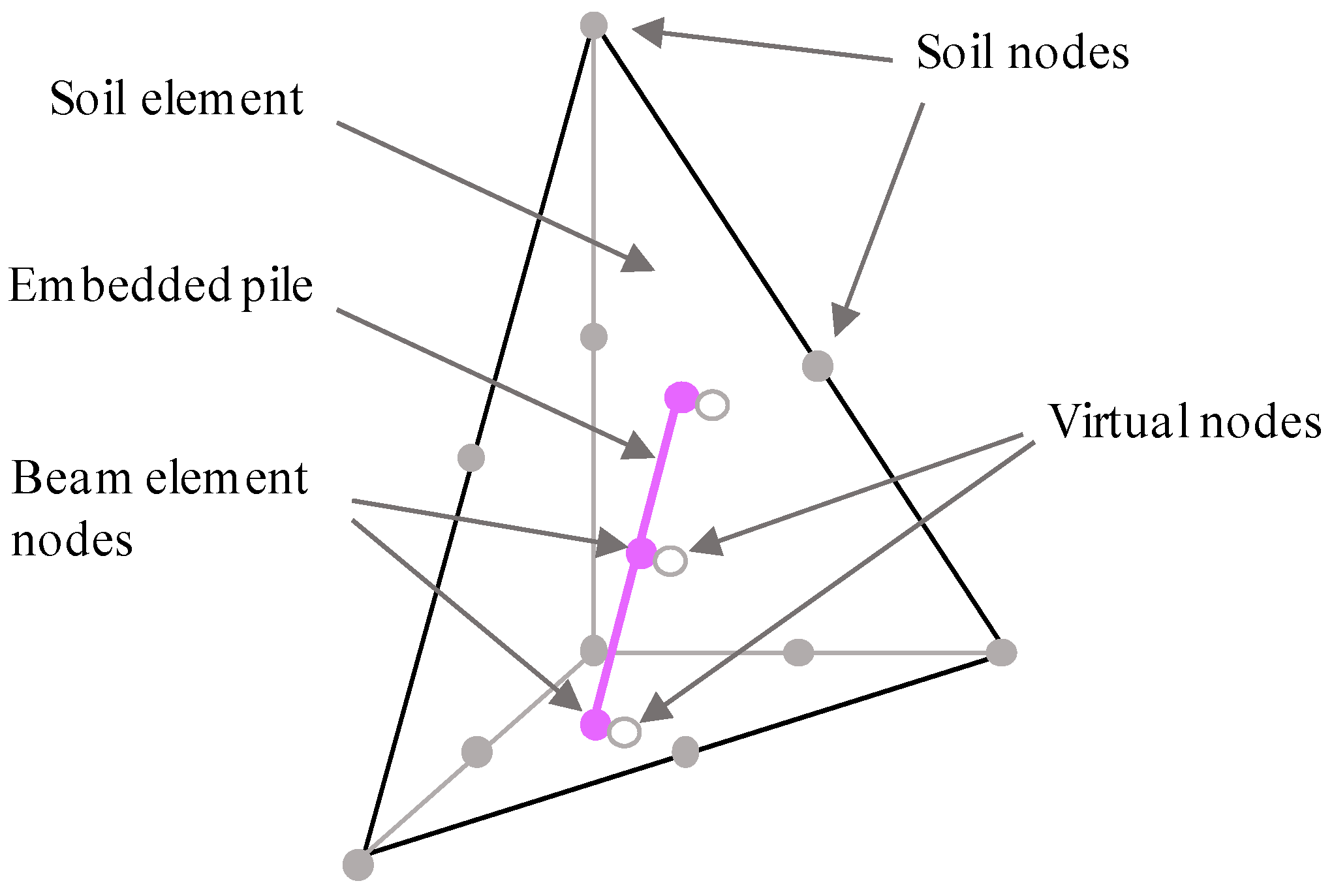
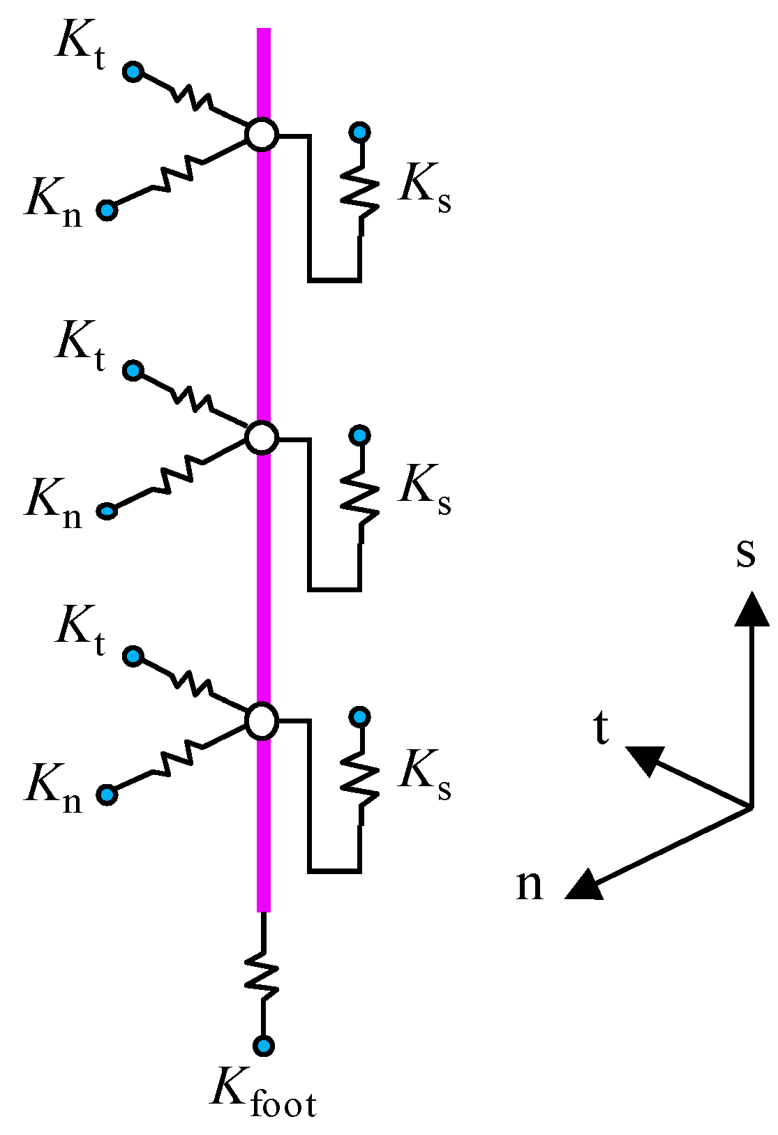
The embedded pile element is a kind of one-dimensional (1D) beam element that does not participate in soil meshing, and can be set up in any position in any direction in the soil mesh. The virtual node can be generated along the body of the pile (Figure 1). The embedded pile interacts with the surrounding soil through embedded interface elements. The bearing capacity of the pile end is simulated using the bottom spring element. The lateral friction and end force of the pile are determined via the relative displacement of pile and soil (shown in Figure 2). Because the embedded pile element does not influence the generation of the soil mesh, compared with the solid pile simulation, the overall number of elements of the model can be significantly reduced and the efficiency of calculation can be improved. The displacement and internal force of the pile can also be quickly generated. Schweiger et al. [24], Tradigo et al. [25], and Engin et al. [30] verified the performance of single-pile foundations, pile group foundations, and pile–raft foundations simulated using the embedded pile element instead of the solid pile element.
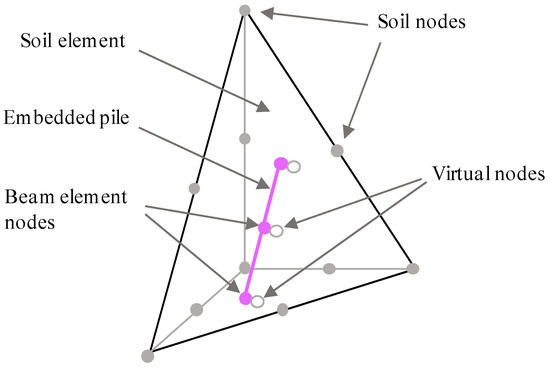
Figure 1.
Embedded pile within a 10-node tetrahedral element.

Figure 2.
Stiffness of the embedded interface elements at the skin of the pile.
2.2.3. Integral Equivalent Method
When the number of piles or the scale of the structure is particularly large (such as hundreds or even thousands of piles), or the structure is complex (e.g., has a basement or consists of multiple buildings), the convergence of the calculation is poor because of the large number of elements, which can easily lead to the appearance of deformed elements, and the complex interactions caused by a large number of interfaces between soil and structure. Methods using the solid pile element and interface, as well as those using the embedded pile element, cannot meet the requirements of the rapid assessment of the soundness of the project in practice in this case.
In this paper, a simplified method based on the equivalent simulation is proposed for a large number of CFG piles, where the vertical reinforcement and soil are regarded as an anisotropic whole, and piles simulated using the embedded pile element or solid element are not needed in the model. Instead, the parameters of the stiffness and strength of the entire strengthened area are replaced by the equivalent settlement value and distribution. The CFG pile is a kind of geopolymer with high bond strength mixed by cement, fly ash, aggregate, and water. Its material composition and mechanical properties are similar to that of ordinary concrete. The material strength of CFG pile is usually determined through the unconfined compressive strength test [31,32]. In calculations for the simulation, the equivalent reinforcement zone is regarded as an anisotropic elastoplastic material. The jointed rock model in PLAXIS was used to model this zone. The main parameters of the jointed rock model in the finite element program were density ρ, cohesion force c, friction angle ϕ, the elastic moduli (E1 and E2) and Poisson’s ratios (v1 and v2) in horizontal and vertical directions, and the shear modulus G2 in the vertical direction in the process of numerical modeling. Density was expressed as the thickness-weighted average value of the density of each layer of soil in the reinforcement zone. The cohesion force could be obtained using the cement strength of the CFG pile. A friction angle of zero was used, Poisson’s ratios in both directions were 0.3, the elastic moduli (E1 and E2) were obtained via back-calculation according to the target settlement value and the horizontal deformation, and the shear modulus G2 was determined by converting E2 and v2.
The integral equivalent method is practical for the three-dimensional numerical analysis of synergetic interaction between the raft of high-rise buildings and the composite foundation formed by a large number of CFG piles. The feasibility and practical application of this method are introduced in the sections below.
3. Comparative Analysis of Working Performance of Pile–Raft System
3.1. Numerical Modeling
3.1.1. Engineering Case Summary
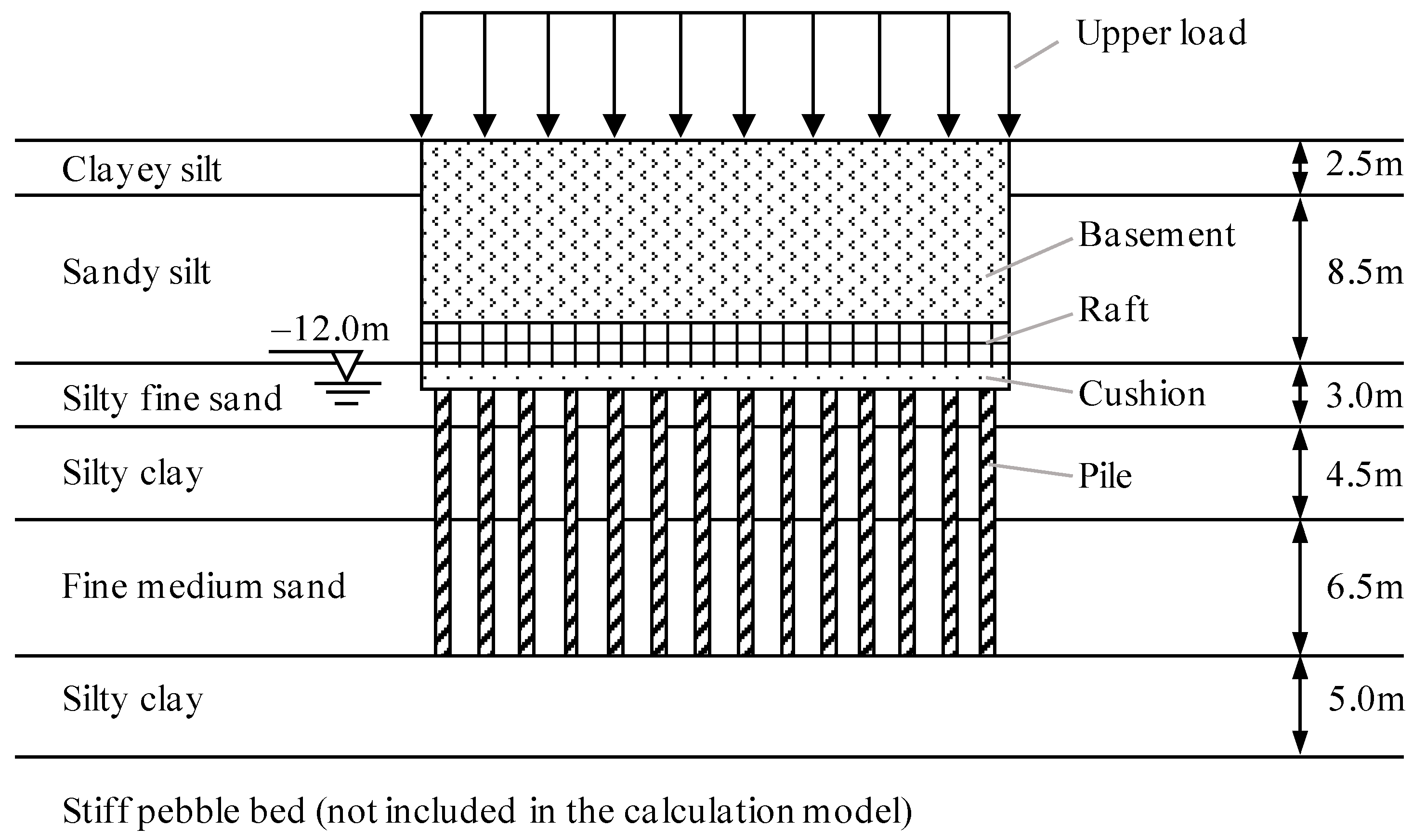
The in situ prospecting data were taken from Beijing, China. The order of in situ soil from top to bottom was as follows: (1) clay silt, (2) sandy silt, (3) silty-fine sand, (4) silty clay, (5) fine-medium sand, and (6) silty clay. The thicknesses of the soil layers were 2.5 m, 8.5 m, 3.0 m, 4.5 m, 6.5 m, and 5.0 m, respectively (shown in Figure 3). There were deep hard pebbles beneath these soil layers. The groundwater depth was 12 m. The in situ case was a high-rise building with a three-floor basement and 17 floors above ground. The excavation depth of the basement foundation was 11 m, and it was supported by a nailing wall of composite soil. The natural foundation could not meet the bearing capacity and settlement requirements of the building, and was stabilized using a CFG pile (pile diameter of 400 mm, pile spacing of 1600 mm, and cement concrete C25) (shown in Figure 4). The thickness of the cushion between the basement and the pile was 200 mm. The load of each floor and basement was approximately 15 kPa, which was converted and applied to the roof of the basement.
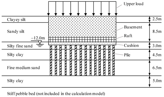
Figure 3.
Schematic profile of calculation model.
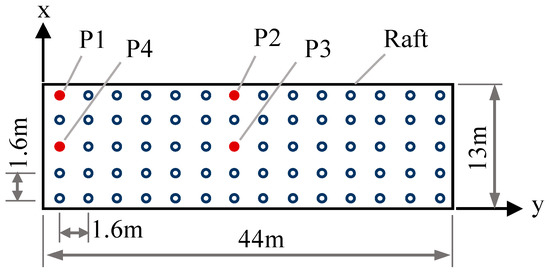
Figure 4.
Schematic profile of calculation model.
3.1.2. Model Building
The 3D numerical model of the structure was created using PLAXIS 3D.
• Model Size
According to the size of the pile–raft foundation and the excavation depth of the basement foundation pit, the length and width of the model were determined to be two times the excavation depth by changing the size and solving the model several times. The stratum depth of the model ranged from the ground to the top of the hard pebbles. The eventual length, width, and height of the model were determined to be 100 m, 80 m, and 30 m, respectively.
• Element Selection
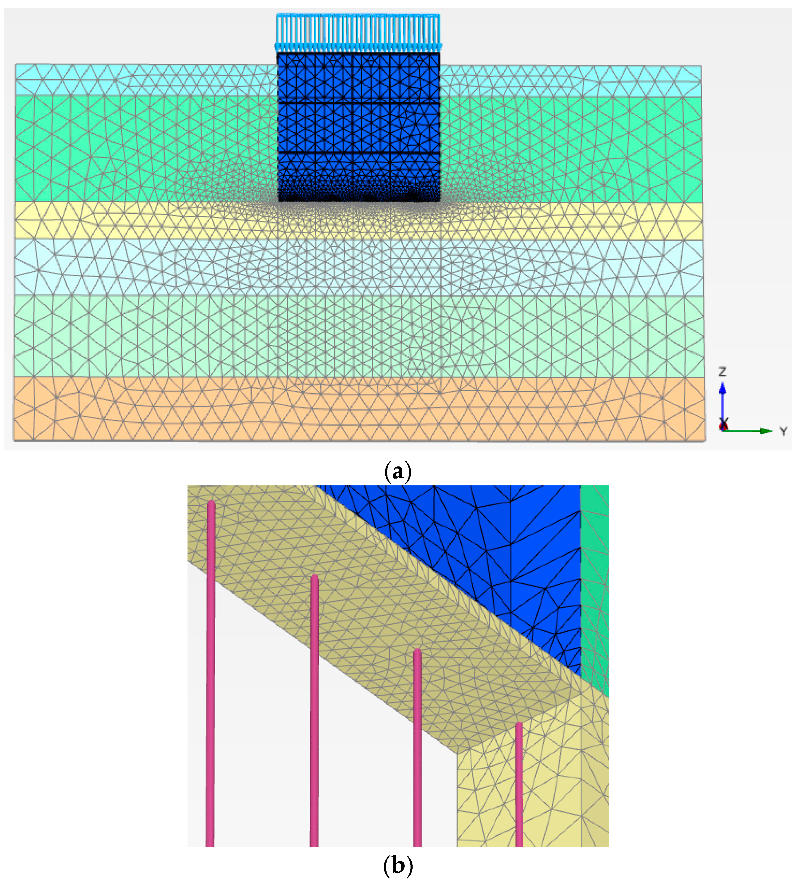
The soil layer and cushion were discretized by a 10-node tetrahedral element. The six-node plate element was used to simulate the basement floor, wall, and raft structure. The three-node beam element was used to simulate the basement pillar. The embedded pile element was used to simulate the CFG pile. The interface was set between the cushion and the basement floor to simulate the interaction between the reinforced concrete floor and the unbound aggregate cushion considering the stiffness difference between them. A zero-thickness interface element was used as the interface element in this study [29], and the relative displacement of the joints on both sides of the interface was allowed to occur. The parameters of the interface in PLAXIS are associated with the parameters of the surrounding soil (i.e., the cushion material in this case) by a reduction coefficient Rinter. In this paper, Rinter was set as 1.0. When the model grid was divided, the distribution of the global element was set to “very fine”, and the soil mesh around the pile–raft foundation was locally refined. The total number of solid elements was more than 100,000. The model mesh is shown in Figure 5.
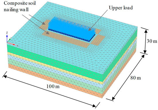
Figure 5.
Three-dimensional (3D) mesh model.
• Material Model and Parameters
The soil and cushion were considered elastoplastic materials in this study. The hardening soil (HS) mode was used, which is suitable for the analysis of mechanical behavior under loading and unloading. The input parameters of the hardening soil (HS) model include secant stiffness in the drained triaxial test , tangent stiffness for oedometer loading , unloading/reloading stiffness , exponential power m, Poisson’s ratio v, cohesion c, and frictional angle ϕ. These parameters were determined via the method provided in the finite element program. and v were estimated empirically, while = , = 3, and m was equal to the default value of 0.5. Other parameters were obtained via the basic geotechnical test, the triaxial test, and the consolidation test [33]. Other settings in PLAXIS 3D were default values of the program. The cushion was simulated by an ideal elastoplastic model following the Mohr–Coulomb criterion. The basement floors, walls, pillars, rafts, and piles were assumed to be in a linear elastic state. Moreover, because this paper focuses on the analysis of building settlement, the reinforcement zone of the composite soil nailing wall during the excavation of the basement’s foundation pit was treated by the equivalent method of increasing the value of the parameters of overall strength and stiffness. The parameters of soil were determined according to survey reports, geotechnical tests, and engineering experience, and those of the structural material were converted according to the structural cross-section and material type, as shown in Table 1 and Table 2.

Table 1.
Physical and mechanical parameters of soil.
Table 2.
Material parameters of structure. CFG—cement/fly ash/gravel.
• Boundary Conditions
The boundary conditions of the model were constrained by conventional static displacement. The upper surface of the model was free along all directions. The lateral side of the model was supported by sliding hinges, which limited horizontal displacement, and it could move freely along the vertical direction. The bottom boundary of the model was fixed along all directions.
3.1.3. Material Parameters of Equivalent Reinforcement Zone
The equivalent reinforcement zone of CFG pile composite foundation was regarded as an anisotropic elastoplastic material and its mechanical behavior was described by using jointed rock model. The model parameters included the stiffness E1 and v1 on the horizontal direction (α1 = 0°) and the stiffness parameter E2 and v2 on the vertical direction (α2 = 90°). The strength of the CFG pile was taken as c = 270 kPa and ϕ = 0°. It is key to determine two sets of stiffness parameters during the numerical simulation using the jointed rock model. In this research, assuming v1 = v2 = 0.35, E1 and E2 were determined by trial calculation. The process was as follows: (1) in order to ensure the accuracy of the calculation for pile and cushion, the single-row pile model was established and the meshes of cushion layer and the soil in a certain range of the body of the pile were locally refined to obtain 5–10 elements around each pile; the model mesh is shown in Figure 6; (2) the material parameters of the equivalent composite foundation (E1 and E2) were acquired by fitting to the vertical deformation (i.e., settlement) and the horizontal deformation outside the pile. Assuming v1 = v2 = 0.3, the first step was to make E1 = E2 to fit the vertical deformation, and then to adjust E1 to fit the horizontal deformation. After that, satisfactory fitting results were obtained by adjusting E2 slightly. After three rounds of aforesaid trial calculation, it was established that E1 = 1.0 × 10⁴ kPa, E2 = 1.2 × 10⁵ kPa, and G2 = 0.5E2/(1 + v2) = 4.62 × 10⁴ kPa.
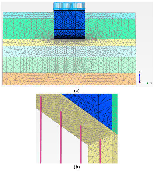
Figure 6.
Model mesh of single-row pile: (a) integral model diagram; (b) partial enlarged detail.
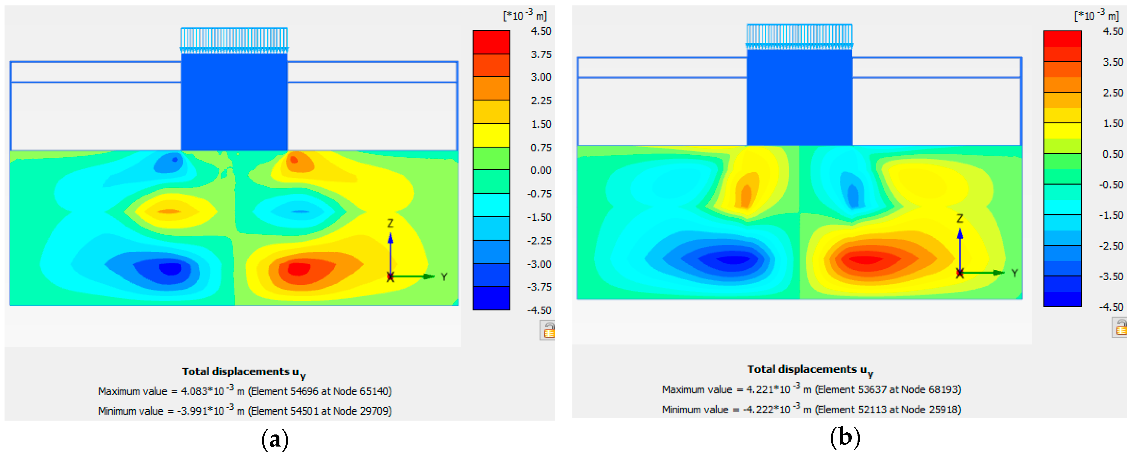
The comparisons of vertical deformation and horizontal deformation of the bottom cushion between the above equivalent model and the embedded pile model are shown in Figure 7 and Figure 8, respectively. It was shown that the numerical results obtained using the equivalent model were very close to those obtained using the embedded pile model, and the equivalent parameters were reasonable.
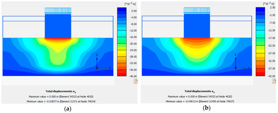
Figure 7.
Comparison of vertical deformation of the bottom cushion: (a) embedded pile model; (b) equivalent reinforcement zone model.

Figure 8.
Comparison of horizontal deformation of the bottom cushion: (a) embedded pile model; (b) equivalent reinforcement zone model.
3.2. Numerical Calculation Scheme
To verify the feasibility of CFG piles in reinforcing the foundations of high-rise buildings, three schemes for the numerical calculation of piled raft foundations were used as follows:
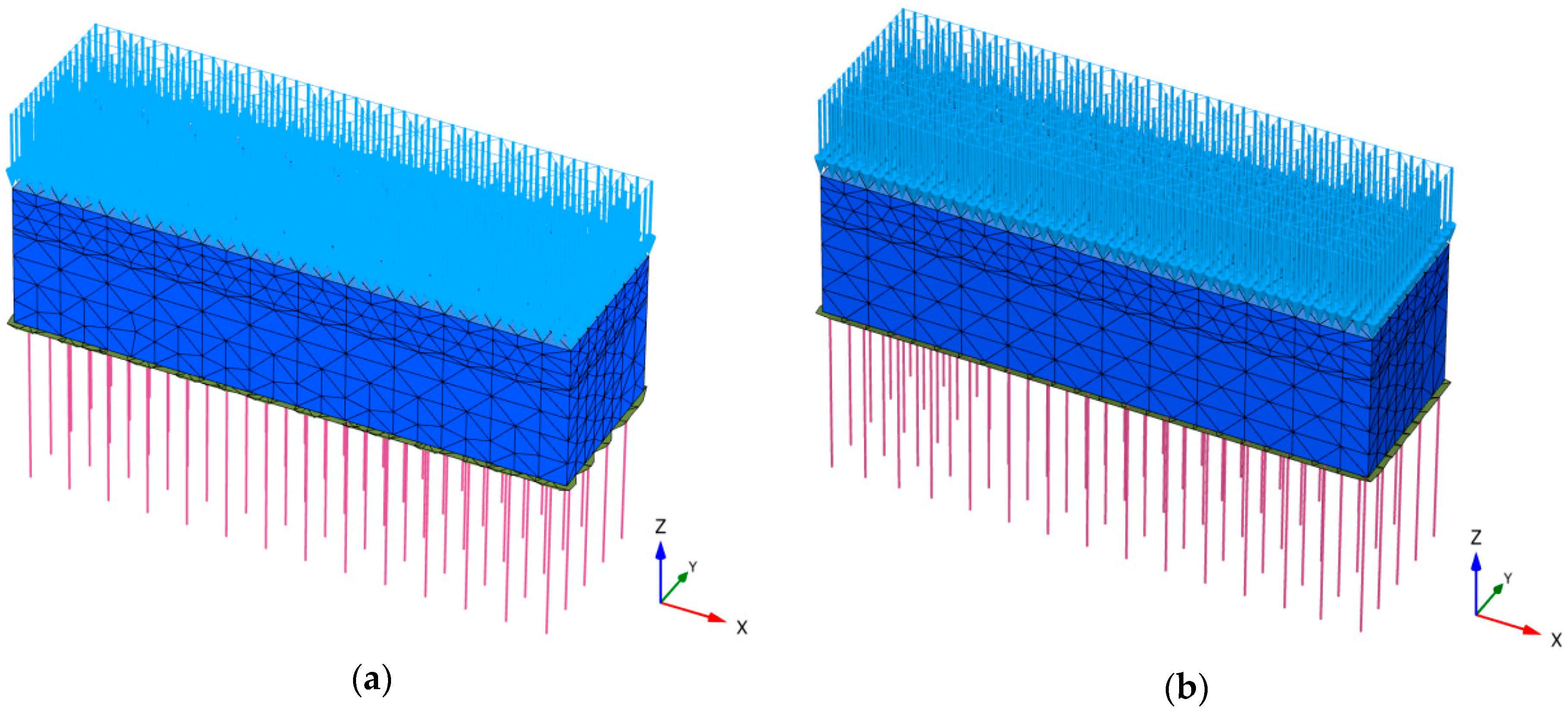
Scheme 1: Raft + concrete-bored piles. The top of the pile was rigidly connected to the raft; the length of pile was 14 m; the diameter was 0.8 m; and the spacing between piles was 3.2 m (shown in Figure 9a).

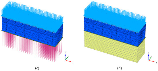
Figure 9.
Pile–raft basement models for different simulation schemes: (a) Raft + concrete-bored piles (pile simulated by embedded pile element); (b) raft + cushion+ concrete-bored piles (pile simulated by embedded pile element); (c) raft + cushion + cement/fly ash/ gravel (CFG) piles (pile simulated by embedded pile element); (d) raft + equivalent reinforcement zone.
Scheme 2: Raft + cushion + concrete-bored piles. The thickness of the cushion was 200 mm; and the parameters of the pile were the same as above (shown in Figure 9b).
Scheme 3: Raft + cushion + CFG piles. The length of the pile was 14 m; the diameter was 0.4 m; and the spacing between piles was 1.6 m (shown in Figure 9c).
Moreover, based on Scheme 3 and the integral equivalent method proposed in Section 2.2.3, Scheme 4 was developed.
Scheme 4: Raft + equivalent reinforcement zone. The cushion was incorporated into the equivalent reinforcement zone (shown in Figure 9d).
The simulated procedure of constructing calculations for the above four schemes was as follows: (1) applying gravity to calculate the initial stress field of soil as initial state; (2) excavating the foundation pit, activating the reinforcement zone of the soil nailing wall, and calculating to convergence; (3) constructing piles below the bottom of the foundation pit, activating the embedded pile element (for Schemes 1, 2, and 3) or improving the equivalent parameters of the reinforcement zone (for Schemes 4), and calculating to convergence; (4) constructing the raft and basement structures, applying the upper load, activating the corresponding structural element, interface element, and surface load, and calculating to convergence; and (5) backfilling around the basement, and calculating to convergence.
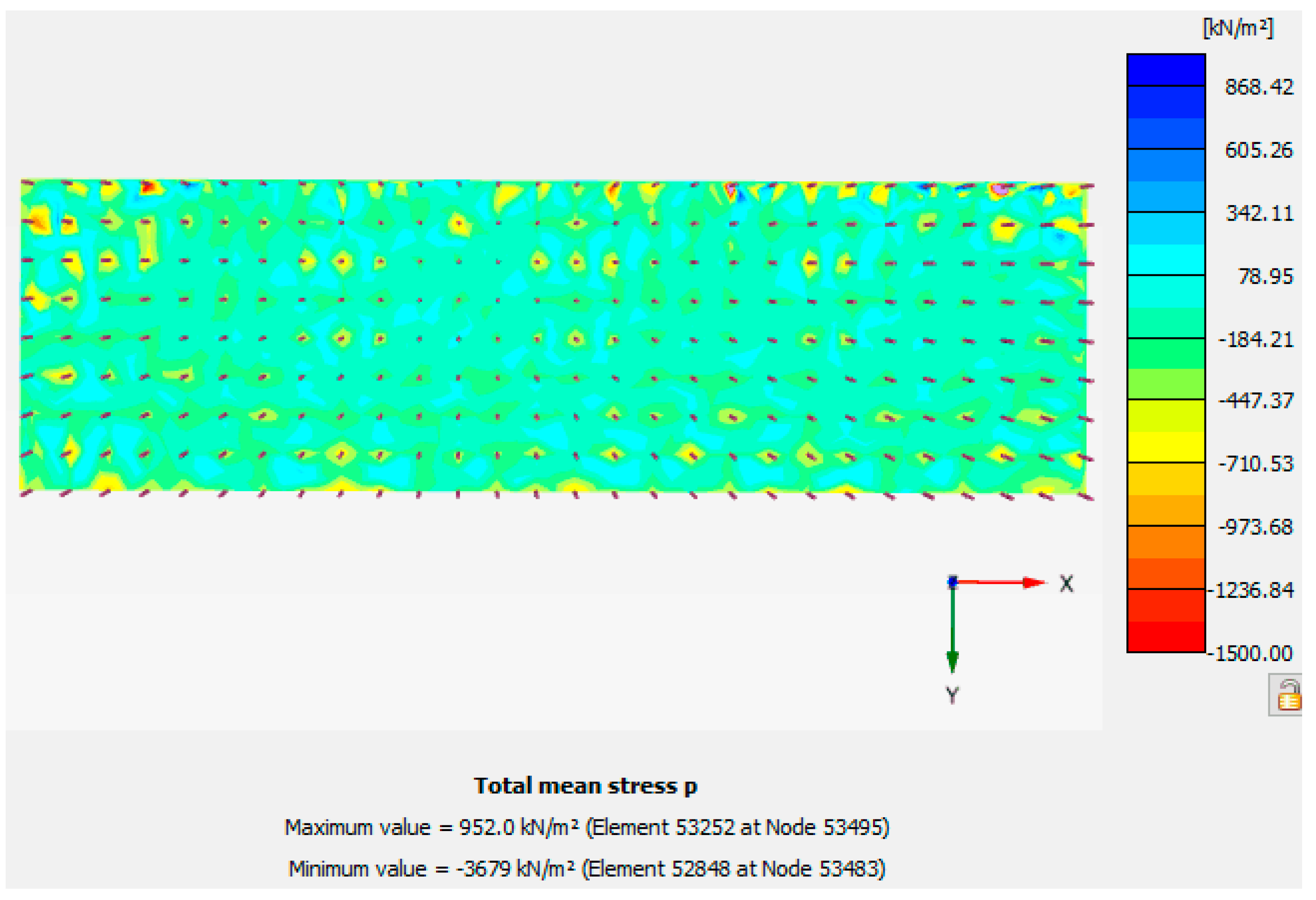
In order to improve the accuracy of the calculation of Scheme 2, a special simulation on the cushion layer was carried out by means of refining the finite element mesh of the cushion, so that the stress concentration on top of the pile could be properly reflected. It can be seen that the total mean stress p of the cushion layer was uniformly distributed, as shown in the Figure 10, which effectively avoided the excessive concentration of local stress on top of the pile, ensuring the accuracy of the calculation.

Figure 10.
Principal stress nephogram in the cushion layer.
3.3. Results and Discussion
3.3.1. Performance of raft
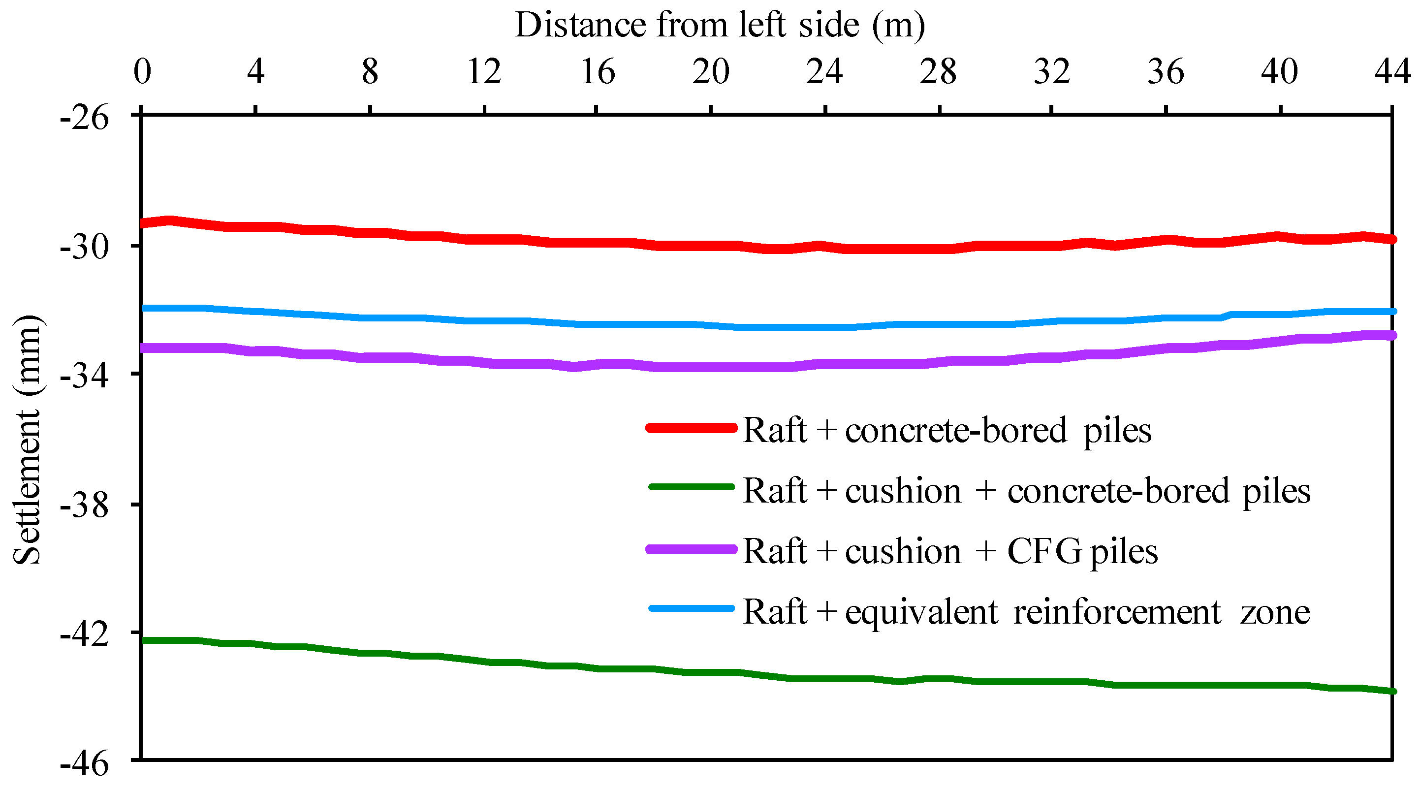
Figure 11 shows a comparative diagram of the settlement curves of the longitudinal central section of the raft of the four simulation schemes. The maximum settlement Smax of Scheme 2 was the largest (Smax2 = −43.8 mm), that of Scheme 1 was the smallest (Smax1 = −30.43 mm), and those of Schemes 3 and 4 were slightly larger than that of Scheme 1. It is evident from the settlement distribution in Figure 8 that Smax2 of Scheme 2 appeared at the right end of the raft, and the settlement curves of the other three schemes were approximately symmetrically distributed (i.e., Smax appeared near the center of the raft). The settlement distributions of the raft in the four schemes were uniform. The differences between the maximum and minimum settlements of the raft under each scheme were within 2 mm of one another.
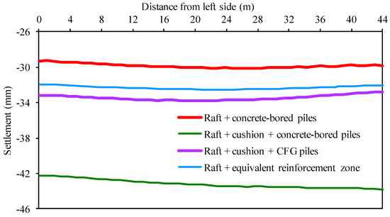
Figure 11.
Settlement curve of the longitudinal central section of the raft under the four simulation schemes.
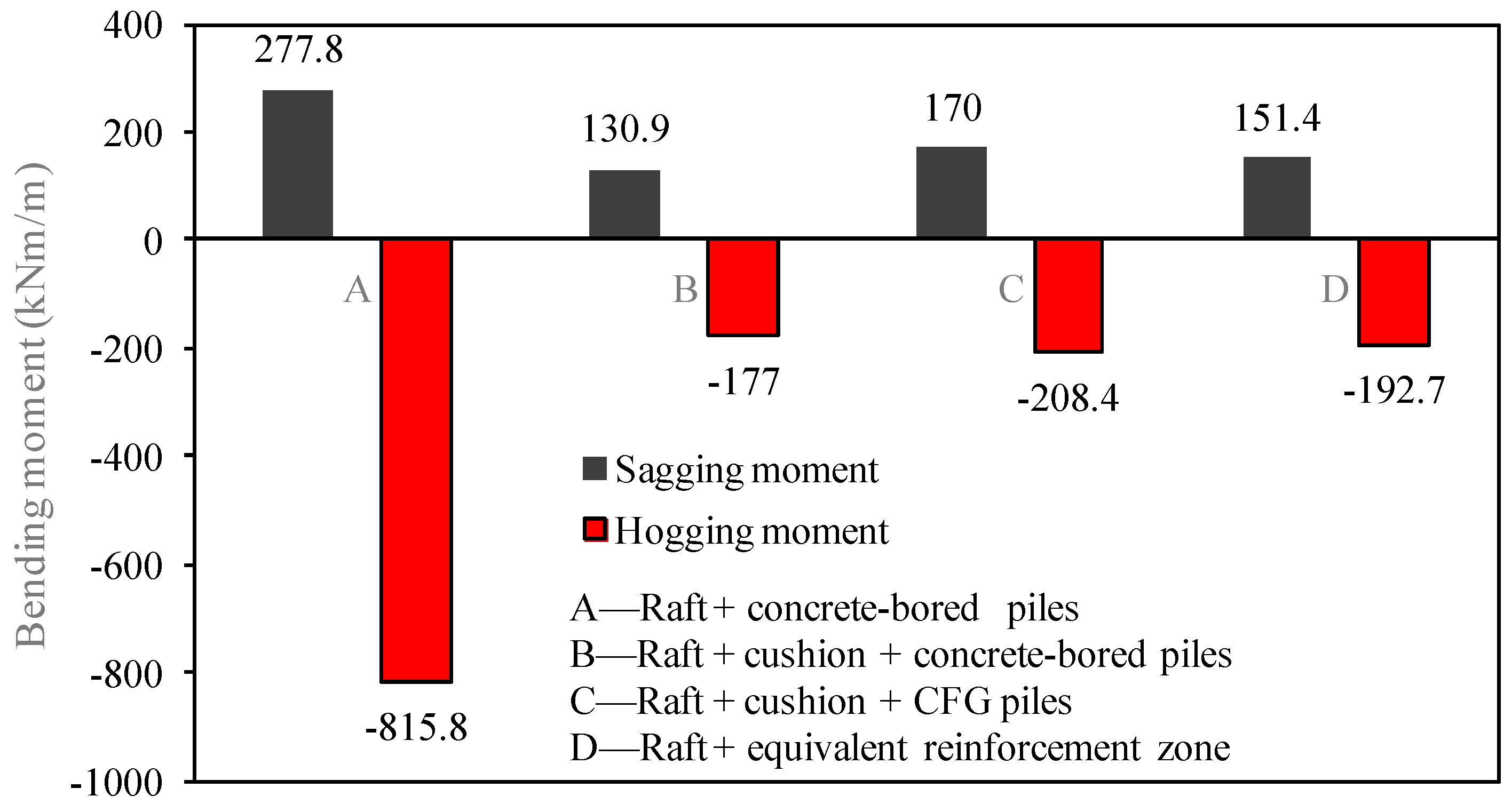
In Scheme 1, the bored piles were rigidly connected to the raft, and the settlement of the raft was the smallest. However, the joint between the top of the pile and the raft produced a relatively large bending moment. Figure 12 shows a comparative histogram of the extrema of the bending moments of the raft plate of the four calculation schemes, in which the value of the hogging moment of the raft in Scheme 1 Mmin1 = −815.8 kNm/m, and the extremum of the moment of the raft plate of Scheme 1 was much higher than those in the other three schemes.
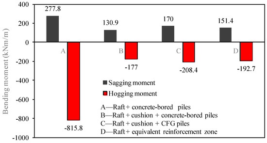
Figure 12.
Comparison of extrema of the bending moments of the raft under the four simulated schemes.
In Scheme 2, there was a cushion between the bored pile and the raft. Compared with the composite foundation consolidated by CFG piles in Scheme 3, the spacing of the bored pile in Scheme 2 was large, and a greater load was shared by the soil among the piles, which produced a greater compression deformation in Scheme 2. Moreover, because the stiffness of the bored pile was higher than those of the upper cushion and the underlying soil, a larger deformation was caused at the top and bottom of the pile under the action of the upper load, which had a certain effect on raft settlement. At the same time, the extremum of the bending moment of the raft was greatly reduced, i.e., the Mmin2 of Scheme 2 was 78.3% lower than the Mmin1 of Scheme 1.
CFG piles were used in Scheme 3, where the settlement of the raft was close to that of Scheme 3. This shows that using piles with relatively low strength and setting a cushion layer with the appropriate thickness can give more play to the bearing capacity of the soil between the piles to control the settlement of the buildings well. At the same time, the bending moment of the raft foundation was clearly lower than that of the rigid connection of the pile–raft foundation. The pile–raft foundation with the relative moment of the raft plate was significantly smaller than Mmin1, by 74.5%, i.e., Mmin3 of Scheme 3 was 74.5% lower than Mmin1 of Scheme 1.
The reinforcement zone of the CFG pile in Scheme 4 was treated using the integral equivalent method. The difference between the maximum settlement of Scheme 4 and that of Scheme 3 was approximately 3.8%. The differences between the positive and negative bending moments of Schemes 4 and 3 were 10.9% and 7.5%, respectively. This indicates that the settlement and internal force obtained using the integral equivalent treatment method were similar to those obtained using the embedded pile simulation.
3.3.2. Performance of Piles
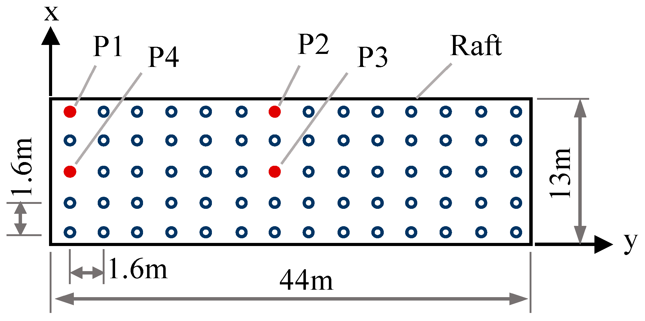
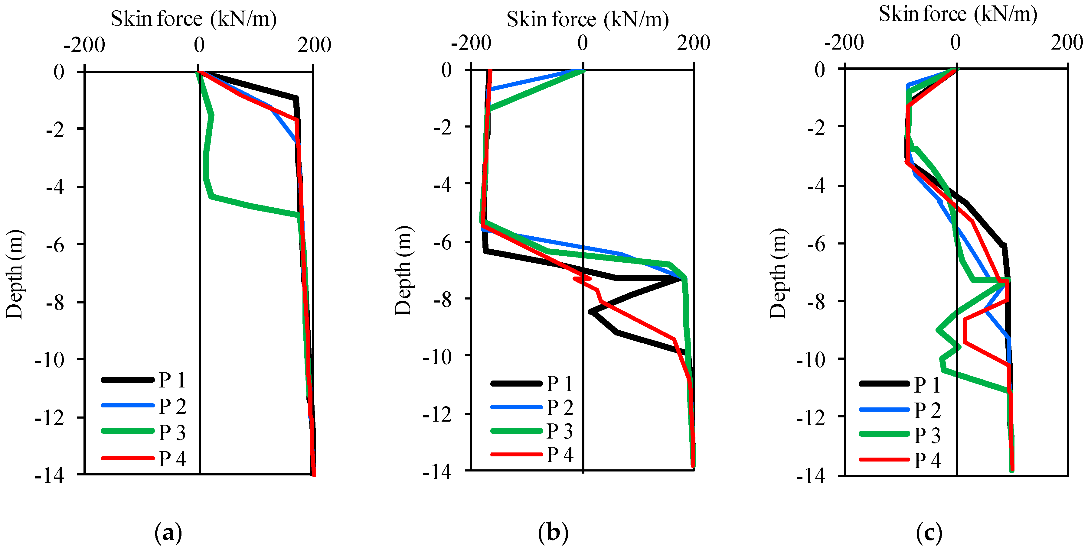
Based on the models in Schemes 1, 2, and 3, the embedded pile element was used to simulate the pile, and the axial force and lateral friction distribution of P1–P4 (shown in Figure 4) were analyzed, as shown in Figure 13 and Figure 14.
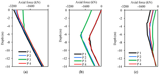
Figure 13.
Distribution of the axial force of the pile: (a) raft + bored pile; (b) raft + cushion + bored pile; (c) raft + cushion + CFG pile.
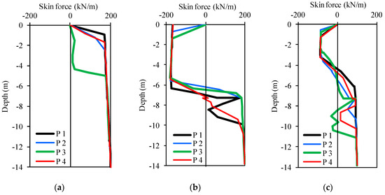
Figure 14.
Lateral frictional distribution of the pile: (a) raft + bored pile; (b) raft + cushion + bored pile; (c) raft + cushion + CFG pile.
It is clear from Figure 13 that the distributions of the axial forces of the pile in the three simulation schemes were different. In Scheme 1, the axial force of the pile was larger in the shallow part of the pile and smaller in the deep part, which was approximately linear with depth. The axial force of the pile in Scheme 2 was represented by a broken line with depth, and the axial force in the middle of the pile was large and the axial force at both ends was small. In Scheme 3, the distribution of the axial force of the pile had an approximately arched shape, the axial force was larger in a certain range of the middle and upper parts of the length of the pile, and the axial force was approximately linear in the range of nearly one quarter of its length to the top or bottom of the pile. This result was consistent with the results of the analysis by Ata et al. [21].
By comparing the axial force of the pile in different positions (P1, P2, P3, and P4), it is clear that the distribution of the axial forces of the four piles in Scheme 1 was roughly the same, that of the central pile (P3) was slightly different from the side piles (P2 and P4) and the angular pile (P1). The axial force was larger from the top of the pile to a certain depth, and then decreased linearly with increasing depth. In Scheme 2, the distributions of the axial forces of P1 and P4 were similar, and those of P2 and P3 were similar, while the axial forces of P1 and P4 were higher than those of P2 and P3. In Scheme 3, the axial force of P1 was the largest and that of P3 was the smallest, while the axial forces of P2 and P4 were between those of the former two piles and had similar distributions.
Figure 14 shows the distribution of the lateral friction of the pile in the abovementioned three simulation schemes. The lateral friction of the pile in Scheme 1 was significantly different from those of Schemes 2 and 3 with the cushion, and there was no negative friction along the length of the pile in Scheme 1 because of the synchronous subsidence of the bored pile and raft when they were rigidly connected. Because there was a certain thickness of the cushion on top of the pile in Schemes 2 and 3, the cushion was compressed and sunken due to the load applied by the raft, the top of the pile was pierced into the cushion, the soil between the piles was compressed and deformed under pressure from the cushion, and the displacement of the pile was downward. Therefore, negative friction appeared in a certain range below the top of the pile in Schemes 2 and 3, and then became positive as depth increased. It can be concluded that the presence of the cushion between the top of pile and the raft determines the differences in the mechanism of the pile–soil–raft interaction [21]. Moreover, the depth of distribution of the negative lateral friction of the pile in Scheme 2 was close to 6 m, which was approximately two times the distribution of the negative lateral friction in Scheme 3 in terms of depth. This indicates that the relative displacement between the pile and soil in the foundation stabilized using the CFG pile with high stiffness was larger than that of the CFG pile with relatively low stiffness. From the point of view of the pile–soil–cushion–raft interaction mechanism, the above reasons also explain why the raft settlement in Scheme 2 was larger.
4. Numerical Calculation Case
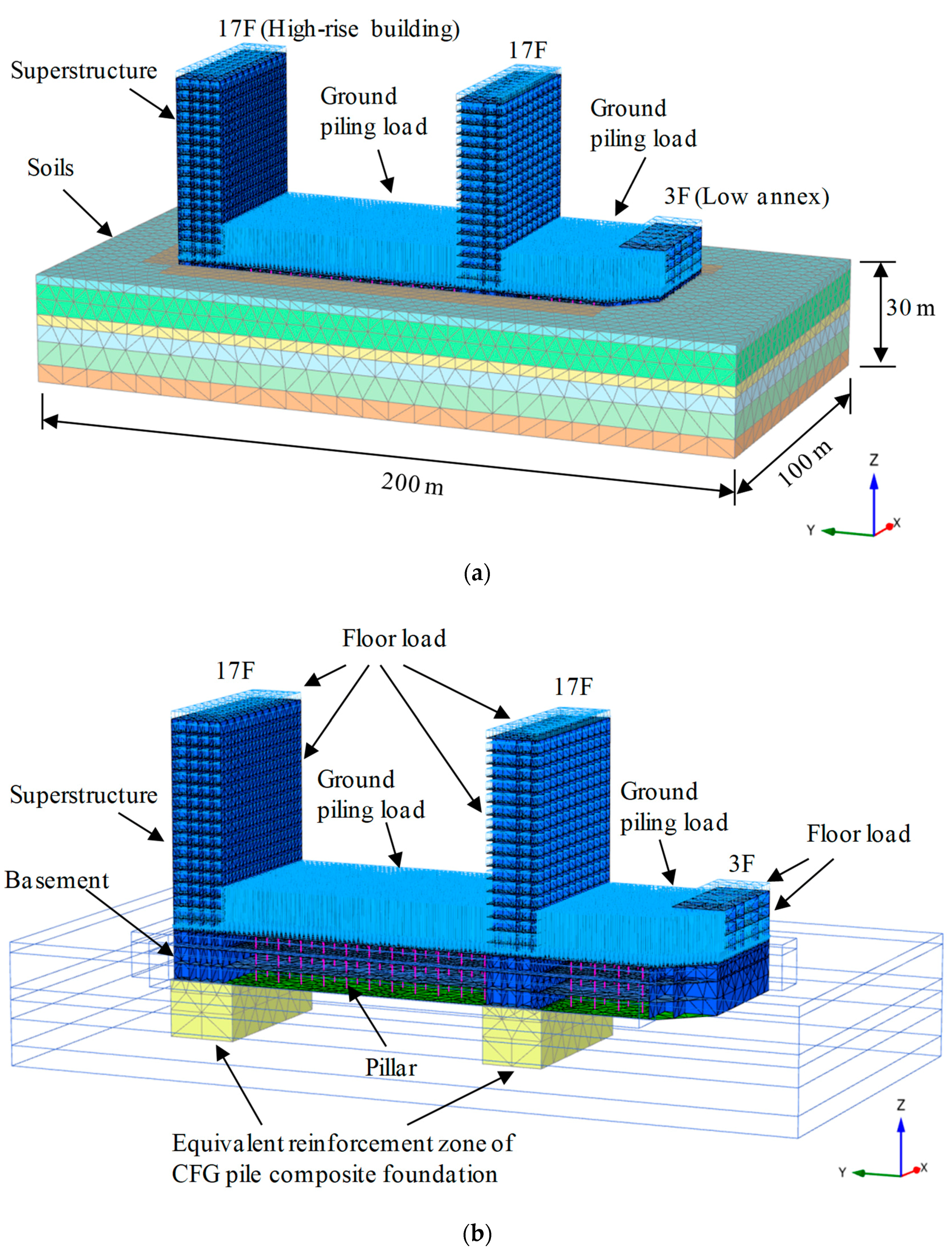
In order to further illustrate the applicability of the equivalent simulation method proposed in this research, this method was applied to high- and low-rise buildings in Beijing, China, as a numerical calculation case.
The entire raft was used as the foundation of the complex of buildings. CFG piles were used to reinforce the foundation of the high-rise, and the natural foundation was used in the basement and the low annex. The effect of the settlement control of the raft was analyzed using the equivalent simulation method of the strengthened zone mentioned above.
The modeling method used was the same as in the previous section. The integral equivalent simulation method was used to simulate the reinforcement effect of the CFG piles by increasing the strength and stiffness parameters of the reinforcement zone. Moreover, to consider the influence of the stiffness of the superstructure on the settlement of the raft, a model of the superstructure was created using a slab element, and a floor load of 15 kPa was applied to each floor. The roof load of the underground garage was 90 kPa. The overall size of the model was 100 m × 200 m × 30 m (x × y × z), and it was divided into 73,437 10-node tetrahedral elements and 162,202 nodes, which included 41,675 plate elements, 450 beam elements, and 1698 interface elements. Figure 15 shows the meshes of the 3D model of the foundation reinforcement of the high-rise buildings. The model parameters of the soil are shown in Table 1. The parameters of the beam element of the basement pillar were as follows: elasticity modulus E = 3 × 10⁷ kPa, sectional area A = 0.36 m2, and moment of inertia of area I = 0.01 m4. The model parameters of the plate element were as follows: thickness of the raft of the foundation of high-rise structure d = 0.8 m, thickness of the other raft d = 0.5 m, elasticity modulus E = 3.25 × 10⁷ kPa, thickness of foundation raft d = 0.8 m, and thickness of other raft d = 0.5 m. The model parameters of the superstructure were as follows: thickness of the wall of superstructure d = 0.3 m, floor thickness d = 0.2, and elasticity modulus of the floor E = 3 × 10⁷ kPa. The equivalent parameters of the reinforced zone of the composite foundation were as follows: elasticity modulus E1 = 1.0 × 10⁴ kPa, E2 = 1.2 × 10⁵ kPa, Poisson’s ratio v1= v2 = 0.3, G2 = 4.62 × 10⁴ kPa, cohesion force c = 270 kPa, and ϕ = 0°.
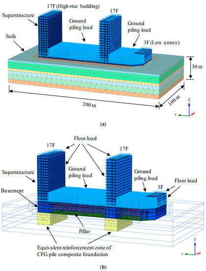
Figure 15.
3D model for foundation reinforcement of high-rise buildings: (a) integral mesh; (b) superstructure, basement, and high-rise foundation reinforcement area grid.
The construction processes were simulated as follows: (1) calculation of initial stress field; (2) excavation of foundation pit; (3) construction of CFG pile using equivalent treatment method to improve the parameters of the strengthened zone; (4) construction of basement by considering the temporary load on the roof of the basement; and (5) construction of superstructure by applying a load on each floor.
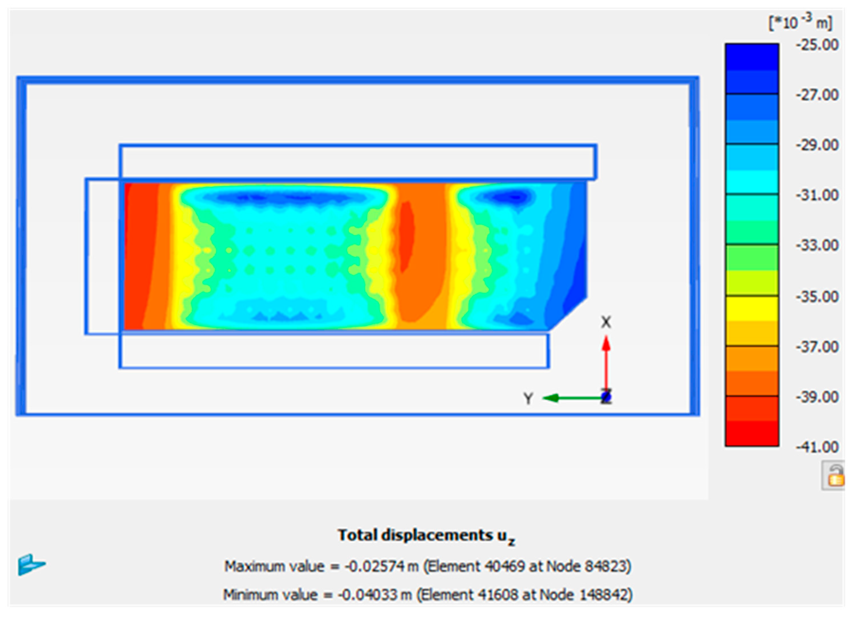
Figure 16 and Figure 17 show the settlement nephogram in the entire raft and the settlement distribution in the center section of the raft of the high-rise buildings, respectively. Following CFG pile reinforcement, the settlement of the high-rise building was controlled to within 40 mm, the maximum settlement of the raft slab was 40.3 mm, and the maximum differential settlement was approximately 0.5%, which was lower than the differential settlement control value of 2% [28]. According to the theoretical method mentioned in the foregoing, the maximum settlement of the raft was 20.3 mm and the maximum differential settlement was 0.8%, similar to the results of settlement obtained by the 3D numerical simulation in this section. The results show that the settlement of the foundations of the high-rise building strengthened using the CGF pile, and the natural soils directly used in the foundation of the annex and underground garages met the requirements of settlement control.

Figure 16.
Settlement nephogram in the raft of high-rise buildings.
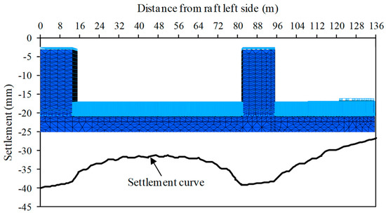
Figure 17.
Settlement distribution in the center section of the raft of high-rise buildings.
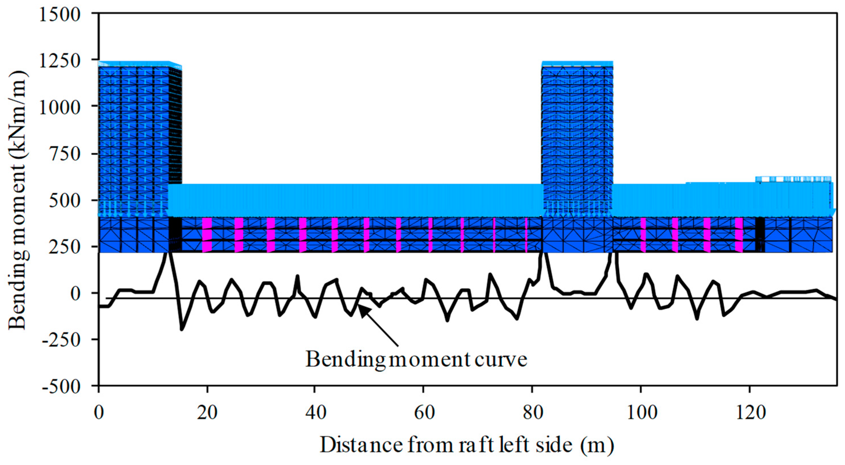
Figure 18 and Figure 19 show the bending moment nephogram of the entire raft and the distribution of moment in the center section of the raft of the high-rise buildings, respectively. As shown in the figures, the distribution of the bending moment of the entire raft plate of the high-rise buildings was uniform, and the extrema of positive and negative moment were smaller at 610.2 kNm/m and −262.5 km/m, respectively. This shows that a reasonable internal force of the raft plate can be obtained using the proposed foundation treatment method, which is more economical for raft design. Moreover, the numerical results provide a design reference for the internal force to calculate raft structures.
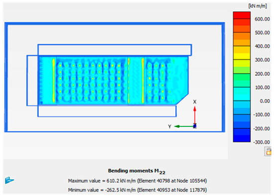
Figure 18.
Nephogram of the bending moment in the entire raft of the high-rise buildings.

Figure 19.
Distribution of moment in the center section of the raft of the high-rise buildings.
5. Conclusions
In this paper, the mechanical mechanism and settlement performance of a non-contact pile–raft foundation were analyzed using the 3D finite element method, and the effect of the composite foundation of CFG pile on controlling the settlement of a high-rise building was studied. To overcome the difficulty of poor convergence caused by the large number of piles, an equivalent simulation method for the reinforcement zone was proposed. Based on the calculation and analysis in this study, the following conclusions can be stated:
(1) After setting a cushion between the pile and the raft plate, the internal force of the raft can be adjusted effectively and the extremum of its moment can be reduced. However, when the strength and stiffness of the pile are high, the entire settlement of the raft can be increased because of the large deformation at the top and bottom of the pile.
(2) The settlement can be controlled well using a CFG pile with relatively low strength to reinforce the foundation. The axial force and the bending moment of the raft of the CFG pile were clearly lower than those of the bored pile in the foundation.
(3) When the number of piles was large, the reinforcement zone (including the soil and the pile) can be regarded as an anisotropic elastoplastic material. Once the integral strength and stiffness parameters of the reinforcement zone were given properly, the settlement and bending moment of the raft obtained using the integral equivalent simulation method were more or less consistent with those obtained using the embedded pile simulation method.
(4) The equivalent simulation method of the reinforced zone is suitable for buildings on a large scale, with a large number of structural units and complex synergetic interactions between soil and structure. It is an effective and practical method to quickly evaluate the settlement control effect of foundation treatment schemes. It should be emphasized that the selection of equivalent parameters in the reinforcement zone depends on experience and trial calculations, and needs to be systematically studied in the future.
Author Contributions
All the authors were involved collaboratively in the paper drafting and review. In particular, X.N. and Y.Y. conceived and designed the research; X.N. took care of the FE modeling and parametric studies, while Y.S. implemented the simplified analytical model; X.N. and Y.S. performed the numerical analyses; X.N. and Y.H. analyzed the data and prepared the manuscript; H.Z. optimized the numerical model. Y.Y. supervised the overall project.
Funding
This research was funded by the Shanxi Province Natural Science Foundation (201701D121068), the Research Plan of Shanxi Province Department of Transportation in China (2016-1-7), the China Postdoctoral Science Foundation (2016M591044), the National Basic Research Program of China (973 Program, 2014CB047001), and the Innovation and Entrepreneurship Training Program for Undergraduate in Shanxi Province, China (201810108034).
Acknowledgments
The authors thank Zhixiang Liu, from the China Institute of Building Standard Design and Research, for his support and help in numerical modeling.
Conflicts of Interest
The authors declare no conflicts of interest.
References
- Davis, E.H.; Poulos, H.G. The analysis of piled raft systems. Aust. Geotech. J. 1972, 2, 21–27. [Google Scholar]
- Giretti, D. Modeling of Piled Raft Foundations in Sand. Ph.D. Dissertation, University of Ferrara, Emilia-Romagna, Italy, 2010. [Google Scholar]
- Wong, I.H.; Chang, M.F.; Cao, X.D. Raft foundations with disconnected settlement-reducing piles. In Design Applications of Raft Foundations; Hensley, J.A., Ed.; Tomas Telford: London, UK, 2000; pp. 154–196. [Google Scholar]
- Li, N.; Han, X. Numerical tests on the mechanism of the cushion in composite foundation. Rock Soil Mech. 2000, 21, 10–15. [Google Scholar] [CrossRef]
- Shahu, J.T.; Madhav, M.R.; Hayashi, S. Analysis of soft ground-granular pile-granular mat system. Comput. Geotech. 2000, 27, 45–62. [Google Scholar] [CrossRef]
- He, J.; Hong, B.; Qiu, G. Research on cushion action mechanism of CFG pile composite foundation for expressway. Rock Soil Mech. 2004, 25, 1663–1666. [Google Scholar] [CrossRef]
- Liang, F.; Li, J.; Chen, L. Optimization of composite piled raft foundation with varied rigidity of cushion. In Proceedings of the Sessions of the GeoShanghai Conference, Shanghai, China, 6–8 June 2006; American Society of Civil Engineers: Reston, VA, USA, 2006; pp. 29–34. [Google Scholar] [CrossRef]
- Cao, X.D.; Wong, I.H.; Chang, M.F. Behavior of model rafts resting on pile-reinforced sand. J. Geotech. Geoenviron. Eng. 2004, 130, 129–138. [Google Scholar] [CrossRef]
- El Sawwaf, M. Experimental study of eccentrically loaded raft with connected and unconnected short piles. J. Geotech. Geoenviron. Eng. 2010, 136, 1394–1402. [Google Scholar] [CrossRef]
- Fioravante, V.; Giretti, D. Contact versus noncontact piled raft foundations. Can. Geotech. J. 2010, 47, 1271–1287. [Google Scholar] [CrossRef]
- Fioravante, V. Load transfer from a raft to a pile with an interposed layer. Geotechnique 2011, 61, 121–132. [Google Scholar] [CrossRef]
- Rasouli, H.; Azizkandi, A.S.; Baziar, M.H.; Modarresi, M.; Shahnazari, H. Centrifuge modeling of non-connected piled raft system. Int. J. Civ. Eng. 2015, 13, 114–123. [Google Scholar]
- Zhu, X.J. Analysis of the load sharing behaviour and cushion failure mode for a disconnected piled raft. Adv. Mater. Sci. Eng. 2017, 2017. [Google Scholar] [CrossRef]
- Liu, K.; Xie, X.; Liu, H. Performance of rigid-flexible-pile foundation with cushion. Proc. Inst. Civ. Eng. Geotech. Eng. 2010, 163, 221–227. [Google Scholar] [CrossRef]
- Zhang, Z.M.; Zhang, Q.Q. Field test on composite foundation incorporating flexible and rigid piles. Adv. Mater. Res. 2011, 168–170, 1140–1144. [Google Scholar] [CrossRef]
- Liang, F.Y.; Chen, L.Z.; Shi, X.G. Numerical analysis of composite piled raft with cushion subjected to vertical load. Comput. Geotech. 2003, 30, 443–453. [Google Scholar] [CrossRef]
- Zheng, J.J.; Abusharar, S.W.; Wang, X.Z. Three-dimensional nonlinear finite element modeling of composite foundation formed by CFG lime piles. Comput. Geotech. 2008, 35, 637–643. [Google Scholar] [CrossRef]
- Sharma, V.J.; Vasanvala, S.A.; Solanki, C.H. Behaviour of load-bearing components of a cushioned composite piled raft foundation under axial loading. Slovak J. Civ. Eng. 2014, 22, 25–34. [Google Scholar] [CrossRef]
- Tradigo, F.; Pisano, F.; Di Prisco, C.; Mussi, A. Non-linear soil-structure interaction in disconnected piled raft foundations. Comput. Geotech. 2015, 63, 121–134. [Google Scholar] [CrossRef]
- Rasouli, H.; Ghalesari, A.T.; Modarresi, M.; Hasanzadeh, A. Numerical study of non-contact piled raft interaction under static loads. In Proceedings of the 5th International Conference on Civil Engineering and Urban Planning (CEUP2016), Xi’an, China, 23–26 August 2016; Mebarki, A., Ed.; World Scientific: Beijing, China, 2017; pp. 750–762. [Google Scholar] [CrossRef]
- Eslami, A.; Veiskarami, M.; Eslami, M.M. Study on optimized piled-raft foundations (PRF) performance with connected and non-connected piles-three case histories. Int. J. Civ. Eng. 2012, 10, 100–111. [Google Scholar]
- Ata, A.; Badrawi, E.; Nabil, M. Numerical analysis of unconnected piled raft with cushion. Ain Shams Eng. J. 2015, 6, 421–428. [Google Scholar] [CrossRef]
- Sadek, M.; Shahrour, I. A three-dimensional embedded beam element for reinforced geomaterials. Int. J. Numer. Anal. Methods Géoméch. 2004, 28, 931–946. [Google Scholar] [CrossRef]
- Tschuchnigg, F.; Schweiger, H.F. The embedded pile concept–Verification of an efficient tool for modelling complex deep foundations. Comput. Geotech. 2015, 63, 244–254. [Google Scholar] [CrossRef]
- Tradigo, F.; Pisano, F.; di Prisco, C. On the use of embedded pile elements for the numerical analysis of disconnected piled rafts. Comput. Geotech. 2016, 72, 89–99. [Google Scholar] [CrossRef]
- Zhao, M.H.; Zhang, L.; Yang, M.H. Settlement calculation for long-short composite piled raft foundation. J. Cent. South Univ. Technol. 2006, 13, 749–754. [Google Scholar] [CrossRef]
- Zhang, H.; Shi, M.L. Mechanical performance of settlement-reducing pile foundation with cushion. Adv. Mater. Res. 2012, 368, 2545–2549. [Google Scholar] [CrossRef]
- Ministry of Housing and Urban–Rural Development of the People’s Republic of China. GB 50007-2011 Code for Design of Building Foundation; China Architecture & Building Press: Beijing, China, 2011.
- Goodman, R.E.; Taylor, R.L.; Brekke, T.L. A model for the mechanics of jointed rock. J. Soil Mech. Found. Div. 1968, 94, 18–43. [Google Scholar]
- Engin, H.K.; Septanika, E.G.; Brinkgreve, R.B.J.; Bonnier, P.G. Modelling piled foundation by means of embedded piles. In Proceedings of the 2nd International Workshop on Geotechnics of Soft Soils, Glasgow, Scotland, 3–5 September 2008; Taylor & Francis Group: London, UK, 2009; pp. 131–139. [Google Scholar] [CrossRef]
- Mohammadinia, A.; Arulrajah, A.; Sanjayan, J.; Disfani, M.M.; Bo, M.W.; Darmawan, S. Strength development and microfabric structure of construction and demolition aggregates stabilized with fly ash–based geopolymers. J. Mater. Civ. Eng. 2016, 28, 04016141. [Google Scholar] [CrossRef]
- Mohammadinia, A.; Arulrajah, A.; Horpibulsuk, S.; Chinkulkijniwat, A. Effect of fly ash on properties of crushed brick and reclaimed asphalt in pavement base/subbase applications. J. Hazard. Mater. 2017, 321, 547–556. [Google Scholar] [CrossRef] [PubMed]
- Ministry of Transport of the People’s Republic of China. JTG E40-2007 Test Methods of Soils for Highway Engineering; China Communications Press: Beijing, China, 2007.


© 2018 by the authors. Licensee MDPI, Basel, Switzerland. This article is an open access article distributed under the terms and conditions of the Creative Commons Attribution (CC BY) license (http://creativecommons.org/licenses/by/4.0/).