Abstract
In order to effectively plan the robot gaits and foot workspace trajectory (WT) synchronously, a novel biologically inspired control strategy for the locomotion of a quadruped robot based on central pattern generator—neural network—workspace trajectory (CPG-NN-WT) is presented in this paper. Firstly, a foot WT is planned via the Denavit-Hartenberg (D-H) notation and the inverse kinematics, which has the advantages of low mechanical shock, smooth movement, and sleek trajectory. Then, an improved central pattern generator (CPG) based on Hopf oscillators is proposed in this paper for smooth gait planning. Finally, a neural network is designed and trained to convert the CPG output to the preplanned WT, which can make full use of the advantages of the CPG-based method in gait planning and the WT-based method in foot trajectory planning simultaneously. Furthermore, virtual prototype simulations and experiments with a real quadruped robot are presented to validate the effectiveness of the proposed control strategy. The results show that the gait of the quadruped robot can be controlled easily and effectively by the CPG with its internal parameters; meanwhile, the foot trajectory meets the preplanned WT well.
1. Introduction
Compared with wheeled robots, quadruped robots with their good environmental adaptability and motion flexibility have become a research hot spot in recent years [1,2,3,4,5,6,7]. Specifically, the bio-heuristic control strategy based on the CPG model is widely used in the locomotion control of legged robots due to its good simulation of the rhythmic movement of animals [8,9,10,11]. At present, the typical CPG models for legged robots’ locomotion control can be roughly divided into three categories: CPG model based on neuron oscillators, CPG model based on nonlinear oscillators and other kinds of CPG model. The typical CPG models based on neuron oscillators are the Matsuoka model [12], the Kimura model [13], etc. [10]. The parameters of this kind of CPG model generally have a clear biological significance. Since the equations are generally nonlinear, multi-parameter and multi-dimension, its parameter’s tuning and dynamic analysis are very complex. The Kuramoto phase oscillator [14,15,16], Hopf oscillator [17,18] and Van Der Pol (VDP) oscillator [19] are the typical nonlinear oscillators to constitute the second kind of CPG models. Although their parameters are not as clear as the first kind of CPG models in biological significances, this kind of CPG model is mature and fewer parameters need to be tuned. Other kinds of CPG model, such as the cosine function CPG model, hardware CPG model, etc., are seldom used.
The common way to control a legged robots’ locomotion using CPG-based method is that the hip joints are directly controlled by the CPG output and the knee joints are controlled by mapping the hip joint control signals in a certain way. However, most of the previous studies focused on the CPG model and its structure and connection topological relations, while only few studies were concerned with the CPG output waveform and the inter-coordination of the joints within a leg to meet the desired foot WT [4]. Generally, for a dynamic system that has stable periodic solutions (limit cycle), the waveform of the solutions is defined by the shape of the limit cycle [11]. Universally, the limit cycle shape of the equations used as a CPG model is extremely difficult to control. Thus, it leads to the situation where it is hard to control the foot WT while using CPG output to control legged robots’ locomotion directly, which leads to a series of problems, such as large mechanical shock and movement shake, high energy consumption, etc.
In contrast to the CPG-based method, the WT-based method has great advantages in the foot WT arbitrarily designing and planning [4,20,21,22], such as excellent capability of over-obstacle, smooth motion, smaller mechanical shock, lower energy consumption, etc. [4,6,23,24]. The general operation mode while using WT-based control strategy is: firstly, planning a foot WT with a specific advantage; secondly, solving the intra-leg joints’ coordinated function via inverse kinematics; finally, coupling the legs in an “up layer” through certain phase relationships to obtain the relative gait. Although this method solves the problem of the legged robots’ foot WT, generally, gaits lack flexibility and its mutual transitions are stiff.
As we analyzed above, in order to generate the desired WT, the coordination of the two joints (or more) within a leg is very important. However, the shape of periodic solution (limit cycle) of CPG is difficult to control, for cooperating with another joint (or the other joints) to generate the desired WT. Thus, it is very difficult to generate the desired WT with the CPG and inverse kinematics. Fortunately, we found that this complex problem becomes very simple with a “NN” layer, meanwhile, the advantages of CPG-based method in gait planning and WT-based method in foot trajectory planning can be made full use of, synchronously.
In simple terms, the presented biologically inspired control strategy based on CPG-NN-WT is: the CPG is responsible for the gait-related tuning and control, and the NN is responsible for translating the CPG output into the preplanned WT to control the locomotion of a quadruped robot, which simplifies the complex control tasks into relatively simple problems.
2. The Foot WT Planning
In this section, the modeling and kinematics analysis of a quadruped robot are first presented. Then biologically inspired foot WT with both swing phase and stance phase is planned with improvement.
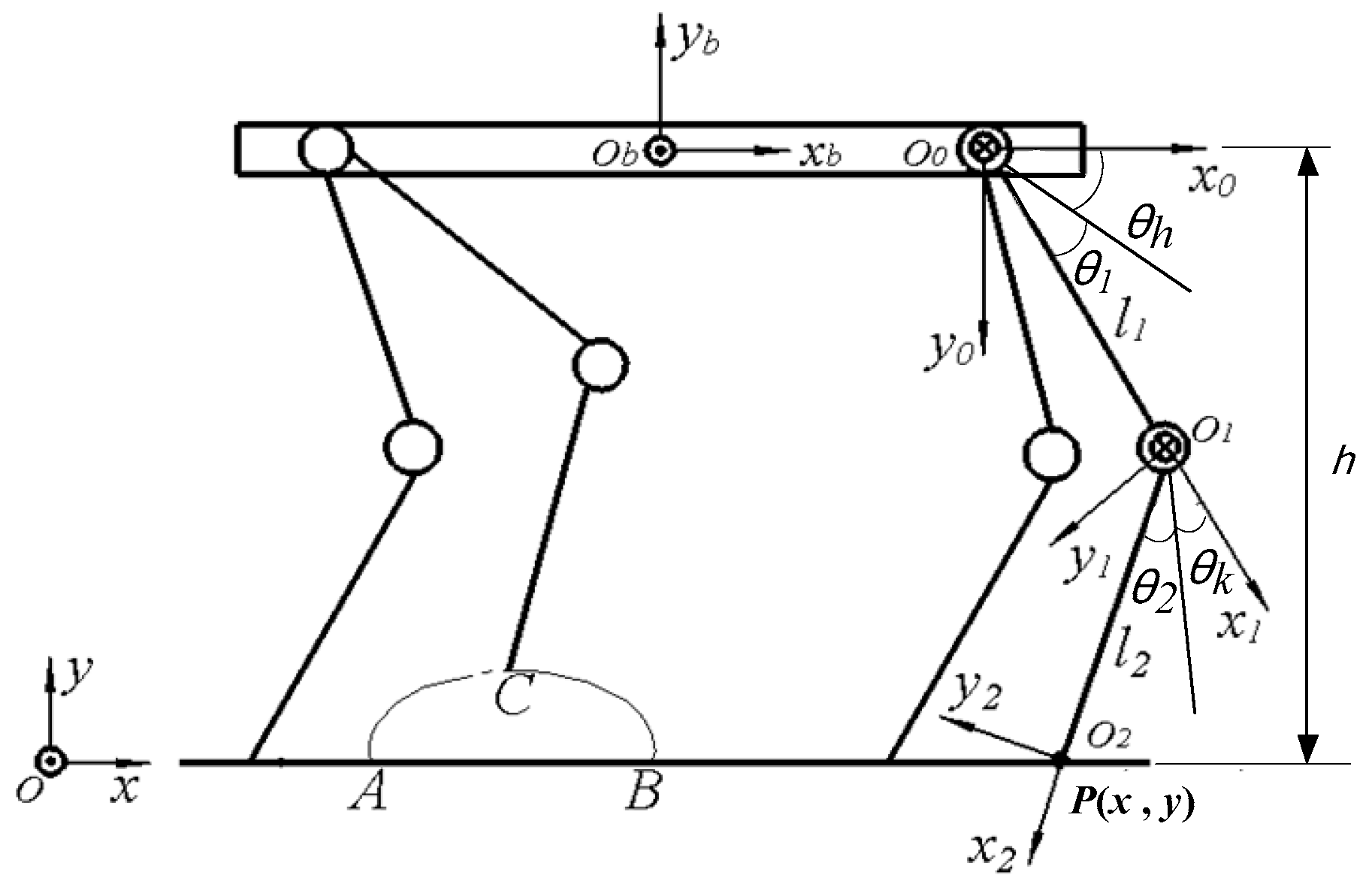
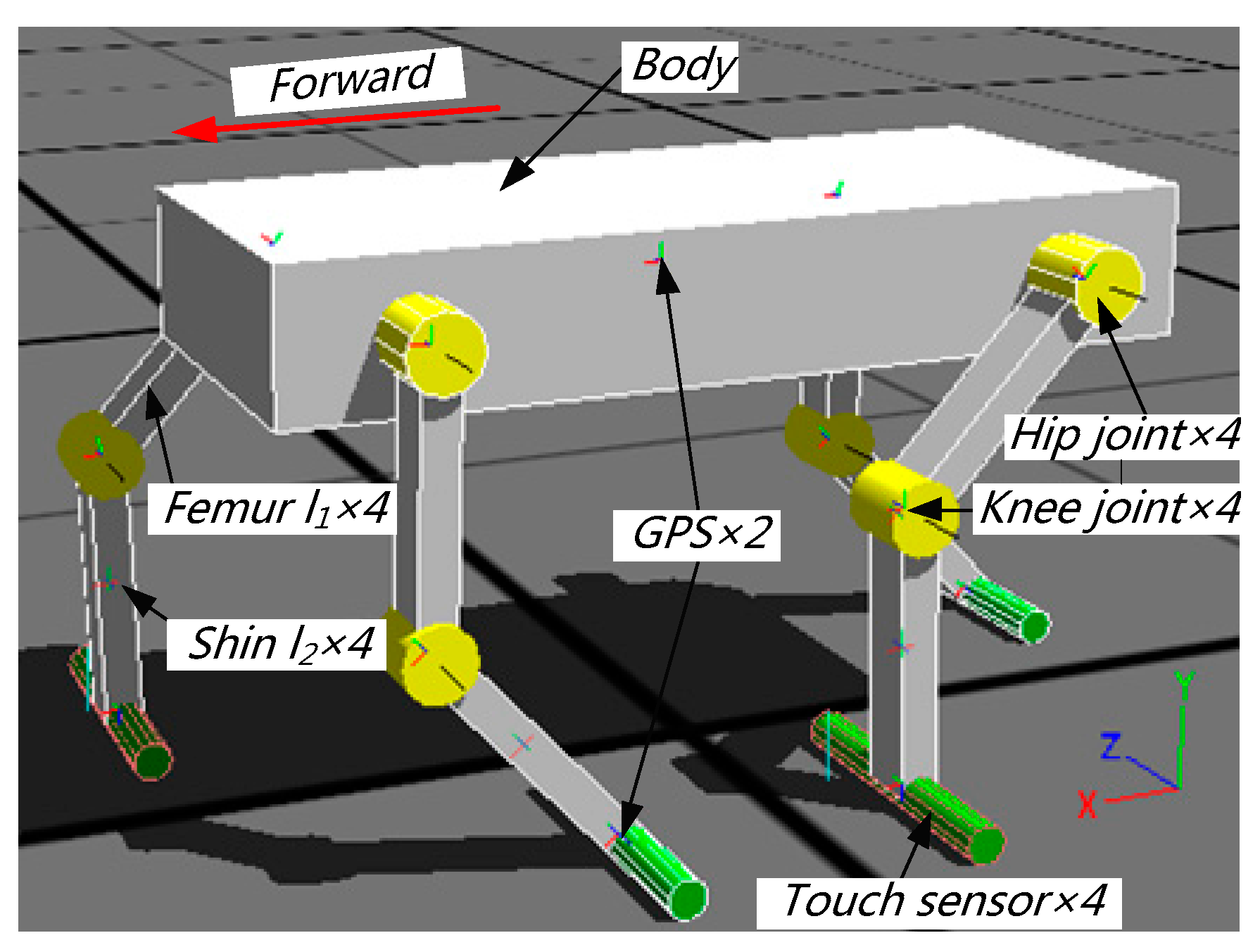
2.1. Modeling and Kinematics Analysis of a Quadruped Robot
A simplified quadruped robot plane model is shown in Figure 1, which consists of nine links: a body, four femurs and four shins. To simplify the analysis and control, the joints configuration of the robot is all-knee.
Figure 1.
Schematic and parameters of the quadruped robot model.
The coordinate system and are the world coordinate system and the local coordinate system fixed in the geometric center of the robot’s body respectively. The orientations are shown in Figure 1, where points to the forward direction of the robot, is perpendicular to the robot’s body and pointing to its back from its abdomen, and is determined by the right hand rule of the coordinate system. To make the modeling more general, a leg is chosen arbitrarily to establish the single leg D-H coordinate system, where the right front leg is selected and the coordinate system is located at its hip joint, as shown in Figure 1. The point is the position description of the robot foot in the coordinate system . According to the D-H notation, the D-H parameters can be described as shown in Table 1.
Table 1.
The D-H notation parameters.
Where and are the balance position angles of hip and knee joints, respectively; and are the rotation angles of the hip and knee joints with respect to their balance position, respectively; and are the lengths of the femur and shin, respectively. By the D-H notation, the angles and corresponding to point can be solved via the inverse kinematics, which is given by
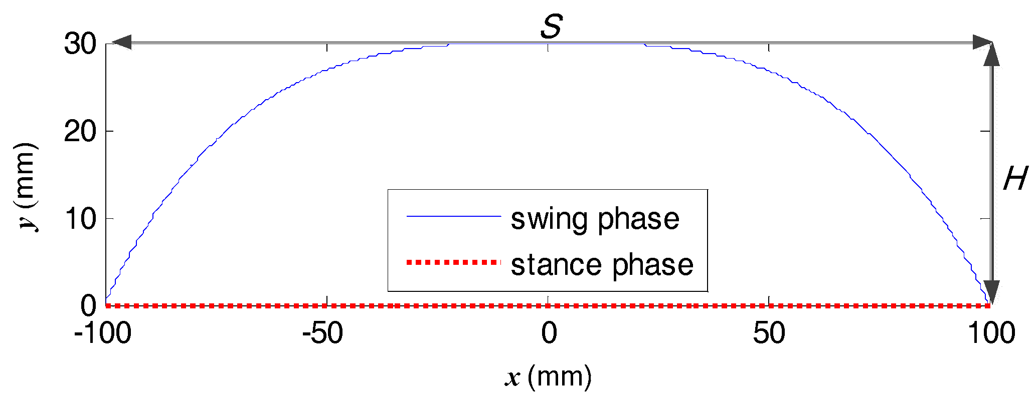
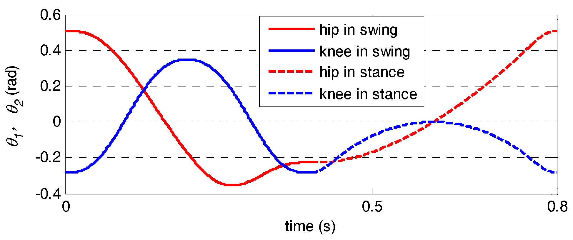
2.2. Foot WT Planning
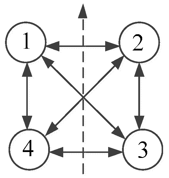
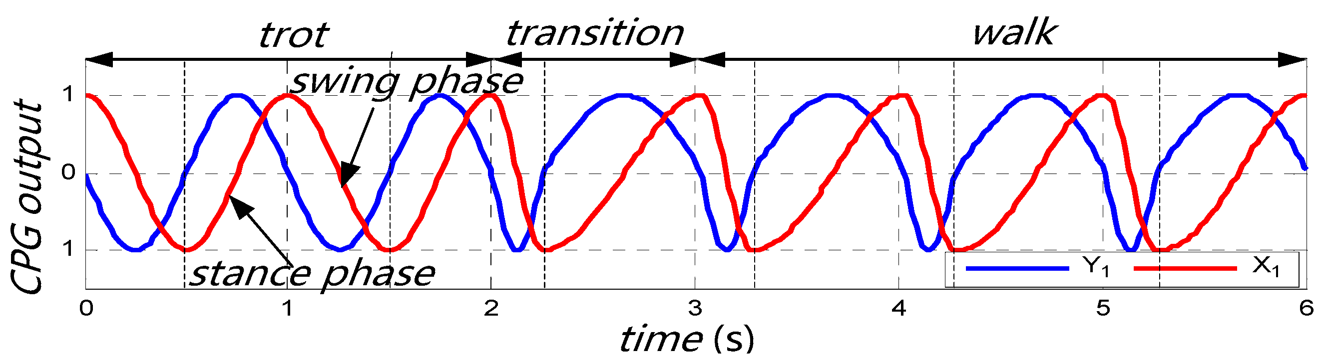
Foot WT mainly involves swing phase and stance phase. As shown in Figure 1, the arc is the swing phase trajectory and is the stance phase trajectory. In [10], a trajectory planning method based on compound cycloid is used to design the swing phase trajectory with the advantage of smooth motion and small mechanical shock. In addition, the method is modified and applied to a quadruped robot foot WT planning in [11]. The modified trajectory is defined as
where is the stride length, is the maximum height of leg raise, and is the swing phase period. By analyzing the first and second derivatives of the equations, we can know that the velocities and accelerations on and of the foot are 0 at the time t = 0 and t = , which reduces the mechanical shock, energy loss and makes the robot’s movement more smooth.
Generally, constant motion is used to plan the stance phase trajectory [11,24]. However, huge acceleration jumps will occur at the start and end moment of the stance phase while using the constant motion to plan it directly, which is harmful to the robot and its locomotion. While taking the example of the planning method of swing phase trajectory to plan the stance phase trajectory, the robot will continue to accelerate and decelerate in its stance phase, which affects the stability and locomotion performance of the robot terribly. In this paper, a compromise approach using the constant motion guiding with a short period of sinusoidal velocity at its start and end moment is adopted to plan the stance phase trajectory. Thus, the smooth transition from zero to constant velocity and constant velocity to zero is realized, which greatly reduce the acceleration jumps and speed fluctuations.
Assuming is the period that the velocity starts from 0 to constant velocity , which is given by
where k is the scaling factor of the transition period and the support phase period . The velocity is determined by
Then the improved stance phase trajectory is described as
where is the height from the foot to the corresponding hip joint. We set the maximum height of leg raise mm, the stride length mm, the swing and stance phase period s. The single-leg single-period foot WT in the plane of coordinate system is shown in Figure 2 (for a unified form, the trajectory is shifted to the origin of the coordinate system ).
Figure 2.
The single-leg single-period foot workspace trajectory (WT).
We set the scaling factor k = 0.1, the hip and knee joints’ balance position , and the parameters used in Equation (1) are chosen as mm. In the hip joint coordinate system , with the foot WT planned above, the coordinated angular displacement curves of the hip joint () and knee joint () in single gait period are shown in Figure 3. Besides, from Figure 3 we see that curves in joint space (motor commands) are smooth and fluent too.
Figure 3.
The angular displacement curves of the hip and knee joints.
3. Improved CPG
In this section, a modified CPG oscillator unit model is first presented for CPG parametric control of a quadruped robot. After that, an improved CPG control model is proposed with smoother gait planning.
3.1. Modified CPG Oscillator Unit Model
In order to realize the CPG parametric control of a quadruped robot, Righetti and Ijspeert [25] presented a modified Hopf oscillator and its phase and frequency can be independently controlled. Their modified Hopf oscillator is applied to control the locomotion of a quadruped robot [26], which is given by
where ; is the amplitude of oscillator; is the frequency of oscillator; and are the frequencies of the stance and swing phases, respectively; is a large positive constant which determines the conversion speed of between and ; and and are positive constants which control the convergence speed of the limit cycle. The greater the value of them, the faster the limit cycle converges. and are the two state variables of the oscillator. The oscillator parameters and dynamic characteristics are analyzed in detail in lots of studies [25,26,27,28,29], It should be noted that, whatever the initial value is, except for the singular point, the Hopf limit cycle is stable.
In order to adjust the quadruped robot’s gait period and duty factor (the ratio of the stance phase period to the gait period) directly and independently to produce the desired rhythm gaits, Equation (7) is modified to
where is the duty factor (in this paper, the rise part of the oscillator output is used as the stance phase), and is the gait period.
3.2. Improved CPG Control Model
The CPG mechanism of creatures contains the coupling relationship of the time domain and the spatial domain at the same time. Similarly, the CPG control network is a distributed network system composed of multiple oscillator units through a certain topological relationship, which simulate the biological CPG mechanism commendably and is very suitable for multi-legged robot distributed control [10,11]. Aiming at the control of a quadruped robot, four CPG oscillator units based on the modified Hopf oscillators are used to form a fully symmetric CPG control network, as shown in Figure 4.
Figure 4.
Full symmetric central pattern generator (CPG) control network of a quadruped robot.
In Figure 4, the numbers 1, 2, 3 and 4 are the left front (LF), right front (RF), right hind (RH), and left hind (LH) legs of a quadruped robot, respectively. The dashed arrow points to the head while the solid arrows represent a certain coupling relationship among the CPG oscillator units. Considering the CPG-NN-WT-based control strategy (which will be introduced in detail in Section 4) presented in this paper, the CPG only needs to output 4 smooth control signals with a certain phase coupling relationship instead of controlling any joint, and its duty factor and gait period are adjustable. To realize the smooth gait planning of quadruped, the CPG based on Hopf oscillators presented in [29] is improved as follows:
- (1)
- In order to adjust the gait period and duty factor directly and independently, the frequency of the Hopf oscillator is modified as Equation (8).
- (2)
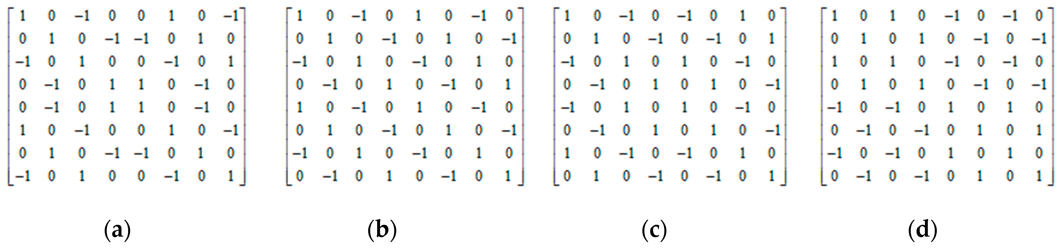
- Parameter is introduced as coupling intensity coefficient among the CPG oscillator units to control the gait transition speed and waveform.
- (3)
- Multiple feedbacks with their corresponding reflex coefficients are simultaneously introduced into the two states (x and y) of the CPG oscillator unit. With the reflex information matrix and reflex coefficient vector, a clear way of expression and implementation is provided to realize the biological reflex modeling.
Then the improved CPG is described as follows:
where and are the outputs of oscillator , and is chosen as the main output of the CPG. The second and third terms on the right side of Equation (9) are the coupling term and feedback term, respectively; is the coupling intensity coefficient among the CPG oscillator units; is the reflex coefficient of the k-th feedback; and are the k-th feedback input of and of oscillator , respectively; is the total number of feedback items; is the relative phase between the oscillator and oscillator ; and is the rotation matrix that describes the phase coupling relationship among the CPG oscillator units. Other parameters are the same as described in Equations (6)–(8). Matrix is given by
where , and is the phase of the oscillator .
Equation (9) can be rewritten as
where , and is the connection weight matrix of the CPG control network, which determines the output of the CPG control network, such as the different gaits and their mutual transition, and are the reflex information matrix and reflex coefficient vector respectively. The walk, trot, pace and gallop are the four typical gaits of quadruped robots and their phase relationships is shown in Table 2 respectively.
Table 2.
Four typical gaits and their matrixes.
After introducing the gait matrix into Equation (11), we can obtain the corresponding connection weight matrix R. Further, the connection weight matrices of the four typical gaits are given by Figure 5.
Figure 5.
Connection weight matrixes of the four typical gaits. (a) walk; (b) trot; (c) pace; (d) gallop.
An important feature of CPG control network is the output waveform of gaits and their mutual transitions. The CPG oscillation units can be coupled with any relative phase, since they are coupled to each other with its two output states by the rotation matrix. Besides, a gait can be transformed to another gait by replacing the corresponding target R directly, and the gait transition point can be selected arbitrarily when expecting the gait transition.
As the walk and trot gaits are the most representative, with the coupling intensity coefficient and respectively, the output waveform of CPG in the walk and trot gaits and their mutual transitions are shown in Figure 6, where , , s, the third term on the right side of Equation (9) is 0 since there is no feedback to the CPG, and in the walk gait while in the trot gait.
Figure 6.
The output waveform of CPG in trot and walk gaits and their mutual conversions. (a) δ = 1, the output waveforms of CPG in tort and walk gait and their mutual transitions; (b) δ = 0.3, the output waveforms of CPG in tort and walk gait and their mutual transitions. The robot’s leg lift sequence is 1-3-2-4 in walk gait.
As can be seen from Figure 6, the gait transition speed and its output waveform are adjusted by independently. Specifically, when is relatively large (as shown in the upper part (a) of Figure 6, ), a gait can be transformed to another gait quickly (the transition time ≤ T). However, due to the relatively strong coupling, the output waveforms rise slowly in the front part of the ascending phase while rising violently in the rear part in walk gait with the duty factor , and the greater the duty factor exceeds 0.5, the more obvious the over-coupling phenomenon is. However, when a smaller coupling intensity coefficient is used, the gait transition speed is reduced relatively, but it can effectively avoid the over-coupling phenomenon and the whole transition process is smoother (as shown in the lower part (b) of Figure 6, ). Therefore, can be used to control the gait transition speed in different situations.
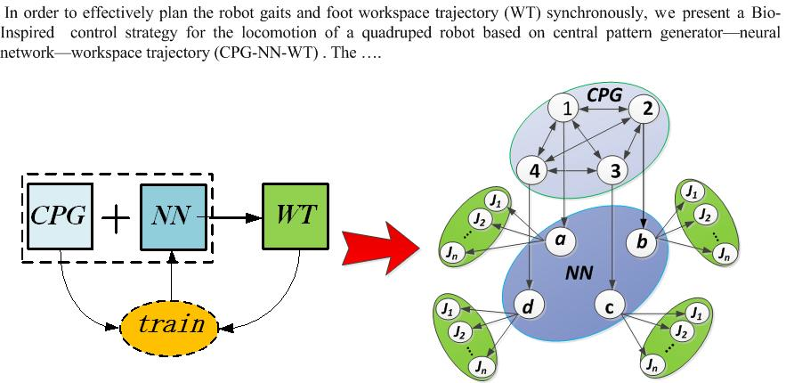
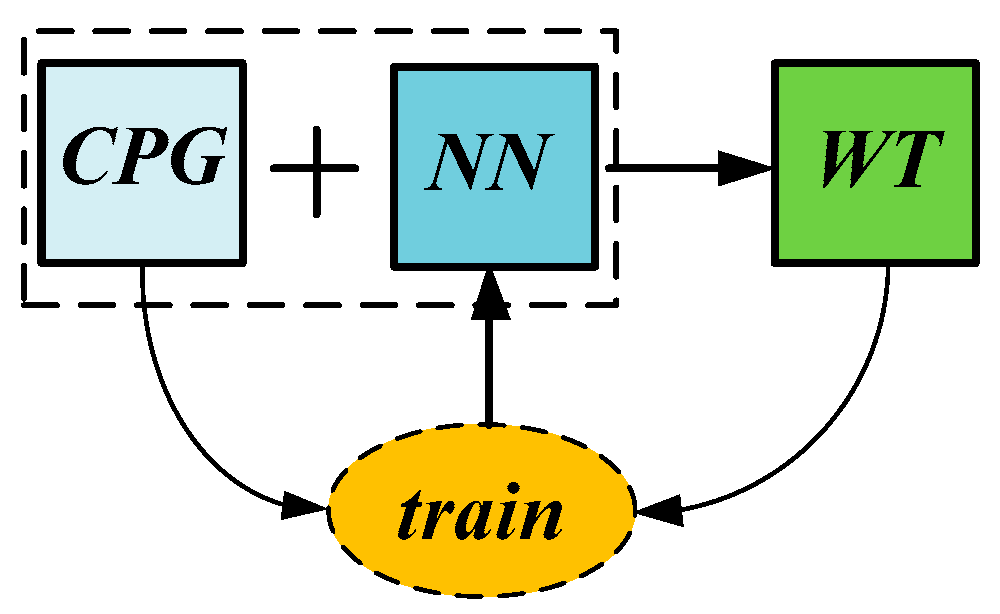
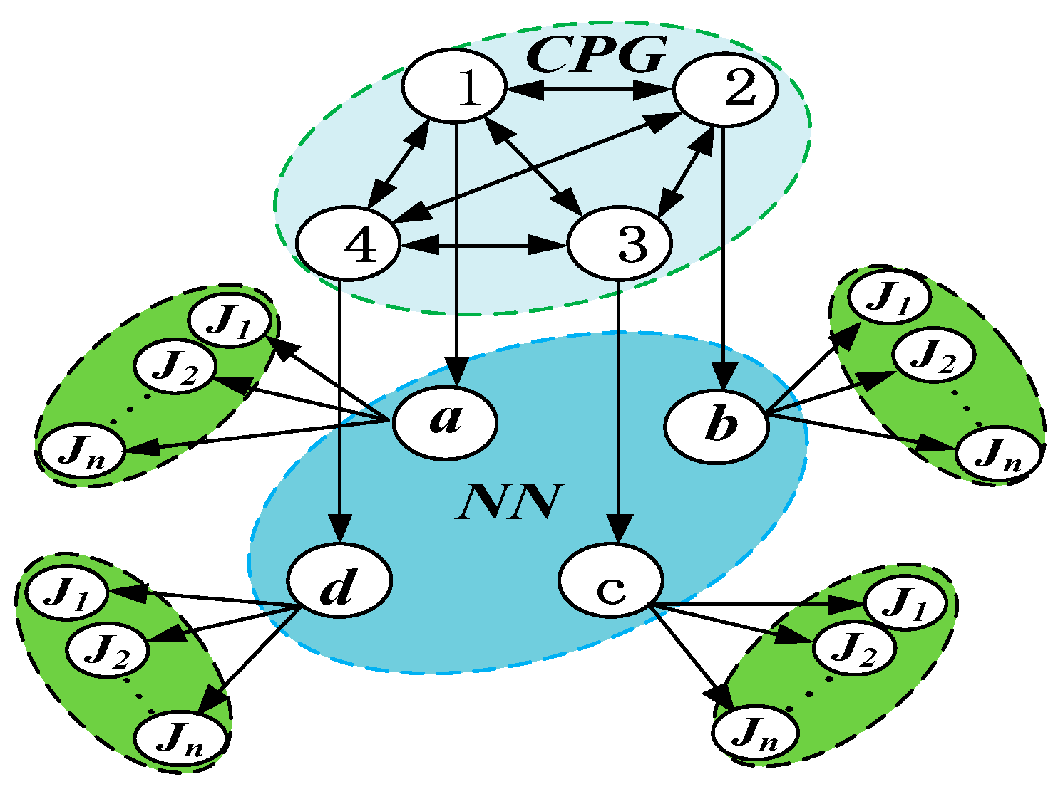
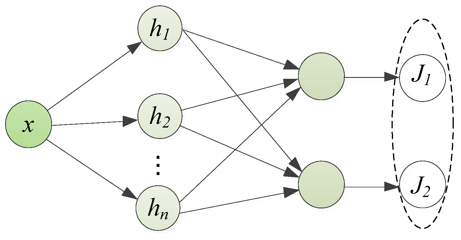
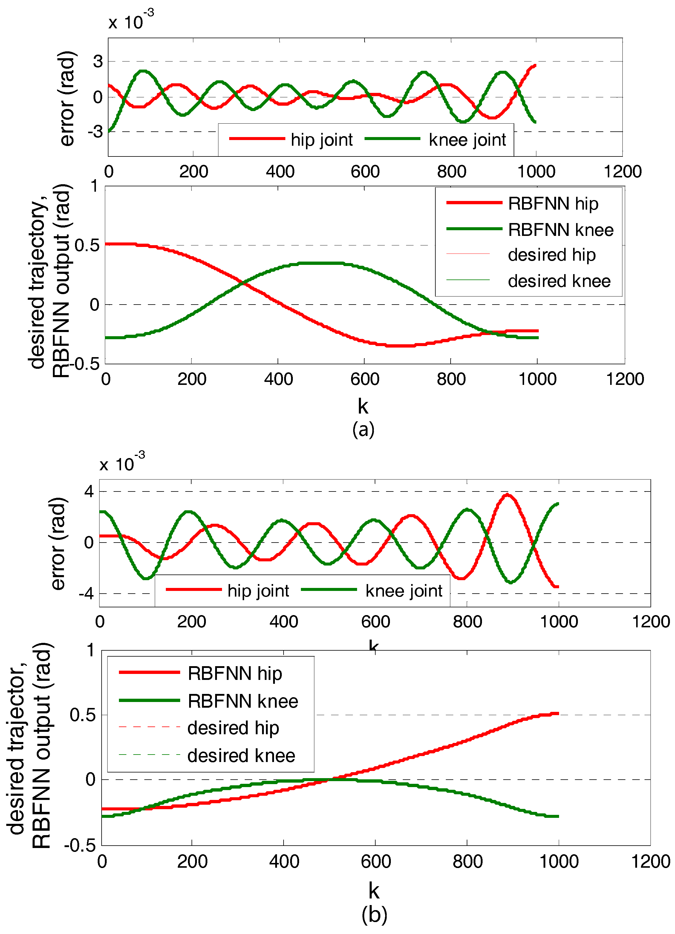
4. CPG-NN-WT-Based Control Strategy
In this section, the CPG-NN-WT model is first presented for the control of a quadruped robot, which take advantage of both CPG-based method and WT-based method. Then the implementation of the proposed CPG-NN-WT-based control strategy is described in detail.
4.1. CPG-NN-WT Control Model
The fundamental idea of the CPG-NN-WT-based control strategy is to combine the advantages of CPG-based method and WT-based method by a plastic intermediate layer, the NN, which converts the CPG output to the preplanned WT. The relationship among them can be depicted as Figure 7.
Figure 7.
Central pattern generator—neural network—workspace trajectory (CPG-NN-WT) relationship diagram.
As shown in Figure 7, the NN can be obtained by training sample pairs, which are the CPG output and the preplanned WT. Consequently, the preplanned WT can be reappeared when using the CPG-NN-WT control model.
In this paper, the CPG-NN-WT control model for a quadruped robot is shown in Figure 8.
Figure 8.
The CPG-NN-WT control model for a quadruped robot.
In Figure 8, the uppermost elliptical dashed box is the CPG layer and the middle elliptical dashed box is the trained NN layer, where a, b, c and d are the four identical NNs, which convert the CPG output into the multi-joint coordinated control signals within a leg (as shown in Figure 8, for example, the NN converts the CPG unit 1 control signal into the coordinated control signals of joint J1, J2, ... Jn of the left front leg), since the NN has the capability of multi-input and multi-output. What is important is that the more joints in a leg that need to be coordinated controlled, the more obvious the advantages of this control model. In Figure 8, we set the subscript n = 2, since the quadruped robot model used in this paper has only hip joint and knee joint within a leg.
4.2. Realization of CPG-NN-WT Control Model
With the preplanned WT and CPG introduced above, the CPG-NN-WT-based control strategy can be achieved after the following steps.
Step 1: the NN choosing and its input and output determining
In this paper, the radial basis function neural network (RBFNN) is chosen for two reasons: (1) It is a local approximation network, which learns fast and can effectively avoid falling into the local minimal. (2) It is a three-layer feed-forward network with a single hidden layer and can approximate any continuous function with arbitrary precision [7,30,31,32,33,34].
Considering the performance and the structure size of the NN as well as computational cost, the NN is defined as the follows: one input to receive the CPG output and outputting two coordinated signals to simultaneously control the hip and knee joints within a leg. However, it can be seen easily form Figure 9 that the CPG output falls in the same range of (−1,1) during both its swing and stance phases. That is, the input of NN is overlapped. Although the NN has the capability to automatically classify if the leg should be in swing or stance phase based on the CPG outputs, it makes the structure size bigger, relatively. Fortunately, each CPG oscillator unit has two outputs, no matter what state it is in, there is a strict correspondence between its two outputs, as shown in Figure 9 (where i = 1).
Figure 9.
The output of single CPG oscillation unit.
The corresponding relationship is: when the CPG oscillator unit output is in the swing phase (in this paper, the decline part of the curve is the swing phase), the other output ; while is in stance phase, the other output .
In order to solve the problem of NN input overlap and make the structure of NN smaller (the smaller the structure of NN, the smaller the computational cost), the corresponding relationship between the two outputs of the CPG oscillator unit is used with the piecewise function method. Two NNs corresponding to the swing and stance phases of a CPG oscillator unit respectively are used to receive the CPG output. Then, the NN is given by
where is the RBFNN; and and are the subsections of the RBFNN corresponding to the swing and stance phases, respectively.
Step 2: NN construction and training
The key point of the RBFNN construction is the nodes in its hidden layer, which is related to the network performance and its computation complexity. In this paper, the hip and knee joints’ coordinated control signals are used as the output, and the main output of the CPG unit with the duty factor β = 0.5 in a gait period is used as the input to train the RBFNN. The total number of the training sample pairs is 2002 (the swing and stance phase are evenly distributed in 1001 pairs respectively). The distribution density of the radial basis function (RBF) is 0.34 for the swing phase neural network and 0.8 for the stance phase neural network . The MATLAB neural network toolbox is used to analyze its number of nodes in hidden layer and other parameters of the RBFNN with its training performance, as shown in Figure 10.
Figure 10.
The training performance of the radial basis function neural network (RBFNN). (a) the performance of training; (b) the performance of training.
In view of the locomotion control of a quadruped robot, the goal of RBFNN training mean square error is chosen to be . It can be seen from Figure 10 that the goal is achieved when the number of the hidden layer nodes of the and reach 9 and 10, respectively. The network structure is shown in Figure 11.
Figure 11.
RBFNN network structure.
In this study, 2000 pairs of test samples (the swing phase and stance phase are evenly distributed in 1000 pairs respectively) are used to test the trained RBFNN. The test results are shown in Figure 12.
Figure 12.
Test performance of the RBFNN. (a) Test performance of ; (b) Test performance of .
It can be seen from Figure 12 that the hip joint and knee joint angular displacement curves of the RBFNN are quite coincident with the curves of the preplanned WT, and their maximum absolute error is under in swing phase and under in stance phase respectively.
Step 3: The Output of CPG-NN-WT Control Model
In simple terms, for the output of CPG-NN-WT control model, its essence is the output of CPG + NN. As walk and trot gaits are the most typical gaits of the quadruped robot, Figure 13 shows the CPG-NN-WT output curves of the walk and trot gaits and their mutual transitions, where , the walk and trot gaits duty factor are , respectively. Other parameters are same as described in Figure 6.
Figure 13.
The CPG-NN-WT outputs.
In Figure 13, the first row of curves is the CPG output, the 2–5 rows are the CPG + NN outputs, namely the CPG-NN-WT outputs, which simultaneously controls the hip and knee joints within a leg to adjust the foot positions on the preplanned WT. As shown in Figure 13, no matter what gaits, or the processes of gait transition the robot is in (Figure 13 shows the most typical walk and trot gaits and their mutual transitions), the CPG-NN-WT output curves are in accordance with the preplanned foot WT which is shown in Figure 3 (Figure 12 analyzes its error), and the curves are continuous, smooth and without any sharp point.
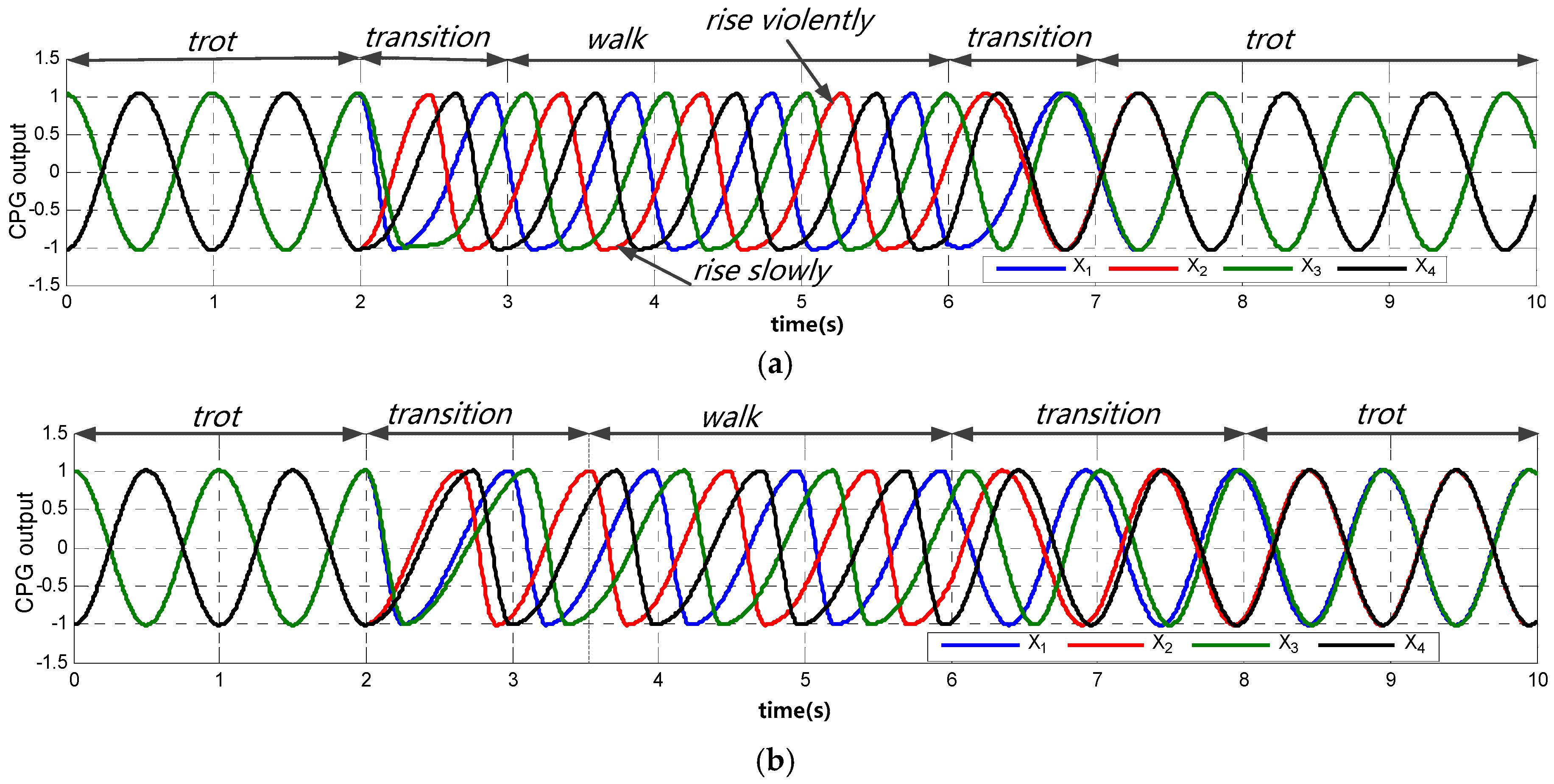
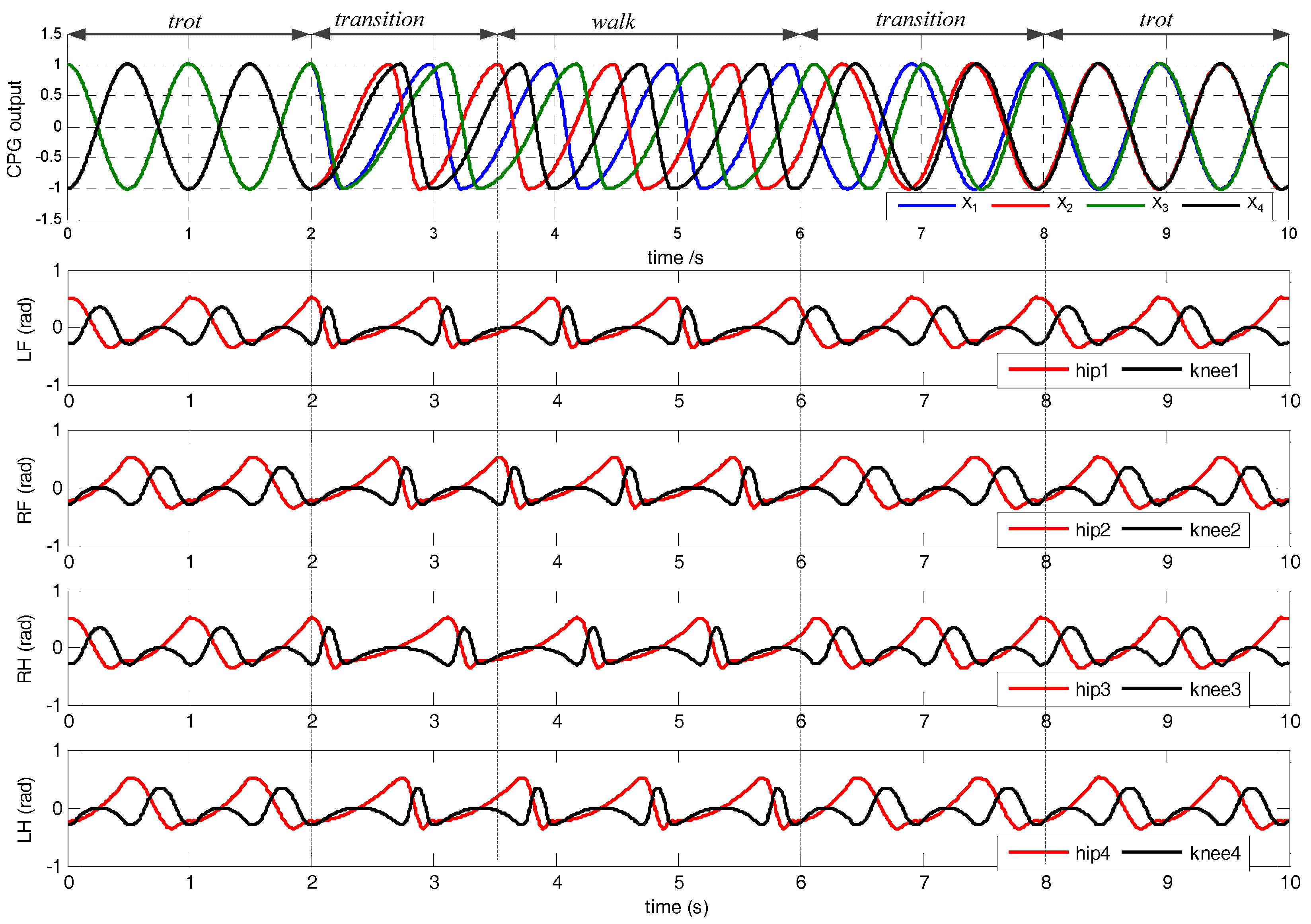
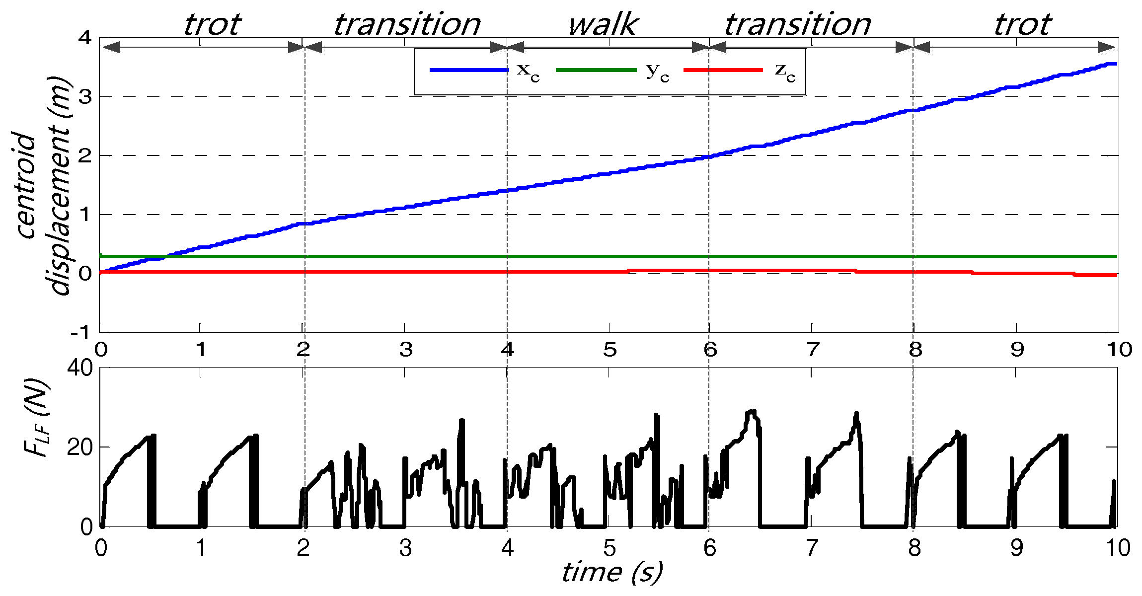
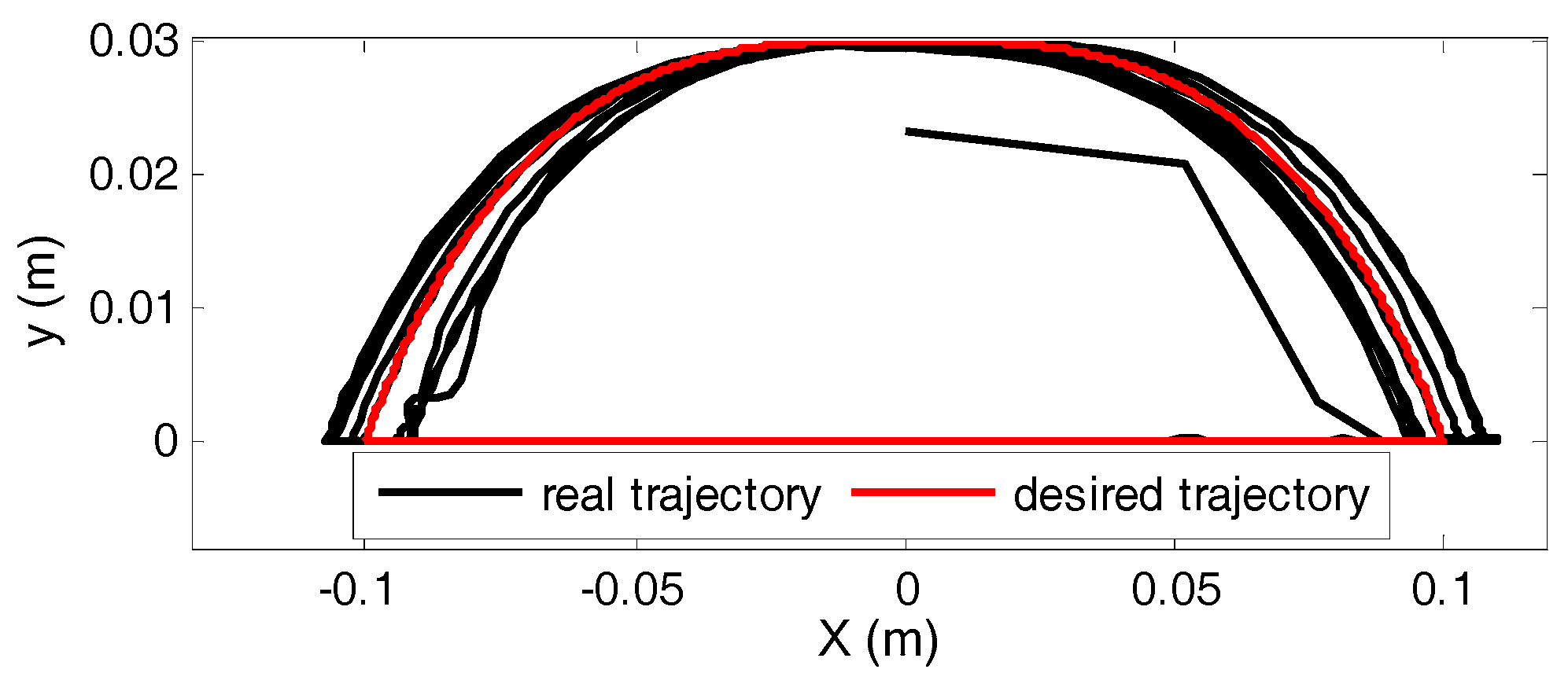
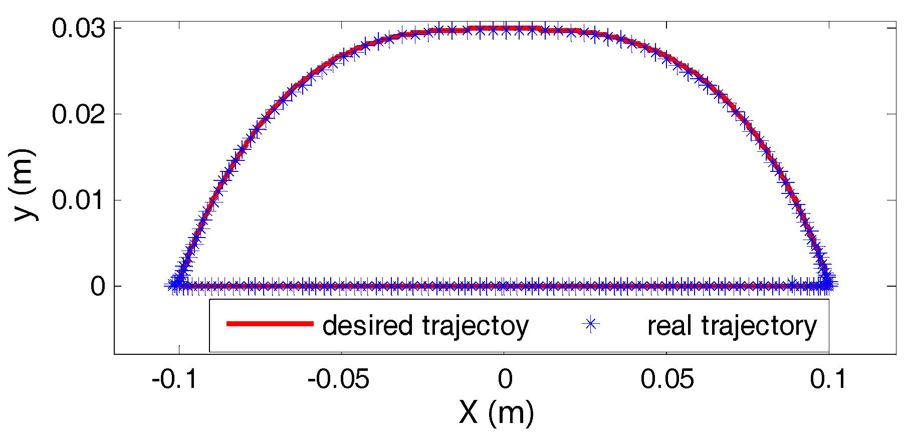
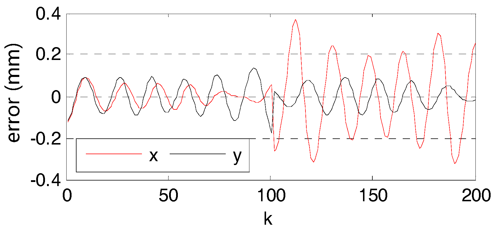
5. Results and Discussion
In order to validate the correctness and validity of the presented CPG-NN-WT-based control strategy, the virtual prototype simulation based on Webots and the experiments with a real quadruped robot are carried out, respectively.
5.1. Virtual Prototype Simulation
Webots is a development environment used to model, program and simulate mobile robots. First of all, a quadruple robot virtual prototype is created in the Webots simulation platform, as shown in Figure 14, where its components and configurations are the same as described in Figure 1. In addition, in order to facilitate the observation of locomotion performance and foot trajectory of the robot, the CPS sensors (used to obtain the location of GPS points in the world coordinate system of the simulation platform) are added in its body geometric center and foot point respectively. Meanwhile, the touch sensors were added at its foot, which were used to measure the force of the foot in the vertical direction.
Figure 14.
The quadruped robot virtual prototype.
The basic parameters of the robot virtual prototype are shown in Table 3.
Table 3.
The robot virtual prototype parameters.
The simulation results with the representative trot and walk gaits and their mutual transitions are shown in Figure 15, Figure 16, Figure 17 and Figure 18, where the parameters of the CPG-NN-WT control model are the same as in Figure 13.
Figure 15.
Centroid displacement and the foot force bearing status of the robot virtual prototype.
Figure 16.
Foot trajectories.
Figure 17.
The foot trajectories during the first gait period.
Figure 18.
Absolute error of the foot trajectory during the first gait period.
The upper part of Figure 15 is the robot centroid displacement (geometric center of the robot body), and the lower part is the foot force bearing status of the left front leg. As shown in the upper part of Figure 15, during the trot, walk gaits and their mutual transition process, the centroid displacement curves in the forward direction is smooth and coherent without large fluctuations. In its vertical direction , the curve is smooth and has almost no fluctuation. Further, the slope of the forward direction curve of centroid displacement is large in the trot gait but small in the walk gait due to the different duty factors of the two gaits. In addition, since the yaw control is not taken into account, the lateral displacement curve of centroid is shifted during gait transition. As shown in the lower part of Figure 15, during the trot, walk gaits or their mutual transition process, the force of the foot is balanced and has small mechanical impact without sharp mutation relatively. (In order to more intuitively reflect the stress state, there is no filtering processing).
Figure 16 shows the comparison of the preplanned WT (desired trajectory) with real trajectory of the left front leg when robot is traveling. As shown in Figure 16, there are left or right shifts between the real trajectory curves and the preplanned WT curve due to the yaw angle, which is generated during the gait transition but which is not taken into account while processing data. However, the real trajectories are still in accordance with the preplanned WT if the effect of yaw angle is not taken into account, e.g., the real trajectory of which the yaw angle is 0 during the first gait period is in accordance with the preplanned WT well, and its maximum absolute error in x is under 0.4 mm, which is about S and its maximum absolute error in y is under 0.2 mm, which is about H, as shown in Figure 17 and Figure 18.
Figure 19 shows the simulation video captures of the virtual prototype in the Webots platform. Throughout the whole simulation process, the locomotion of the quadruped robot is smooth and fluent. Referring to Figure 13, it can be seen that during the whole simulation process, the “CPG part” has played its advantages in gait planning and controlling well, while the “NN part” has the ability to adjust the foot positions according to the preplanned WT. It is verified that the CPG-NN-WT-based control strategy presented in this paper can effectively integrate the advantages of CPG-based method with WT-based method in the locomotion control of a quadruped robot.
Figure 19.
The simulation video capture, where (a) the typical trot gait; (b) starting the transition from trot to walk gait; (c) the gait transition process; (d) transition finished; (e), (f), (g) and (h) the typical walk gait, robot’s leg lift sequence is 1-3-2-4; (i) starting the transition from walk to trot gait; (j) and (k) the gait transition process; (l) transition finished; (m) the typical trot gait.
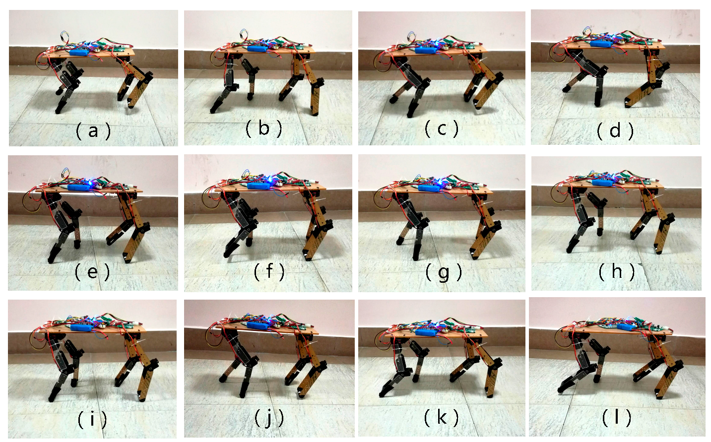
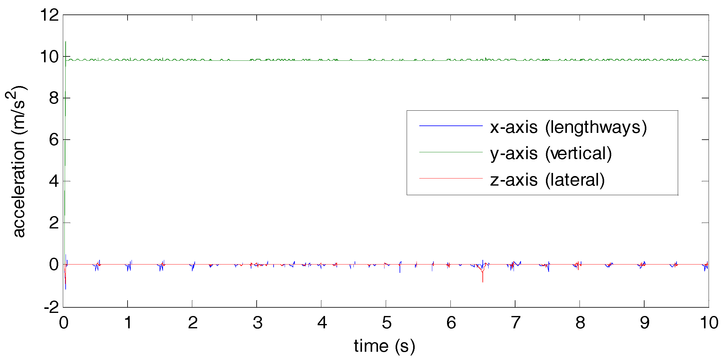
5.2. Experiment with a Real Quadruped Robot
After the virtual prototype simulation, the CPG-NN-WT control model with the same parameters is applied to a physical prototype whose basic parameters are shown in Table 4. Besides, an accelerometer is added in its body geometric center to measure the accelerations in three directions, the x-axis (lengthways), the y-axis (vertical) and the z-axis (lateral).
Table 4.
Physical prototype parameters.
In order to validate the presented control strategy, the experiment results of the trot, walk gaits and their mutual conversions are shown in Figure 20. The robot’s actual stride length S is about 0.2 m, the gait period T is about 1 s, and the maximum height of leg raise H is about 0.03 m, which is basically consistent with the parameters set in CPG-NN-WT and preplanned foot WT. Besides, the average move speed in 10 seconds is about 0.4 m/s and the biggest lateral shifting is 0.1 m, which is about 0.5 S.
Figure 20.
Photos of real robot experiment. where (a) the typical trot gait; (b) starting the transition from trot to walk gait; (c): the gait transition process; (d) transition finished; (e), (f), (g) and (h) the typical walk gait; (i) starting the transition from walk to trot gait; (j) the gait transition process; (k) transition finished; (l) the typical trot gait.
The acceleration curves of the robot when moving are shown in Figure 21. In the vertical direction (y-axis), the acceleration is stable at around 9.8 m/s2 (gravitational acceleration), which shows the predesigned WT reduce the mechanical shock well. In the lengthways direction (x-axis), the fluctuation of the acceleration is bigger in trot but smaller in walk due to the walk gait being more stable than trot. In the lateral direction (z-axis), except for the gaits transition period, the acceleration range is very small.
Figure 21.
Acceleration curves of the robot.
To sum up, from the view of the whole moving process, the locomotion of the physical prototype is fluent and the body shakes are in an acceptable range. In addition, from the hip joint coordinate system, the foot trajectory is still in accordance with the preplanned WT well, which verifies that the presented control strategy is correct and effective.
6. Conclusions
Some concluding remarks would be summarized as follows.
- (1)
- An improved foot WT based on the compound cycloid is planned with advantages of low mechanical impact, smooth movement and sleek trajectory.
- (2)
- An improved CPG based on Hopf oscillators put forward in this paper can effectively realize the smooth gait planning by adjusting its internal parameters.
- (3)
- A biologically inspired control strategy based on CPG-NN-WT is presented for locomotion control of a quadruped robot, which can effectively integrate the advantages of CPG-based method with WT-based method. Besides, the presented control strategy provides an effective way to realize the multi-joint coordination control within a leg, since the NN has the capability of multi-input and multi-output. Furthermore, theoretically, the CPG-NN-WT control model can output any desired periodic WT, which depends only on the complexity of the NN.
By bringing in feedbacks and referring to the neural system of legged animals, the adaptive dynamic walking on irregular terrains using reflexes and online learning of neural networks is being studied.
Acknowledgments
We would like to thank the support from the National Natural Science Foundation of China(No. 51575456), the Open Research Fund of Key Laboratory of Integration and application of solar energy technology (2017-TYN-Y-02), the Key scientific research fund of Xihua University (Grand No. Z1420210, Z1620211), Sichuan International S & T Cooperation and Exchange R & D Project (No. 2017HH0049), the Open Research Fund of Health Management Development Center (Xihua University, No. s2jj2017-023, s2jj2017-039), and the Innovation Fund of Postgraduate, Xihua University (ycjj2017034).
Author Contributions
Yinquan Zeng and Junmin Li co-organized the work and wrote the manuscript draft; Yinquan Zeng and Erwei Ren co-performed the experiments; Simon X. Yang supervised the research and commented on the manuscript writing.
Conflicts of Interest
The authors declare no conflict of interest.
References
- Ijspeert, A.J. Central pattern generators for locomotion control in animals and robots: A review. Neural Netw. 2008, 21, 642–653. [Google Scholar] [CrossRef] [PubMed]
- Kalakrishnan, M.; Buchli, J.; Pastor, P.; Mistry, M.; Schaal, S. Learning, planning, and control for quadruped locomotion over challenging terrain. Int. J. Robot. Res. 2011, 30, 236–258. [Google Scholar] [CrossRef]
- Kalakrishnan, M.; Buchli, J.; Pastor, P.; Mistry, M.; Schaal, S. Fast, robust quadruped locomotion over challenging terrain. In Proceedings of the 2010 IEEE International Conference on Robotics and Automation, Anchorage, AK, USA, 3–7 May 2010. [Google Scholar]
- Lei, J.; Wang, F.; Yu, H.; Wang, T.; Yuan, P. Energy efficiency analysis of quadruped robot with trot gait and combined cycloid foot trajectory. Chin. J. Mech. Eng. 2014, 27, 138–145. [Google Scholar] [CrossRef]
- Xie, H.; Shang, J.; Ahmadi, M. Adaptive control strategies for quadruped robot on unperceived slopedterrain. Int. J. Robot. Autom. 2015, 30, 90–111. [Google Scholar]
- Li, J.; Wang, J.; Yang, S.X.; Zhou, K.; Tang, H. Gait Planning and Stability Control of a Quadruped Robot. Comput. Intell. Neurosci. 2016, 2016, 9853070. [Google Scholar] [CrossRef] [PubMed]
- Qian, X.; Huang, H.; Chen, X.; Huang, T. Generalized Hybrid Constructive Learning Algorithm for Multioutput RBF Networks. IEEE Trans. Cybern. 2017, 47, 3634–3648. [Google Scholar] [CrossRef] [PubMed]
- Matos, V.; Santos, C.P. Omnidirectional locomotion in a quadruped robot: A CPG-based approach. In Proceedings of the 2010 IEEE/RSJ International Conference on Intelligent Robots and Systems, Taipei, Taiwan, 18–22 October 2010; Volume 6219, pp. 3392–3397. [Google Scholar]
- Koco, E.; Mutka, A.; Kovacic, Z. New parameterized foot trajectory shape for multi-gait quadruped locomotion with state machine-based approach for executing gait transitions. In Proceedings of the 2014 22nd Mediterranean Conference on Control and Automation, Palermo, Italy, 16–19 June 2014; pp. 1533–1539. [Google Scholar]
- Wu, Q.; Liu, C.; Zhang, J.; Chen, Q. Survey of locomotion control of legged robots inspired by biological concept. Sci. China Ser. F Inf. Sci. 2009, 52, 1715–1729. [Google Scholar] [CrossRef]
- Tran, D.T.; Koo, I.M.; Lee, Y.H.; Moon, H.; Park, S.; Koo, J.C.; Choi, H.R. Central pattern generator based reflexive control of quadruped walking robots using a recurrent neural network. Robot. Auton. Syst. 2014, 62, 1497–1516. [Google Scholar] [CrossRef]
- Matsuoka, K. Mechanisms of frequency and pattern control in the neural rhythm generators. Biol. Cybern. 1987, 56, 345–353. [Google Scholar] [CrossRef] [PubMed]
- Kimura, H.; Fukuoka, Y.; Hada, Y.; Takase, K. Adaptive Dynamic Walking of a Quadruped Robot on Irregular Terrain Using a Neural System Model; Springer: Berlin/Heidelberg, Germany, 2003. [Google Scholar]
- Tsujita, K.; Toui, H.; Tsuchiya, K. Dynamic turning control of a quadruped locomotion robot using oscillators. Adv. Robot. 2005, 19, 1115–1133. [Google Scholar] [CrossRef]
- Sun, X. Kuramoto Model; Springer: New York, NY, USA, 2013. [Google Scholar]
- Acebron, J.A.; Bonilla, L.L.; Vicente, C.J.P.; Ritort, F.; Spigler, R. The Kuramoto model: A simple paradigm for synchronization phenomena. Rev. Mod. Phys. 2005, 77, 137–185. [Google Scholar] [CrossRef]
- Zhang, J.; Masayoshi, T.; Chen, Q.; Liu, C. Dynamic Walking of AIBO with Hopf Oscillators. Chin. J. Mech. Eng. 2011, 24, 612–617. [Google Scholar] [CrossRef]
- Hu, Y.; Liang, J.; Wang, T. Parameter Synthesis of Coupled Nonlinear Oscillators for CPG-Based Robotic Locomotion. IEEE Trans. Ind. Electron. 2014, 61, 6183–6191. [Google Scholar] [CrossRef]
- Yu, H.; Gao, H.; Ding, L.; Li, M.; Deng, Z.; Liu, G. Gait Generation With Smooth Transition Using CPG-Based Locomotion Control for Hexapod Walking Robot. IEEE Trans. Ind. Electron. 2016, 63, 5488–5500. [Google Scholar] [CrossRef]
- Kwon, O.; Jeon, K.S.; Park, J.H. Optimal trajectory generation for biped robots walking up-and-down stairs. J. Mech. Sci. Technol. 2006, 20, 612–620. [Google Scholar] [CrossRef]
- Ma, S.; Tomiyama, T.; Wada, H. Omnidirectional static walking of a quadruped robot. IEEE Trans. Robot. 2005, 21, 152–161. [Google Scholar] [CrossRef]
- Liu, C.J.; Wang, D.W.; Chen, Q.J. Locomotion Control Of Quadruped Robots Based on Workspace Trajectory Modulations. Int. J. Robot. Autom. 2012, 27, 345–354. [Google Scholar] [CrossRef]
- Sakakibara, Y.; Kan, K.; Hosoda, Y.; Hattori, M. Foot trajectory for a quadruped walking machine. In Proceedings of the IROS ‘90 IEEE International Workshop on Intelligent Robots and Systems ‘90 ‘towards A New Frontier of Applications’, Ibaraki, Japan, 3–6 July 1990; Volume 1, pp. 315–322. [Google Scholar]
- Wang, L.; Wang, Z.; Wang, S.; He, Y. Strategy of Foot Trajectory Generation for Hydraulic Quadruped Robots Gait Planning. J. Mech. Eng. 2013, 49, 39–44. [Google Scholar] [CrossRef]
- Righetti, L.; Ijspeert, A.J. Design Methodologies for Central Pattern Generators: An Application to Crawling Humanoids. Robotics: Science and Systems II; University of Pennsylvania: Philadelphia, PA, USA, 2006. [Google Scholar]
- Righetti, L.; Ijspeert, A.J. Pattern generators with sensory feedback for the control of quadruped locomotion. In Proceedings of the IEEE International Conference on Robotics and Automation, Pasadena, CA, USA, 19–23 May 2008; pp. 819–824. [Google Scholar]
- Smith, J.A. Galloping in an Underactuated Quadrupedal Robot. Int. J. Robot. Autom. 2015, 30. [Google Scholar] [CrossRef]
- Ren, J.; Xu, H.; Gan, S.; Wang, B. CPG modele design based on hopf oscillator for hexapod robots gait. CAAI Trans. Intell. Syst. 2016, 11, 627–634. [Google Scholar]
- Li, H.; Han, B.; Luo, Q. Inter-limb and intra-limb coordination control of quadruped robots. J. Beijing Inst. Technol. 2015, 4, 478–486. [Google Scholar]
- Lee, N.K.; Wang, D. Realization of Generalized RBF Network. Appl. Spectrosc. 2003, 62, 341–344. [Google Scholar]
- Nabney, I.T. Efficient training of RBF networks for classification. Int. J. Neural Syst. 2004, 14, 201–208. [Google Scholar] [CrossRef] [PubMed]
- He, W.; Chen, Y.; Yin, Z. Adaptive Neural Network Control of an Uncertain Robot With Full-State Constraints. IEEE Trans. Cybern. 2015, 46, 620–629. [Google Scholar] [CrossRef] [PubMed]
- Chen, H.; Yu, G.; Xia, H. Online Modeling With Tunable RBF Network. IEEE Trans. Cybern. 2013, 43, 935–947. [Google Scholar] [CrossRef] [PubMed]
- Fortuna, L.; Arena, P.; Balya, D.; Zarandy, A. Cellular neural networks: A paradigm for nonlinear spatio-temporal processing. IEEE Circuits Syst. Mag. 2001, 1, 6–21. [Google Scholar] [CrossRef]
© 2018 by the authors. Licensee MDPI, Basel, Switzerland. This article is an open access article distributed under the terms and conditions of the Creative Commons Attribution (CC BY) license (http://creativecommons.org/licenses/by/4.0/).