Article

The Stiffness and Damping Characteristics of a Dual-Chamber Air Spring Device Applied to Motion Suppression of Marine Structures

1
Institute of Mechanics, Chinese Academy of Sciences, Beijing 100190, China
2
Collaborative Innovation Center for Advanced Ship and Deep-Sea Exploration, State Key Laboratory of Hydraulic Engineering Simulation and Safety, Tianjin University, Tianjin 300072, China
*
Author to whom correspondence should be addressed.
Appl. Sci. 2016, 6(3), 74; https://doi.org/10.3390/app6030074
Submission received: 10 November 2015 / Revised: 23 February 2016 / Accepted: 26 February 2016 / Published: 8 March 2016
(This article belongs to the Special Issue Acoustic and Elastic Waves: Recent Trends in Science and Engineering)

Abstract

:
Dual-chamber air springs are used as a key component for vibration isolation in some industrial applications. The working principle of the dual-chamber air spring device as applied to motion suppression of marine structures is similar to that of the traditional air spring, but they differ in their specific characteristics. The stiffness and damping of the dual-chamber air spring device determine the extent of motion suppression. In this article, we investigate the stiffness and damping characteristics of a dual-chamber air spring device applied to marine structure motion suppression using orthogonal analysis and an experimental method. We measure the effects of volume ratio, orifice ratio, excitation amplitude, and frequency on the stiffness and damping of the dual-chamber vibration absorber. Based on the experimental results, a higher-order non-linear regression method is obtained. We achieve a rapid calculation model for dual-chamber air spring stiffness and damping, which can provide guidance to project design.

1. Introduction

Marine structure safety, especially in the deep sea, is an important concern. The deep-sea floating platform is one of the most important large structures used in ocean energy exploitation. Dynamic responses due to the wind and wave effects must be considered to ensure a safe design [1]. The combined action of complex multiple loads could cause a large vibration amplitude in marine structures [2,3]. Large amplitude and alternating vibration are the main detrimental effects that reduce the safety and fatigue life of a deep-sea platform. In the field of civil engineering, engineers use a wide variety of energy-absorbing devices to reduce the vibration of building structures. These energy-absorbing devices may also be applied to the problem of vibration suppression of deep-sea marine structures.
The vibration of a floating platform could be reduced using active or passive controls [4,5] and various devices have been proposed. A Tuned Liquid Column Damper (TLCD), a kind of passive vibration control device to suppress movement, was proposed by Sakai [6] in 1989. Lee et al. [7,8] first used the TLCD to suppress the surge and sway motions vibration of a Tension Leg Platform (TLP). Taflanidis et al. [9] further developed a simulation-based method for the design of mass dampers applied for the response mitigation of tension lag platforms. Lee et al. [10] experimentally studied the harmonic responses of the TLCD for wind excitations. Tanmoy et al. [11] studied the effective performance of TLCD and another passive vibration-mitigating device, a tuned liquid column ball damper for the control of wave-induced vibration. Zeng et al. [12] invented a new type of energy-absorbing device, the S-shaped TLCD. The S-shaped TLCD could effectively suppress the horizontal movement and vertical in-plane rotation of a TLP. Although these devices were effective for the suppression of surge and sway motion, TLCD was ineffective at the suppression of vertical movement, and sometime even enhanced this movement [10]. The vertical movement of the floating structures significantly impacts the strength and fatigue of the tension leg and mooring system, and the inability of these devices to suppress this movement could decrease the safety and service life of the structure.
Vibration-induced vertical motion of TLPs could be balanced by using absorbers with air springs. Dual-chamber air springs are an effective energy-absorbing device used as a key component for vibration isolation. Rijken, Bian, and Spillane et al. [13,14,15] applied a system of vibration absorbers using dual-chamber air springs and water columns to suppress resonant motions and studied the effects of the orifice ratio for structural damping. Bachrach and Rivin [16] studied the complex dynamic stiffness of the damper spring, a function of the excitation frequency. The experimental results measured by Kim and Lee [17] for a dual-chamber pneumatic spring exhibited significant amplitude-dependent nonlinear behavior. Jing et al. [18,19,20] proposed a characteristic output spectrum nonlinear (nCOS) method. The nCOS method is based on the theory of Volterra series expansion. They used the nCOS method for analysis and design of an air spring in a nonlinear vehicle suspension system. These studies focused on traditional forms of a dual-chamber air spring.
A dual-chamber air spring device applied to marine structure motion suppression requires a gas-liquid coupling air spring structure. This differs from the traditional air spring both in structure type and in the vibration characteristics. The compression of the gas in the traditional air spring was controlled by a piston, which acted on the pressure surface of the air spring [21,22,23]. As shown in Figure 1a, the displacement of the piston, x0, causes a compression of the air in the upper chamber. The pressure variation of the air spring chamber is of the same phase and amplitude as the external load. For the gas-liquid coupling air spring device applied to motion suppression of marine structures, a liquid column can also move in an independent manner. As shown in Figure 1b, the amount of compressed air in the air chamber is the relative displacement between the liquid column and the top of the air spring, i.e. x1x0. The movement of the liquid column (similar to the piston) and the external excitation can differ in phases and amplitude. The stiffness and damping characteristics of this kind of dual-chamber air spring have not been investigated.
The two main determinants of structure movement suppression effect are the stiffness and damping of the energy-absorbing device. Previous studies of damping and stiffness focused on the traditional air spring, and used an approximation to simulate air flow through the orifice plates [24,25,26]. These results may not apply to the gas-liquid coupling dual-chamber air spring device. Moreover, few factors were investigated and analyzed. There is not a comprehensive study on which factors affect the stiffness and damping characteristics of dual-chamber air spring. Further studies must be carried out on the gas-liquid coupling dual-chamber air spring device.
Here, we investigate the damping and stiffness of a dual-chamber air spring device applied to motion suppression of marine structures. We used orthogonal analysis and an experimental method and found that stiffness and damping are a function of the volume ratio, orifice ratio, excitation amplitude, and frequency. We then measured the effects of these four factors on dual-chamber vibration absorber stiffness and damping. Based on the experimental results, we used higher-order non-linear regression method and generated a rapid calculation model for dual-chamber air spring stiffness and damping, which can provide guidance for future project design.

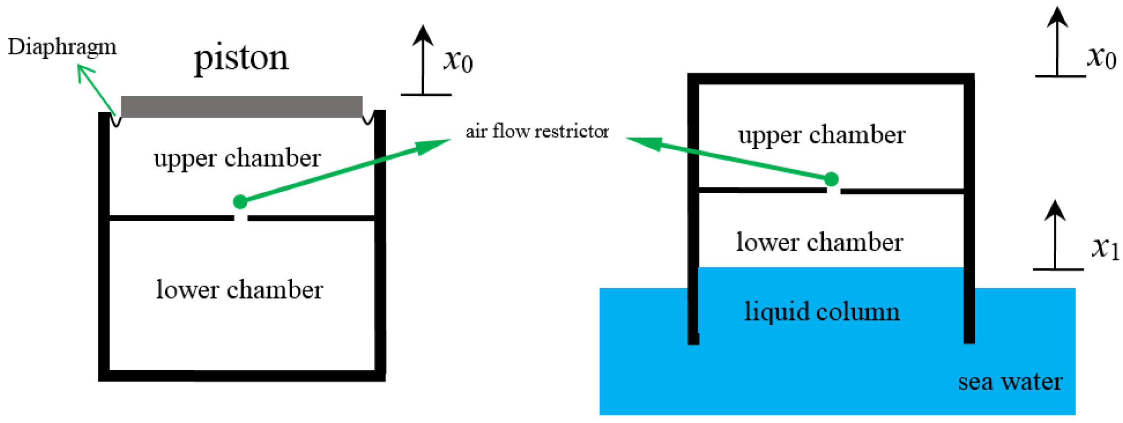
2. Theoretical Analysis
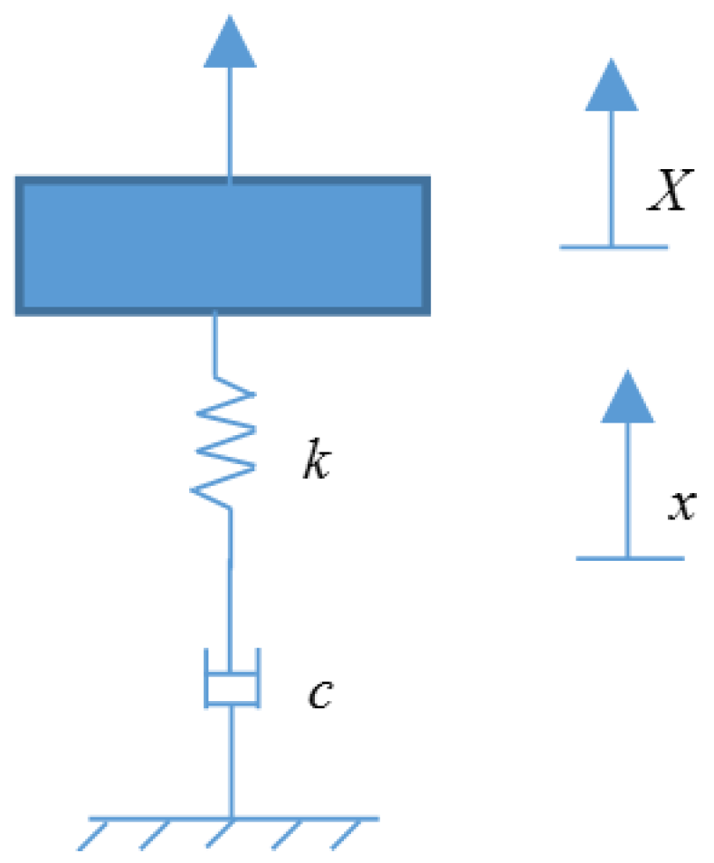
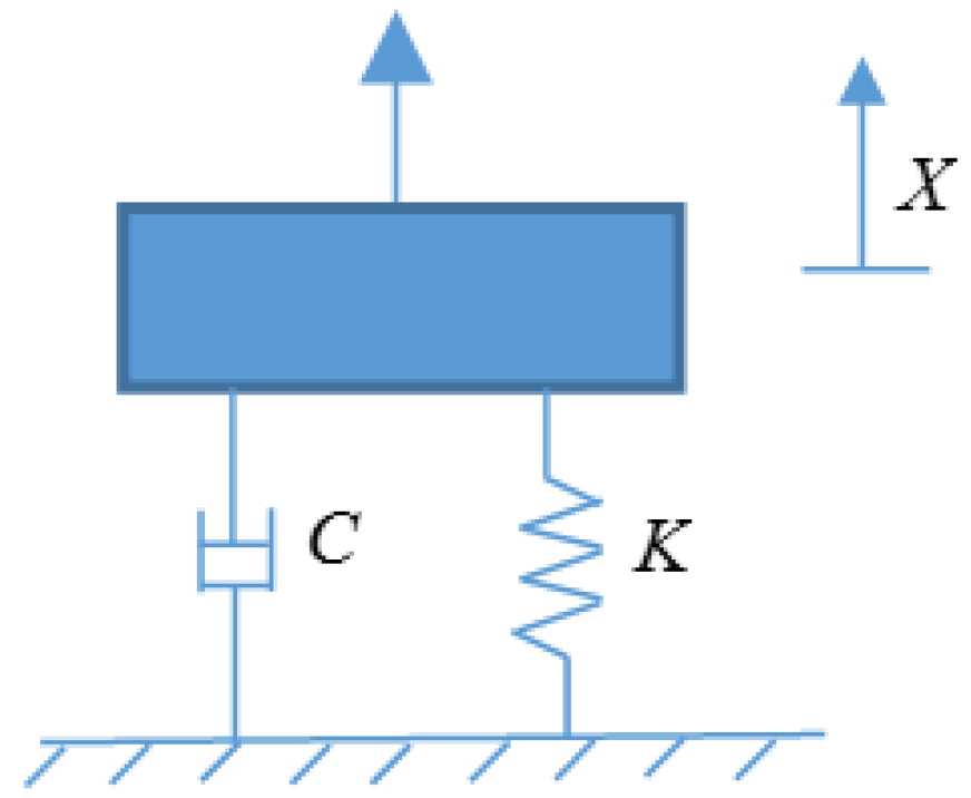
The gas-liquid coupling, dual-chamber, air spring energy-absorbing device has two chambers. The upper chamber functions for air storage and has a fixed volume, while the volume of the lower chamber, in contact with the water, varies with the motion of the water column. The gas and the oscillating liquid column are coupled and this device uses the interaction of oscillations of the liquid column and gas to achieve floating structure motion suppression.
The performance and design of the dual-chamber air spring device are usually modeled after a spring damper system. The characteristics of the damping device are described by the spring stiffness and damping coefficient [26,27,28,29,30]. In this work, the dual-chamber air spring device is a complex fluid-gas coupling system, but its dynamic behavior can also be characterized by the spring stiffness and damping coefficient. The physical model of the common spring damping system can be described using a parallel model or as a series model. Here, we explore the advantages and disadvantages of the two models to characterize the dynamic characteristics of the dual-chamber air spring device applied to motion suppression of marine structures.
In this section, three kinds of energy dissipation expression are derived: a series model, a parallel model, and work done by excitation force.

2.1. Parallel Model

As shown in Figure 2, the standard equation of the model is:
M X ¨ + C X ˙ + K X = F
where M represents the overall mass of the vibration absorber structure, C represents the overall damping of the structure, and K refers to the overall stiffness of the structure.
The structure stiffness in the above equation changes with the air pressure in the vibration absorber air chamber. The change in air pressure is caused by the relative motion of the liquid column in the air chamber. The damping has two components. Some damping is due to fluid vortex shedding at the bottom of the vibration absorber and the friction between the outer wall and water and this damping is related to the motion of the vibration absorber structure. Damping is also caused by the effect of the air in the air chamber and the orifice as well as the friction between inner wall and water, and this damping is related to the motion of the liquid column in the vibration absorber to the vibration absorber.
For harmonic excitation F = F 0 e i ω t , the structural response X is also a harmonic motion which can be represented as X = X 0 e i ( ω t φ ) , substituted into Equation (1) and using Euler′s Formula, e i φ = cos φ + i sin φ , the stiffness and damping of the vibration system can be written as:
K = F 0 X 0 cos φ + ω 2 M
C = 1 ω F 0 X 0 sin φ
The mass matrix can be M = [ m 1 , m 2 , m 3 , m 4 , m 5 , m 6 , m 7 ] T . In the experiment, the mass of each different air chamber length structure is shown as follows:
m 1 = 5.769 , m 2 = 5.967 , m 3 = 6.178 , m 4 = 6.386 , m 5 = 6.593 , m 6 = 6.773 , m 7 = 7.001 , in kg.
The periodical energy consumption of damping is:
Q = C X ˙ d X = 0 T ( C X ˙ ) X ˙ d t = 0 T C X ˙ 2 d t = C 0 T X ˙ 2 d t = 1 ω F 0 X 0 sin φ i = 1 i = f s T X ˙ i 2 t i
where fs refers to the sampling frequency of the experiment, fs = 1024 Hz. Due to the equal-interval sampling of the experiment data, t i = 1 1024 .

2.2. Series Model

As shown in Figure 3, the standard equation of the model is:
{ M X ¨ + k ( X x ) = F k ( x X ) + c x ˙ = 0
Substitute F = F 0 e i ω t and X = X 0 e i ( ω t φ ) into the equation and apply Euler′s Formula, e i φ = cos φ + i sin φ , to determine the damping and stiffness:
c = F 0 ω X 0 sin φ + F 0 ω X 0 cot φ cos φ + 2 ω M cot φ + ω 3 M 2 X 0 F 0 sin φ
k = c 1 ω cot φ + ω M X 0 F 0 sin φ
The periodical energy consumption of damping is:
q = c x ˙ d x = 0 T c x ˙ 2 d t = i = 1 i = f s T c x ˙ i 2 t i

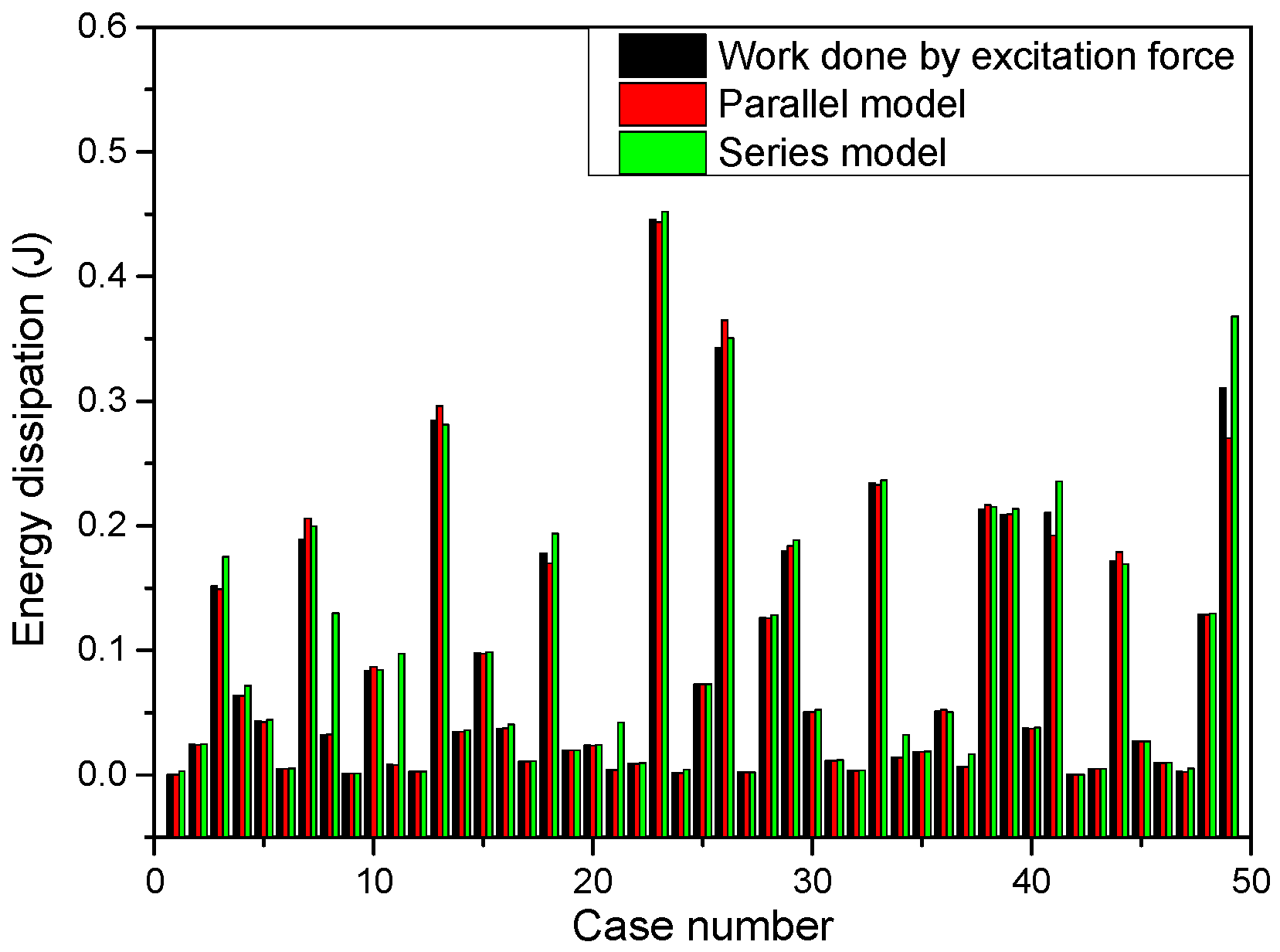
2.3. Work Done by Excitation Force

The periodical work done by excitation force of the system is:
W = F d X = 0 T F X ˙ d t = i = 1 i = f s T F i X ˙ i t i
where F refers to the excitation load, and X refers to the structural response.

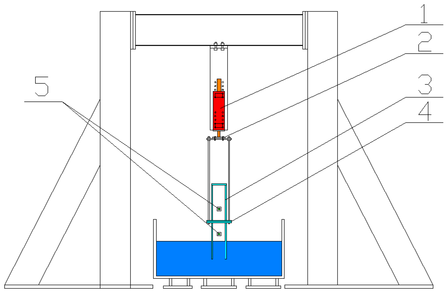
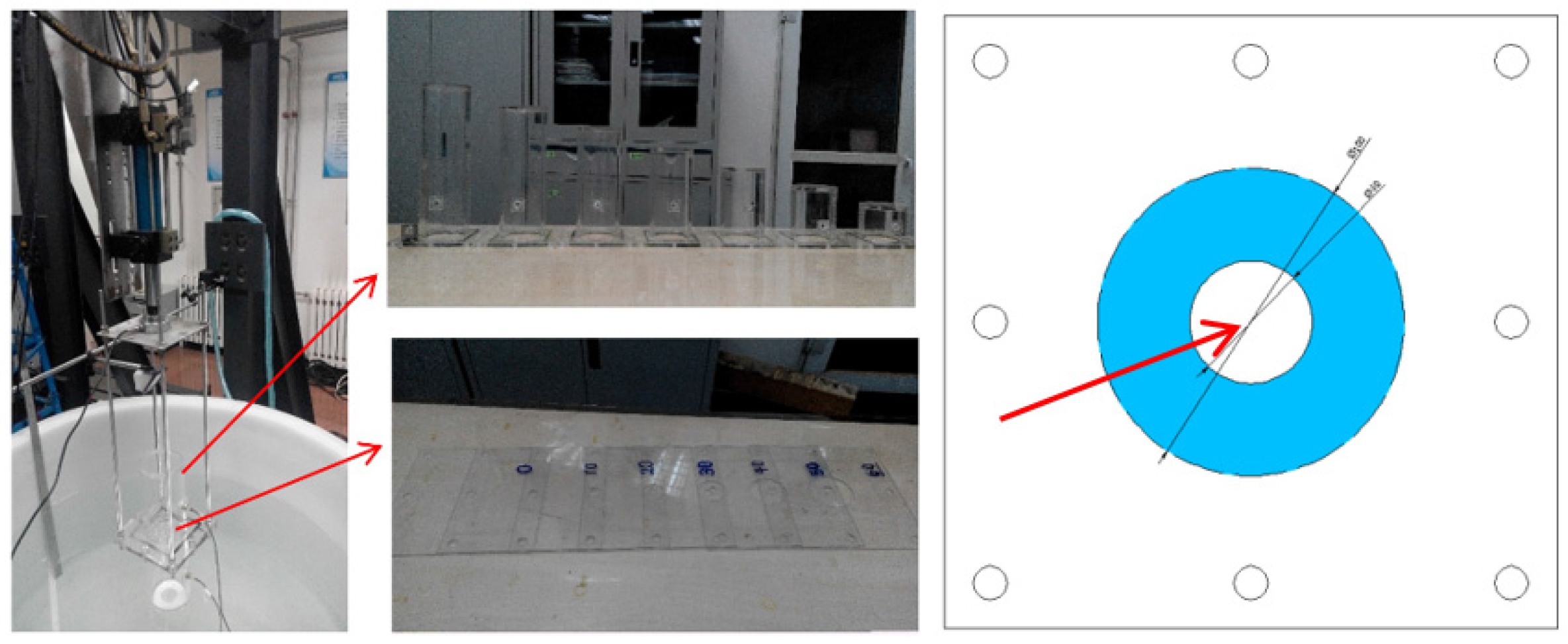
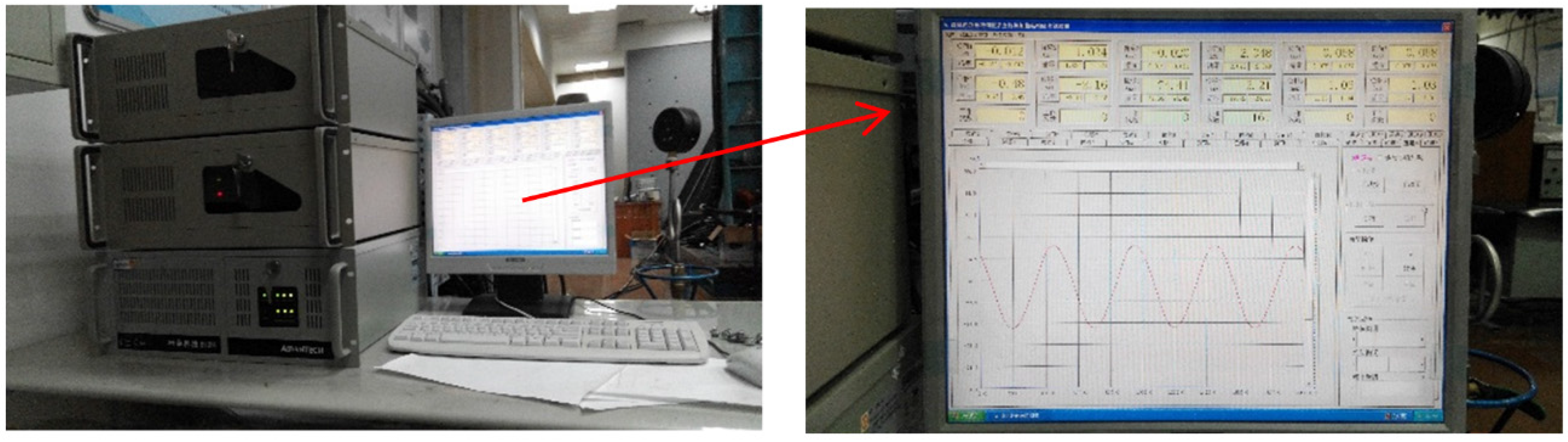
3. Experimental Method

3.1. Design of Experimental Device

The dual-chamber air spring vibration absorber described here is mainly used to restrain the large vibration of an offshore structure. In the experiment, a large water container was designed to simulate the action of sea water. The container is a cylindrical device with a diameter of 1500 mm (much larger than the diameter of 100 mm of the air chamber). As shown in Figure 4, the experimental device consists of: 1. Hydraulic pressure loader; 2. Force sensor; 3. Dual-chamber air spring; 4. Orifice plate; and 5. Air pressure sensor.
As shown in Figure 5, in order to study the effects of different upper and lower air chamber ratios on the vibrating characteristics, the length of the lower air chamber (200 mm) was kept constant while the upper air chamber was changed(100 mm, 150 mm, 200 mm, 250 mm, 300 mm, 350 mm, 400 mm) to study the effect of different volume ratios. The upper and lower air chambers are connected by an orifice plate and the air flows back and forth through an orifice. The orifice changes the air distribution of the chambers greatly and can influence the vibrating characteristics of the structure. In this experiment, the orifice diameters used to study the effect of different orifice ratios on the air spring were 0, 10, 20, 30, 40, 50, and 60 mm.
As shown in Figure 6, a hydraulic servo fatigue machine is used as the loading system of the experiment. The fatigue machine has excellent performance and can be used for large structure experiments. By controlling the loading frequency and amplitude, we can test the effect of external load on the vibrating characteristics of the air spring. In the experiment, the amplitude range was 2, 4, 6, 8, 10, 12, and 14 mm, and the frequency range was 0.497–5.474 Hz.

3.2. Setting of Test Parameters

We studied the influences of each factor on dual-chamber air spring dynamic stiffness and damping. The experiment assumes the cross section of the upper air chamber equals that of the lower air chamber.
Variables to be considered: Volume of upper air chamber V2, Volume of lower air chamber V1, opening diameter d, amplitude of outer excitation A, and frequency of outer excitation ω.
The length of the lower air chamber, L1, and the frequency of outer excitation, ω, were used as the basic variables with the following three dimensionless numbers:
Height of lower air chamber L1 = 0.2 m
Diameter of air chamber D = 0.1 m
ξ 1 = L 2 L 1 , volume ratio, values = 0.5, 0.75, 1, 1.25, 1.5, 1.75, 2
ξ 2 = d D , orifice ratio, values = 0, 0.1, 0.2, 0.3, 0.4, 0.5, 0.6
ξ 3 = A L 1 , ratio of the amplitude of outer excitation and the height of air chamber, values = 0.01, 0.02, 0.03, 0.04, 0.05, 0.06, 0.07.
Frequency of outer excitation. Log value lnω was used to investigate the vibrating characteristics of the air spring at low frequency (values = −0.7, −0.3, 0.1, 0.5, 0.9, 1.3, 1.7).
In total, four variables and seven values were tested, as shown in Table 1:

3.3. Orthogonal Experiment and Orthogonal Array

For experimental designs with multiple factors and multiple levels, a large number of experiments are required. For example, for the experimental scheme with four variables and seven levels in this paper, 2401 (74) experiments need to be carried out. Hence, a method with the minimum numbers of experiments is needed to find out the effect of each parameter on the vibrating characteristics of the air spring.
In 1947, Rao [31] developed factorial experiments, an optimization experimental method (an efficient testing strategy) that can determine the relation between factors and a test index and specify the primary and secondary factors using fewer trials. Taguchi [32] effectively used orthogonal arrays in his research. Azouzi and Guillot [33] examined the feasibility for an intelligent sensor fusion to estimate online surface finish and dimensional deviations using orthogonal arrays. Green, Krieger, and Wind [34] applied orthogonal arrays to conjoint analysis. The use of the orthogonal test method minimizes the number of tests but still allows determination of the changing rules of all factors. We applied the orthogonal experiment method to investigate the effect of upper and lower air chamber volume ratio, orifice ratio, loading amplitude, and loading frequency of outer excitation.
As an effective method of solving multi-factor experiment problems, orthogonal experimental design selects typical points from the overall experiment and tests them. These typical points are “even” and “regular”: (1) in the experiment, each factor has the same occurrence number at each different level; (2) each combination of two factors at each different level occurred in the experiment and had the same occurrence number. Meeting these two criteria indicates that the experiment scheme designed by orthogonal experiment method is typical. This method reduces the number of experiments and can generally reflect the overall effect of each factor at each level on the index.
Range analysis is commonly used in scientific experiments. Change in experimental results often occurs in scientific experiments due to two types of factors. One is variations arising from random effects; such effects are controllable in experiments, and are therefore inevitable. The other is artificial control produces changes in experimental results. When such factors have a significant impact on the experiment, they are bound to significantly alter the results, accompanied by random factors. Conversely, when such factors have no significant effect on the experimental results, corresponding changes will not be manifested obviously, so changes in experimental results have been substantially ascribed to the effects of random factors. The purpose of conducting scientific experiments is often to determine whether these artificially controllable factors have an impact on the experimental results and what the effect is.
Range analysis is an effective tool to judge the above matters through analyzing the data variation in experimental results, because it can separate random variation from non-random variation in a hybrid state to help determine the source of dominant variations. Using range analysis, we analyzed the results of orthogonal design to explore the effect of various factors on air spring characteristics. In addition, we investigated the effects of four factors (upper and lower air chamber volume ratio, orifice ratio, loading amplitude, and loading frequency of outer excitation) on the air vibration characteristics of the dual-chamber. Seven variation levels of each factor were examined. The tests were performed 49 times, accounting for only 2% of the traditional number of trials. The arrangements and results of the orthogonal analysis scheme are shown in Appendix 1.

4. Experimental Results and Analysis of a Dual-Chamber Air Spring

We used an intuitive method in orthogonal analysis that looks at means and ranges. The mean average is the average value of different factors at the same level, and this can reveal the effect of different levels of single factors on the indicators. The range indicates the maximum value of the average numerical difference for each factor at each level, and reflects the impact of each column factor at different levels, from which the primary and secondary sequence of factors can be determined. If each factor has the same number of level, the influence extent of each factor can be judged directly by comparing the range size.
For 49 sets of experimental schemes, the comparison of energy dissipation is shown in Figure 7.
Figure 7 shows that under most operating conditions, there is a good fit between the parallel model and work done by excitation force, but under individual conditions, the series model shows better goodness of fit. From the relationship of energy dissipation mean of the 49 sets of orthogonal design schemes,
the goodness of fit of the parallel model α p = 1 0 49 | Q p a r a l l e l Q s t r u c t u r e | Q s t r u c t u r e 49 = 99.88 % .
The goodness of fit of the series model α s = 1 0 49 | Q s e r i e s Q s t r u c t u r e | Q s t r u c t u r e 49 = 89.43 % .
By the range relation of energy consumption, we can infer a higher goodness of fit between work done by excitation force and energy dissipation of the parallel model. Furthermore, the parallel model can be employed to make deeper analyses of the structure.

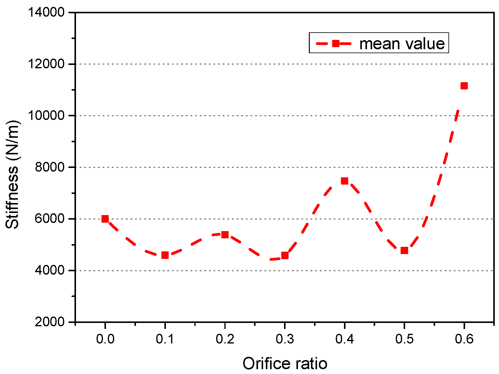
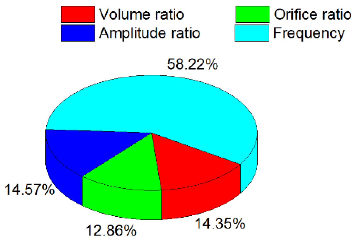
4.1. Influence of Various Parameters on Air Spring Stiffness

Stiffness is a function of the volume ratio, orifice ratio, excitation amplitude, and frequency. The influence law can be seen from the following figures:
As can be seen from Figure 8, the effect of the volume ratio on the dual-chamber vibration absorber stiffness is not monotonic. With an increase in the volume ratio, the stiffness of vibration absorber first slowly decreases and increases at a volume ratio of 1.25, then decreases and finally increases dramatically. As per Figure 9, the effect of the orifice ratio on the dual-chamber vibration absorber stiffness similarly is not monotonic. With an increase in the orifice ratio, the stiffness of vibration absorber first shows little change, then increases at a orifice ratio of 0.4, then decreases and finally increases to its highest level.
According to Figure 10, the effect of the loading amplitude ratio on the dual-chamber vibration absorber stiffness is basically monotonic. With an increase in the amplitude ratio, the stiffness of the dual-chamber air spring also increases and slightly protrudes at the amplitude ratio of 0.04. Figure 11 shows the effect of the loading frequency on the dual-chamber vibration absorber stiffness is also monotonic. The stiffness of the dual-chamber air spring monotonically increases with an increase in the loading frequency. As can be seen from Figure 12, the effect of each factor on the dual-chamber vibration absorber stiffness varies, where the volume ratio, orifice ratio, and loading amplitude ratio exert considerable influence but the loading frequency has the maximum impact. The results described in Figure 12 are only applicable when considering the volume ratio, the orifice ratio, load amplitude, and frequency in this case.

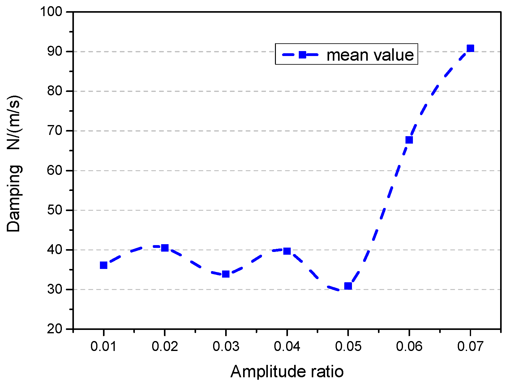
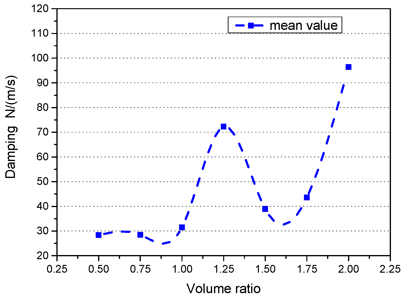
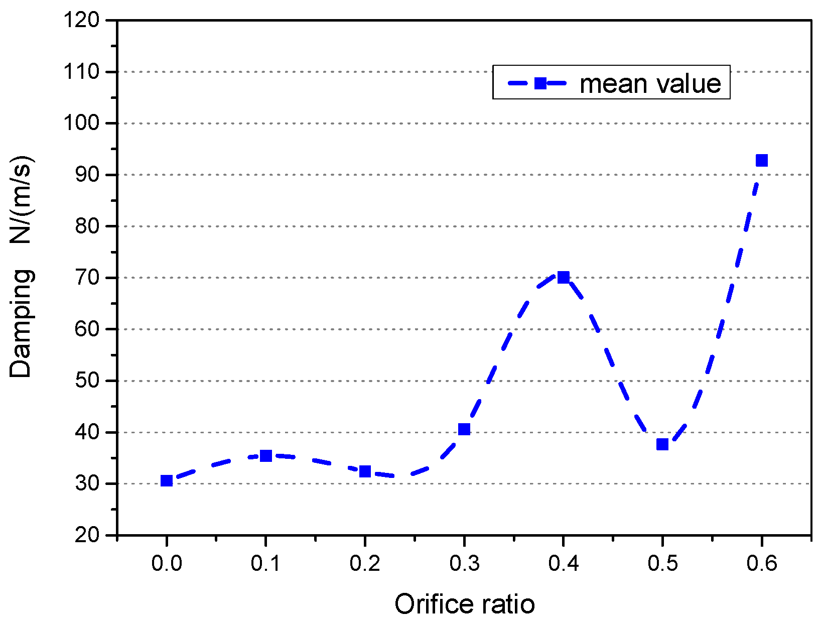
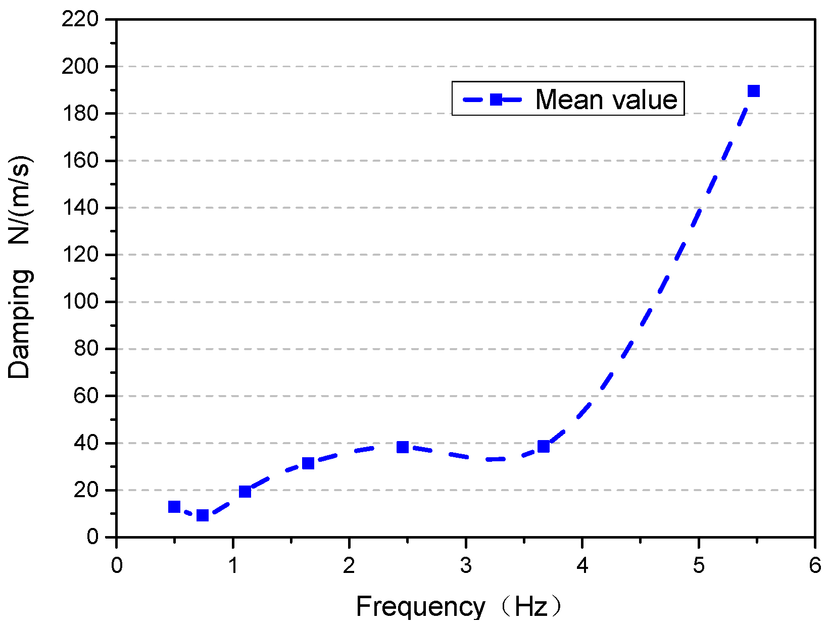
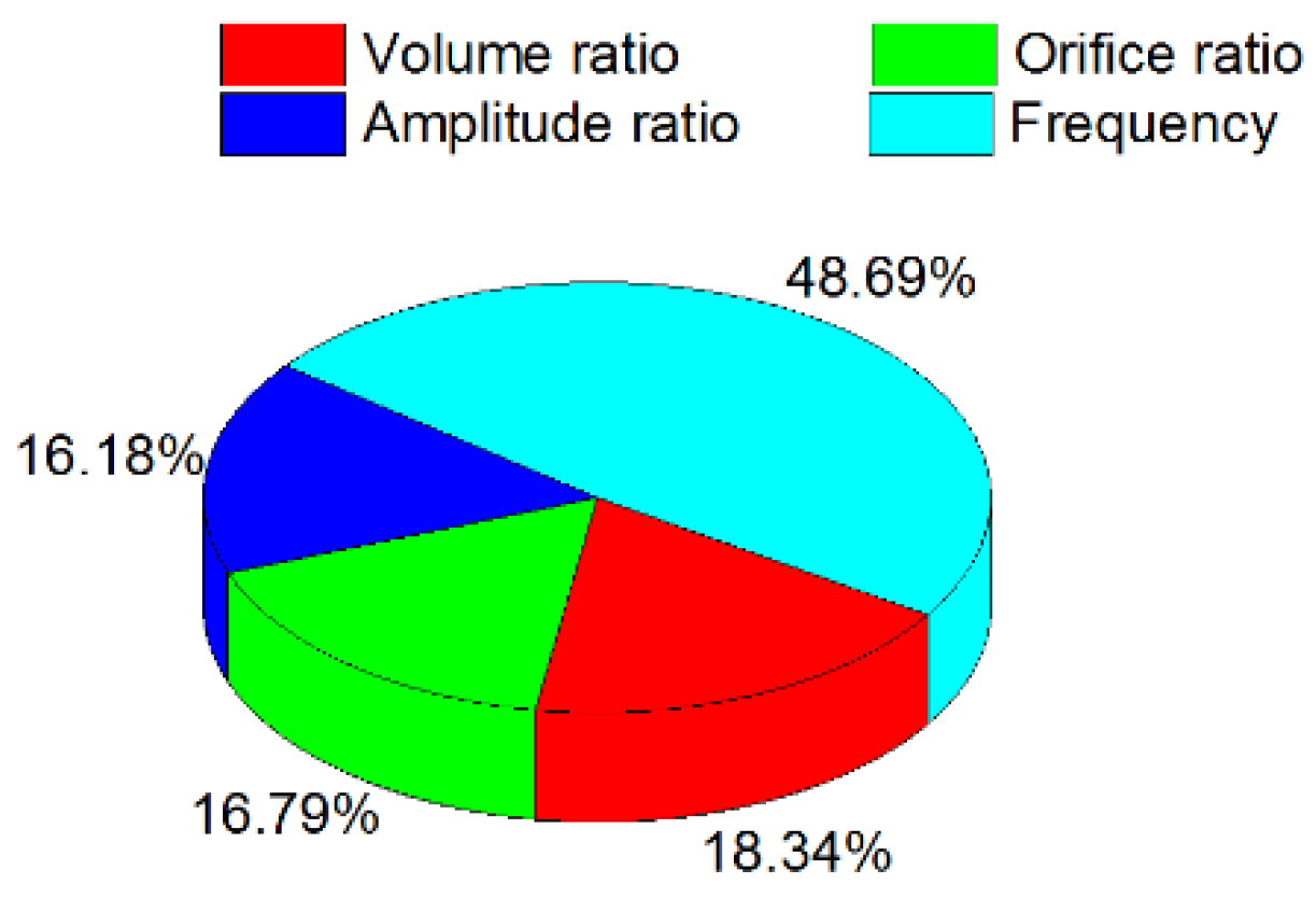
4.2. Influence of Various Parameters on Air Spring Damping

Damping is a function of the volume ratio, orifice ratio, excitation amplitude, and frequency. In this section the four factors for the dual-chamber air spring damping effects are examined.
The influence law can be seen from the following figures:
Figure 13 shows that the effect of the volume ratio of the dual-chamber vibration absorber damping is not monotonic. With an increase in the volume ratio, the damping of the vibration absorber first slowly decreases and then increases at a volume ratio of 1.25, then decreases and then increases. As per Figure 14, the effect of the orifice ratio on the dual-chamber vibration absorber damping is also not monotonic. With an increase in the orifice ratio, the damping of vibration absorber first shows little change, then increases at an orifice ratio of 0.4, then decreases and then increases.
According to Figure 15, the effect of the loading amplitude ratio on the dual-chamber vibration absorber damping is not monotonic. With an increase in the amplitude ratio, the structural damping shows little change at first and then declines at 0.05, before eventually increasing. Figure 16 indicates that the effect of the loading frequency on the dual-chamber vibration absorber damping is basically monotonic. With an increase in the amplitude ratio, the vibration absorber damping increases until 3.669 Hz, and then increases dramatically. As summarized in Figure 17, the effect of each factor on the dual-chamber vibration absorber damping varies, where the volume ratio, orifice ratio, and loading amplitude ratio have strong effects but the loading frequency has the maximum impact. The results described in Figure 17 are only applicable when considering the volume ratio, the orifice ratio, load amplitude, and frequency in this case.
Thus, the four factors influence the stiffness and damping of the gas-liquid coupling dual-chamber air spring in a complex manner; there is not a simple linear relationship. Each factor has different effects on stiffness and damping. Prediction of the effects on stiffness and damping of the gas-liquid coupling dual-chamber air spring based on these four factors would be useful for efficient design, and in the next chapter, we propose an efficient model of dual-chamber air spring stiffness and damping to do this.

5. Rapid Calculation Model of Dual-Chamber Air Spring Stiffness and Damping

From the previous analyses, we can see that volume ratio, orifice ratio, loading amplitude, and loading frequency all have complex effects on the stiffness and damping of the dual-chamber air spring device and are not monotonic in most cases. Therefore complex models must be constructed using statistical analyses of the experimental data.

5.1. Normalization Process of Each Factor

In order to facilitate the analysis of each factor′s effect, the normalization process of each factor is performed.
Normalized volume ratio φ 1 = ξ 1 2 , values of 0.25, 0.375, 0.5, 0.625, 0.75, 0.875, 1.
Normalized orifice ratio φ 2 = ξ 2 0.6 , values of 0, 0.167, 0.333, 0.5, 0.667, 0.833, 1.
Normalized loading amplitude ratio φ 3 = ξ 3 0.07 , values of 0.142, 0.286, 0.429, 0.571, 0.714, 0.857, 1.
Normalized loading frequency φ 4 = lnω + 0.7 2.4 , values of 0, 0.167, 0.333, 0.5, 0.667, 0.833, 1.
The functional relationship between the stiffness and damping of the dual-chamber air spring and each factor is:
K modle = f 1 ( φ 1 , φ 2 , φ 3 , φ 4 )
C modle = f 2 ( φ 1 , φ 2 , φ 3 , φ 4 )

5.2. Determination of Rapid Calculation Model of Stiffness and Damping

From the above analysis, each factor has a nonlinear impact on the stiffness and damping of the dual-chamber air spring. The quadratic function can not accurately simulate the variation law of the stiffness and damping of the dual-chamber air spring. When the power of an independent variable is more than three, the regression function becomes very unstable [35], thus destabilizing the application of the regression model. In order to more accurately reflect the effect law of each factor on the stiffness and damping of the dual-chamber air spring, this paper uses cubic polynomials, which can usually be converted into ordinary multiple linear regression for processing. Experimental data are used to fit the expression of the stiffness and damping of the dual-chamber air spring.
Suppose the stiffness experimental value meets the following cubic polynomials:
f 1 = β 0 + j = 1 34 β j g j ( φ 1 , φ 2 , φ 3 , φ 4 ) = β 0 + β 1 φ 1 + β 2 φ 2 + β 3 φ 3 + β 4 φ 4 + β 5 φ 1 2 + β 6 φ 2 2 + β 7 φ 3 2 + β 8 φ 4 2 + β 9 φ 1 φ 2 + β 10 φ 1 φ 3 + β 11 φ 1 φ 4 + β 12 φ 2 φ 3 + β 13 φ 2 φ 4 + β 14 φ 3 φ 4 + β 15 φ 1 3 + β 16 φ 2 3 + β 17 φ 3 3 + β 18 φ 4 3 + β 19 φ 1 2 φ 2 + β 20 φ 1 2 φ 3 + β 21 φ 1 2 φ 4 + β 22 φ 1 φ 2 2 + β 23 φ 1 φ 3 2 + β 24 φ 1 φ 4 2 + β 25 φ 2 2 φ 3 + β 26 φ 2 2 φ 4 + β 27 φ 2 φ 3 2 + β 28 φ 2 φ 4 2 + β 29 φ 3 2 φ 4 + β 30 φ 3 φ 4 2 + β 31 φ 1 φ 2 φ 3 + β 32 φ 1 φ 2 φ 4 + β 33 φ 1 φ 3 φ 4 + β 34 φ 2 φ 3 φ 4 + ε i ( o 4 )
where β 0 , β 1 , β 2 , .... , β 34 are undetermined coefficients; φ 1 , φ 2 , φ 3 , φ 4 are controllable variables in the experiment; g j ( φ 1 , φ 2 , φ 3 , φ 4 ) is function expression corresponding to β j ; and f 1 is the stiffness of dual-chamber air spring.
This paper uses the least squares method to estimate the undetermined coefficients in the above formula to obtain the regression equation for stiffness:
f ^ 1 E 13 = 0.0952 + 1.4139 φ 1 0.6852 φ 2 1.3314 φ 3 + 1.2366 φ 4 0.9296 φ 1 2 + 0.5123 φ 2 2 + 0.3488 φ 3 2 0.7531 φ 4 2 0.3542 φ 1 φ 2 0.7975 φ 1 φ 3 1.5502 φ 1 φ 4 + 2.7841 φ 2 φ 3 0.5386 φ 2 φ 4 + 0.2573 φ 3 φ 4 0.1684 φ 1 3 0.5071 φ 2 3 + 1.4815 φ 3 3 0.2310 φ 4 3 + 0.8761 φ 1 2 φ 2 + 1.3092 φ 1 2 φ 3 + 0.1184 φ 1 2 φ 4 0.0996 φ 1 φ 2 2 0.3868 φ 1 φ 3 2 + 0.0888 φ 1 φ 4 2 + 1.1500 φ 2 2 φ 3 0.6931 φ 2 2 φ 4 2.5784 φ 2 φ 3 2 + 0.1512 φ 2 φ 4 2 2.7151 φ 3 2 φ 4 + 1.6950 φ 3 φ 4 2 2.1074 φ 1 φ 2 φ 3 + 1.1258 φ 1 φ 2 φ 4 + 1.3134 φ 1 φ 3 φ 4 + 0.6595 φ 2 φ 3 φ 4
Similarly, the damping regression equation can be acquired based on the stiffness calculation method:
f ^ 2 E 11 = 0.2648 + 3.0819 φ 1 1.6038 φ 2 2.5479 φ 3 + 2.5604 φ 4 2.1802 φ 1 2 + 1.4020 φ 2 2 + 1.5283 φ 3 2 1.6530 φ 4 2 0.8512 φ 1 φ 2 1.5508 φ 1 φ 3 3.7226 φ 1 φ 4 + 5.4696 φ 2 φ 3 0.8495 φ 2 φ 4 + 0.0787 φ 3 φ 4 0.1734 φ 1 3 0.9562 φ 2 3 + 1.4337 φ 3 3 0.2797 φ 4 3 + 1.6602 φ 1 2 φ 2 + 2.1616 φ 1 2 φ 3 + 0.8800 φ 1 2 φ 4 0.1481 φ 1 φ 2 2 0.3982 φ 1 φ 3 2 + 0.6600 φ 1 φ 4 2 + 0.9527 φ 2 2 φ 3 0.8391 φ 2 2 φ 4 3.9493 φ 2 φ 3 2 + 0.4225 φ 2 φ 4 2 3.5250 φ 3 2 φ 4 + 2.5354 φ 3 φ 4 2 3.3547 φ 1 φ 2 φ 3 + 1.6821 φ 1 φ 2 φ 4 + 1.9625 φ 1 φ 3 φ 4 + 0.3758 φ 2 φ 3 φ 4
Then the stiffness and damping of the dual-chamber air spring can be calculated by the following formulas:
K modle = f 1 ( φ 1 , φ 2 , φ 3 , φ 4 ) = f ^ 1 E 13
C modle = f 2 ( φ 1 , φ 2 , φ 3 , φ 4 ) = f ^ 2 E 11
Equations (15) and (16) determine the cubic polynomial equation of stiffness and damping.

5.3. Test of Calculation Model

In statistics, regression analysis is performed using the variables. The coefficient of determination. R2 is the ratio between the regression sum of squares and sum of squares for total. R2 is between 0 and 1. The closer it is to 1, the better the fit of the regression. A goodness of fit of more than 0.8 is typically considered acceptable.
In multiple regression analysis, R2 expression:
R 2 = 1 S S E S S T
where SST is the sum of squares for total; and SSE is the sum of squares for error.
S S T = i = 1 N ( f 1 i f ¯ 1 i ) 2
S S E = i = 1 N ( f 1 i f ^ 1 i ) 2
The coefficient of determination R2 is related to the number of independent variables. In order to accurately test the accuracy of the model, it is necessary to take into account the degrees of freedom and make adjustments of R2 expression according to the size of the formula.
R a 2 = 1 S S E / ( n p 1 ) S S T / ( n p ) = 1 ( 1 R 2 ) ( n 1 n p 1 )
Ra2 is denoted as the adjusted coefficient of determination; n is the total number of experiments, and p is the number of variables. The adjusted coefficient of determination more accurately reflects the degree of fit between the model and experimental data.
By making an analysis of the data (n = 49, p = 35), the following can be obtained:
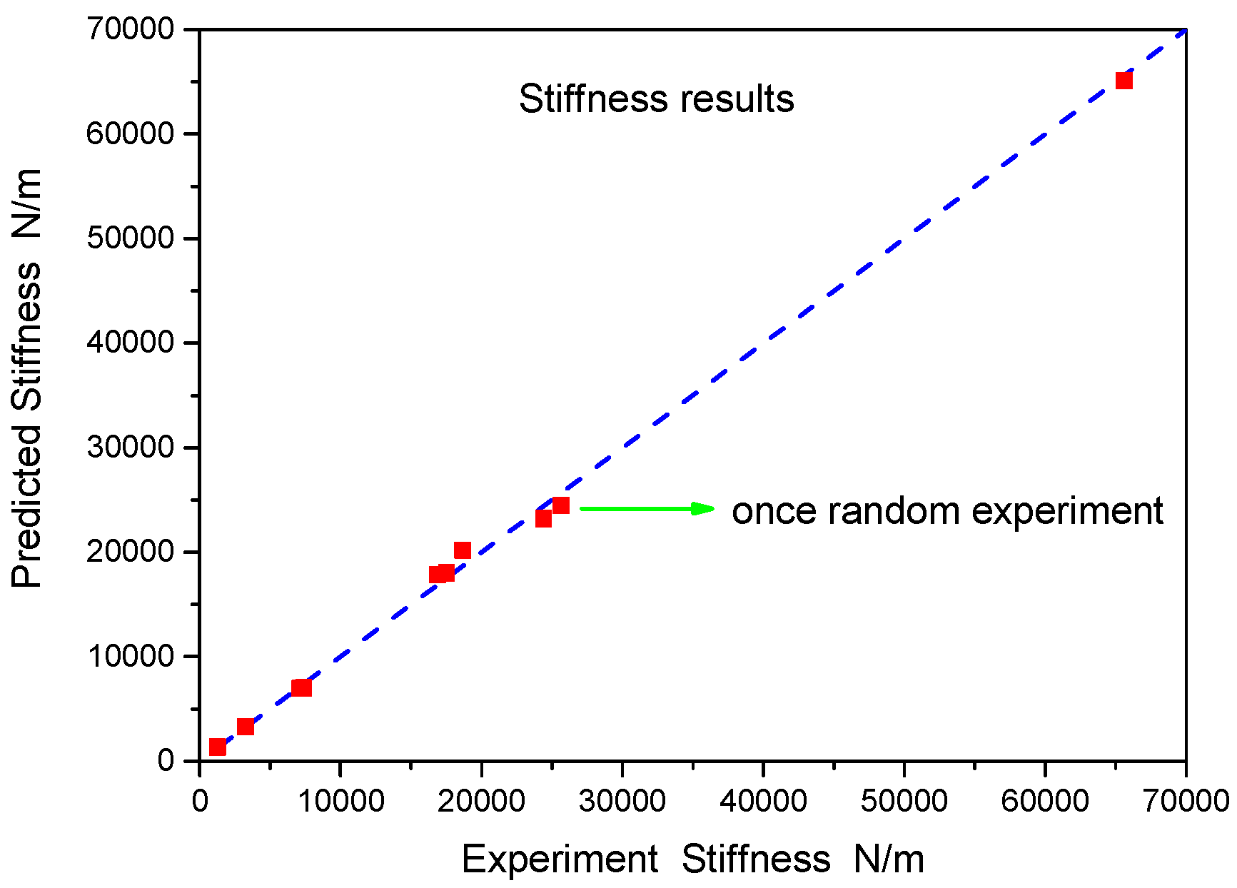
  • For the stiffness model R2 = 0.99154, Ra2 = 0.96378, the goodness of fit is 96.378%, indicating that the model can well simulate and predict the experimental results. This indicates the effectiveness of the cubic polynomial regression equation fit.
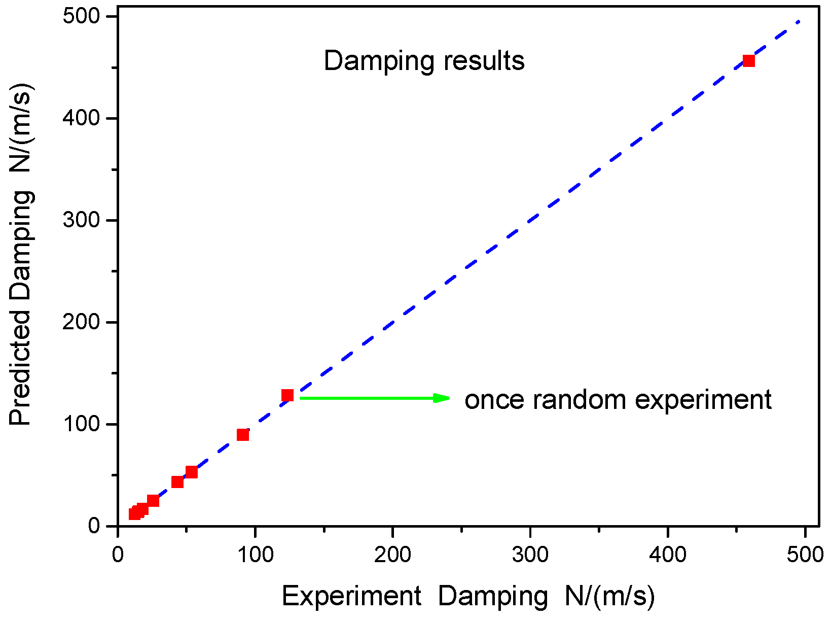
  • For the damping model, R2 = 0.98970, Ra2 = 0.95470, the goodness of fit is 95.470%, again indicating that the model can well simulate and predict the experimental results. This again supports the effectiveness of the cubic polynomial regression equation fit.

5.4. Prediction of Experimental Results by the Rapid Calculation Model

To further validate the forecast accuracy of the stiffness and damping rapid calculation model, we conducted a series of experiments. To ensure the universality, these experiments consist of random combinations of four factors at different levels, different from the levels tested in the test programs in the orthogonal table.
The straight lines in Figure 18 and Figure 19 are experimental values, while red dots are predictive values for the rapid calculation model. If a dot falls on the line, this indicates the predicted value is equivalent to the experimental value; deviations from the straight line indicate differences between the predicted and the experimental values. As seen in the figures, the predicted and experimental values fit well. For more horizontal level combination schemes, the predicted value can be calculated based on the rapid calculation model proposed in this paper, which can play a guiding role to engineering structural design and applications.
The experiments performed here were representative in the parameter range, and the polynomial prediction model is appropriate for these values. The application of the polynomial prediction model is as follows: upper and lower air chamber volume ratio, ξ 1 [ 0.5 2.0 ] , orifice ratio, ξ 2 [ 0 0.6 ] , loading amplitude ratio, ξ 3 [ 0.01 0.07 ] , and loading frequency f [ 0.497 5.474 ] .

6. Conclusions

The mechanical differences between the gas-liquid coupling dual-chamber air spring device and the traditional one make the analysis of effects on stiffness and damping more challenging. The compression of the gas in the traditional air spring is directly on the external load of the air chamber by the piston. The pressure variation of the air spring chamber is the same phase and amplitude as the external load, but for the dual-chamber air spring device applied to motion suppression of marine structures, the movement of the liquid column and the external excitation differ in phases and amplitude.
The current study analyzes the characteristics of a dual-chamber air spring device. A parallel model and series model were used to simulate the dual-chamber air spring energy-absorbing device. An orthogonal test scheme was used to investigate the effect laws of four factors (upper and lower air chamber volume ratio, orifice ratio, loading amplitude, and loading frequency of outer excitation) on the air vibration characteristics of the dual-chamber. Based on the experimental results, a higher-order non-linear regression method was obtained, achieving a rapid calculation model for dual-chamber air spring stiffness and damping, and the reliability of the method was verified experimentally. Using the rapid calculation model, from the upper and lower air chamber volume, orifice ratio, the frequency, and amplitude of external load, we can determine the stiffness and damping of the dual-chamber air spring device applied to motion suppression of marine structures by the formulas (15) and (16). The main findings are:
  • Based on energy consumption results, the goodness of fit of the parallel model was 89.43%, and the goodness of fit of the series model was 99.88%. The parallel model is more consistent with the real physical model.
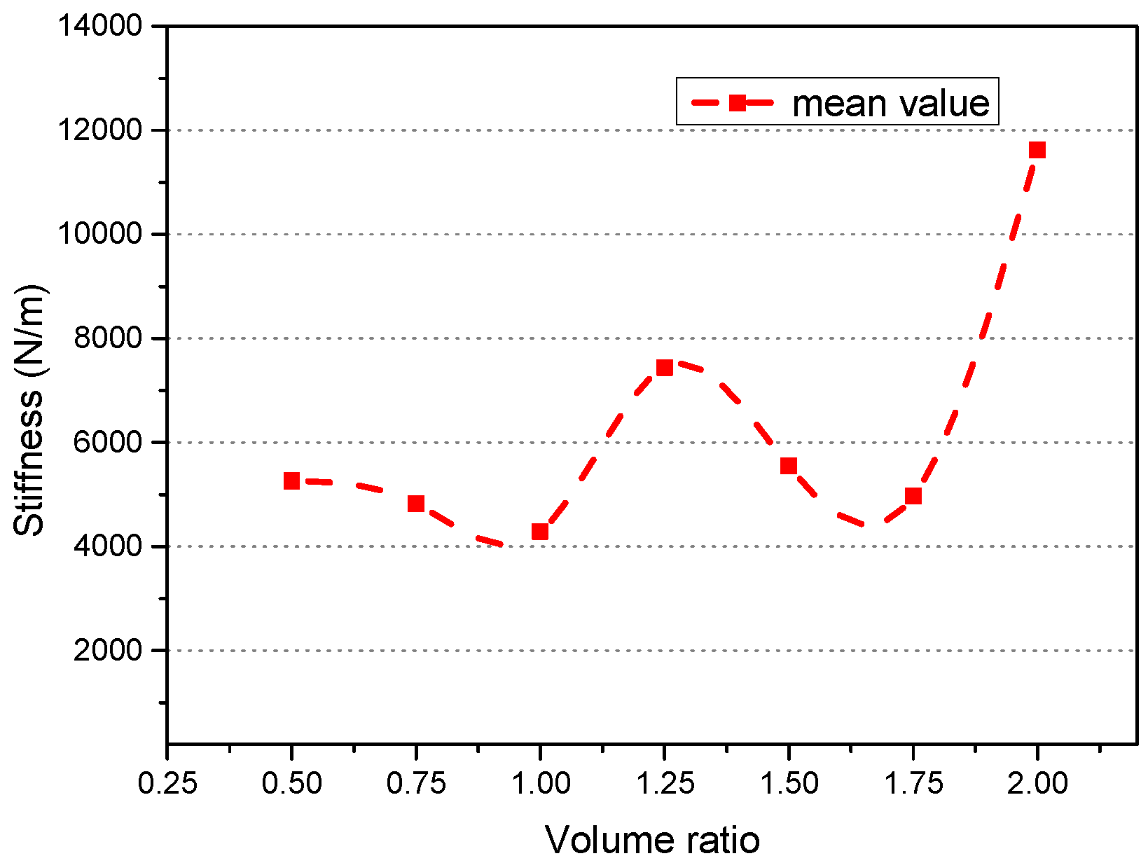
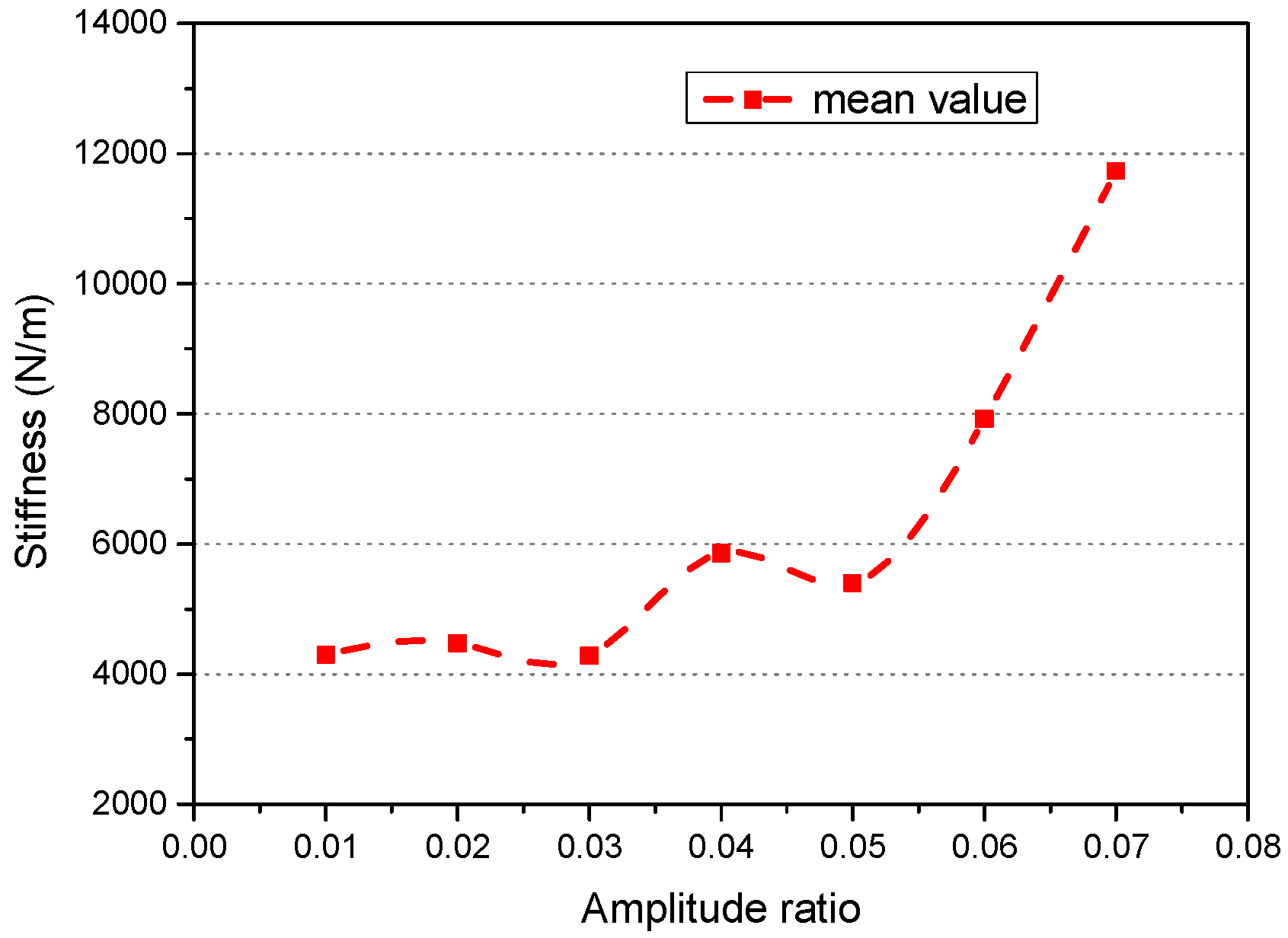
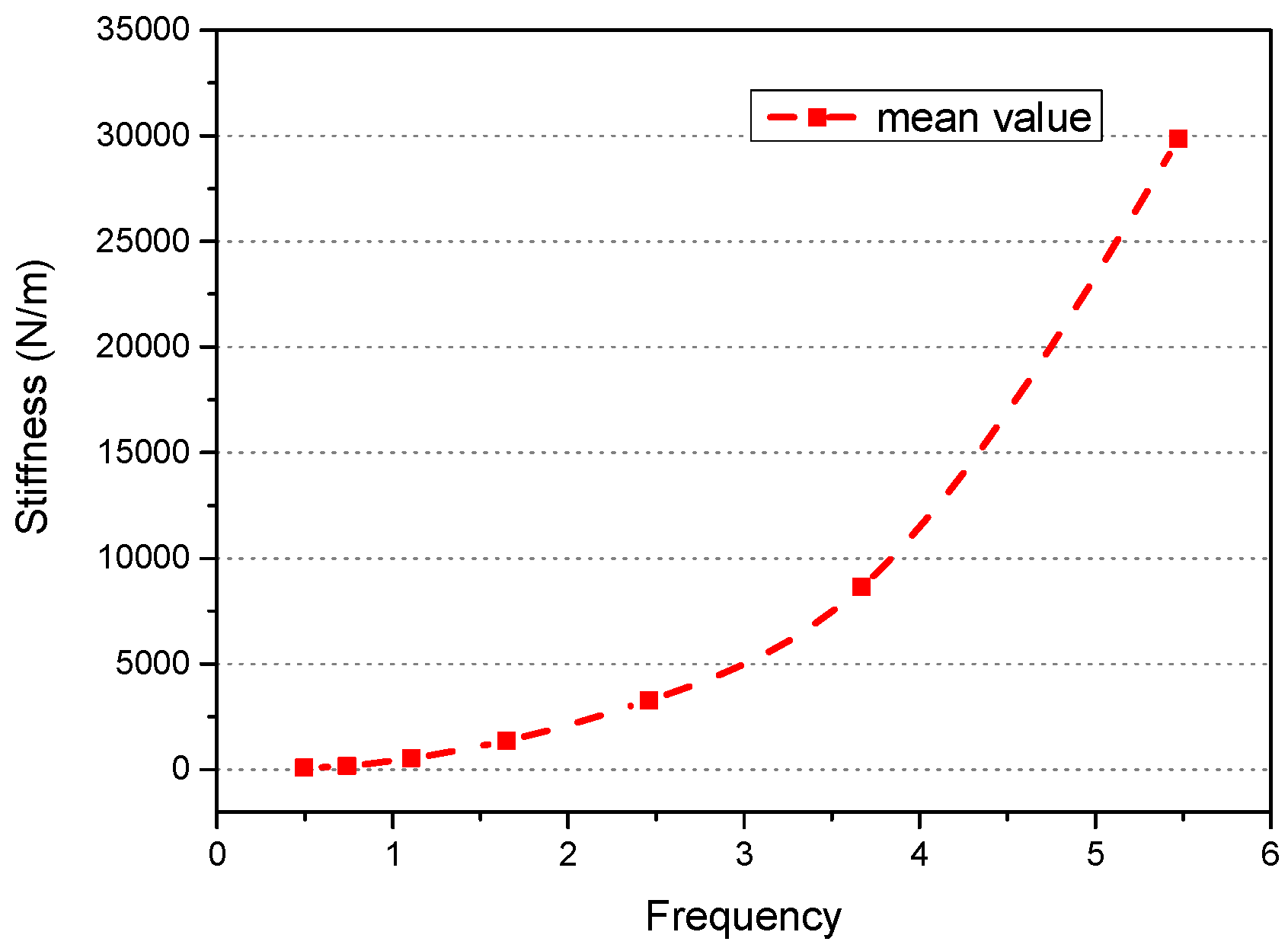
  • The effects of volume ratio and orifice ratio on dual-chamber vibration absorber stiffness were not monotonic, but the loading amplitude ratio and frequency tended toward monotonic increasing.
  • The effects of the volume ratio, orifice ratio, and loading amplitude ratio on the dual-chamber vibration absorber stiffness did not behave in a monotonic manner, but the loading frequency on damping tended toward monotonic increasing.
  • A polynomial rapid calculation model for stiffness and damping was constructed. The accuracy of the rapid calculation model results was verified by the experimental results, and the predicted values were in good agreement with the experimental values.

Acknowledgments

The authors would like to express their gratitude for the financial support of the National Natural Science Foundation of China (Grant Nos. 11072246, 51490673, 10702073, 11232012) and the National Basic Research Program of China (973 Program 2014CB046801)

Author Contributions

Xiaohui Zeng put forward the overall idea. Liang Zhang contributed to the theoretical and experimental analysis, and wrote the manuscript. Yang Yu contributed to the experimental study. Min Shi contributed to data analysis. Jifu Zhou contributed to data analysis.

Conflicts of Interest

The authors declare no conflict of interest.

Appendix

Table A1. Orthogonal table L49 and the experimental analysis results.
CaseVolume Ratio ( ξ 1 ) Orifice Ratio ( ξ 2 ) Loading Amplitude Ratio ( ξ 3 ) Loading Frequency ln ω Real Loading Frequency (Hz)Parallel ModelSeries ModelWork Done by Excitation Force
KCQkcqW
10.500.01−0.70.497109.19214.7720.0004292128.62797.7660.0030810.0004297
20.50.10.030.51.6491249.03519.8700.024111282.923752.2370.024830.02437
30.50.20.051.75.47424512.04758.1060.149224674.8238808.2500.17520.1516
40.50.30.070.11.105503.28515.4000.06352525.984356.8540.071560.06384
50.50.40.021.33.6697208.51347.0430.042467371.5262127.2920.044340.04304
60.50.50.04−0.30.741158.2237.2490.005029165.412166.8010.0051020.005048
70.50.60.060.92.4603121.94936.4500.20583223.4871157.1790.19960.1887
80.7500.071.33.66910804.93510.7710.0324910810.63620423.0490.12990.03209
90.750.10.02−0.30.741152.9255.9890.001248158.002186.4030.0013310.001287
100.750.20.040.92.4603298.78235.0560.086773387.6641336.1230.084470.08329
110.750.30.06−0.70.49798.9088.2650.008236105.624129.9700.097430.008478
120.750.40.010.51.6491277.19020.4700.0028321312.362763.7840.0029480.002881
130.750.50.031.75.47417619.902102.9520.296218330.7712654.7750.28120.2846
140.750.60.050.11.105519.75115.9300.03474543.270367.9700.035930.03468
15100.060.51.6491412.35224.3680.097381457.423787.9550.098710.09771
1610.10.011.75.47417009.60098.2640.0374317680.4322589.8380.040810.0374
1710.20.030.11.105561.65016.7140.01086585.609408.5240.011110.01092
1810.30.051.33.6697642.98836.2050.177734.0533074.8200.19370.178
1910.40.07−0.30.741179.2278.0040.02186.963193.4290.020070.02
2010.50.020.92.4603121.60328.2480.023713182.5901474.0950.024130.02384
2110.60.04−0.70.49799.4298.5660.004021106.606127.2370.042110.004046
221.2500.05−0.30.741175.5387.1000.00899181.754207.6080.0097730.009058
231.250.10.070.92.4603294.97145.8010.44363446.8671039.3280.4520.446
241.250.20.02−0.70.49793.41719.1460.001581131.58066.0130.0042690.001549
251.250.30.040.51.6491337.61035.0920.072921436.307510.6850.072930.07287
261.250.40.061.75.47439581.430324.9460.36542733.8984404.8650.35080.3427
271.250.50.010.11.105507.80426.2410.002135573.125230.2410.0021080.002117
281.250.60.031.33.6697085.17547.5000.12587254.2632037.8390.12850.1262
291.500.041.75.47425749.741114.5650.18426352.0965012.0480.18850.1795
301.50.10.060.11.105578.65117.7410.05048604.853409.5430.052460.05053
311.50.20.011.33.6697492.06334.7810.011397577.8013074.0690.011960.0116
321.50.30.03−0.30.741191.8488.8070.003483200.600201.8810.0035910.003496
331.50.40.050.92.4603380.53047.5340.23293540.0011055.1890.23640.2345
341.50.50.07−0.70.49783.22214.3370.01418107.24264.0090.032120.01412
351.50.60.020.51.6491376.69434.9540.018571471.837540.7320.018810.01865
361.7500.030.92.4603187.45727.9380.052433245.8801552.1700.050430.05119
371.750.10.05−0.70.49785.25912.1300.006464102.04373.7470.016770.006484
381.750.20.070.51.6491529.73246.2050.21681679.347518.6260.21520.2133
391.750.30.021.75.47418778.734133.3340.209419897.4932371.3910.21370.2089
401.750.40.040.11.105573.19929.0530.03713644.131263.8250.038140.03742
411.750.50.061.33.66910461.16045.5200.192110566.3324573.2060.23580.2106
421.750.60.01−0.30.741174.02610.8790.0004944188.745139.5010.00048850.0004824
43200.020.11.105564.64514.6960.005067583.071465.0620.0050490.005031
4420.10.041.33.6699798.21248.0730.1799923.4523809.1070.16930.1718
4520.20.06−0.30.741198.35716.8580.02693229.366124.6920.026890.02692
4620.30.010.92.4603509.96947.1400.0098063661.0211142.5280.0099240.009847
4720.40.03−0.70.49783.85113.4580.002517104.85767.1780.0053970.002638
4820.50.050.51.6491490.13439.1470.12861600.387568.2450.12970.129
4920.60.071.75.47465716.150495.1440.270370124.8597875.7530.3680.3109

References

  1. Taylor, R.E.; Jefferys, E.R. Variability of hydrodynamic load predictions for a tension leg platform. Ocean Eng. 1986, 13, 449–490. [Google Scholar] [CrossRef]
  2. Zeng, X.H.; Shen, X.P.; Wu, Y.X. Governing equations and numerical solutions of tension leg platform with finite amplitude motion. Appl. Math. Mech. 2007, 28, 37–49. [Google Scholar] [CrossRef]
  3. Zeng, X.H.; Li, X.W.; Liu, Y.; Wu, Y.X. Nonlinear dynamic responses of tension leg platform with slack-taut tether. China Ocean Eng. 2009, 23, 37–48. [Google Scholar]
  4. Ahmad, S.K.; Ahmad, S. Active control of non-linearly coupled TLP response under wind and wave environments. Comput. Struct. 1999, 72, 735–747. [Google Scholar] [CrossRef]
  5. Alves, R.M.; Batista, R.C. Active/Passive Control of Heave Motion for TLP Type Offshore Platform; Chung, J.S., Matsui, T., Koterayama, W., Eds.; International Society of Offshore and Polar Engineers: Cupertino, CA, USA, 1999; pp. 332–338. [Google Scholar]
  6. Sakai, F.; Takaeda, S.; Tamaki, T. Tuned liquid column damper-new type device for suppression of building vibrations. In Proceedings of the International Conference on Highrise Buildings, Nanjing, China, 25–27 March 1989; pp. 926–931.
  7. Lee, H.H.; Wong, S.H.; Lee, R.S. Response mitigation on the offshore floating platform system with tuned liquid column damper. Ocean Eng. 2006, 33, 1118–1142. [Google Scholar] [CrossRef]
  8. Lee, H.H.; Juang, H.H. Experimental study on the vibration mitigation of offshore tension leg platform system with UWTLCD. Smart Struct. Syst. 2012, 9, 71–104. [Google Scholar] [CrossRef]
  9. Taflanidis, A.A.; Angelides, D.C.; Scruggs, J.T. Simulation-based robust design of mass dampers for response mitigation of tension leg platforms. Eng. Struct. 2009, 31, 847–857. [Google Scholar] [CrossRef]
  10. Lee, S.K.; Lee, H.R.; Min, K.W. Experimental verification on nonlinear dynamic characteristic of a tuned liquid column damper subjected to various excitation amplitudes. Struct. Des. Tall Spec. Build. 2012, 21, 374–388. [Google Scholar] [CrossRef]
  11. Chatterjee, T.; Chakraborty, S. Vibration mitigation of structures subjected to random wave forces by liquid column dampers. Ocean Eng. 2014, 87, 151–161. [Google Scholar] [CrossRef]
  12. Zeng, X.; Yu, Y.; Zhang, L.; Liu, Q.; Wu, H. A New Energy-Absorbing Device for Motion Suppression in Deep-Sea Floating Platforms. Energies 2014, 8, 111–132. [Google Scholar] [CrossRef]
  13. Rijken, O.; Spillane, M.; Leverette, S.J. Vibration Absorber Technology and Conceptual Design of Vibration Absorber for TLP in Ultradeep Water. In Proceedings of the ASME 29th International Conference on Ocean, Offshore and Arctic Engineering, Shanghai, China, 6–11 June 2010; ASME: New York, NY, USA, 2010; pp. 629–638. [Google Scholar]
  14. Bian, X.S.; Leverette, S.J.; Rijken, O.R. A TLP solution for 8000 Ft water depth. In Proceedings of the ASME 29th International Conference on Ocean, Offshore and Arctic Engineering, Shanghai, China, 6–11 June 2010; ASME: New York, NY, USA, 2010; pp. 255–262. [Google Scholar]
  15. Spillane, M.W.; Rijken, O.R.; Leverette, S.J. Vibration absorbers for deepwater TLP′s. In Proceedings of the 17th International Offshore and Polar Engineering Conference, Lisbon, Portugal, 1–6 July 2007.
  16. Bachrach, B.I.; Rivin, E. Analysis of a damped pneumatic spring. J. Sound Vib. 1983, 86, 191–197. [Google Scholar] [CrossRef]
  17. Lee, J.H.; Kim, K.J. Modeling of nonlinear complex stiffness of dual-chamber pneumatic spring for precision vibration isolations. J. Sound Vib. 2007, 301, 909–926. [Google Scholar] [CrossRef]
  18. Jing, X.; Lang, Z. Frequency Domain Analysis and Design of Nonlinear Systems based on Volterra Series Expansion: A Parametric Characteristic Approach; Springer: Berlin, Germany; 2015. [Google Scholar]
  19. Xiao, Z.; Jing, X. An SIMO Nonlinear System Approach to Analysis and Design of Vehicle Suspensions, IEEE/ASME trans. Mechatronics 2015, 20, 3098–3111. [Google Scholar] [CrossRef]
  20. Jing, X. Nonlinear characteristic output spectrum for nonlinear analysis and design. IEEE/ASME Trans. Mechatron. 2014, 19, 171–183. [Google Scholar] [CrossRef]
  21. Shin, Y.H.; Kim, K.J. Performance enhancement of pneumatic vibration isolation tables in low frequency range by time delay control. J. Sound Vib. 2009, 321, 537–553. [Google Scholar] [CrossRef]
  22. Moon, J.H.; Lee, B.G. Modeling and sensitivity analysis of a pneumatic vibration isolation system with two air chambers. Mech. Mach. Theory 2010, 45, 1828–1850. [Google Scholar] [CrossRef]
  23. Li, Z.; Li, X.; Chen, X. Generic vibration criteria-based dual-chamber pneumatic spring vibration isolation table design. Proc. Inst. Mech. Eng. B J. Eng. Manuf. 2014, 228, 1621–1629. [Google Scholar] [CrossRef]
  24. Liu, H.; Lee, J.C. Model development and experimental research on an air spring with auxiliary reservoir. Int. J. Automot. Technol. 2011, 12, 839–847. [Google Scholar] [CrossRef]
  25. Zhu, S.; Wang, J.; Zhang, Y. Research on theoretical calculation model for dynamic stiffness of air spring with auxiliary chamber. In Proceedings of the IEEE Vehicle Power and Propulsion Conference, Harbin, China, 3–5 September 2008.
  26. Pu, H.; Luo, X.; Chen, X. Modeling and analysis of dual-chamber pneumatic spring with adjustable damping for precision vibration isolation. J. Sound Vib. 2011, 330, 3578–3590. [Google Scholar] [CrossRef]
  27. Erin, C.; Wilson, B.; Zapfe, J. An improved model of a pneumatic vibration isolator: Theory and experiment. J. Sound Vib. 1998, 218, 81–101. [Google Scholar] [CrossRef]
  28. Heertjes, M.; van de Wouw, N. Nonlinear dynamics and control of a pneumatic vibration isolator. J. Vib. Acoust. 2006, 128, 439–448. [Google Scholar] [CrossRef]
  29. Lee, J.H.; Kim, K.J. A method of transmissibility design for dual-chamber pneumatic vibration isolator. J. Sound Vib. 2009, 323, 67–92. [Google Scholar] [CrossRef]
  30. Toyofuku, K.; Yamada, C.; Kagawa, T.; Fujita, T. Study on dynamic characteristic analysis of air spring with auxiliary chamber. JSAE Rev. 1999, 20, 349–355. [Google Scholar] [CrossRef]
  31. Rao, C.R. Factorial experiments derivable from combinatorial arrangements of arrays. Suppl. J. R. Stat. Soc. 1947, 9, 128–139. [Google Scholar] [CrossRef]
  32. Taguchi, G. Performance analysis design. Int. J. Prod. Res. 1978, 16, 521–530. [Google Scholar] [CrossRef]
  33. Azouzi, R.; Guillot, M. On-line prediction of surface finish and dimensional deviation in turning using neural network based sensor fusion. Int. J. Mach. Tools Manuf. 1997, 37, 1201–1217. [Google Scholar] [CrossRef]
  34. Green, P.E.; Krieger, A.M.; Wind, Y. Thirty years of conjoint analysis: Reflections and prospects. Interfaces 2001, 31, S56–S73. [Google Scholar] [CrossRef]
  35. Kutner, M.H.; Nachtsheim, C.; Neter, J. Applied Linear Regression Models; McGraw-Hill/Irwin: New York, NY, USA, 2004. [Google Scholar]
Figure 1. Schematic diagram of two kinds of dual-chamber air spring: (a) the traditional device; (b) a gas-liquid coupling device.
Applsci 06 00074 g001
Figure 2. Parallel model.
Applsci 06 00074 g002
Figure 3. Series model.
Applsci 06 00074 g003
Figure 4. Schematic diagram for the experimental device.
Applsci 06 00074 g004
Figure 5. Upper chamber and orifice plates of the dual-chamber air spring.
Applsci 06 00074 g005
Figure 6. Loading system for experimental device.
Applsci 06 00074 g006
Figure 7. Energy dissipation test program comparison chart.
Applsci 06 00074 g007
Figure 8. Effect of the volume ratio on the dual-chamber air spring stiffness.
Applsci 06 00074 g008
Figure 9. Effect of the orifice ratio on the dual-chamber air spring stiffness.
Applsci 06 00074 g009
Figure 10. Effect of the amplitude ratio on the dual-chamber air spring stiffness.
Applsci 06 00074 g010
Figure 11. Effect of the frequency on the dual-chamber air spring stiffness.
Applsci 06 00074 g011
Figure 12. Summary of the effects of the four factors on the dual-chamber air spring stiffness.
Applsci 06 00074 g012
Figure 13. Effect of the volume ratio on the dual-chamber air spring damping.
Applsci 06 00074 g013
Figure 14. Effect of the orifice ratio on the dual-chamber air spring damping.
Applsci 06 00074 g014
Figure 15. Effect of the amplitude ratio on the dual-chamber air spring damping.
Applsci 06 00074 g015
Figure 16. Effect of the frequency on the dual-chamber air spring damping.
Applsci 06 00074 g016
Figure 17. Summary of the effects of the four factors on dual-chamber air spring damping.
Applsci 06 00074 g017
Figure 18. Comparison of experimental and predicted values on the dual-chamber air spring stiffness.
Applsci 06 00074 g018
Figure 19. Comparison of experimental and predicted values on the dual-chamber air spring damping.
Applsci 06 00074 g019
Table 1. Four factors and seven levels chart.
LevelVolume Ratio ( ξ 1 ) Orifice Ratio ( ξ 2 ) Loading Amplitude Ratio ( ξ 3 ) Loading Frequency lnωReal Loading Frequency (Hz)
Factor
10.50.00.01−0.70.497
20.750.10.02−0.30.741
31.00.20.030.11.105
41.250.30.040.51.649
51.50.40.050.92.460
61.750.50.061.33.669
72.00.60.071.75.474

