Abstract
To address the insufficient bearing capacity and severe deformation of narrow coal pillars in deep gob-side entries under the influence of residual dynamic loading and hydraulic punching of the coal mass, this study investigates the plastic-damage evolution mechanism of narrow pillars and proposes a novel “grip-anchoring (GA)” collaborative support system. A physical model testing system for narrow coal pillars reinforced by double-pull cable bolts was established based on similarity theory, and six support schemes were designed for comparative experiments. Digital image correlation was employed to analyze the displacement field and the evolution of plastic failure, and an industrial-scale field test was carried out to verify the reliability of the proposed support technology. The results indicate that the double-pull cable bolts, through a “dual-tensioning and synergistic locking” procedure, can effectively solve the support challenges of narrow coal pillars under asynchronous excavation. The dense double-row double-pull cable-bolt scheme maintained overall structural stability even under a 2.5p overload, with only localized damage occurring at the roof- and floor-corner zones of the pillar. This scheme exhibited the smallest deformation and the highest peak load among all tested configurations, demonstrating its significant advantage in enhancing structural stability.
1. Introduction
In recent years, the fully mechanized top-coal caving mining technology for thick coal seams in China has developed rapidly. Through large-section and intensive mining, production efficiency and resource recovery rate have been significantly improved. However, this high-intensity mining method has also brought many technical challenges, among which the stability control of deep gob-side roadways with narrow coal pillars is particularly prominent [1,2]. Affected by mining-induced stress, a weak roof, and other factors, the surrounding rock of roadways shows large deformation characteristics, and traditional support methods make it difficult to meet the requirements [3,4,5].
In the research of traditional roadway support, many experts and scholars have achieved remarkable results in narrow coal-pillar reinforcement, support optimization, and surrounding rock deformation control, providing feasible technical schemes and theoretical basis for solving roadway stability problems under complex geological conditions [6,7,8,9,10]. Li Ang et al. [11] addressed the deformation and failure of gob-side roadway surrounding rocks under deep high-stress conditions, studied coal mechanical responses and deformation laws, and verified the optimized scheme via field monitoring. He Fulian et al. [12] addressed the asymmetric large deformation of gob-side roadway surrounding rock in extra-thick coal seams, and proposed and validated a combined support system via mechanical modeling and simulations at Tashan Mine. Gu Wei et al. [13], taking the 2109 double-roadway excavation of Qingwa Coal Mine as the background, via roof mechanical modeling and field tests, determined the optimal narrow coal pillar width of 8 m and provided engineering references. Yang Houqiang et al. [14] studied narrow-pillar gob-side roadway stability at Xinyi Coal Mine under alternate wide-narrow mining. Via comprehensive methods, they clarified zoning-disturbance characteristics and proposed collaborative control technology. Wu Xiaoyu et al. [15] analyzed multi-mining deviator evolution and roadway failure at Fenxi Mine via numerical simulation, and proposed optimal layout strategies for lower coal seam roadways. Wang Yuxuan et al. [16] studied optimal layout and support of lower seam roadway in the residual coal pillar area of Nanyangpo ECDCS via FEM, proposing a cooperative control scheme validated on-site. Wang Rui et al. [17] studied coal pillar stress and roadway deformation at the Shiquan Coal Mine via theoretical calculation and numerical simulation, determining minimum coal pillar width and validating support schemes. Guo Shihao et al. [18] explored roof-cutting pressure relief for gob-side entry in the Jinhuagong Mine via multi-methods, determined optimal roof-cutting parameters, and validated a combined support scheme. Scholars such as Shan Renliang [19,20,21] addressed the problems of floor-entry maintenance in deep thick coal seams and surrounding rock control for gob-side entry retaining, and effectively resolved the relevant roadway support issues in different scenarios by introducing mechanical models, establishing support scheme models, and adopting comprehensive pressure relief schemes.
Research on bidirectional opposite-pulling anchor cables for narrow coal pillars. Peng Linjun et al. [22] optimized coal pillar dimensions via theoretical calculations and FLAC3D simulations at the Jinjitan Coal Mine, and verified an NPR cable reinforcement scheme to ensure pillar stability. Gu Changwan et al. [23] developed expansion-locking opposite-pulling anchor cable technology for gob-side entry retaining deformation, analyzed coal fracture characteristics, and laid a foundation for narrow coal-pillar reinforcement theory. Wang Jun et al. [24] studied narrow coal-pillar bearing deformation under different reinforcements via similar model tests and verified the results through field practice.
In summary, remarkable progress has been made in existing research on the surrounding rock stability of gob-side roadways and the bidirectional support technology for narrow coal pillars. However, most studies focus on the condition of synchronous construction of double roadways, while there are relatively few studies on the construction time difference caused by asynchronous excavation. Traditional unidirectional constraints are insufficiently adaptable to multiple mining disturbances and bilateral instability of narrow coal pillars, making it difficult to effectively solve the stability control problem of narrow coal pillars under complex deep geological conditions [25,26,27]. The No. 3 coal seam in the Sangshuping Coal Mine has low inherent strength; hydraulic slotting results in the formation of through-going damaged structures inside the coal pillars. Moreover, the time difference between the asynchronous excavation of the two roadways is 3 months, and the coal pillars have to withstand two mining disturbances, so traditional support technologies make it difficult to meet the engineering requirements. Therefore, taking the coal pillars retained in the gob-side roadways of the 3315 working face in the Sangshuping Coal Mine of Hancheng as the engineering background, this paper establishes a similarity simulation test system for narrow coal-pillar reinforcement with opposite-pulling anchor cables based on similarity theory. Multi-condition similarity simulation tests are carried out to systematically investigate the bearing performance and failure characteristics of narrow coal pillars under multi-stage loading. Through field-scale industrial tests, we propose an innovative grip-anchoring (GA) support technology. In this manuscript, GA refers to a stepwise bidirectional pull-cable method in which the cable is pre-embedded during excavation of the first roadway and later gripped from the second roadway for cutting, hardware installation, and secondary tensioning, thereby enabling two-stage tensioning and collaborative locking before and after the adjacent roadways are connected.
The research results can provide a scientific basis for parameter optimization and process design of the reinforcement technology for narrow coal pillars in gob-side roadways, as well as an engineering practice reference for the reinforcement of narrow coal pillars under similar complex working conditions.
2. Regional Engineering Background
2.1. Basic Conditions of Roadway
The Sangshuping Coal Mine, located in Hancheng City of Shaanxi Province, is a subsidiary of Shaanxi Coal Hancheng Mining Co., Ltd. Geographically, it sits in Sangshuping Town, Weinan City, at the northern extremity of the Hancheng Mining District in the Weibei Coalfield and on the western bank of the Yellow River (Figure 1). As a pivotal coal production base in Shaanxi Province, this area is endowed with abundant coal resources. Currently, the primary mining seam of the Sangshuping Coal Mine is Seam No. 3, which features an average dip angle of approximately 3.6°, an average thickness of 5.5 m, and an average burial depth of 450 m. The immediate roof of the seam is dominated by weak rock formations such as mudstone, with a thickness ranging from 2 to 5 m. Characterized by a dark gray color, thin-bedded structure, susceptibility to fragmentation, underground pressure loading, locally developed fractures, and poor integrity, this seam is categorized as a “three-soft” coal seam. The 3315 working face is arranged in parallel with the 3317 working face, where the 3315 return air drift adjoins the 3317 haulage drift, with a 5 m-wide narrow coal pillar retained between the two drifts. Mining operations are executed in a sequential manner, commencing with the 3317 working face followed by the 3315 working face. To mitigate the constraint of mining succession tension, the advance excavation of the 3315 return air drift is imperative. Nevertheless, this drift is subjected to multiple mining-induced disturbances arising from both the 3317 and 3315 working face extraction activities. Consequently, it experiences intense ground pressure behavior and severe drift of the Sangshuping Mine: (a) location of the Sangshuping Mine in China; (b) lithology deformation, which substantially elevates the challenges associated with surrounding rock control.
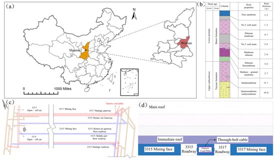
Figure 1.
Geographic location of the roof and floor in the Sangshuping Coal Mine; (c) location of the working face; (d) position relationship of working faces 3315 and 3317.
2.2. Roadway Deformation Characteristics
Analysis of rock mass deformation in adjacent roadways (Figure 2) via field investigations revealed that the 3.5 m-long adaptive helical bolts deployed in the 3317-return drift failed to provide adequate anchoring performance. This induced coal mass displacement toward the clearance zone, thereby compromising the effective control of coal rib deformation. Although conventional bolts did not suffer tensile fractures, their efficacy in restricting overall deformation remained limited. Furthermore, under the combined influence of residual dynamic pressure and hydraulic coal punching, plastic failure was initiated at the edges of the coal pillar, forming plastic softening zones. Subsequently, the failure zone gradually propagated inward, which further impaired the load-bearing capacity of the narrow coal pillar. These failure characteristics indicate that residual dynamic pressure, hydraulic coal punching, and suboptimal support schemes are the primary contributors to the insufficient load-bearing capacity of narrow coal pillars.
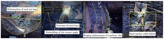
Figure 2.
Deformation of the surrounding rock in adjacent roadways.
3. Simulation Experiment
3.1. Determination of Similarity Ratio
The similarity simulation test was carried out based on the 3315-return drift of the Sangshuping Coal Mine. The dimensions of the narrow coal pillar in the 3315 working face were simulated as follows: height 3 m and width 5 m. The main structure of the test model frame was fabricated from 40 mm-thick acrylic panels. According to the actual size of the in situ coal pillar, the dimensions of the similarity model frame were determined, and the similarity ratios were established as follows:
- (1)
- Geometric similarity ratio
The height of the coal pillar in the similarity simulation was approximately 3 m, and the width was approximately 5 m; the usable simulation height and width of the test platform were 0.12 m and 0.20 m, respectively. The geometric similarity ratio is as follows:
In the formula, Ym and Yy represent the actual height and the model height, respectively, and Wm and Wy represent the actual and model widths, respectively.
- (2)
- Dynamic similarity ratio
Based on the materials used in the similarity simulation and the measured bulk density of the in situ coal, the bulk density similarity ratio is determined as the ratio of the model material bulk density (1.75 g/cm3) to the in situ coal bulk density (1.35 g/cm3), as follows:
In the formula, represent the bulk density of the i-th rock stratum in the model and in situ, respectively.
- (3)
- Motion similarity ratio
Kinematic similarity refers to the similarity that is based on geometric similarity, with the additional inclusion of time similarity. The kinematic similarity ratio for this simulation is determined as follows:
In the formula, denote the mining time of the in situ working face and the model working face, respectively.
- (4)
- Elastic modulus and stress similarity ratios
According to the calculation formulas of similarity theory, the similarity ratios of elastic modulus and stress are as follows:
In the formula, represent the similarity ratios of elastic modulus and stress, respectively.
3.2. Selection of Similar Materials
3.2.1. Coal Seam Similarity Material
As the primary component of the comprehensive examination, the analogous composition of the rock stratum exerts a pivotal impact on the test outcomes, thereby directly determining the success or failure of the examination. In previous studies, prefabricated blocks or plastic materials were employed as analogous materials. It is widely acknowledged that similar materials are blended with natural river sand, lime or gypsum, calcium carbonate, and other constituents in accordance with specified ratios, owing to their availability, low cost, and satisfactory simulation performance. In this study, natural river sand was selected as the aggregate, and calcium carbonate and gypsum were used as cementing materials to prepare similar materials for the coal and rock strata. Based on the measured physical and mechanical properties of the in situ coal and rock, corresponding mix codes for different lithologies were determined. Multiple standard cylindrical specimens (Φ50 mm × 100 mm) were then prepared with different mix proportions and water-to-binder ratios, and preliminary matching tests were conducted (Figure 3). Furthermore, a series of standard cylinders with different mix proportions was subjected to uniaxial compression tests. The final similar-material mix code “882” was selected because its mechanical parameters, after conversion using the stress similarity ratio of 1:32.5, showed the closest agreement with those of the prototype coal seam. The density of the selected similar material is approximately 1.75 g/cm3, corresponding to a bulk density similarity ratio of 1.3. In determining the mix proportions for different lithologies, the requirements of the similarity theorem for bulk density and compressive strength were strictly followed. The physical and mechanical parameters of the coal seam are listed in Table 1.
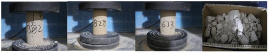
Figure 3.
Failure modes of similar materials.

Table 1.
Physical and mechanical parameters of the coal seam.
The dosage of the similarity materials for the coal pillar in the test was calculated by applying Equation (5) and incorporating the thickness parameter.
In the formula, the total weight of the I-layer material of the Gi model (kg), L is the model length (m), M is the model width (m), Hi is the bulk density of the first layer material (kN/m3), and g is the acceleration of gravity (m/s2).
The dosages of quartz fine sand, gypsum, and calcium carbonate were calculated based on Equation (5) and the material mix proportion number. The ratio of natural river sand to gypsum to calcium carbonate is expressed as a, b, (1 − b), and the quantity of each raw material is as follows:
The mix proportion number and the raw material dosages of the similar materials for the coal pillar were obtained via calculation, as presented in Table 2.
Table 2.
Mixture proportions of similar material for the No. 3 coal seam.
3.2.2. Support Structure Similarity Material
Based on the in situ support configuration and similarity-ratio calculations, and supported by physical and mechanical testing, 6 mm-diameter nylon threaded rods were selected as surrogate elements to model the support members. In the physical model, both the anchor cables and the anchor bolts were represented by the same nylon threaded rod; differences among schemes were mainly realized through the installation mode (bidirectional twin-pull versus one-side bolting), and the element length was scaled according to the geometric similarity ratio of 1:25. To represent the anchorage sections, nylon gaskets and nuts were installed at the rod ends to secure the components and to simulate the field pre-tightening effect. The corresponding specifications and parameters are summarized in Table 3.
Table 3.
Specifications and parameters of anchor cables and nylon rods.
3.3. Physical Simulation Experiment System
The experiment was conducted using a self-developed 3D test model frame by the research team. To ensure the visibility of the test process, the main body of the model frame was constructed from 40 mm-thick acrylic plates. The overall dimensions of the test platform are 260 mm × 280 mm × 200 mm, with an inner chamber size (height × width × thickness) of 200 mm × 200 mm × 120 mm. It mainly consists of rigid loading plates, flexible loading plates, coal pillars, and a base plate. The similarity simulation test system comprises a loading system and a monitoring system.
- (1)
- A servo-controlled compression testing machine (WDW-100M, Jinan Zhongluchang Testing Machine Manufacturing Co., Ltd., Jinan, China) was selected as the testing equipment for the experiment, which consists of a loading mechanism, a servo control system, and a data acquisition system. Owing to the height limitation of the test frame, the similar materials employed could not achieve the theoretically calculated similarity height. To ensure that the pressure was uniformly distributed over the upper part of the model, loading plates in contact with the model were introduced in the experiment. These loading plates were classified into two types: rigid and flexible. The flexible loading plates, made of rubber material, were in direct contact with the test model.
- (2)
- The entire experiment was monitored using a non-contact full-field strain measurement system based on the digital image correlation (DIC) technique [28], which is mainly composed of a CCD high-speed industrial camera, data recording software, and data analysis software. Prior to the experiment, it was necessary to apply a dense, randomly distributed speckle pattern on the surface of the test object to facilitate image tracking. During the experiment, the data recording software controlled the high-speed camera to continuously capture images at a preset frequency. After the experiment, the large volume of collected images was analyzed using VIC-2D (version 7) software to obtain the experimental data.
3.4. Test Scheme Design
In this experiment, the opposing tension anchor cable technology was adopted to reinforce narrow coal pillars. Considering the main influencing factors such as spacing, row spacing, number of anchor cables, and pre-tightening force, a variety of optimized support schemes were designed. The specifications and parameters are shown in Table 4.
Table 4.
Support schemes and factor settings for the test scheme design.
3.5. Model Test Procedure
- (1)
- Weigh the similarity simulation materials according to the designed dosages. After weighing, pour the materials into a mixing basin and add water for stirring. To maintain the integrity of the model, the interior of the mold shall be coated with a layer of solid grease before filling the model materials.
- (2)
- Attach strain gauges to the end and middle positions of the opposing tension anchor cables, respectively. Pre-design the hole positions for the models where the opposing tension anchor cables need to be arranged, and place the opposing tension anchor cables at the designated hole positions.
- (3)
- Pour the uniformly mixed similarity simulation materials into the mold by adopting the layered paving and compaction method until the mold is completely filled. Then, fill and compact the surface of the model to make it conform to the designed dimensions.
- (4)
- After the model fabrication is completed, leave it to stand for solidification to ensure model integrity. After air-drying for 72 h, the model can be detached from the mold base.
- (5)
- Upon the completion of model fabrication, arrange discrete speckles on the model surface using small black iron nails to facilitate the monitoring of model strain and displacement during the experiment via the digital image correlation (DIC) technique. Place the flexible loading plate and rigid loading plate on top of the test model.
- (6)
- Assemble the test model frame and place the test model on the test bench, ensuring that the loading system acts on the exact center of the model to avoid the eccentricity of external loads.
- (7)
- Set up the video recorder and CCD high-speed industrial camera to conduct full process monitoring of the deformation and displacement on both sides of the coal pillar during the experiment. Connect the strain gauges to the receiving equipment before starting the experiment.
- (8)
- Set the loading rate at 0.02 mm/min during the experiment. Based on the in situ virgin rock stress of 10.5 MPa, the load to be applied on the top of the model is calculated to be 12.9 kN. Continuously monitor the model throughout the experiment until the overall failure of the coal pillar occurs.
- (9)
- Replace the model and repeat the above steps for testing until the entire experiment is completed. The configuration of the analogous simulation test is illustrated in Figure 4.
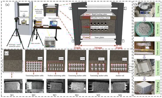 Figure 4. Overall arrangement of physical simulation experiments: (a) overall experimental setup diagram; (b) model fabrication process diagram; (c) arrangement of bidirectional tension anchor cables.
3.6. Test Results and Analysis
Based on previous research findings and field measurement data [29], it was found that when driving roadways along the edge of goafs, the stress concentration degree can reach 2.5 times the virgin rock stress due to the combined action of lateral abutment pressure and advanced abutment pressure. According to the in situ virgin rock stress of 10.5 MPa, the simulated virgin rock stress p was calculated to be 0.323 MPa. Overloading of 1.3p was adopted to simulate the stress concentration disturbance caused by the excavation of the 3317 haulage gateway; overloading of 1.7p to simulate the stress concentration disturbance caused by the mining of the 3317 working face; overloading of 2.0p to simulate the stress concentration effect on surrounding rocks caused by the excavation of the 3315 return gateway; and overloading of 2.5p to simulate the stress concentration disturbance on coal pillars caused by the mining of the 3315 working face. In the experiment, a stepwise loading method was adopted until the coal pillars completely lost their stability and failed.
3.6.1. Analysis on the Evolution Law of Horizontal Displacement of Coal Pillars
Figure 5 and Figure 6 illustrate the evolution law of horizontal displacement of coal pillar models under 6 different support schemes, where the color scale represents the horizontal displacement along the roadway direction. An analysis of the variation characteristics of horizontal displacement of coal pillar models under different support schemes reveals the following:
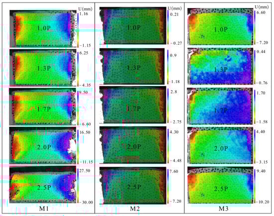
Figure 5.
Evolution patterns of horizontal displacement of coal pillars in M1, M2, and M3 models.
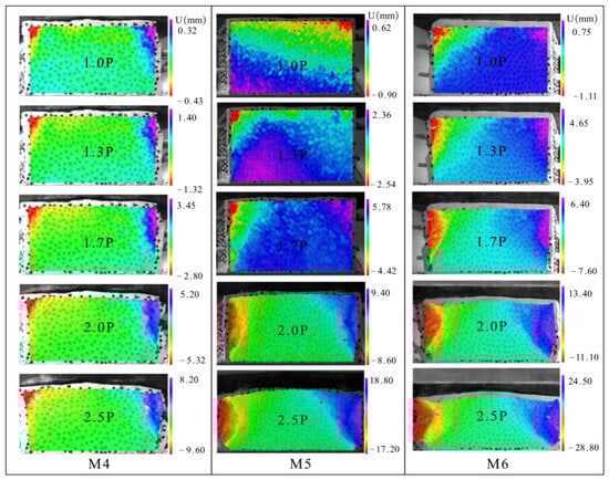
Figure 6.
Evolution patterns of horizontal displacement of coal pillars in M4, M5, and M6 models.
When the loading stress level reaches 1.0p, the overall displacement of coal pillars under all support schemes is relatively small, indicating that the support systems are in an elastic working state under the virgin rock stress condition.
When overloaded to 1.3p, the coal pillars under Schemes M1 and M6 initially exhibit compression-expansion deformation characteristics. In contrast, for the other support schemes adopting opposing tension anchor cables, the degree of compressive deformation of the models is relatively small due to the bilateral constraint effect of anchor cables, which verifies that opposing tension anchor cables have a significant constraint effect on the structural deformation of coal pillars.
When overloaded to 1.7p, the coal pillars under Schemes M1 and M6 undergo compressive deformation, with rib spalling occurring on the coal pillar ribs. As the mining-induced intensity increases, the deformation gradually intensifies, and the edge of the goaf experiences severe squeezing deformation towards the spaces on both sides. The maximum horizontal displacement appears at the ribs of the narrow coal pillars, reaching 9.5 mm and 7.6 mm, respectively. At this stage, the bolts in Scheme M6 do not exert an obvious effect on stabilizing the coal pillar ribs.
When overloaded to 2.0p, the horizontal displacement of coal pillars under all different support schemes increases to a certain extent. In particular, the coal pillars under Schemes M1 and M6 suffer severe deformation, which accelerates the overall instability and failure of the coal pillars. Compared with other support schemes using opposing tension anchor cables, the horizontal displacement of Scheme M5 increases rapidly, indicating that the small-spacing arrangement is more suitable for controlling the stability of narrow coal pillars under mining-induced disturbance.
When overloaded to 2.5p, the horizontal displacement of coal pillars under Schemes M1 and M6 increases sharply, with a large number of cracks appearing on the surface and subsequent fragmentation and spalling. At this point, the coal pillars have completely lost their load-bearing capacity. In comparison, the coal pillars under Schemes M2 and M4 only experience local surface damage while maintaining good integrity inside. This demonstrates that the small-spacing opposing tension anchor cable support can significantly enhance the deformation resistance and residual load-bearing capacity of narrow coal pillars under strong mining-induced conditions.
3.6.2. Analysis on the Development Law of Plastic Failure Zones in Coal Pillars
Figure 7 and Figure 8 illustrate the evolution law of plastic failure zones in coal pillar models under six different support schemes. Based on the full-field strain tensor inverted via DIC, the high-deformation zones and damage zones of coal pillars were identified for engineering applications using the Von Mises equivalent strain field [30,31]. High εv m values are concentrated in localized fractured or strain-localization regions and therefore serve as an indicator of damage severity, rather than representing a uniform strain level of the entire coal pillar.
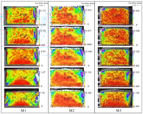
Figure 7.
Evolution patterns of plastic failure zones of coal pillars in M1, M2, and M3 models.
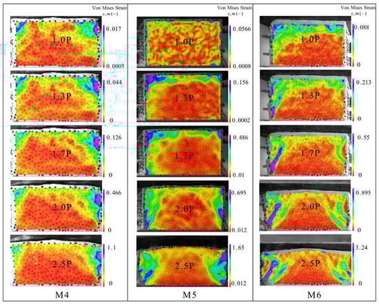
Figure 8.
Evolution patterns of plastic failure zones of coal pillars in M4, M5, and M6 models.
The analysis results are as follows:
When the load reached 1p, the increase in equivalent strain values was mainly concentrated in the obliquely upper part of the narrow coal pillars. After the applied load attained the virgin rock stress level, the equivalent strain values started to rise on the goaf side of the narrow coal pillars, and no significant plastic deformation was observed in any of the models.
When the load reached 1.3p, the equivalent strain values of coal pillars under Schemes M1 and M6 began to concentrate on the goaf side of the narrow coal pillars. This indicates that certain plastic failure zones had initially emerged on the goaf side of the narrow coal pillars, and as the disturbance intensity increased, the scope of these zones further expanded toward the interior of the narrow coal pillars. No significant plastic deformation occurred in the models under the other support schemes.
When overloaded to 1.7p, the equivalent strain values at the ribs of coal pillars under Schemes M1 and M6 increased significantly. Obvious plastic failure zones appeared at the ribs of narrow coal pillars at the initial stage of excavation, with the maximum failure locations occurring at the top and bottom corners of the coal pillar ribs. For the other support schemes, the degree of plastic failure at the coal pillar ribs further increased, but the failure zones tended to stabilize gradually after expanding to a certain extent. Although a certain degree of deformation occurred at both ribs of the coal pillars, no large-area plastic failure zones were formed.
When overloaded to 2.0p, the coal pillars under Schemes M1 and M6 basically lost their overall stability and developed large-scale plastic failure zones, indicating that their support systems were unable to maintain stability under high-stress conditions. In contrast, for the coal pillars supported by opposing tension anchor cables, only small-scale tension-shear failure occurred at the bottom corners of both ribs, and the failure zones gradually shifted toward the roadway centerline. This demonstrates that opposing tension anchor cables exert a distinct constraint and reinforcement effect on coal pillars.
When overloaded to 2.5p, the equivalent strain values of all parts of the coal pillars increased, and the area of plastic zones expanded accordingly. In particular, the plastic failure zone of the coal pillar under Scheme M5 expanded rapidly until the coal pillar failed and lost its load-bearing capacity. However, for the coal pillars under Schemes M2 and M4, plastic failure only occurred in small areas at the top and bottom corners of the ribs, while the interior of the coal pillars remained intact. This shows that the support system can significantly inhibit the propagation of plastic failure and effectively enhance the load-bearing capacity and stability of narrow coal pillars.
The above analysis reveals that the maximum load-bearing capacity of coal pillar models reinforced by opposing tension anchor cables is significantly higher than that of unreinforced models, and it is further improved with the increase in the number of opposing tension anchor cables. Opposing tension anchor cables can remarkably reduce the deformation level of the models before and after failure, especially when the anchor cable spacing is reduced; both the vertical and horizontal displacements of the models are effectively controlled. Under the action of the maximum external load, neither the double-row nor four-row small-spacing opposing tension anchor cable models suffered overall failure, indicating that such arrangement methods can significantly improve the load-bearing capacity and stability of narrow coal pillars.
3.7. Analysis of the Deformation Law of Test Specimens
Figure 9 shows the load-deformation curves of the test specimens. An analysis of these curves reveals the following: At the initial stage of loading, the axial load at each measuring point was relatively small, and the specimens were in the compaction stage. As the load increased, the anchor cables were subjected to compression and bending, causing the axial load to rise rapidly. At this stage, the deformation at the middle measuring points of the anchor cables was slightly higher than that at the end measuring points overall. With the gradual increase in external load, the deformation at the middle parts turned out to be lower than that at the ends until the specimens entered the failure stage.
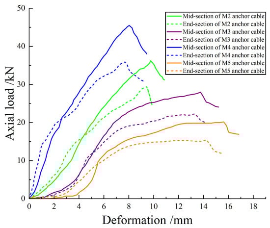
Figure 9.
Load-strain curve of bidirectional tension anchor cables.
An analysis of the loading behaviors of different test specimens reveals the following:
Specimen M5 featured a smaller number of anchor cable rows and larger spacing, resulting in a relatively weak overall constraint effect, and its peak load was significantly lower than that of the specimens with small-spacing opposing tension anchor cables. For Specimen M3, where no nuts or gaskets were installed at both ends, the constraint effect on the coal pillar was weak. At the initial stage of loading, the deformation increased rapidly with the rise in axial load, and the peak load was reached at approximately 26.4 kN, followed by immediate instability. Specimen M2 could stably withstand a load of about 0–10 kN at the initial loading stage, with the deformation increasing slowly as the load rose; after reaching the peak load of 35.6 kN, it rapidly lost its load-bearing capacity. In contrast, the deformation of Specimen M4 was consistently lower than that of other groups under the same load level. It failed rapidly after reaching the peak load of 44.2 kN, with a deformation of only 7.8 mm, which was 40.5% and 45.7% lower than that of Specimens M3 and M5, respectively. This fully demonstrates that the double-row small-spacing opposing tension anchor cables combined with end-locking devices can significantly enhance the axial load-bearing capacity of coal pillars.
In summary, the deformation of opposing tension anchor cables during loading is jointly controlled by external load and coal compaction, exhibiting stage-specific characteristics: the deformation at each measuring point is small at the initial loading stage; as the load increases, the deformation at the middle part is slightly larger than that at the ends; with the continuous increase in external load, the deformation at both ends gradually exceeds that at the middle part. Different arrangement forms show distinct differences in the constraint effect on coal pillars. Schemes M3 and M5 are associated with low peak loads and fast deformation development rates, making them unable to resist the extreme working conditions caused by the superposition of multiple mining activities; thus, their applicability is limited. Although Scheme M2 can improve the load-bearing capacity and stability of narrow coal pillars to a certain extent, the dense arrangement of anchor cables leads to substantially higher material consumption and installation demand, resulting in poor economy and failing to meet engineering cost-control requirements. The material consumption and material cost per meter of roadway for each scheme are shown in Table 5.
Table 5.
Material consumption and material-only cost per meter of roadway.
From a cost–benefit perspective, a per-meter roadway comparison indicates that M2 requires approximately twice the reinforcement density and material input of M4, while the performance gain is not proportional. In contrast, Scheme M4 achieves the lowest deformation and the highest peak load under the same loading level, indicating superior deformation control and load-bearing improvement under the test conditions at a moderate material cost. Therefore, considering both mechanical performance and cost-effectiveness, Scheme M4 provides the most balanced solution for field implementation. Based on this multi-dimensional evaluation—including economy and adaptability to on-site application scenarios—Scheme M4 is finally determined as the optimal opposing tension anchor cable arrangement scheme for on-site construction.
4. Field Industrial Test
4.1. Subsection
The length of the opposing tension anchor cables exceeded the reserved width of the coal pillars by 1.5 m, and flame-retardant and anti-static cable protection sleeves with a certain wall thickness were pre-embedded at the ends of the anchor cables. This facilitated the installation of locking devices after removing the sleeves during the excavation of the 3317 haulage gateway, thus achieving one-time tension forming. Meanwhile, high-strength extruded threaded collars were installed at preset intervals along the length direction of the anchor cables to enhance the interfacial friction with the grouting anchoring material, thereby effectively restraining the internal deformation of the coal pillars. After the fabrication of the new-type opposing tension anchor cables (Figure 10), tension tests were conducted synchronously with conventional anchor cables. The results showed that their initial anchoring force reached more than three times that of conventional anchor cables, and they could stably provide an anchoring force of not less than 350 kN.
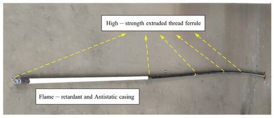
Figure 10.
Structure of bidirectional tension anchor cable.
4.2. Construction Process Flow
According to the production plan of the coal mine, the excavation of the 3315 return gateway must be completed before the mining of the 3317 working face. To ensure the support effect, an innovative step-by-step construction technology was adopted in the test, whose core lies in realizing “two-stage tensioning and collaborative locking” before and after the breakthrough of adjacent roadways. The enhanced section support scheme is shown in Figure 11.
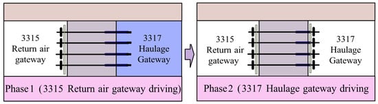
Figure 11.
Support design diagram for the reinforced cross-section.
In the first stage, horizontal boreholes with a designed length of 6 m were drilled on the coal pillar rib at the side of the 3315 return gateway. The prefabricated 6.5 m-long anchor cables with grouting pipes and slurry stoppers were inserted into the boreholes, with the ends of the anchor cables reserved for the space to be penetrated by the 3317 haulage gateway. Full-hole grouting was then performed; after the grout was initially set, the primary tensioning of the anchor cables at the side of the 3315 return gateway was carried out, followed by the installation of bearing plates and locking devices. In the second stage, when the excavation of the 3317 haulage gateway advanced to the position of the reserved ends of the anchor cables, the exposed cable ends were cut to the designed length. Bearing plates and locking devices were installed at the side of the 3317 haulage gateway. Tensioning equipment was used to conduct the secondary tensioning of the anchor cables, thereby achieving the final bidirectional opposing tension locking of the coal pillars.
4.3. On-Site Monitoring Scheme and Result Analysis
Surface Displacement Monitoring of Roadway Surrounding Rock
A cross-point layout method was adopted to arrange one set of convergence observation points for the two ribs and one set of roof subsidence observation points at each cross-section. Drill holes were made at the monitoring positions using a pneumatic drill, followed by spray painting to mark the observation points.
Starting at 25 m away from the construction opening, a monitoring point was set every 50 m, resulting in a total of six monitoring stations at positions of 25 m, 50 m, 100 m, 150 m, 200 m, and 250 m. These stations were numbered 1# to 6# in the order from the closest to the farthest relative to the construction opening. Observations were conducted, and data were recorded every 3 days. The obtained convergence values of the two roadway ribs, roof subsidence values, roof separation displacement, and anchor cable stress are shown in Figure 12.
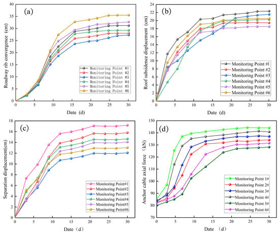
Figure 12.
On-site monitoring diagram. (a) Monitoring curve of roadway sides convergence; (b) monitoring curve of roadway roof settlement; (c) monitoring curve of roof separation in roadway; (d) monitoring curve of axial force in anchor cables.
During the 30-day deformation monitoring period, the roadway deformation gradually stabilized. The maximum convergence value of the two roadway ribs reached 37.3 cm, and the maximum roof subsidence was 21.6 cm. The monitoring results clearly indicated that the reinforced roadway exhibited excellent stability and deformation control performance, which improved the stability and safety of the project.
The roof separation displacement was extremely small, with the maximum value of 17.3 cm recorded at Monitoring Point 1. The variation trend of separation displacement showed a rapid increase at the initial stage, followed by a gradual stabilization. Compared with the original support scheme, the roof separation displacement was effectively controlled. This avoided the reduction in the effective roof-to-floor height caused by the formation of a net-shaped structure due to roof subsidence, thus ensuring the normal service of the roadway.
The maximum axial force of the anchor cables installed on the coal pillar ribs was approximately 145 kN, which was far below their ultimate breaking load. The analysis showed that the difference between the initial axial force and the designed preload was minimal, indicating that the construction quality of the opposing tension anchor cables met the design expectations and the anchoring effect was reliable. At the initial stage of roadway excavation, the axial force of the anchor cables rose rapidly, which demonstrated that the anchor cables had quickly entered the working state, effectively exerted the active support function, and significantly enhanced the surrounding rock control effect. This verified the necessity of reinforcing the narrow coal pillar ribs with opposing tension anchor cables.
After the completion of the airtight project for the 3315 return gateway, and following the completion of mining in the 3317 working face along with a comprehensive evaluation, the subsequent work of the 3315 return gateway was restarted, as shown in Figure 13.
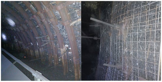
Figure 13.
The real picture of the 3315 return roadway after closed opening.
After the airtight wall was opened, a second round of monitoring was conducted at the original monitoring points for 30 days. The monitoring results indicated that the maximum convergence of the two coal pillar ribs was 89 cm, the maximum roof subsidence was 56 cm, and the maximum roof separation displacement was 55 cm—all significantly below the limits specified in the technical requirements. In addition, the maximum axial force of the anchor cables on the coal pillar ribs reached 325 kN; however, no obvious deformation was observed on the roadway ribs, and the opposing tension anchor cables arranged on the side adjacent to the coal pillar did not break or pull out throughout the monitoring period. A comparison of the monitoring data between the excavation period and the mining period showed that the axial force of the anchor cables increased from 145 kN to 325 kN, while the convergence of the two ribs increased from 37.3 cm to 89 cm during the same period. This demonstrates that the bidirectional opposing-tension anchor cables can continuously provide binding force in response to surrounding rock deformation, effectively exert the “collaborative locking” effect, and prevent the instability and failure of the coal pillar ribs caused by stress concentration.
5. Discussion
The present discussion is based on the gob-side roadway narrow coal pillar reserved for the 3315 working face in the Sangshuping Coal Mine. Using similarity theory, we developed a physical simulation system for narrow coal pillars reinforced by bidirectional opposing-tension anchor cables and conducted multi-condition staged-loading tests to examine the bearing behavior and failure characteristics of the pillar. Together with field-scale industrial verification, this work proposes a process-level GA support technology. The following discussion interprets these findings in relation to previous studies, engineering practice, and the limitations of the present work to provide a comprehensive understanding of the results.
However, this study has several limitations that should be addressed in future work. First, the comparative evaluation of the support schemes is still limited in quantitative evidence; future work will adopt a more structured test design with repeat experiments and refined quantitative indicators to strengthen statistical confidence. Second, the recommendation of Scheme M4 is constrained by the specific geological and mining conditions considered in this case; further validation under different stress levels, pillar widths, roof/floor lithologies, and tectonic disturbance conditions will be carried out through additional cases and targeted verification. Third, due to roadway closure after support installation, field monitoring was performed only during two 30-day periods; when opportunities arise, long-term continuous monitoring will be implemented to better capture time-dependent deformation evolution and to further demonstrate the sustained effect of collaborative locking over time.
In summary, the present findings provide a practical basis for narrow coal pillar support at the Sangshuping Coal Mine and offer a scientific reference for parameter optimization and process design of reinforcement technologies for narrow coal pillars in gob-side roadways. The proposed approach also provides useful engineering guidance for reinforcing narrow coal pillars under similar complex working conditions.
6. Conclusions
- (1)
- Aiming at the core problems of the 3315 return gateway, including the weak and fractured immediate roof, the susceptibility of coal pillars to plastic degradation, and the inability of the original support to effectively constrain the coal mass, an innovative GA support technology was proposed from a technical perspective. By implementing “two-stage tensioning and collaborative locking” before and after the breakthrough of adjacent roadways, the problem of coordinated construction during asynchronous operations was solved. Meanwhile, it enhanced the bearing capacity of coal pillars and improved roadway stability.
- (2)
- Taking the 3315 return gateway as the engineering background, a similarity simulation test system for narrow coal pillar reinforcement with opposing tension anchor cables was established based on the similarity principle. Six groups of comparative tests yielded the following results: neither the double-row nor the four-row opposing tension anchor cable models with small spacing suffered overall failure; only local plastic failure occurred at the roof and floor corners of the ribs, while the internal structure of the coal pillars remained intact. In the failure stage, the deformation of the double-row opposing tension anchor cables with small spacing was reduced by 40.5% and 45.7%, respectively, compared with the large-spacing layout and the non-preloaded layout. Considering the requirements for improving coal pillar stability and economic benefits, the double-row dense layout scheme of opposing tension anchor cables is more reasonable, which provides practical reference for the selection of engineering support schemes.
- (3)
- The narrow coal pillars of the 3315 working face were reinforced by adopting the new GA support technology, and the enhanced support system significantly improved the stability of the roadway. Field monitoring data showed that during the excavation period, the maximum convergence of the two roadway ribs was 37.3 cm, the maximum roof subsidence was 21.6 cm, and the maximum roof separation displacement was 17.3 cm—representing a significant reduction in surrounding rock deformation compared with the original support scheme. The results of the second monitoring after mining disturbance indicated that the maximum convergence of the two ribs was 89 cm, the maximum roof subsidence was 56 cm, the maximum roof separation displacement was 55 cm, and the maximum axial force of the anchor cables was 325 kN, accounting for only 59% of the ultimate breaking load (550 kN). All indicators were significantly superior to those of the conventional support scheme, which fully verified the engineering applicability and reliability of this support technology.
Author Contributions
Conceptualization, A.L.; methodology, A.L.; software, S.T. and L.F.; validation, S.T. and L.F.; formal analysis, S.T.; investigation, S.T.; resources, L.F.; data curation, N.Y.; writing—original draft preparation, S.T.; writing—review and editing, S.T.; visualization, N.Y.; supervision, N.Y. and H.L.; project administration, A.L.; funding acquisition, A.L. All authors have read and agreed to the published version of the manuscript.
Funding
This research received no external funding.
Institutional Review Board Statement
Not applicable.
Informed Consent Statement
Not applicable.
Data Availability Statement
The original contributions presented in this study are included in the article. Further inquiries can be directed to the corresponding author.
Acknowledgments
The authors are very grateful to the reviewers for carefully reading the manuscript and providing valuable suggestions.
Conflicts of Interest
The authors declare no conflicts of interest.
References
- Lu, S.; Sun, M.; Niu, S.; Zhang, Y. Variation Characteristics of Support Strength and Stability in Post-Peak Large Deformation for Roadways Surrounding Rock. Sci. Rep. 2025, 15, 41642. [Google Scholar] [CrossRef]
- Dou, Z.; Xu, S.; Han, R. Study on the Influence of Overlying Coal Seam Mining on the Deformation of Floor Roadway Surrounding Rock. Sci. Rep. 2025, 15, 38416. [Google Scholar] [CrossRef] [PubMed]
- Shan, P.; Zhang, L.; Yan, C.; Xu, H.; Meng, Z.; Xi, B.; Xu, G. Monitoring and Prediction of Deformation and Failure of Roadway Surrounding Rock Based on Binocular Vision and Random Forest. Appl. Sci. 2025, 15, 12070. [Google Scholar] [CrossRef]
- Jin, J.; Wang, Y.; Jin, X.; Qiao, F. Reasonable Width of Deteriorated Coal Pillars and Surrounding Rock Control for Roadways in Thick Coal Seams: A Case Study of Datong Coal Mine Area, China. Appl. Sci. 2025, 15, 10110. [Google Scholar] [CrossRef]
- Xu, S.; Qu, F.; Li, Y.; Wang, Y.; Ji, Y. Surrounding Rock Deformation Control of Ore-Drawing Roadway Under Cyclic Ore-Drawing Disturbance. Appl. Sci. 2025, 15, 9804. [Google Scholar] [CrossRef]
- Zhang, T.; Xu, Y.; Wei, C.; Su, H.; Feng, Y.; Yu, L. The Influence of Disturbance Location and Intensity on the Deformation and Failure of Deep Roadway Surrounding Rocks. Front. Mater. 2025, 12, 1550247. [Google Scholar] [CrossRef]
- Xue, Y. Optimization of Small Coal Pillar Width and Control Measures in Gob-Side Entry Excavation of Thick Coal Seams. Sci. Rep. 2024, 14, 23304. [Google Scholar] [CrossRef]
- Ma, X.; Zhai, Z.; Xiang, J.; Wei, M.; Tian, Z.; Chen, L. Research on Deformation and Failure Mechanism of Surrounding Rock in Inclined Strata with Soft–Hard Interbedded Roadways. Rock Mech. Rock Eng. 2024, 57, 11319–11332. [Google Scholar] [CrossRef]
- Wang, H.; Liu, Y.; Li, L.; Yue, G.; Jia, L. Study on Critical Width of Semi-Coal Rock Roadway of Shallow-Buried Thin Coal Seam Based on Coal Side Self-Stabilization. Sustainability 2024, 16, 5689. [Google Scholar] [CrossRef]
- Zhang, X.; Wang, F.; Qu, H.; Liu, C.; Li, Z.; Hao, W. Surrounding Rocks Deformation Mechanism and Roof Cutting-Grouting Joint Control Technology for Soft and Thick Coal Seam Roadway. Sustainability 2023, 15, 15415. [Google Scholar] [CrossRef]
- Li, A.; Lu, L.; Zhou, Y. Study on the Mechanism and Application of Support Reinforcement for Narrow Coal Pillars under High-Pressure Disturbances in Deep Mining. J. China Univ. Min. Technol. 2025, 54, 355–371. [Google Scholar]
- He, F.; Tao, K.; Wang, D.; Zhang, J.; Wu, Y. Mechanism and Control of Asymmetric Deformation of Surrounding Rock in Gob-side Roadway Driving along Narrow Coal Pillar in Extra-Thick Coal Seam. Results Eng. 2025, 28, 108042. [Google Scholar] [CrossRef]
- Gu, W.; Zhang, H.; Han, Z.; Tang, H.; Pei, J.; Wu, S.; Xu, D. Research on the Bearing Characteristics of Narrow Coal Pillars in Double-Roadway Excavation Under the Influence of Full Dynamic Pressure. Appl. Sci. 2025, 15, 7148. [Google Scholar] [CrossRef]
- Yang, H.; Han, C.; Zhang, N.; Wang, J.; Chen, Q.; Liu, J.; He, S. Transferring Pressure Mechanism Across Gob-Side Roadway Goaf with Coal Pillar During Distant Face Mining: A Case Study. Appl. Sci. 2025, 15, 4274. [Google Scholar] [CrossRef]
- Wu, X.; Guo, L.; Sun, Y.; Wu, X.; Zhang, N. Research on the Law of Multiple Mining in Close Coal Seams and the Roadway Support of Lower Coal Seam. Sci. Rep. 2025, 15, 37518. [Google Scholar] [CrossRef] [PubMed]
- Wang, Y.; Xie, S.; Wu, Y.; Liu, C.; Wang, Z. Optimized Positioning and Cross-Layer Control for Roadways beneath Residual Coal Pillars in Extremely Close-Distance Coal Seams. J. Mt. Sci. 2025, 22, 3850–3868. [Google Scholar] [CrossRef]
- Wang, R.; Shi, Z.; Fan, J.; Wang, Y.; Peng, Y.; He, M.; Zhang, B. Research on Narrow Coal Pillar Width Optimization and Surround Rock Control in Shiquan Mine. Rock Mech. Bull. 2025, 4, 100172. [Google Scholar] [CrossRef]
- Guo, S.; Hu, S.; Huang, J.; Gao, Z.; Cheng, Y.; Han, J.; Yang, L. Stability Control Technology for Surrounding Rocks in Gob-Side Entry Driving with Small Coal Pillars under Dynamic Pressure. Energies 2023, 16, 7887. [Google Scholar] [CrossRef]
- Shan, R.; Peng, Y.; Zhang, W. Deformation and Failure Mechanism of Two Sides of Bottom-Driven Roadway in Deep Thick Coal Seam. J. Min. Saf. Eng. 2023, 40, 730–742. [Google Scholar] [CrossRef]
- Wang, F.; Jiang, Z.; Liu, C. Surrounding Rock Movement Mechanism and Cable Reinforcement Support Technology for Gob-Side Entry Retaining in the Dynamic Pressure Area of Deep Fully-Mechanized Mining Face. J. Min. Saf. Eng. 2024, 41, 1103–1115. [Google Scholar] [CrossRef]
- Guo, D.; Zhang, W.; Li, X. Comprehensive Pressure Relief Technology of Small Coal-Pillar Roadway Protection in Double-Roadway Excavation and Its Application. J. Min. Saf. Eng. 2025, 42, 556–566. [Google Scholar] [CrossRef]
- Peng, L.; Xu, S.; He, M. Numerical Simulation Study on Through-Anchor Cable Reinforcement Control of Inter-Roadway Coal Pillars in Double-Roadway Layouts. Sustainability 2025, 17, 2416. [Google Scholar] [CrossRef]
- Gu, C.; Wang, B.; Wang, J. Research on bidirectional-reinforcement mechanism of narrow coal pillar of gob-side entry driving based on inflatable lock-type anchor. Coal Sci. Technol. 2022, 50, 106–116. [Google Scholar]
- Wang, J.; LV, S.; Yang, G. Bidirectional Reinforcement of Narrow Pillar with Inflatable Lock-Type Anchor Experimental Investigation and Its Application. J. Min. Sci. 2024, 9, 258–269. [Google Scholar] [CrossRef]
- Chen, Z.; Ren, S.; An, D.; Zhang, P. Mechanical Behavior of Rigid Support and Flexible Support in Response to Large Deformation Disaster in Tunnel. Int. J. Civ. Eng. 2025, 23, 1597–1614. [Google Scholar] [CrossRef]
- Ma, C.; Wang, P.; Li, J.; Fan, X.; Dong, Z.; Chen, Z.; Wang, X. Support Patterns of Roadways Under Fractured Surrounding Rocks Based on the Quality Level of Rock Mass. Appl. Sci. 2024, 14, 10598. [Google Scholar] [CrossRef]
- Guo, L.; Tao, Z.; He, M.; Coli, M. Excavation Compensation and Bolt Support for a Deep Mine Drift. J. Rock Mech. Geotech. Eng. 2024, 16, 3206–3220. [Google Scholar] [CrossRef]
- Li, A.; Ji, B.; Ma, Q.; Ji, Y.; Mu, Q.; Zhang, W.; Mu, P.; Li, L.; Zhao, C. Physical Simulation Study on Grouting Water Plugging of Flexible Isolation Layer in Coal Seam Mining. Sci. Rep. 2022, 12, 875. [Google Scholar] [CrossRef] [PubMed]
- Peng, W.; Zhang, Y.; Feng, S. Secondary Development and Application of Roadway-Bearing Model Based on Residual Strength of Deep Fractured Rock. Adv. Civ. Eng. 2025, 2025, 4964214. [Google Scholar] [CrossRef]
- Kong, X.; Qin, Z.; Xiao, Y.; Shan, R.; Zhu, H.; Dai, Y. Distribution Characteristics and Control Strategies for Plastic Zones Around Coal Mining Roadways Under Various Support Methods and Geological Conditions. Min. Metall. Explor. 2025, in press. [Google Scholar] [CrossRef]
- Tang, Q.; Ding, Z.; Zhang, J.; Jia, J.; Di, G. Evolution and Control of Plastic Zone of Roadway Surrounding Rock Under the Influence of Mining. Min. Metall. Explor. 2025, in press. [Google Scholar] [CrossRef]


Disclaimer/Publisher’s Note: The statements, opinions and data contained in all publications are solely those of the individual author(s) and contributor(s) and not of MDPI and/or the editor(s). MDPI and/or the editor(s) disclaim responsibility for any injury to people or property resulting from any ideas, methods, instructions or products referred to in the content. |
© 2026 by the authors. Licensee MDPI, Basel, Switzerland. This article is an open access article distributed under the terms and conditions of the Creative Commons Attribution (CC BY) license.