Abstract
Practical testing of a novel underwater circulating towing experimental system has revealed that vibrations induce unstable vehicle operation, necessitating the implementation of vibration mitigation strategies. This paper first establishes a dynamic model of the system using mechanical system dynamics theory and analyzes its vibrational characteristics. The analysis shows that the third-order natural frequency closely aligns with the rotational frequency of the traction motor, thereby risking resonance and performance instability. To address this, shock absorbers are incorporated, and the spring stiffness of the tensioning device is adjusted. Using the vehicle’s vibration acceleration root mean square as the objective function, an annealed particle swarm optimization algorithm is employed to optimize parameters including the equivalent stiffness and damping coefficients of the shock absorbers, as well as those of the spring tensioning device, thus refining the vibration mitigation strategy. The results demonstrate a 6% increase in the initial third-order natural frequency, effectively avoiding resonance. Additionally, the average vibration displacement and acceleration are reduced by 45.8% and 20%, respectively, significantly enhancing operational stability. This research provides substantial theoretical support for improving system stability.
1. Introduction
Underwater vehicles are essential for advancing modern marine science and technology, playing a vital role in driving the marine economy, ensuring national security, and promoting environmental protection [1,2]. To reduce the high costs associated with at-sea trials, underwater towing experimental platforms have been developed as a cost-effective alternative. These platforms streamline operations, simulate realistic marine environments, and minimize maintenance expenses, thereby enabling efficient assessment of vehicle performance. However, the tight coupling among the towing system’s components means that any anomalies can be transmitted directly to the underwater vehicle, potentially leading to significant misinterpretations of its performance. Consequently, the development of stable and reliable towing systems is critical for the successful advancement of underwater vehicles, underscoring the practical significance of this research [3].
Significant progress has been made in recent years in developing and applying underwater towed experimental platforms. For instance, Tian et al. developed a low-noise trimaran-shaped platform for towed array flow noise measurements, demonstrating excellent wake field characteristics and low noise levels through the finite volume method and Lighthill’s acoustic analogy [4]. Oladele, Omotayo et al. adopted the finite element method based on the lumped mass-spring-damper approach to simulate the dynamics of an autonomous underwater vehicle (AUV) that towed another identically sized AUV via a submarine cable, and they employed unsteady-state operations to evaluate the stability and performance of the established model [5]. Based on similarity principles, Yang et al. designed a small-scale dynamic prototype and conducted laboratory experiments on towed body trajectories, providing new methods for array positioning technology [6]. Park Jong-Yeol, Lee Shin-Hyung et al. utilized a towing tank and employed an inertial measurement unit (IMU) to measure the attitude of the towed object, demonstrating that a low center-of-gravity design can effectively improve pitch motion stability and suppress motion fluctuations when the geometric parameters and traction points of the towed object are fixed [7]. The design of winch systems was investigated by Tian et al. [8], while Schuch et al. developed a two-stage towing system and evaluated its controller under various conditions [9]. Wu et al. proposed a controllable towing model capable of flexible multi-degree-of-freedom motion [10]. For miniaturized applications, Pallayil et al. developed a lightweight digital thin-line towed array (DTLTA) [11]. Furthermore, Sakai et al. applied an autonomous towing system to a waterway project, validating the model’s stability and manufacturing a prototype [12].
Despite these advancements, most existing towing systems are open-loop, which, while functional, often lack precision. To overcome these limitations, this paper proposes a novel underwater recirculating towing system. This innovative platform is specifically designed to study the behavior and performance of underwater vehicle models. Unlike conventional systems, it operates as a closed-loop circulation system equipped with a depth adjustment mechanism, enabling the towing of ship models at different depths and along various trajectories within a stationary pool. This provides a valuable platform for simulating underwater vehicle motion in marine environments. However, physical testing revealed significant vibrations that not only adversely affect the test vehicle’s performance but may also compromise the system’s long-term durability. To address these issues, this paper investigates and proposes mitigation strategies. Our approach integrates the installation of vibration dampers, optimization of the tensioning device’s spring stiffness, and application of the Simulated Annealing Particle Swarm Optimization (SA-PSO) algorithm. Collectively, these measures aim to suppress vibrations and enhance the overall stability and reliability of the system.
2. The Composition and Dynamic Modeling of Underwater Towing Systems
2.1. System Dynamics Modeling
The configuration of the underwater cyclic towing system, an experimental platform for studying underwater vehicle motion, is depicted in Figure 1. To analyze its operational characteristics, a corresponding dynamic model must be established. As the system represents a multi-body dynamics problem, its structure requires simplification by retaining key components such as the traction mechanism, guide pulleys, rope loop, navigational body, and tensioning device. Owing to its cyclic operation, the system’s transmission method and structural design differ significantly from traditional underwater towing models, rendering conventional modeling approaches unsuitable. Therefore, this study adopts the dynamic modeling approach of a tow-type elevator with a 1:1 rope ratio to construct the system model. Through simplification and analysis of the structure in Figure 1, the dynamic model of the underwater cyclic towing system, presented in Figure 2, is derived.
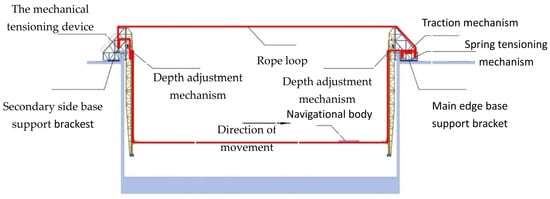
Figure 1.
Schematic of the underwater towing system.
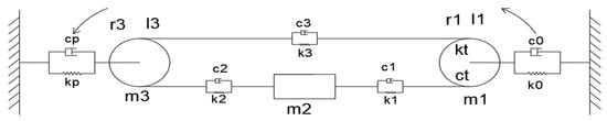
Figure 2.
Dynamic Model of the Underwater Cyclic Towing System.
- —Equivalent stiffness and damping of the spring tensioning device.
- —Equivalent mass of the main-side base structure, equivalent radius, and equivalent moment of inertia of the traction wheel.
- —Equivalent stiffness and damping of the ropes on both sides of the vehicle.
- —Equivalent mass of the underwater vehicle.
- —Equivalent mass of the auxiliary-side base structure, equivalent radius, and equivalent moment of inertia of the tensioning wheel.
- —Equivalent stiffness and damping of the mechanical tensioning device.
- —Equivalent stiffness and damping of the rope connecting the auxiliary-side and main-side base structures.
The equation of motion is formulated using Lagrangian mechanics [13], taking rightward as the positive direction.
In the equation above:
T—the total kinetic energy of the system.
D—the Rayleigh dissipation function.
U—the total potential energy of the system.
—denotes the generalized coordinates.
—denotes the generalized velocity.
where and denote the angular displacements of the traction sheave and guide pulley, and and represent their angular velocities.
By substituting Equations (2)–(4) into Equation (1) and simplifying the resulting expression, we obtain the following equation:
Here, denotes the system mass matrix, the damping matrix, the stiffness matrix, and the external instantaneous excitation force matrix. The vectors , , and represent the system’s acceleration, velocity, and displacement, respectively.
2.2. Dynamic Model Parameters of the Underwater Towing System
2.2.1. System Stiffness Parameters
A linear elastic model is applicable for calculating the rope stiffness, as the rope operates within its elastic deformation range under the system’s loading conditions. Given that the acting force is within the material’s allowable limits, the stiffness is determined using the principles of material mechanics [14].
where
- E—elastic modulus of the rope
- A—cross-sectional area of the rope
- L(t)—length of the rope segment
As per [15], the system exhibits time-varying behavior because the lengths of the two lower ropes, and consequently their mass and stiffness, change continuously during operation. This implies that the stiffness coefficients and are time-dependent functions. The non-rigid transmission from the servo motor to the traction wheel is accounted for by an equivalent torsional stiffness = [16]. In contrast, the mechanical tensioning device is static during motion, having been pre-configured before startup, leading to the assignment of . In addition, this study was conducted in an indoor constant-temperature environment; thus, the influence of temperature on the ropes is minimal and can be neglected.
2.2.2. Analysis of System Damping Parameters
In this system, without considering the aquatic environment, certain inherent components possess damping characteristics that influence the system’s vibrational response. However, as directly measuring damping in practical mechanical systems is challenging, the proportional viscous damping method was adopted for equivalent modeling to obtain the equivalent damping parameters, as defined by:
In the equation, and represent the Rayleigh damping coefficients. Given that this drag system operates in a still water environment and its transmission mechanism is dry-sealed, mechanical damping accounts for a large proportion and thus constitutes a key component of the system damping. Furthermore, both this drag system and the traction elevator are rigid-flexible-coupled closed-loop systems, and their transmission modes, structural configurations, and vibration generation mechanisms are analogous. Therefore, research findings in the field of elevator dynamics provide a reference for the present study, and α is thus set to 0.01 herein.
Regarding the value of , the relevant literature [17] reports its range to be 0.006–0.027. To determine an appropriate value for , four values (0.006, 0.01, 0.015, and 0.02) within this range were selected to conduct a parameter sensitivity analysis of β. The analysis procedure was implemented as follows: first, different values of β were substituted into Equation (7) to derive the corresponding damping matrices ; second, each damping matrix was substituted into Equation (5) to calculate the average vibration acceleration for each β value; finally, the sensitivity coefficient was computed using the formula (where denotes the sensitivity coefficient, the percentage change in the average vibration acceleration, the percentage change in β, and a system is deemed insensitive to a parameter variation when ). The results show that, taking β = 0.01 as the reference, the sensitivity coefficients corresponding to all the selected β values within the aforementioned range all satisfy . This indicates that the system response is not significantly sensitive to variations in β within 0.006–0.027. Based on this finding, the present study adopts β = 0.01 as the fixed parameter for all subsequent calculations.
2.2.3. Description of the External Excitation Force in the System
To investigate the motion states of the system during operation, a linear velocity measuring wheel was installed at the traction cable’s towing end. The linear velocity and accumulated circumference of the wheel’s outer circle were calculated from the wheel’s rotational speed and circumference, enabling real-time and accurate measurement of the model’s towing velocity and displacement. These data were then subjected to cubic interpolation for refinement. Following this, these data were differentiated to obtain the vehicle’s displacement and acceleration curves at a depth of 2 m for speeds of 1 m/s, 2 m/s, and 3 m/s, as shown in Figure 3.
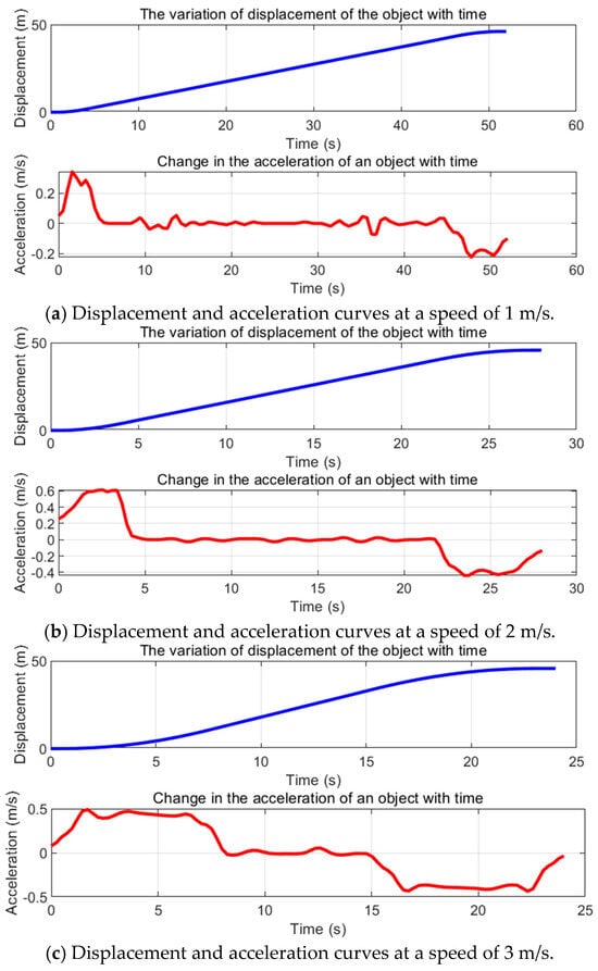
Figure 3.
Displacement and acceleration curves of the vehicle at various speeds.
The dynamic variation in an object’s velocity in water causes continuous changes in hydrodynamic drag, rendering direct calculation of the instantaneous excitation force impractical. We therefore derived this force indirectly from the pre-obtained acceleration profile. Due to the strong coupling within the system, the vehicle’s instantaneous acceleration is taken as equivalent to the system’s overall acceleration. Thus, we calculate the external instantaneous excitation force during operation based on inter-component interactions, as follows [18].
3. Analysis of the Vibration Characteristics of Underwater Towing Systems
A numerical strategy based on the instantaneous structural assumption is employed. The system dynamics are discretized, and the equations of motion over the interval [t, t + Δt] are modeled as constant-coefficient differential equations. This piecewise-linear approximation enables the solution of the system’s continuously varying dynamic characteristics. In this study, SolidWorks (2024), ANSYS (2022r1), and MATLAB (2023a) are utilized to accomplish the research work, with the corresponding flowchart presented as follows:

3.1. Theoretical Methodology
3.1.1. Modal Analysis
Modal analysis is a computational technique for determining the vibration characteristics of structures or mechanical systems [19]. It aims to identify the system’s modal parameters, which are crucial for validating the design. The fundamental equation is:
As damping solely influences the dynamic response of the system and not its natural frequencies, it can therefore be disregarded in this context as follows:
The characteristic equation is given by:
Here, is the system’s natural frequency. Defining yields:
Equation (12) represents an eigenvalue problem for matrices and . We compute the eigenvalues in MATLAB, thereby determining the system’s natural frequencies.
3.1.2. Added Mass Effect
According to potential flow theory [20], the added mass for an object accelerating in a given direction can be expressed as:
Here, is the fluid density and is the velocity potential. For a body in an unbounded fluid, where the disturbance kinetic energy is finite and the boundary is at infinity, the surface integral is zero; it follows that the kinetic energy reduces to:
Assuming a unit velocity of V = 1, the velocity potential can be expressed as . Substituting this into the kinetic energy equation yields Q. Therefore, the added mass for an object moving in an ideal fluid is given by:
Since the velocity potential represents the distribution of the velocity field in the fluid and is a scalar function, the added mass experienced by an object moving in an ideal fluid depends solely on the shape and direction of the object’s motion, independent of its velocity or acceleration.
In this system, the submerged portion primarily comprises the ropes and the vehicle. Since the linear density of the adopted rope is 0.087 kg/m, its mass is much smaller than that of the system. Therefore, the influence of the rope on the system is neglected herein, and only the added water mass of the underwater vehicle is discussed. Owing to the vehicle’s guidance mechanism (shown in Figure 4), its motion is constrained to a single direction during operation. Furthermore, this study considers only the vehicle’s motion in the towing direction. Consequently, the vehicle’s dynamics can be treated as a single-degree-of-freedom system. Based on established methods for calculating added mass in ship and marine engineering [21], the added mass for the vehicle undergoing longitudinal unsteady motion is given by:
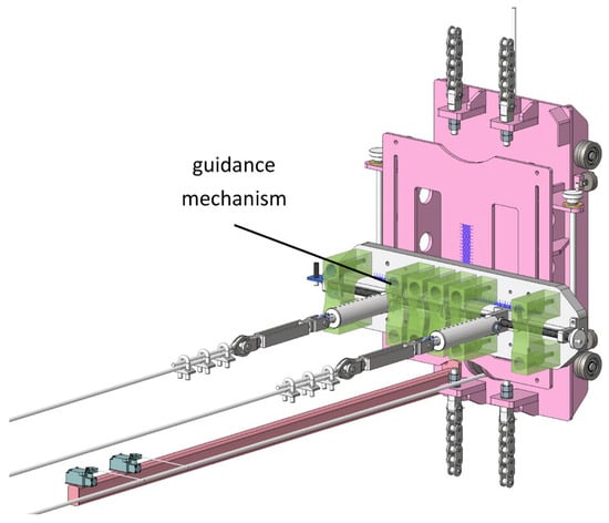
Figure 4.
The guiding mechanism.
Here, ε denotes the added mass coefficient, which typically ranges from 0.05 to 0.5. Accordingly, we performed a single-objective sensitivity analysis on the parameters within this range and found that the calculation results were insensitive to the variations in the added mass coefficient. Therefore, a value of 0.24 was adopted for ε in this study. The symbol m represents the mass of the water displaced by the vehicle.
3.1.3. Fluid Damping
In the underwater cyclic towing system, energy is dissipated not only through the system’s internal damping elements but also due to the external environment. As the underwater vehicle moves, it experiences damping forces arising from fluid viscosity [22]. These forces perform negative work, continuously converting the system’s vibrational mechanical energy into heat, thereby dissipating energy and affecting the system’s vibrational response. Therefore, when studying the system’s vibrational characteristics, it is essential to account for the impact of these forces. The energy dissipated by the fluid can be expressed as [23,24]:
Here, is the hydrodynamic damping force, the damping coefficient (0.248), the water density (998.2 kg/m3), A the flow-relative wetted area of the vehicle (0.126 m2), and v the relative flow velocity. These values are from ANSYS simulations. The energy dissipation from this damping force acts as an excitation input to the vehicle’s motion and is therefore incorporated into the corresponding elements of the damping matrix [25].
3.2. Parameters of the Underwater Towing System
The equivalent parameters for each system component were determined by analyzing the SolidWorks model, drawings, and field measurements of the underwater circulating towing system, and integrating them with the simplified model described above. The results are presented in Table 1. Additionally, the rotational frequency of the system’s traction motor is 3.22 Hz.

Table 1.
Parameters of the Underwater Towing Circulation System.
3.3. Analysis of the Natural Frequencies of the Underwater Towing System
As established previously, the operating conditions of the underwater circulating towing system are adjustable to meet experimental requirements. To evaluate the system’s performance, displacement data and other relevant parameters were collected from towing experiments conducted with an underwater vehicle at a depth of 2 m in a still-water pool at speeds of 1 m/s, 2 m/s, and 3 m/s. These data were substituted into Equation (10), and numerical simulations were performed using MATLAB to determine the system’s natural frequencies at different positions under these operating conditions, as shown in Figure 5. Since the first-order natural frequencies are relatively low, only the second- to fifth-order natural frequencies are presented here.
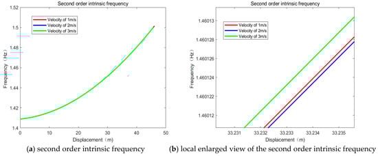
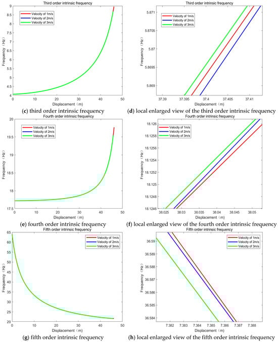
Figure 5.
Second- to Fifth-Order Natural Frequencies of the Underwater Towing System.
Figure 5 shows that the system’s natural frequencies at different orders vary continuously with the vehicle’s displacement but are nearly unaffected by the towing speed in the experiments. This suggests that the system is robust against small operational speed changes. Potential reasons include the cable stiffness and damping effectively mitigating the system’s sensitivity to speed, or that the speed variations simply do not introduce significant nonlinear effects to alter the system’s effective mass and stiffness. As a result, the natural frequencies remain stable with increasing speed.
The rotational frequency of the system’s traction motor is 3.22 Hz. Figure 5 shows that the system’s third-order natural frequency is initially close to this excitation frequency, indicating a risk of resonance during startup. Therefore, the system’s dynamic characteristics must be tuned to avoid resonant conditions.
3.4. Analysis of the Transient Vibration Response of the Underwater Circulating Towing System
The parameters determined previously were substituted into Equation (5). The transient vibration acceleration and displacement of the vehicle at speeds of 1 m/s, 2 m/s, and 3 m/s were then computed using the fourth-order Runge–Kutta method in MATLAB with the simulation step size set to 0.01 s. The results are presented in Figure 6.
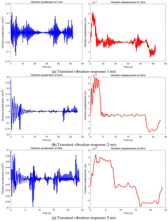
Figure 6.
Transient Vibration Response of the Vehicle at Different Speeds.
Figure 6 shows that the system experiences considerable vibrations at all operational speeds, with the most severe peaks in displacement and acceleration occurring at 2 m/s. This suggests that 2 m/s is a critical speed where the system’s dynamics are more complex, potentially due to its vibration frequency being closer to the towing device’s excitation frequency, creating near-resonant conditions. Therefore, vibration damping strategies are recommended to protect the experimental integrity and longevity of the platform.
4. Vibration Mitigation Measures for Underwater Towing Systems
4.1. Analysis of Mitigation Measures
To address system vibrations from the traction motor, the transmission path was optimized [26]. As shown in Figure 7, this approach involved installing damping rubber pads at the motor-frame interface to absorb energy at the source [27], while spring absorbers were used at the vehicle-rope connection to minimize energy transfer to the vehicle.
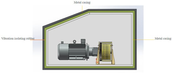
Figure 7.
Arrangement of the Rubber Vibration Isolator.
The vibration reduction strategy outlined above was applied to enhance the underwater circulating towing system. Additionally, dampers were incorporated into the original simplified system model, resulting in the improved system dynamics model shown in Figure 8. Subsequently, the vibration characteristics of the modified dynamic model will be analyzed to validate the effectiveness of the proposed strategy.
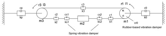
Figure 8.
Enhanced Dynamic Model of the Underwater Circulating Towing System.
4.2. Analysis of Vibration Damping Effectiveness
Analysis of Figure 8 indicates that the spring-damper and the towing rope are connected in series, thereby altering the overall stiffness of this segment. According to the principle of series springs [28], the equivalent stiffness between and is given by the reciprocal of the sum of the reciprocals of the individual stiffnesses, leading to the following equation:
Here, represents the equivalent stiffness of the spring-damper elements, while denotes the resultant equivalent stiffness. Since the rubber damper primarily suppresses low-frequency vibrations through its damping characteristics, its influence is considered here solely in terms of its contribution to the overall system damping [29]. The parameters introduced by the addition of vibration absorbers are substituted into the damping matrix and stiffness matrix . Specifically, is revised to , and is revised to , with and replaced by and . Subsequent calculations via Equation (9) reveal that a vibration reduction effect can be achieved when and fall within the ranges of to and to , respectively. To avoid abrupt changes in the system’s dynamic characteristics and deteriorated matching performance caused by adopting extreme parameter values, suitable non-extreme values within the aforementioned ranges are selected for subsequent calculation and analysis. Namely, the equivalent damping of the rubber vibration absorber is set as , and the equivalent stiffness of the spring vibration absorbers is specified as and .
The operating conditions under different speeds were respectively analyzed. A computational comparison of the system’s natural frequencies before and after the modification is presented in Figure 9. Furthermore, Figure 10 compares the vehicle’s vibration displacement and acceleration for the original and modified systems. As can be seen from Figure 5, the natural frequencies exhibit little difference at different speeds. Moreover, simulation analysis reveals that the improved results also show no significant discrepancy among themselves. Thus, only the variation in natural frequencies at a speed of 3 m/s is presented in Figure 9. The same applies below.
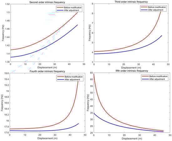
Figure 9.
Comparison of Modal Natural Frequencies Before and After System Modification.
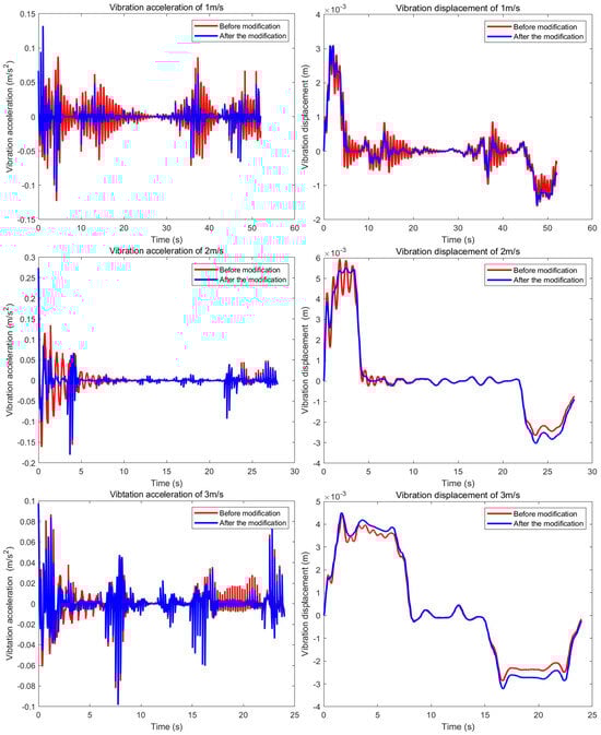
Figure 10.
Comparison of Vehicle Vibration Response Before and After Optimization.
As shown in Figure 9, the natural frequencies of the higher-order modes are significantly reduced following the system improvement. Furthermore, Figure 10 demonstrates that the combined action of the two damper types has substantially suppressed the vehicle’s vibration amplitude. This indicates that the rubber and spring dampers improve the vehicle’s operational stability, thereby effectively mitigating oscillations. However, a notable outcome is that the modifications have brought the system’s third-order natural frequency closer to the external excitation frequency, a phenomenon that warrants further investigation.
4.3. Effect of Tensioning Spring Stiffness on System Vibration
Although the introduced dampers reduce the vibration amplitude of the underwater vehicle, they paradoxically increase the system’s risk of resonance. Therefore, subsequent research will optimize the spring stiffness in the system’s tensioning device to explore a more effective vibration mitigation strategy.
Through relevant calculations, it was found that increasing the spring stiffness of the tensioning device could mitigate the vibration of the system. Therefore, based on this characteristic, and to ensure the effectiveness of vibration reduction as well as avoid adverse effects on the system caused by excessive stiffness variations, the spring stiffness parameter was set to . The comparative analysis of the system’s modal natural frequencies and transient vibration responses is presented in Figure 11 and Figure 12, respectively.
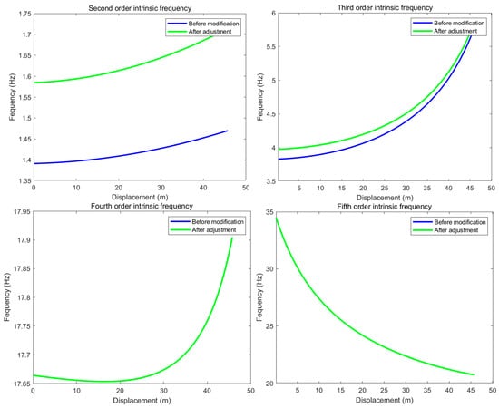
Figure 11.
Comparison of Modal Natural Frequencies Before and After System Modification.
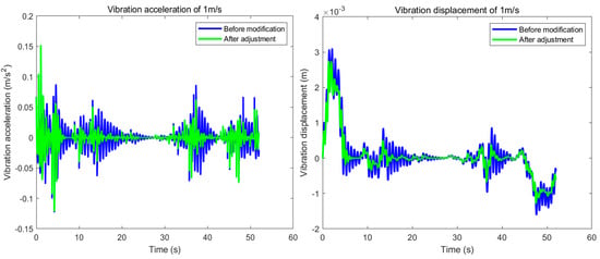
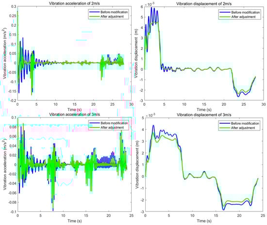
Figure 12.
Transient Vibration Response: Original vs. Optimized System.
Figure 11 and Figure 12 show that adjusting the spring stiffness of the spring tensioning device primarily affects the second and third-order natural frequencies of the improved system, shifting them away from the external excitation frequency. This adjustment also further reduces the vibration amplitude of the vehicle. Therefore, in addition to incorporating a damper, further increasing the spring stiffness not only helps to reduce the system’s vibrations but also shifts the third-order natural frequency away from the motor’s excitation frequency, thereby helping to prevent resonance at certain frequencies.
5. Parameter Optimization of the Underwater Circulating Towing System Using Simulated Annealing Particle Swarm Optimization
The effectiveness of the two damper types and the adjustment of tensioning spring stiffness in suppressing system vibrations has been demonstrated. However, the performance achieved under the parameter configurations provided above is unsatisfactory. Therefore, to achieve better vibration reduction, the subsequent work will adopt an optimization algorithm to optimize four parameters so as to improve the vibration reduction strategy proposed in this study.
5.1. Simulated Annealing Particle Swarm Optimization
The procedure of the Simulated Annealing Particle Swarm Optimization algorithm used in this study is as follows [30,31]:
- Initialize the particle swarm with an initial inertia weight w0 = 0.9 and learning factors c1 = 2.4 and c2 = 1.6.
- Based on the initial population, compute the fitness value of each particle. Record the personal best position (pbest) for each particle, the swarm’s global best position (gbest), and its fitness value (fgbest).
- The initial temperature is set as . This conventional formulation helps maintain a balance between the algorithm’s convergence speed and final solution quality.
- Update the position and velocity of each particle. To ensure algorithm convergence, the traditional velocity update formula is modified, while other components remain unchanged. The modified formula is:
In the formula above, ski denotes the convergence factor, and C (where C = c1 + c2) is the sum of the learning factors. Following the position and velocity updates, the fitness value of each particle is computed.
- 5.
- Following Step 4, the new particles are evaluated. This involves updating pbest and gbest based on fitness comparison, followed by a probabilistic acceptance check using the Metropolis criterion. The temperature is then iterated using the following scheme:
Here, α is the cooling coefficient (α = 0.95) and is the current temperature.
- 6.
- Update the inertia weight as follows:
Here, is the initial inertia weight, is the value at the final iteration, i is the current iteration number, and is the maximum number of iterations.
- 7.
- Repeat Steps 4, 5, and 6 until the algorithm reaches either the maximum number of iterations or the specified minimum temperature. When either condition is satisfied, the algorithm terminates and returns the global best position and its fitness value.
The flowchart is shown in Figure 13:
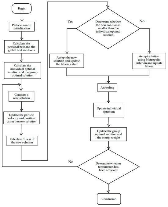
Figure 13.
Flowchart of the Simulated Annealing Particle Swarm Optimization Algorithm.
5.2. Selection of the Objective Function
For the underwater towed system, acceleration is a key performance indicator that effectively reflects the system’s operational state and is readily measurable with sensors. Therefore, this study employs the root mean square (RMS) of the vehicle’s vibration acceleration as the objective function for the optimization algorithm [32]. Since the vibration amplitudes of the vehicle differ from one another across its acceleration, constant-speed, and deceleration phases during operation, and the overall vibration acceleration during the acceleration and deceleration phases is more complex than that during the constant-speed phase, this study introduces weight coefficients to quantitatively distinguish these three operating conditions and further defines and constructs the objective function on this basis. Specifically, the RMS of the vibration acceleration during the acceleration phase (0–8 s) serves as the first-phase objective function, f1(x); the RMS during the constant-speed phase (8–16 s) serves as the second-phase function, f2(x); and the RMS during the deceleration phase (16–24 s) serves as the third-phase function, f3(x). Since these sub-objective functions belong to the same category and there is no order-of-magnitude difference between them, to facilitate the optimization process, a linear weighted combination approach is adopted to handle the single objective functions corresponding to each phase. This enables the integration of these sub-objective functions, transforming the multi-objective optimization into a single-objective optimization, as follows:
where is the objective function for the i-th phase, and is the corresponding weighting factor, with , , and . It can be seen from the literature that the range of is the resonance region, where denotes the excitation frequency and represents the natural frequency of the system [33]. Therefore, to ensure that the optimized results can avoid the resonance phenomenon of the system, constraints are imposed on the optimized parameters; i.e., .
5.3. Parameter Range Constraints
To enhance the optimization efficiency, bound constraints were applied to the following parameters: the equivalent stiffness values and of the spring-damper elements, the equivalent damping of the rubber damper, and the equivalent stiffness of the tensioning spring. The specific bounds for these parameters are listed in Table 2.
Table 2.
Parameter Bounds.
In conclusion, in this study, the minimum root mean square vibration acceleration f(x) during vehicle operation is taken as the parameter optimization objective for the vibration damping rubber, spring dampers, and spring tension devices. Since it is necessary to achieve the vibration damping effect while preventing resonance, this study adopts avoiding resonance as a constraint. Therefore, the parameter optimization model established in this study can be mathematically expressed as:
Here, represents the design variables, denoting the equivalent stiffness of the spring tension device, the equivalent damping of the vibration damping rubber, the equivalent stiffness of the vessel’s right-side spring damper, and the equivalent stiffness of the vessel’s left-side spring dampers; and represent the lower and upper bounds of the design variables; is the external excitation frequency, and is the natural frequency of the system.
5.4. Optimization Process and Analysis of Results
For this analysis, the operating condition at 3 m/s was selected to optimize the parameters of the spring-damper elements, rubber dampers, and the tensioning spring in the improved underwater circulating towing system. The initial parameters for the Simulated Annealing Particle Swarm Optimization algorithm were set as follows: a population size of 50, a maximum of 200 iterations, a cooling coefficient of 0.95, and a convergence criterion of .
As shown in Figure 14, the objective function value decreases steadily with each iteration and stabilizes after the 125th iteration. This indicates that the algorithm has converged, producing the optimized parameters for the two dampers and the tensioning spring in the improved underwater cyclic towing system, as presented in Table 3:
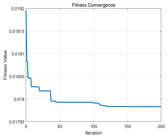
Figure 14.
Fitness Convergence Curve.
Table 3.
Results of Optimization.
By incorporating the optimized parameters from Table 3 into the system’s dynamic and vibration equations, a comparative analysis was conducted. Figure 15 and Figure 16 present the comparison of the system’s natural frequencies and transient vibration responses before and after optimization.
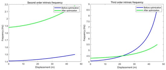
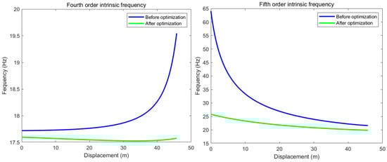
Figure 15.
Comparison of Natural Frequencies Before and After Optimization.
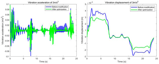
Figure 16.
Comparison of the transient responses before modification and after optimization.
Based on Figure 15 and Figure 16, and Table 4, the parameter optimization resulted in a 6% increase in the system’s third-order natural frequency, effectively preventing potential resonance during operation. Furthermore, it reduced the vehicle’s vibration displacement and acceleration by 45.8% and 20%, respectively, thereby significantly enhancing operational stability. These findings confirm that the vibration mitigation strategy substantially suppresses the system’s vibration amplitude. The method also demonstrates robust adaptability, allowing for rapid adjustments to meet specific operational requirements in diverse environments, which ensures stable performance.
Table 4.
Comparison of Third-Order Natural Frequency and Vehicle Vibration Response.
6. Conclusions
This study developed a dynamic model for the underwater cyclic towing system by adopting a methodology from traction elevator systems. From this model, the system’s vibration equation was derived. Numerical solution and analysis revealed a potential for resonance and operational instability. To mitigate these issues, we enhanced the system by incorporating spring-damper elements, adding a rubber damper, and adjusting the tensioning spring stiffness. Furthermore, the parameters of these components—including the equivalent stiffness of the spring-dampers, the equivalent damping of the rubber damper, and the stiffness of the tensioning spring—were optimized using the Simulated Annealing Particle Swarm Optimization (SA-PSO) algorithm, which led to improved vibration suppression. The main conclusions of this work are as follows:
- (1)
- Although incorporating spring-damper elements and a rubber damper can reduce vibration amplitude and enhance vehicle stability, this strategy has a significant limitation: it drives the system’s third-order natural frequency closer to the external excitation frequency, thereby increasing the risk of resonance.
- (2)
- Adjusting the stiffness of the tensioning spring, in addition to employing dampers, not only further reduces the vehicle’s vibration amplitude but also increases the system’s third-order natural frequency. This effectively prevents resonance and enhances operational stability and safety.
- (3)
- The vibration reduction strategy was further refined using the Simulated Annealing Particle Swarm Optimization algorithm. The optimization results show a 6% increase in the system’s third-order natural frequency, effectively preventing resonance, and reductions in the vehicle’s average vibration displacement and acceleration by 45.8% and 20%, respectively, thereby improving operational stability. Moreover, the proposed approach demonstrates strong adaptability, allowing for performance adjustments to meet specific requirements in various environments. It thus provides an effective solution for vibration control in such systems and holds significant potential for widespread application.
Author Contributions
Methodology, S.L.; Software, S.L.; Validation, S.L.; Formal analysis, S.L.; Writing—original draft, S.L.; Writing—review and editing, Q.W.; Supervision, Q.W. All authors have read and agreed to the published version of the manuscript.
Funding
This research received no external funding.
Institutional Review Board Statement
Not applicable.
Informed Consent Statement
Not applicable.
Data Availability Statement
The raw data supporting the conclusions of this article will be made available by the authors on request.
Conflicts of Interest
The authors declare no conflicts of interest.
References
- Vangi, M.; Topini, E.; Liverani, G.; Topini, A.; Ridolfi, A.; Allota, B. Design, Development, and Testing of an Innovative Autonomous Underwater Reconfigurable Vehicle for Versatile Applications. IEEE J. Ocean. Eng. 2025, 50, 509–526. [Google Scholar] [CrossRef]
- Neha, B.; Krishnan, A.S.; Younas, M.T.A.; Sunil, A.; Raji, T.R. Marine Inspection: Implementation and Advanced Applications of a Remotely Operated Underwater Robot for Exploration in Challenging Marine Environments. In Proceedings of the 2024 Second International Conference on Smart Technologies for Power and Renewable Energy (SPECon), Ernakulam, India, 2–4 April 2024; IEEE: New York, NY, USA, 2024; pp. 1–4. [Google Scholar] [CrossRef]
- Wu, J.; Yang, X.; Xu, S.; Han, X. Numerical Investigation on Underwater Towed System Dynamics Using a Novel Hydrodynamic Model. Ocean. Eng. 2022, 247, 110632. [Google Scholar] [CrossRef]
- Tian, L.; Chen, X.X.; Zhu, Z.L. Numerical Calculation and Analysis of Low-Noise Towing Test Platform. Mech. Electr. Eng. Technol. 2022, 51, 185–190. [Google Scholar]
- Oladele, O.; Brizzolara, S. Modeling the Dynamics of an Autonomous Underwater Vehicle (AUV) Towing Another AUV with a Marine Cable. In Proceedings of the OCEANS 2022, Hampton Roads, VA, USA, 17–20 October 2022. [Google Scholar]
- Yang, J.; He, L.; Shuai, C. Experimental Study on U-Turn Motion of Underwater Towing System. J. Naval Univ. Eng. 2018, 30, 26–31. [Google Scholar]
- Park, J.; Rhee, S.H.; Im, J.; Ji, B.; Lee, S. Experimental Study on the Towing Stability of a Towed Underwater Object. Int. J. Nav. Archit. Ocean. Eng. 2023, 15, 100539. [Google Scholar] [CrossRef]
- Tian, Z.; Liu, Q. Design of Hoisting Winch for Underwater Towing System. Mech. Manag. Dev. 2015, 30, 13–15. [Google Scholar]
- Schuch, E.M.; Linklater, A.C.; Lambeth, N.W.; Wooslez, C.A. Design and Simulation of a Two Stage Towing System. In Proceedings of the OCEANS 2005 MTS/IEEE, Washington, DC, USA, 17–23 September 2005. [Google Scholar]
- Wu, J.; Jin, X.; Chen, J.; Xu, Y.; Lu, L.; Chen, Y. Experimental Observation on a Controllable Underwater Towed Vehicle with Vertical Airfoil Main Body. In ASME 2015, Proceedings of the 34th International Conference on Ocean, Offshore and Arctic Engineering, St. John’s, NL, Canada, 21 May–5 June 2015; American Society of Mechanical Engineers: New York, NY, USA, 2015. [Google Scholar]
- Pallayil, V.; Chitre, M.A.; Deshpande, P.D. A Digital Thin Line Towed Array for Small Autonomous Underwater Platforms. In Proceedings of the Oceans 2007, Vancouver, BC, Canada, 29 September–4 October 2007. [Google Scholar]
- Sakai, H.; Tanaka, T. Underwater Observation System Using Autonomous Towed Vehicle. In Proceedings of the Oceans ’04 MTS/IEEE Techno-Ocean ’04, Kobe, Japan, 9–12 November 2004. [Google Scholar]
- Zhauyt, A.; Musayev, J.; Bazanova, I.; Mustapaev, K. Equations of Motion for the Rigid and Elastic Double Pendulum Using Lagrange’s Equations. Vibroeng. Proc. 2025, 58, 154–160. [Google Scholar] [CrossRef]
- Rieman, L.P.; Buckley, R.M.; Shinde, N.S.; Wheeler, S.J. A modified linear-elastic model for calibration of resonant column devices accommodating drive system compliance. Geotechnique 2025, 75, 622–636. [Google Scholar] [CrossRef]
- Sun, J.; Xu, P.; Chen, M.; Xue, J. Forced Vibration of Time-Varying Elevator Traction System. Stroj. Vestn.-J. Mech. Eng. 2024, 75, 170–180. [Google Scholar] [CrossRef]
- Li, X.; Wu, L.; Li, L. Analysis of the Dynamic Characteristics of Elevator Mechanical Systems. Mech. Eng. 2007, 41–43. [Google Scholar] [CrossRef]
- Wang, Z.B. Dynamics and Design of Marine Towing Systems; Defense Industry Press: Beijing, China, 2019. [Google Scholar]
- Wu, J. Research and Optimization Design of the Vertical Vibration Dynamic Characteristics of Elevator Car. Master’s Thesis, Zhengzhou University, Zhengzhou, China, 2020. [Google Scholar]
- Almohimd, T.; Bhalla, S.; Madan, A. Simplified Operational Modal Analysis Using Piezo Sensors: Leveraging Minimal Sensors and Field-Centric. e-J. Nondestruct. Test. 2025, 30, 9–12. [Google Scholar] [CrossRef] [PubMed]
- Perrault, D.; Bose, N.; O’Young, S.; Williams, C.D. Sensitivity of AUV Added Mass Coefficients to Variations in Hull and Control Plane Geometry. Ocean. Eng. 2003, 30, 645–671. [Google Scholar] [CrossRef]
- Pan, X. Fluid Mechanics and Heat Transfer; Jiangxi Higher Education Press: Nanchang, China, 2019. [Google Scholar]
- Yang, R.; Clement, B.; Mansour, A.; Li, M.; Wu, N. Modeling of a Complex-Shaped Underwater Vehicle for Robust Control Scheme. J. Intell. Robot. Syst. 2015, 80, 491–506. [Google Scholar] [CrossRef]
- Yao, Z.; Liu, B.; Zeng, Y.; Bai, M.; Wang, F. Vibration Damping Measurement and Simulation of a Rotating Disk in Water. Trans. Beijing Inst. Technol. 2024, 44, 377–385. [Google Scholar]
- Moraga, G.; Xia, X.; Roig, S.; Valero, C.; Valentin, D.; Egusquiza, M.; Zhou, L.; Egusquiza, E.; Presas, A. Experimental study on the influence of vibration amplitude on the fluid damping of a submerged disk. J. Sound Vib. 2024, 569, 118099. [Google Scholar] [CrossRef]
- Gai, D. Research on the Energy Dissipation and Suppression Mechanism of Orthogonal Structural Viscous Damping. Ph.D. Thesis, Jilin University, Changchun, China, 2024. [Google Scholar]
- Ucar, H.; Basdogan, I. Dynamic Characterization and Modeling of Rubber Shock Absorbers: A Comprehensive Case Study. J. Low Freq. Noise Vib. Act. Control. 2018, 37, 509–518. [Google Scholar] [CrossRef]
- Shreehari, J. Vibration Damping through Natural Rubber and NBR Rubber. Res. Sq. 2023. [Google Scholar] [CrossRef]
- Wu, H. Study on the Dynamic Characteristics of High-Speed Traction Elevator. Ph.D. Thesis, Nanjing University of Aeronautics and Astronautics, Nanjing, China, 2013. [Google Scholar]
- Miao, Q. Study on the Vibration Damping Performance of the Rubber Floor Vibration Damping System for High-Speed Trains. Master’s Thesis, Qingdao University of Science and Technology, Qingdao, China, 2017. [Google Scholar]
- Fontes, D.B.M.M.; Homayouni, S.M.; Goncalves, J.F. A Hybrid Particle Swarm Optimization and Simulated Annealing Algorithm for the Job Shop Scheduling Problem with Transport Resources. Eur. J. Oper. Res. 2023, 306, 1140–1157. [Google Scholar] [CrossRef]
- Harjian, M.R.; Penangsang, O.; Aryani, N.K. Economic Dispatch Steam Power Plant Jeranjang and Sambelia Using Hybrid Algorithm Particle Swarm Optimization and Simulated Annealing. In Proceedings of the 2023 International Seminar on Intelligent Technology and Its Applications (ISITIA), Surabaya, Indonesia, 26–27 July 2023; IEEE: New York, NY, USA, 2023. [Google Scholar]
- Lai, Y.; Wu, J.; Wang, K. Optimization Design of Vertical Vibration Parameters for High-Speed Elevators Based on Multi-Objective Genetic Algorithm. J. Univ. Jinan (Nat. Sci. Ed.) 2023, 37, 108–115. [Google Scholar]
- Zhang, Y. Discussions on Mechanical Vibration; Science Press: Beijing, China, 2010. [Google Scholar]
Disclaimer/Publisher’s Note: The statements, opinions and data contained in all publications are solely those of the individual author(s) and contributor(s) and not of MDPI and/or the editor(s). MDPI and/or the editor(s) disclaim responsibility for any injury to people or property resulting from any ideas, methods, instructions or products referred to in the content. |
© 2026 by the authors. Licensee MDPI, Basel, Switzerland. This article is an open access article distributed under the terms and conditions of the Creative Commons Attribution (CC BY) license.