Abstract
The process of decision-making for machining box-type components plays a crucial role in the technological design of mechanical components. Currently, the selection of process parameters for box-type parts often relies on designers consulting manuals or on personal experience. Moreover, different designers utilize independent and heterogeneous Computer-Aided Process Planning (CAPP) systems, leading to uncertainties in process design and difficulties in sharing and transmitting process knowledge. This paper proposes an ontology-based process decision-making method for the planar machining of box-type parts to infer the appropriate machining process parameters. First, a hierarchical information representation model for process decision-making in planar machining is constructed to describe the decision-making process. Second, an ontology model for process decision-making in planar machining is developed based on relevant concepts and relationships involved in the decision-making process. Third, reasoning rules for planar machining process decisions are established using Semantic Web Rule Language (SWRL), incorporating part feature information and process knowledge to infer reasonable process methods and operation dimensions. Finally, a case study of gear transmission housing is presented to illustrate the working process of the proposed method and verify its effectiveness.
1. Introduction
As fundamental components of machines, box-type components have relatively complex structures, primarily due to their thin and unevenly distributed walls, as well as the presence of various geometric planes and numerous holes, all of which must meet high-precision manufacturing requirements. In traditional process design, the selection of process parameters for box-type components surfaces often relies on designers consulting design manuals or drawing upon personal experience. This approach places high demands on skilled process designers and, due to individual differences in understanding, can lead to uncertainty in design results [1,2], thereby affecting the consistency of process design. This issue has become a key factor limiting the intelligent advancement of process decision-making for box-type parts.
To address this, the academic community has proposed numerous methods to investigate the process design of box-type components. Deja M. [3] introduced a feature-based reasoning method, which utilizes an extended feature classification approach, considering the working direction and position of machining features relative to reference datums, and which generates machining sequences based on part setup and machine tool alternatives for turning and milling components. Duan J. [4] proposed a machining process program based on knowledge representation learning, which maps entities and relationships of machining graph models to dense low-dimensional vectors using the TransD algorithm, and clusters vectors to obtain parts with similar operation sequences, identical cutting tools, and machine tool machining. LeoKumar [5,6] suggested using XML to extract machining process features of product parts, while employing the FBM method for part modeling, and utilizing a knowledge-based system approach to select process parameters for given micro-features, thereby achieving the intelligent selection and optimization of process parameters. Zhai [7] proposed a three-dimensional process planning method based on machining elements, which extracts all machining elements for a part, employs a hybrid algorithm combining simulated annealing and ant colony optimization to optimize the process route decision-making method for box-type parts, and provides a feature-based operation model generation method. Zhu [8] introduced a three-dimensional digital process design method based on MBD, which integrates MBD with knowledge engineering technology, applies knowledge engineering technology for process decision-making, and introduces ontology technology to describe process knowledge, enabling process information to be displayed in a three-dimensional environment.
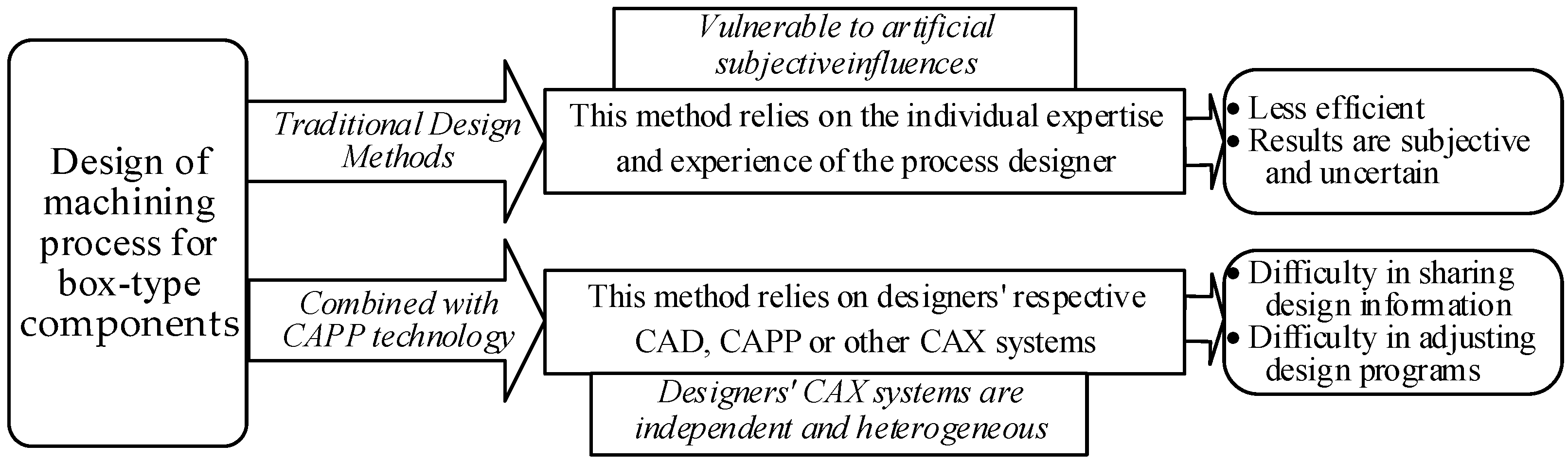
Although existing research has made progress in the automation of process decision-making for machining box-type parts, the independence and heterogeneity of CAX systems used in different studies hinder the sharing and transmission of process knowledge, significantly limiting the efficiency of process design (as illustrated in Figure 1).To address this issue, this study focuses on the planar machining of box-type parts and introduces ontology technology into process decision-making under the premise that the machining datum coincides with the design datum. As a formalized specification for shared conceptual models, ontology offers significant advantages in enhancing semantic interoperability among heterogeneous systems, strengthening knowledge sharing, and promoting knowledge reuse [9,10]. Considering the requirements of artificial intelligence and its application in manufacturing, this study constructs an ontology-based knowledge base for box-type parts. This approach reduces uncertainty in machining process decision-making, improves process design efficiency, and establishes an efficient information exchange platform for process design, thereby advancing the intelligentization of process decision-making for box-type parts.
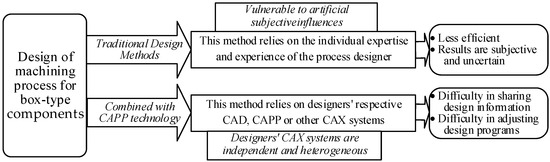
Figure 1.
Schematic diagram of the study background.
Based on this research background, the structure of this paper is organized as follows: Section 2 reviews relevant studies; Section 3 provides an in-depth analysis of the planar machining process for box-type parts and employs an adjacency matrix method to construct a hierarchical information model for process decision-making, representing part feature information, machining schemes, process parameters, and their interrelationships; Section 4 systematically classifies and summarizes the concepts and terminologies involved in planar machining process decision-making and develops an ontology model using the Web Ontology Language (OWL); Section 5 establishes reasoning rules for process decision-making using the Semantic Web Rule Language (SWRL) based on theoretical principles and process design manuals, leveraging ontology reasoning mechanisms to enable the automatic generation of machining methods and process parameters for box-type parts; finally, Section 6 develops an algorithm for planar machining process decision-making and validates the feasibility and effectiveness of the proposed method through a case study.
2. Related Work
In recent years, ontology-based research has gained significant attention as a prominent field of study. Its key advantages lie in enabling semantic representation, intelligent reasoning, semantic interoperability, and knowledge reuse [11]. Originally derived from the field of philosophy, ontology technology has been widely applied in computer science. With continuous advancements in technology, ontology has increasingly been integrated into multiple disciplines, leading to its expanding application domains [12,13,14,15].
In the field of machining process design, numerous scholars have conducted in-depth research on the application of ontology technology. Liu [16] proposed an ontology-based knowledge representation model for the manufacturing domain, which employs semantic analysis and extraction to annotate knowledge and construct a computer-recognizable and processable semantic space model. Zhong [17] applied ontology technology to the automatic generation of assembly sequences, developing an assembly information representation model and constructing domain ontologies and reasoning rules to achieve automatic assembly sequence generation. Yu [18] designed an ontology for ASP-based assembly and employed rule-based reasoning to determine the priority relationships of part installation. Chen [19] proposed an automatic disassembly decision-making method for mechanical products based on ontology and case-based reasoning. Peng [20] introduced a geometric tolerance semantics (GTS) representation model based on GeoSpelling, and established a tolerance knowledge ontology model using OWL to verify the rationality of 3D annotated tolerance information. Shi [21] et al. proposed a semantic simplification method for assembly accuracy of mechanical products, which generates simplified assembly accuracy information by using ontology technology to establish the semantic relationship between the assembly accuracy and design tolerance of a part. He [22] proposed an ontology-based knowledge modeling method for remanufacturing process planning, utilizing ontology to systematically organize and formalize remanufacturing-related information from different sources and lifecycle stages. Wang [23] investigated the automatic generation of process dimension parameters for shaft-type parts based on ontology, and developed an ontology model for process dimension parameter generation.
In addition, ontology-related research has also been reflected in various aspects, including ontology representation, ontology construction, ontology development, and ontology reasoning.
- (1)
- Ontology Representation
The formal semantic representation of an ontology is a prerequisite for ensuring that computers can recognize and process it. An effective ontology representation language facilitates information exchange and sharing between different systems [24]. Common ontology representation languages include RDFS, OIL, DAML+OIL, and OWL. Among them, OWL (Web Ontology Language) exhibits superior expressive power in knowledge representation and formal definition. OWL is based on Description Logic (DL), ensuring decidability in reasoning and offering highly efficient inferencing capabilities [25].
- (2)
- Ontology Construction
Ontology construction refers to the formalization of concepts and their relationships [26]. Common ontology construction methodologies include the Skeleton method, Tove method, Methontology method, Sensus method, Cyclic Acquisition method, Five-Step Cyclic method, and the Seven-Step method [27]. Among these, the Seven-Step method offers significant advantages, particularly in its wide applicability and well-defined steps. This method, proposed by Noy and McGuinness at Stanford University in 2001, has been widely adopted in the field of mechanical engineering.
- (3)
- Ontology Development
Ontology development involves the use of specialized tools for constructing, editing, and maintaining ontologies. Various ontology development tools have been introduced, among which the most mature and widely used include Protégé, Ontolingua, Ontosaurus, WebOnto, and OntoEdit [28]. Protégé, developed in Java, is currently the most extensively used ontology development tool. It allows users to define classes, attributes, and constraints while supporting multiple ontology representation languages. Additionally, Protégé is highly compatible with other software systems and offers strong extensibility, making it a key tool in ontology development.
- (4)
- Ontology Reasoning
The core of ontology reasoning lies in developing algorithms that are terminable, reliable, decidable, and efficient. OWL demonstrates strong capabilities in representing structured knowledge with interrelated components and in describing and constraining individual objects. However, it lacks expressiveness in handling complex relationships such as causality [29]. To address this limitation, the W3C developed the Semantic Web Rule Language (SWRL) [30], which enables effective rule representation within ontology knowledge bases using OWL classes and properties. SWRL provides powerful rule-expressiveness, high versatility, and the seamless integration of ontologies with rule-based reasoning.
In summary, the existing studies have not integrated ontology technology with process decision-making for box-type parts. Therefore, building upon the research in [23], this study incorporates ontology technology to construct a hierarchical information representation model for process decision-making in the planar machining of box-type parts. Based on this model, the Web Ontology Language (OWL) and the Seven-Step method are employed to transform the information representation model into an ontology-based process decision model. Furthermore, SWRL (Semantic Web Rule Language) is utilized to establish inference rules, enabling the automatic generation of machining methods and process parameters for the planar machining of box-type parts through ontology reasoning.
A comprehensive analysis of existing research reveals that no prior studies have integrated ontology technology into process decision-making for box-type parts. Building upon the findings of [23], this study develops a hierarchical information representation model for the planar machining process decision-making of box-type parts. Based on this model, the Web Ontology Language (OWL) and the Seven-Step method are employed to convert the information representation model into an ontology-based process decision model. Additionally, SWRL is utilized to establish inference rules, allowing the ontology reasoning mechanism to automatically generate machining methods and process parameters for planar machining of box-type parts.
3. Constructing a Hierarchical Information Model for Process Decision-Making
3.1. Planar Machining Process Decision-Making
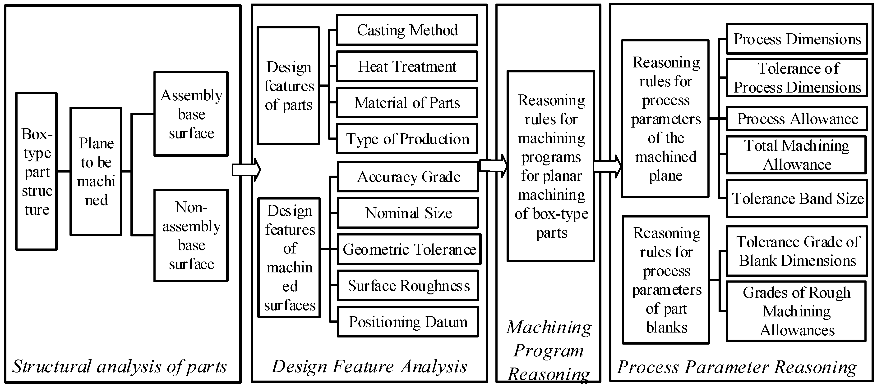
The process decision-making for planar machining of box-type parts is a crucial component of the overall process design. Its primary role is to determine the machining scheme and process parameters for planar surfaces, while ensuring precise interpretation of process information. This facilitates efficient utilization of machining data throughout the entire lifecycle of box-type part manufacturing [31]. The decision-making process for planar machining of box-type parts involves multiple stages, including structural analysis, design feature analysis, inference of machining schemes, and selection of process parameters, as illustrated in Figure 2.
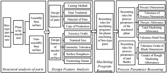
Figure 2.
Decision-making process for planar machining of box-like parts.
(1) Structural Analysis of the Part: This stage aims to analyze the structure of the box-type part and identify the planar features that require machining.
(2) Design Feature Analysis: In this phase, a detailed analysis of the design features of both the box-type part and the target machining planes is conducted. The results of this analysis provide essential prerequisites for subsequent machining scheme inference and process parameter reasoning.
(3) Machining program Reasoning: Based on the design feature information of the part and its machining planes, machining schemes for various machining features are derived. These inferred machining schemes serve as the foundation for process parameter reasoning in the next step.
(4) Process Parameter Reasoning: Following the design feature information of the target machining planes and the inferred machining schemes, specific process parameters for the machining planes are determined in accordance with relevant process design rules. Additionally, the process parameters for the raw part blank are generated directly based on the part’s feature information and process design rules.
3.2. Hierarchical Information Representation Model for Machining Process Decision-Making
The adjacency matrix model, known for its simplicity, clarity, ease of implementation, and effectiveness in representing hierarchical relationships, has been widely applied in the field of mechanical manufacturing [24]. To comprehensively and adequately represent the relationships among various entities involved in the decision-making process of planar machining for box-type parts, this study adopts the adjacency matrix as a descriptive tool.
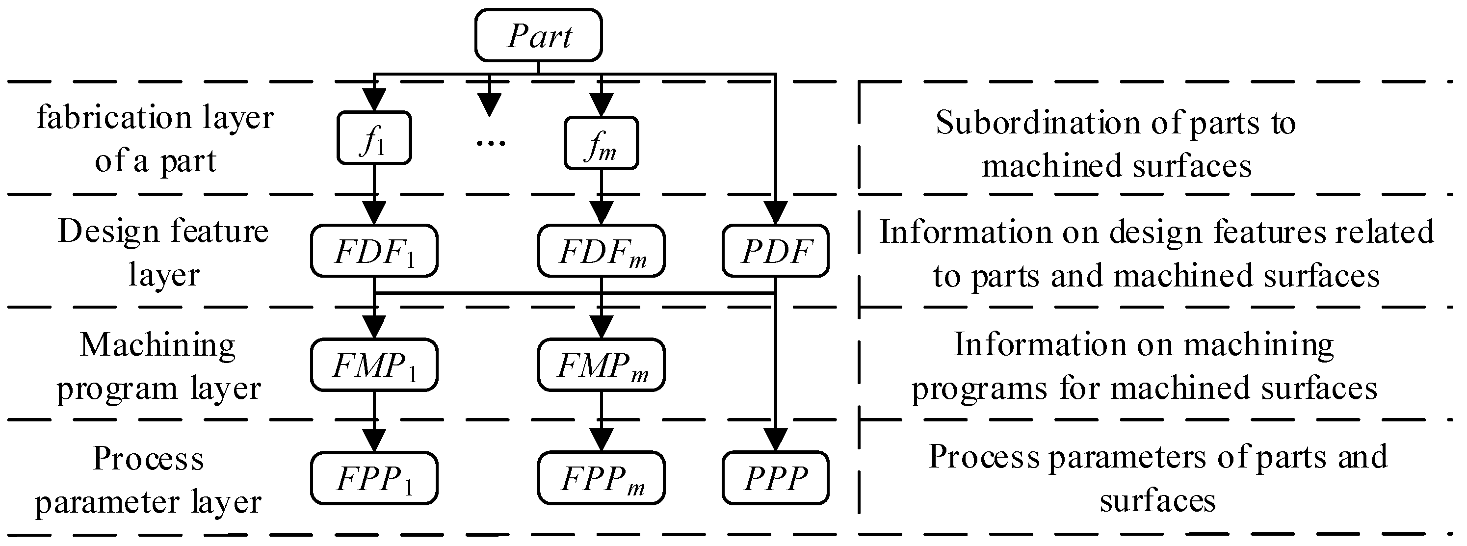
A hierarchical information representation model for the planar machining process decision-making of box-type parts is constructed, consisting of four interconnected layers: the part structure layer, design feature layer, machining scheme layer, and process parameter layer, as illustrated in Figure 3.
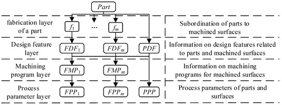
Figure 3.
Hierarchical model for decision-making in planar machining process of box-type components. Note: Part—box-yype components; fm—plane being machined (m = 1, 2, 3, ⋯); FDFm—related design features of the plane being machined; PDF—related design features of the part; FMPm—flat machining program; FPPm—process parameters of the machined plane; PPP—process parameters of the blank.
3.2.1. Part Structure Layer
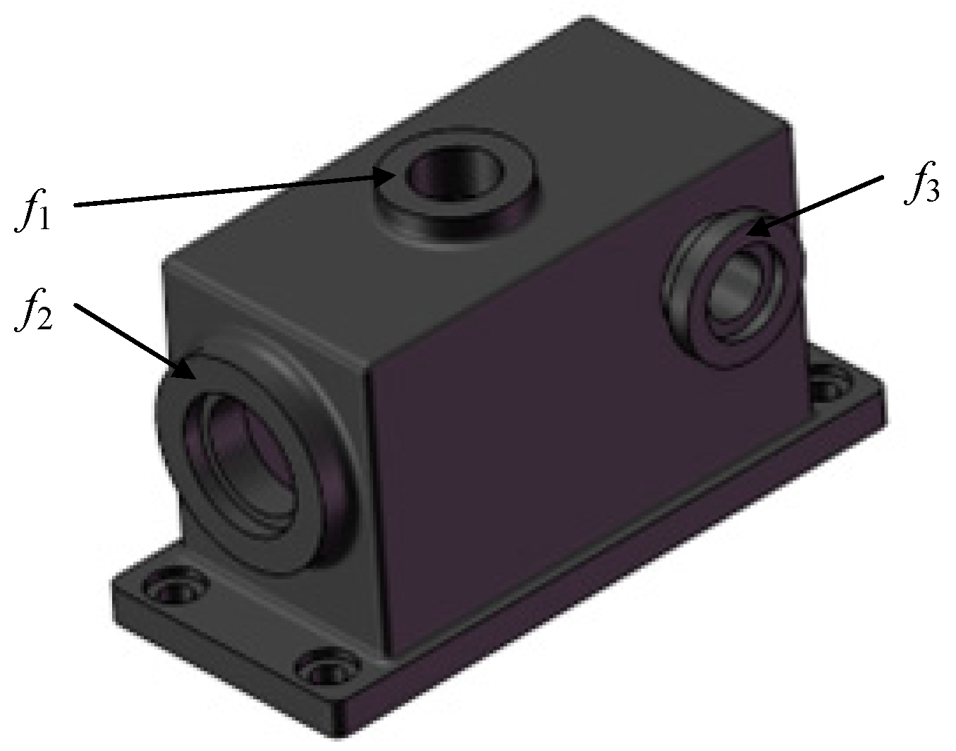
The “Part Structure Layer” constitutes the foundational tier of the hierarchical model for the planar machining process decision-making of box-type parts. The primary function of this layer is to decompose the box-type component into multiple machinable surfaces and represent the subordinate relationships between the box-type parts and its respective machinable surfaces. This serves as a fundamental basis for the subsequent tiers within the hierarchical model, as illustrated in Figure 4.
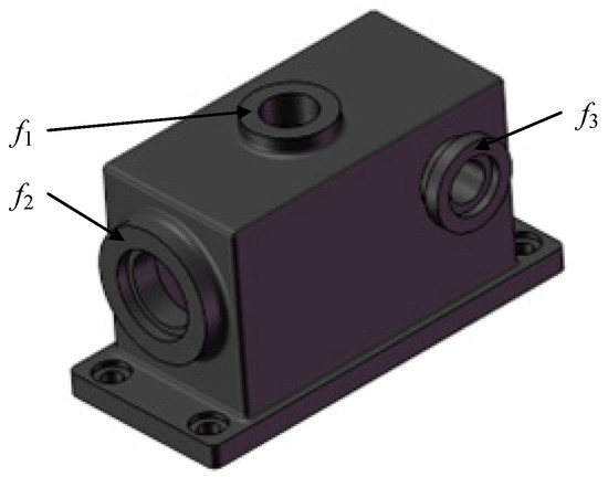
Figure 4.
Subordination of case parts to the plane to be machined.
3.2.2. Design Features Layer
The “Design Features Layer” represents the second tier of the hierarchical model for the planar machining process decision-making of box-type parts. The primary function of this layer is to extract design feature information related to process decision-making for the box-type parts and its planar surfaces from the part model. Additionally, it establishes the subordinate relationships between the part, its planar surfaces, and their corresponding design feature information. Design features relevant to planar machining process decision-making for box-type parts include both part design features and machined surface design features, as illustrated in Figure 5.
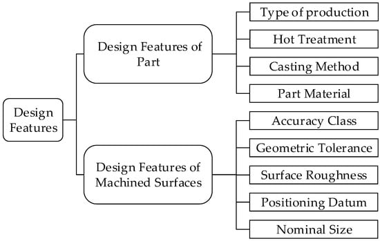
Figure 5.
Design features of box-type components and their machined surfaces.
The design features of the box-type parts encompass several key aspects, including production type (PT), heat treatment (HT), casting method (CM), and material composition (PM). The conceptual set representing these design features is formulated as shown in Equation (1) [32].
PDF = { PT, HT, CM, PM }.
- Production types (PT) can be classified into small-batch production, medium-batch production, and large-batch production.
- Common materials (PM) for box-type parts include cast steel, gray cast iron, and ductile iron.
- Casting methods (CM) typically used for box-type parts involve sand casting (manual molding and machine molding), shell molding, metal mold casting, and investment casting.
- Heat treatment methods (HT) commonly applied to box-type parts include annealing, normalizing, aging treatment, and quenching.
The design features of the machined surface primarily include basic dimensions (BD), length (Len), width of machined surfaces (Wid), surface roughness (Ra), economic accuracy class (IT), nominal dimensional tolerance (NDT), geometrical tolerance constraints (GT), geometrical tolerance class (GTC), and positioning reference (PR). The conceptual set representing these design features is defined in Equation (2).
FDF = { BD, Len, Wid, Ra, IT, NDT, GT, GTC, PR }.
For planar machining, positioning references can be categorized into coarse datum and fine datum. As described in Reference [32], geometrical tolerance constraints can be classified into straightness, flatness, parallelism, and perpendicularity.
3.2.3. Processing Program Layer
The “Processing Program Layer” constitutes the third tier of the hierarchical model for planar machining process decision-making of box-type parts. The primary function of this layer is to generate machining plans for each machinable surface of the box-type component and to establish the subordinate relationships between the design feature information and the corresponding machining plans. A planar machining plan consists of a chain of machining methods arranged in a specific sequence, following the “roughing first, then finishing” principle. The reasonable machining plan is derived through process knowledge based on the design features of the machinable surfaces, including precision grade, design dimensions, geometric constraints, and surface roughness. Some machining plans for planar surfaces of box-type parts are summarized in the literature [32] and relevant empirical knowledge, as presented in Table 1. The relationship between certain machining plans for box-type components and their geometric tolerance constraints is shown in Table 2 and Table 3.

Table 1.
Selection of plane machining schemes.
Table 2.
Machining program selection under geometric tolerance constraints (1).
Table 3.
Machining program selection under geometric tolerance constraints (2).
For example, if the accuracy class of the machined surface is IT10, the surface roughness is 6.3 μm, and the surface has not undergone quenching, while it has a flatness geometrical tolerance constraint with a tolerance class of grade 11, then the appropriate machining scheme would be “Rough milling—Semi-finish Milling”. This machining scheme is designated as CMP2, meaning that the first machining operation for this surface is rough milling, followed by semi-finish milling. These two operations together ensure that the required specifications are met.
3.2.4. Process Parameter Layer
The “Process Parameters Layer” represents the lowest level in the hierarchical decision-making model for the machining process of box-type components. This layer primarily functions to generate the blank dimensional parameter information and the process parameters information for the machined surfaces of box parts. The blank dimensional parameter information includes the Dimensional Tolerance Grade (DTG) and the Machining Allowance Grade (MAG). The process dimensional parameter information for the machined surfaces consists of the Machining Dimension (MD), Machining Dimension Tolerance (MDT), Tolerance Zone Dimension (TTS), Machining Allowance (MA), and Total Machining Allowance (TMA). The blank dimensional parameter information (PPP) and the process parameter information of the machined surfaces (FPP) can be represented using conceptual sets, as shown in Equations (3) and (4).
PPP = { DTG, MAG }.
FPP = { MD, MDT, TTS, MA, TMA }.
In the machining process of box-type components, there are two scenarios: one where the design reference and the locating reference coincide, and another where they do not. However, in most cases, the references coincide [33]. Therefore, this paper focuses on the scenario where the design reference and the locating reference coincide during the flat machining of the box-type component. As the machined surfaces of box-type parts are processed sequentially from the first operation to the last, the process dimensions for the flat machining of the box-type parts are determined using a reverse calculation method. Specifically, the design dimensions and tolerances from the part drawing are used to iteratively calculate the machining allowances and accuracy for each operation, ultimately determining the blank dimensions [33]. This approach is detailed in Equation (5), which provides the process dimension parameters.
Gy = Gy0 + TZ.
In the formula, “Gy0” represents the dimension of the machined surface from the previous operation, “Gy” is the process dimension to be achieved in the current operation, and “TZ” denotes the machining allowance for the current operation.
4. Ontology Modeling for Process Decision-Making
The decision-making process for box-type planar machining relies on the informatization and representation of knowledge within the process. The hierarchical model established above primarily illustrates the concepts and their hierarchical relationships involved in machining process decision-making, but falls short of conveying complete semantics. Among various methods of information representation, ontology demonstrates significant advantages in structuring conceptual hierarchies, semantic expression, knowledge reasoning, and information sharing [24,34]. The decision-making process for planar machining requires extensive use of data such as nominal dimensions, machining methods, and accuracy grades. Owing to its ability to explicitly represent semantics, ontology rules can effectively describe the process design. By embedding all this information into the ontology for box-type planar machining decision-making, it becomes possible to perform reasoning and optimization for process design.
4.1. Acquiring Domain Knowledge for Process Decision-Making
Based on the definitions outlined in ISO-01.040.25 and ISO-25.020, the relevant terminologies, concepts, attributes, and their relationships involved in the machining process decision-making for box-type planar surfaces have been systematically summarized and categorized into three groups: design feature-related terms, machining scheme-related terms, and process parameter-related terms [32]. The specific classification and content of these terms are presented in Table 4.
Table 4.
Terminology related to process decision-making for parts machining.
These standardized terms serve as the foundation for constructing the ontology-based representation model and ensure the clear definition and consistency of various concepts within the machining process decision-making framework. By formalizing these terms, the system can effectively support computer-aided knowledge processing, reasoning, and generation in an automated design, ultimately enhancing the accuracy and efficiency of the machining process decision-making.
4.2. Defining Classes and Their Hierarchical Relationships
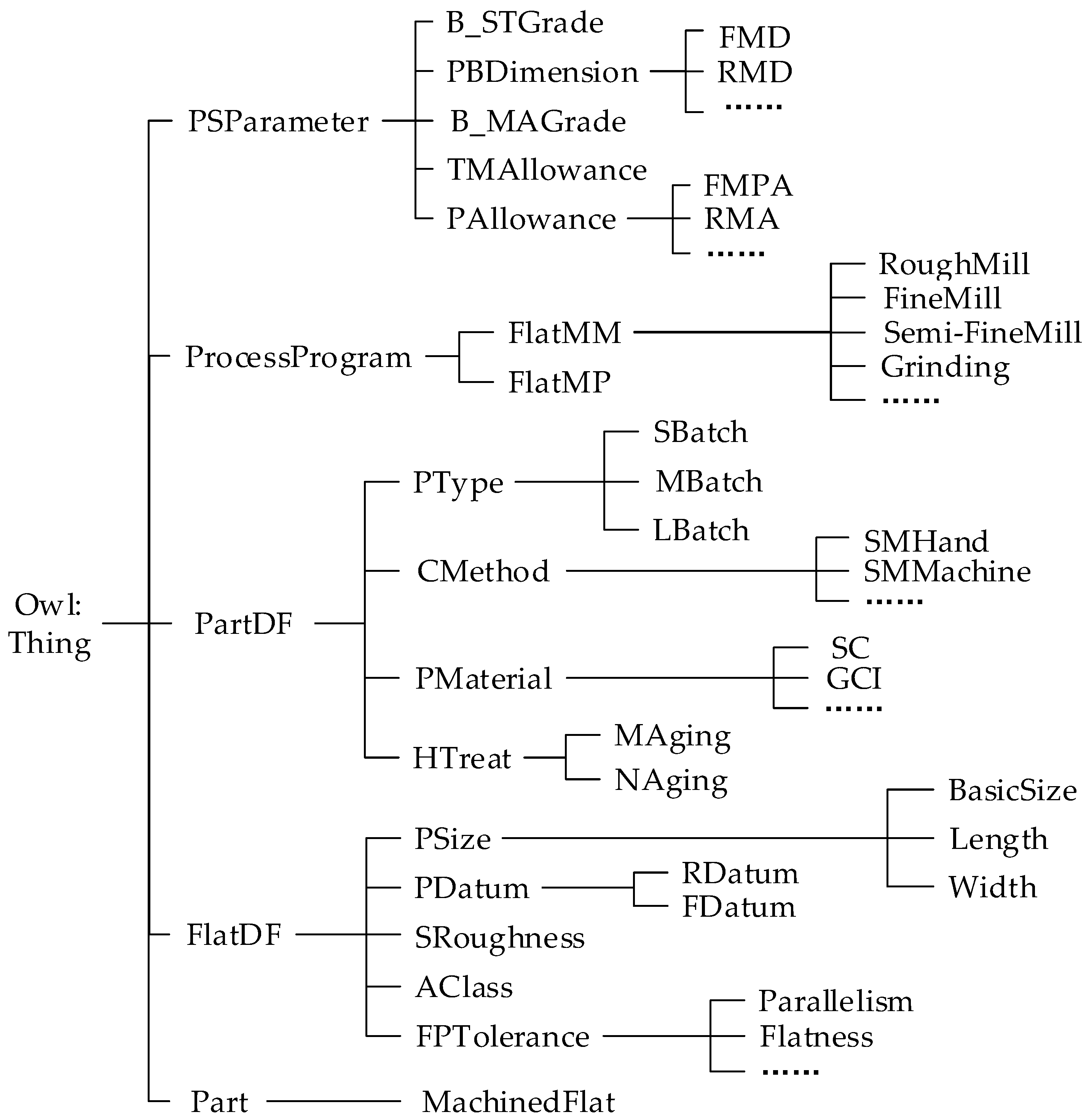
By ontologizing the acquired domain knowledge, an ontology representation model for the domain knowledge of planar machining process decision-making is developed, as illustrated in Figure 6.

Figure 6.
Hierarchy of decision classes for planar machining process of box-type components.
- In the ontology editing tool Protégé, “owl:Thing“ serves as an abstract class and the parent class of all entities. Its subclasses—”Part”, “FlatDF”, “PartDF”, “ProcessProgram” and “PSParameter”—respectively represent box-type parts, design features of the machined surface, design features of the part, machining schemes, and process dimension parameters.
- The subclass “MachineFlat” under “Part” represents the machined surface.
- The subclass “FlatDF” includes “PSize”, “PDatum”, “SRoughness”, “AClass”, and “FPTolerance”, which, respectively, denote nominal dimensions, positioning reference, surface roughness, accuracy class, and geometrical tolerance constraints. The subclass “PSize” further includes “BasicSize”, “Length”, and “Width”, which define the basic size, length, and width of the machined surface. The subclass “PDatum” consists of “FDatum” and “RDatum”, representing finishing datum and rough machining datum, respectively. The subclass “FPTolerance” represents various geometrical tolerances.
- The subclass “PartDF” includes “HTreat”, “PMaterial”, “CMethod”, and “PType”, which correspond to the heat treatment method, part material, casting method, and production type, respectively. These subclasses align with the design features of the part described in Section 3.2.2.
- The subclass “ProcessProgram” contains “FlatMP” and “FlatMM”, which denote machining schemes and machining methods for planar surfaces. The subclass “FlatMM” further categorizes various machining methods, such as rough milling, finish milling, and grinding.
- The subclass “PSParameter” consists of “PAllowance”, “PBDimension”, “TMAllowance”, “B_MAGrade”, and “B_STGrade”, representing machining allowance, process dimensions, total machining allowance, blank machining allowance grade, and blank size tolerance grade, respectively. Additionally, the subclasses “PAllowance” and “PBDimension” specify the allowance and dimensions for each machining operation.
4.3. Definition and Constraint of Attributes
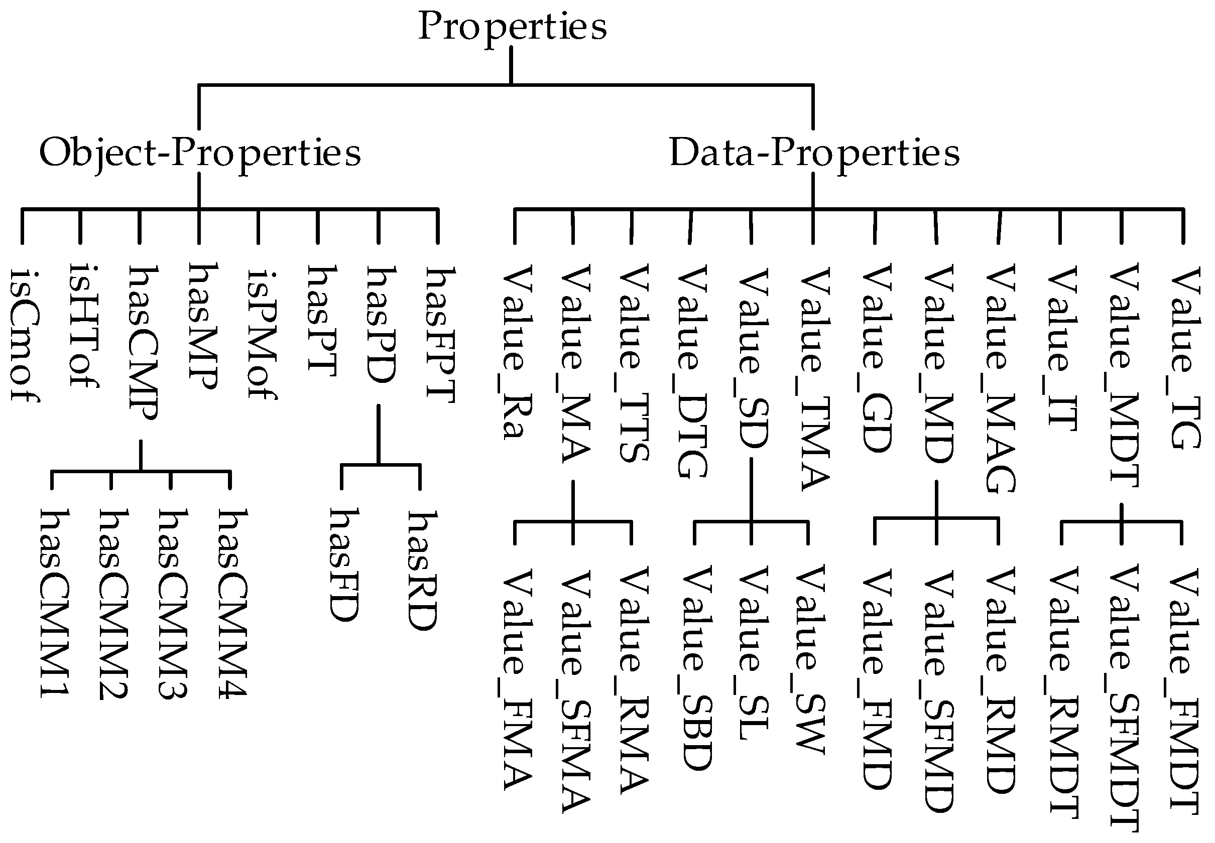
After defining the classes and their hierarchical relationships, it is necessary to define their attributes to describe the relationships between classes as well as between classes and data in the machining process decision-making. These attributes are categorized into two types: object properties and data properties [35]. “Object properties“ represent the relationships between individuals and objects within the classes involved in process decision-making, while “Data properties” describe the intrinsic characteristics of a class through data values, typically including string, Boolean, or numeric types, as illustrated in Figure 7. The domains and ranges of some class attributes are detailed in Table 5.

Figure 7.
Hierarchical relationship between attributes for machining process decision-making.
Table 5.
Domains and Range of some attributes.
The object properties in the ontology model are defined as follows:
“isCMof”, “isHTof”, “isPMof”, and “hasPT” represent the attributes associated with a part’s casting method, heat treatment, material, and production type, respectively. “hasCMP”, “hasFPT”, and “hasPD” denote the attributes of a machined surface, specifically indicating its machining scheme, geometrical tolerance constraints, and positioning reference.
The data properties are defined as follows:
“Value_MAG” and “Value_DTG” specify the numerical values corresponding to the blank machining allowance grade and blank size tolerance grade, respectively. “Value_Ra”, “Value_TG”, “Value_TMA”, “Value_MA”, “Value_SD”, “Value_IT”, and “Value_MDT” define the numerical values associated with surface roughness, geometrical tolerance grade, total machining allowance, process allowance, nominal dimension, accuracy class, and process dimension tolerance, respectively.
5. Planar Machining Process Decision for Box-Type Components
The decision-making process for the planar machining methods and process dimension parameters of box-type components also requires the construction of corresponding rules based on the OWL ontology model. The Semantic Web Rule Language (SWRL) [30] is a rule description language directly applicable to ontologies, and it is independent of any specific reasoning engine. It possesses strong logical expression and intelligent reasoning capabilities. In this study, SWRL is used to construct decision rules for the machining methods and process dimension parameters of box-type components. These rules can be categorized into six types, with some of the rules outlined below; other rules follow a similar structure.
- Rule1-1: Part(?x) ∧ ProductionType(?y) ∧ hasPT(?x,Lb) -> isCMof(?x, SmM)
- Rule1-2: Parts(?x) ∧ isPMof(?x,Gcr) ∧ isCMof(?x,SmM) -> Value_DTG(?x,10) ∧ isMAGof(?x,G)
Rule 1-1 describes the relationship between the production type and the casting method of box-type components. If the production type of the box-type component is large-scale production, the casting method will be sand casting with machine molding. Rule 1-2 specifies the selection of blank parameters. If the material of the box-type component is gray cast iron and the casting method is sand casting with machine molding, the dimensional tolerance level of the blank is CT10, and the machining allowance level is G.
- Rule2-1: Part(?x) ∧ RoughDatum(?y) ∧ hasRD(?x,?y) -> hasRD(?x,Sh)
- Rule2-2: Part(?x) ∧ PType(?y) ∧ hasPT(?x,Lb) -> hasFD(?x,1f2h)
Rules 2-1 and 2-2 describe the selection of the locating datums for the planar machining of box-type components. If the type of production of the box-type part is a large batch, the coarse datum is the main axis hole, and the fine datum is a plane and two holes.
- Rule3-1: Part(?x) ∧ isPMof(?x,Gcr) ∧ isHTof(?x,Na) ∧ MachinedFlat(?y) ∧ Value_Ra(?y,?b) ∧ swrlb:lessThanOrEqual(?b,12.5) ∧ swrlb:greaterThan(?b,3.2) ∧ isITof(?x,11) ∧ hasFPT(?x,PA) ∧ Value_TG(?y,?b) ∧ swrlb:lessThanOrEqual(?b,9) ∧ swrlb:greaterThan(?b,6) -> hasCMP(?y,CMP2) ∧ hasCMM1(?y,Rm) ∧ hasCMM2(?y,SFm)
Rule 3-1 outlines the selection of the machining plan for the box-type component’s planar surface. If the material of the box-type component is gray cast iron, the heat treatment is natural aging, the surface roughness range of the machined faces is between 3.2 and 12.5, the accuracy level is 11, and the geometric constraint is parallelism with a range of 6 to 9, the machining plan for the face will be CMP2, with the machining method consisting of rough milling followed by semi-finish milling.
- Rule4-1: MachinedFlat(?x) ∧ Value_SBD(?x,?v) ∧ swrlb:greaterThan(?v,0) ∧ swrlb:lessThanOrEqual(?v,100) ∧ Part(?y) ∧ isMAGof(?y,G) ∧ Value_DTG(?y,10) -> Value_TMA(?x,3.5)
- Rule4-2: MachinedFlat(?x) ∧ Value_SL(?x,?b) ∧ swrlb:greaterThan(?b,0) ∧ swrlb:lessThanOrEqual(?b,300) ∧ Value_SL(?x,?c)∧swrlb:greaterThan(?c,0) ∧ swrlb:lessThanOrEqual(?c,100) ∧ hasCMP(?x,CMP2) -> Value_SFMA(?x,1.3)
- Rule4-3: MachinedFlat(?x) ∧ hasCMP(?x,CMP1) ∧ Value_TMA(?x,?m) ∧ Value_SFMA(?x,?n) ∧ swrlb:subtract(?t,?m,?n) -> Value_RMA(?x,?t)
Rule 4-1 specifies the total machining allowance for the planar machining of box-type components. If the nominal dimension of the machined face is between 0 and 100mm, the blank dimensional tolerance level is 10, and the machining allowance level is G, the total machining allowance for the face will be 3.5mm. Rules 4-2 and 4-3 describe the machining allowances for individual machining stages. If the dimensions of the machined face are 100x300mm and the machining plan is CMP1, the semi-finish milling allowance will be 1.3mm, and the rough milling allowance will be the total machining allowance minus the semi-finish milling allowance.
- Rule5-1: MachinedFlat(?x) ∧ hasCMP(?x,CMP1) ∧ Value_SBD(?x,?m) -> Value_SFMD(?x,?m)
- Rule5-2: MachinedFlat(?x) ∧ hasCMP(?x,CMP1) ∧ Value_SFMA(?x,?a) ∧ Value_SFMD(?x,?b) ∧ swrlb:add(?m,?a,?b) -> Value_RMD(?x,?m)
Rules 5-1 and 5-2 specify the process dimensions for the planar machining of box-type components. If the machining plan for the planar surface is CMP1, the semi-finish milling process dimension will be the nominal dimension of the planar surface, while the rough milling process dimension will be the semi-finish milling allowance plus the semi-finish milling process dimension.
- Rule6-1: MachinedFlat(?x) ∧ Value_SBD(?x,?v) ∧ swrlb:greaterThan(?v,30) ∧ swrlb:lessThanOrEqual(?v,120) ∧ hasCMP(?x,CMP1) ∧ Part(?y) ∧ isITof(?y,f) -> Value_RMDT(?x,0.3) ∧ Value_SFMDT(?x,0.15)
Rule 6-1 describes the dimensional tolerance for the machining process. If the nominal dimension of the machined face is between 30 and 120 mm, the tolerance grade of the box-type component is 11, and the machining plan is CMP1, the dimensional tolerance for the rough milling process will be 0.3 mm, and the dimensional tolerance for the semi-finish milling process will be 0.15 mm.
6. Implementation and Examples
6.1. Decision-Making Algorithm for Planar Machining Process of Box-Type Components
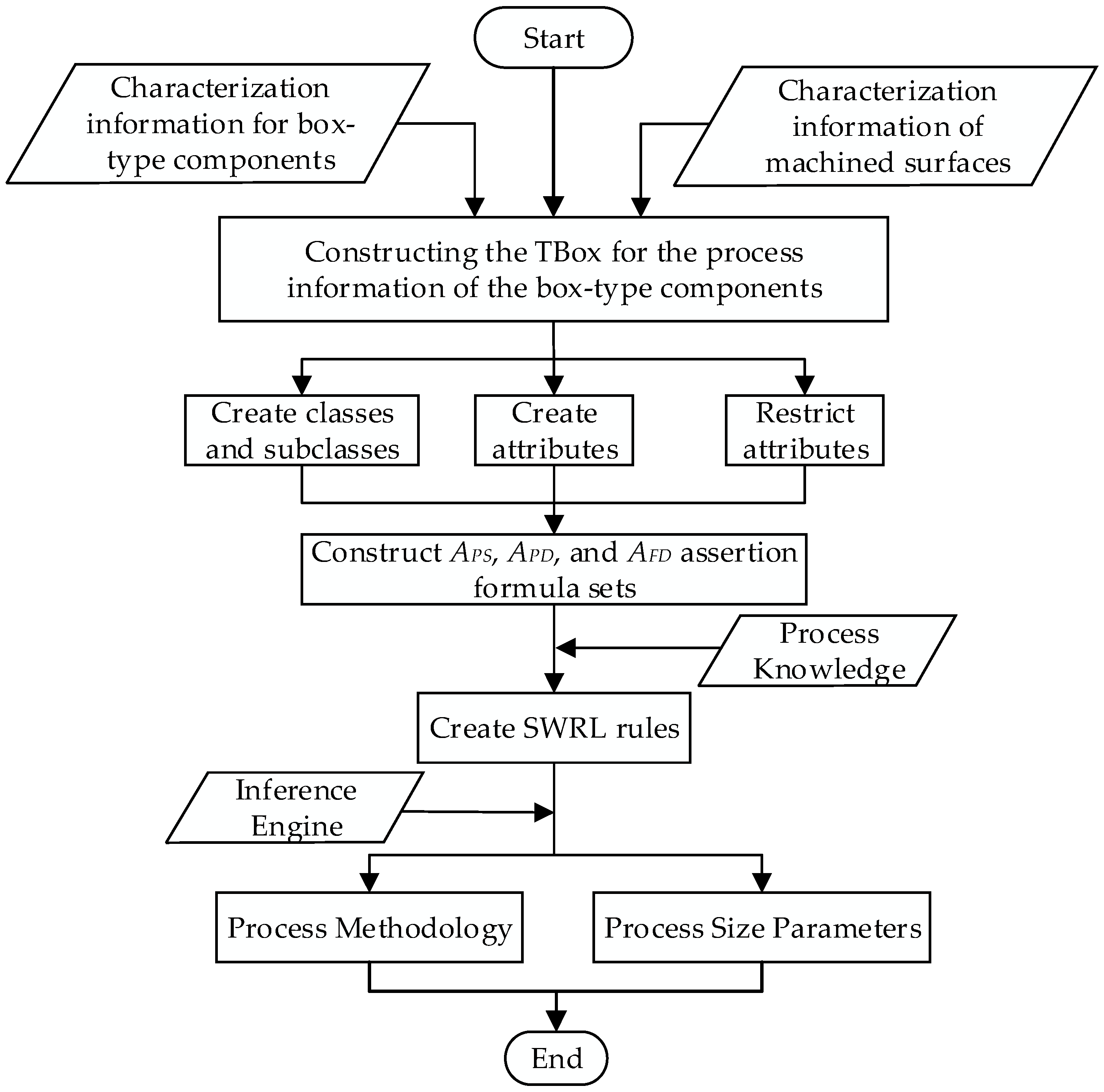
To demonstrate the feasibility of applying ontology theory to address the decision-making process for the planar machining of box components, a feasibility verification algorithm is designed based on the principles of planar machining process decision-making for box components. The detailed steps of the algorithm are shown in Figure 8.
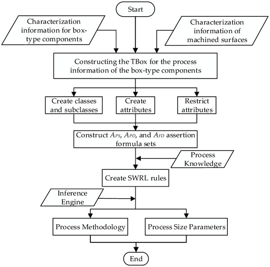
Figure 8.
Algorithm for decision-making on planar machining process of box-type components.
- (1)
- An information-processing TBox for the box-type components is constructed based on the material, production type, dimensions, and geometric tolerances of the box components and their machined faces.
- (2)
- The ontology model for the planar machining process decision-making of box-type components is developed. A hierarchical structure for the process decision classes is established based on the relevant terminology of process knowledge, and attributes are defined and constrained according to the relationships between the classes.
- (3)
- An assertion formula set is constructed. Based on the obtained feature information of the box-type component, assertion formula sets are created for the relationships between the component and its machined faces (APS), the component and its design features (APD), and the machined faces and their design features (AFD).
- (4)
- Based on the constructed assertion formula sets (APS, APD, and AFD) and the SWRL rules for planar machining process decision-making of box-type components, the ontology’s built-in reasoning engine is employed to infer and generate the machining methods and process dimension parameters for the planar machining of the box-type components.
6.2. Case Study
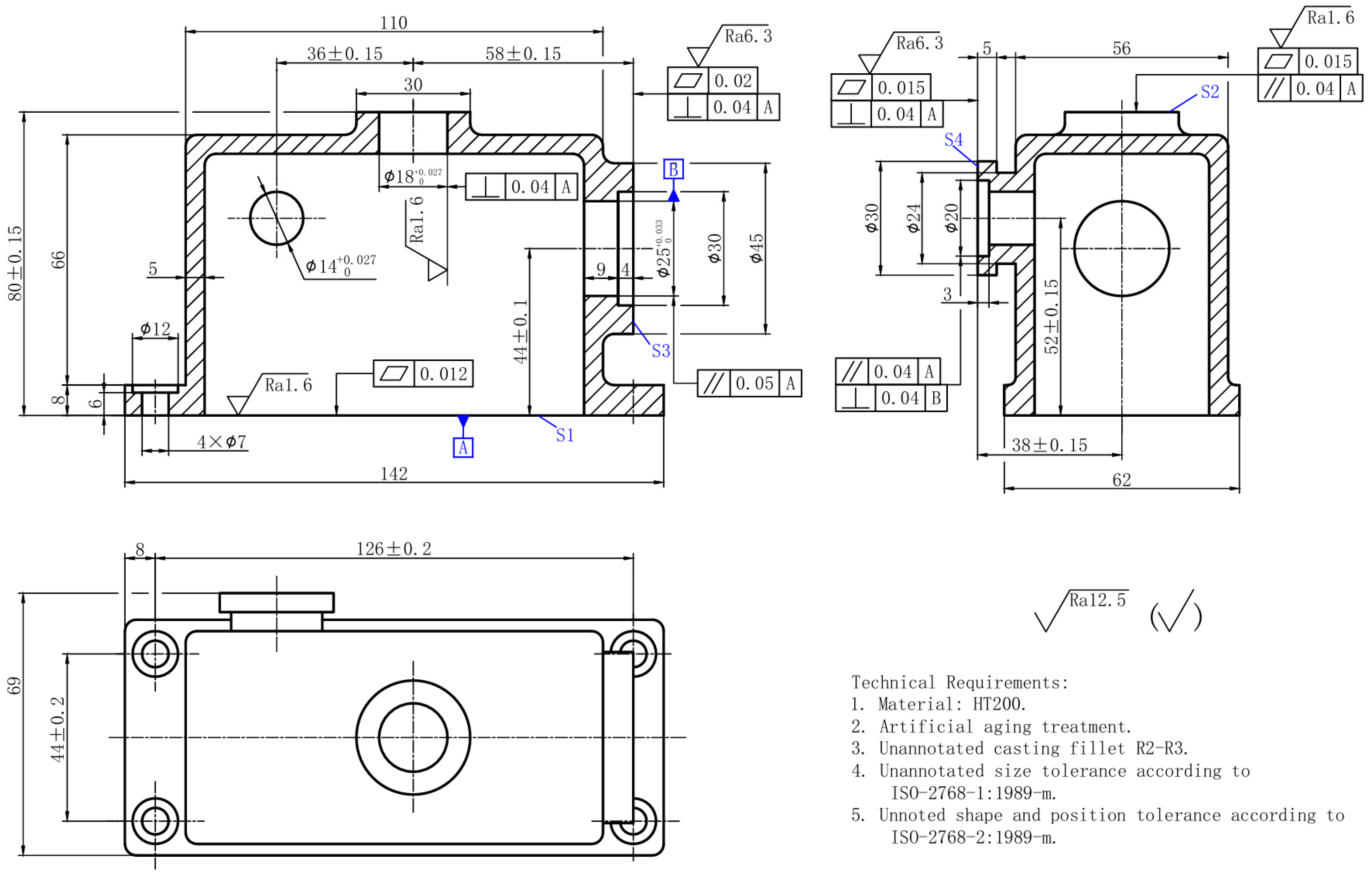
To validate the feasibility of the proposed method for planar machining process decision-making of box-type components, a case study is conducted using a gearbox as an example. The meta-ontology model is created using the ontology editor software Protégé 5.5, with the component diagram shown in Figure 9. The specific steps of the process are outlined below:
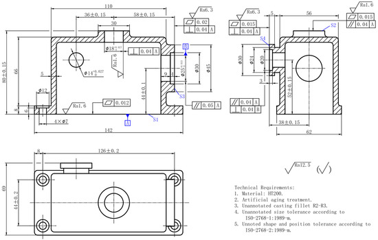
Figure 9.
Gearbox Part Drawing.
- A part model is constructed in the CAD system based on the design information, resulting in four machined faces (S1, S2, S3, and S4) for the box-type component. An assertion formula set (APS) is then constructed to represent the relationship between the part and its machined faces.APS = { MachinedFlat (S1), MachinedFlat (S2), MachinedFlat (S3), MachinedFlat (S4) }
- Extraction of Part-Related Design Feature Information. From Figure 9, the relevant part design feature information can be obtained: the heat treatment applied to the part is aging treatment, the material is HT200, and the production type is mass production. Based on this, an assertion formula set (APD) is constructed to represent the relationships between the part and its associated design features.APD = { Parts (CP), hasPT (Lb), isPMof (Gcr), isHTof (Na), isITof (f) }
- Extraction of Machined Surface-Related Design Feature Information. From Figure 5, the relevant machined surface design feature information can be obtained. Taking surface S1 as an example: basic dimension: 80 mm; length: 142 mm; width: 52 mm; accuracy class: grade 8; surface roughness: 1.6 μm; geometrical tolerance constraint: flatness. Other machined surfaces have similar characteristics. Based on this, an assertion formula set (AFD) is constructed to represent the relationships between the machined surface and its design features.AFD = {Value_Of_Ra (S1, 1.6), Value_Of_Ra (S2, 6.3), Value_Of_Ra (S3, 0.8), Value_Of_Ra (S4, 6.3), Value_Of_SBD (S1, 80), Value_Of_SBD (S2, 80), Value_Of_SBD (S3, 58), Value_Of_SBD (S4, 38), Value_SL (S1, 142), Value_SL (S2, 30), Value_SL (S3, 45), Value_SL (S4, 30), Value_SW (S1, 69), Value_SW (S2, 30), Value_SW (S3, 45), Value_SW (S4, 30), hasFPT(S1,FN), hasFPT(S2,PA), hasFPT (S3,SQ), hasFPT (S4,SQ), Value_TG(S1, 7), Value_ TG (S2, 8), Value_ TG (S3, 11), Value_ TG (S4, 11) }
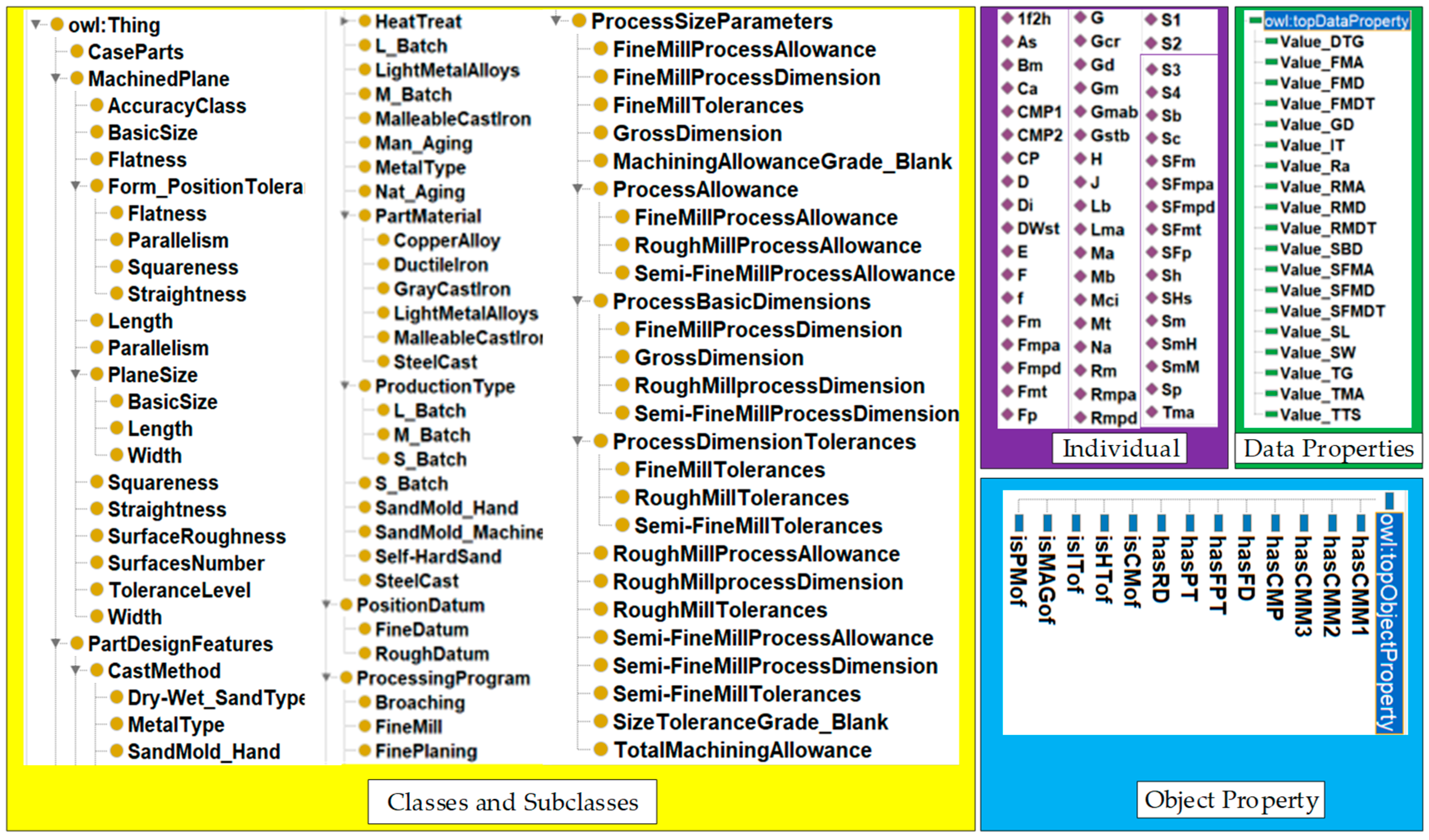
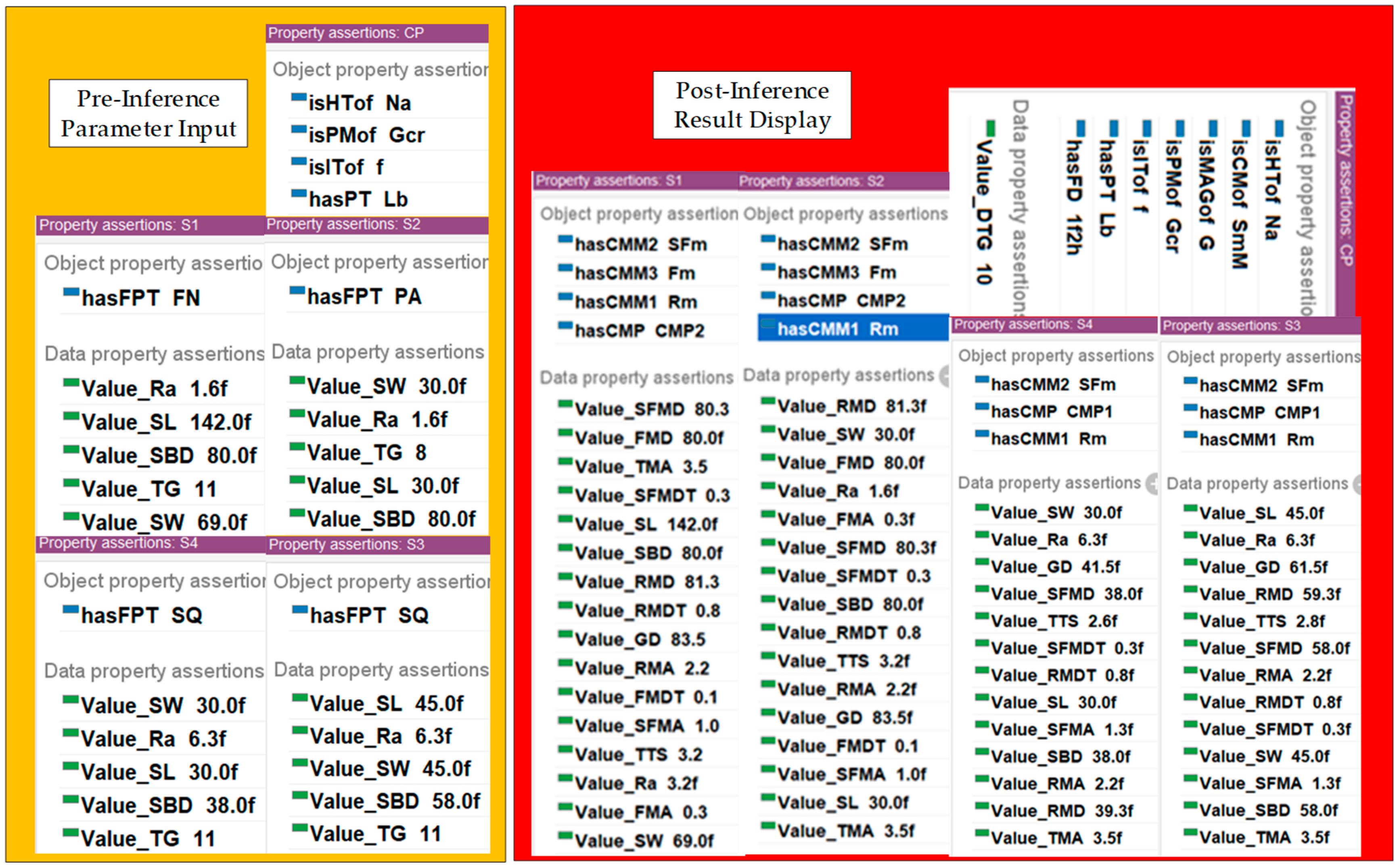
- The machining process information, machining scheme for the machined surface, and process dimension parameters for box-type parts are determined based on key attributes such as material, heat treatment, production type, and the machined surface characteristics, including dimensions, accuracy class, and geometrical tolerances. Utilizing this information, an ontology-based planar machining process model for box-type parts is developed, as illustrated in Figure 10. By constructing SWRL inference rules and integrating the assertion formula sets APS, APD, and AFD, the machining process information, machining scheme for the machined surface, and process dimension parameters are inferred, as shown in Figure 11. The results are systematically organized and presented in Table 6, Table 7 and Table 8. The inferred results align with those obtained using traditional methods, such as consulting relevant international standards and manual calculations [32,36].
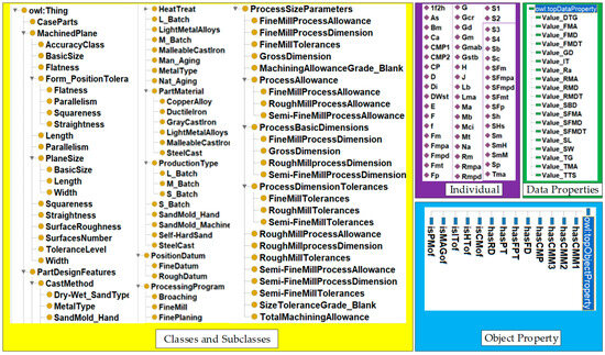 Figure 10. Meta-ontology model for decision-making for planar machining process of gearbox.
 Figure 11. Decision-making results of planar machining process for gearboxes.
Table 6. Gearbox machining process information.
Table 7. Positioning datums for gearbox machining.
Table 8. Machining plan and process size parameters of the machined surface.
Figure 11. Decision-making results of planar machining process for gearboxes.
Table 6. Gearbox machining process information.
Table 7. Positioning datums for gearbox machining.
Table 8. Machining plan and process size parameters of the machined surface.
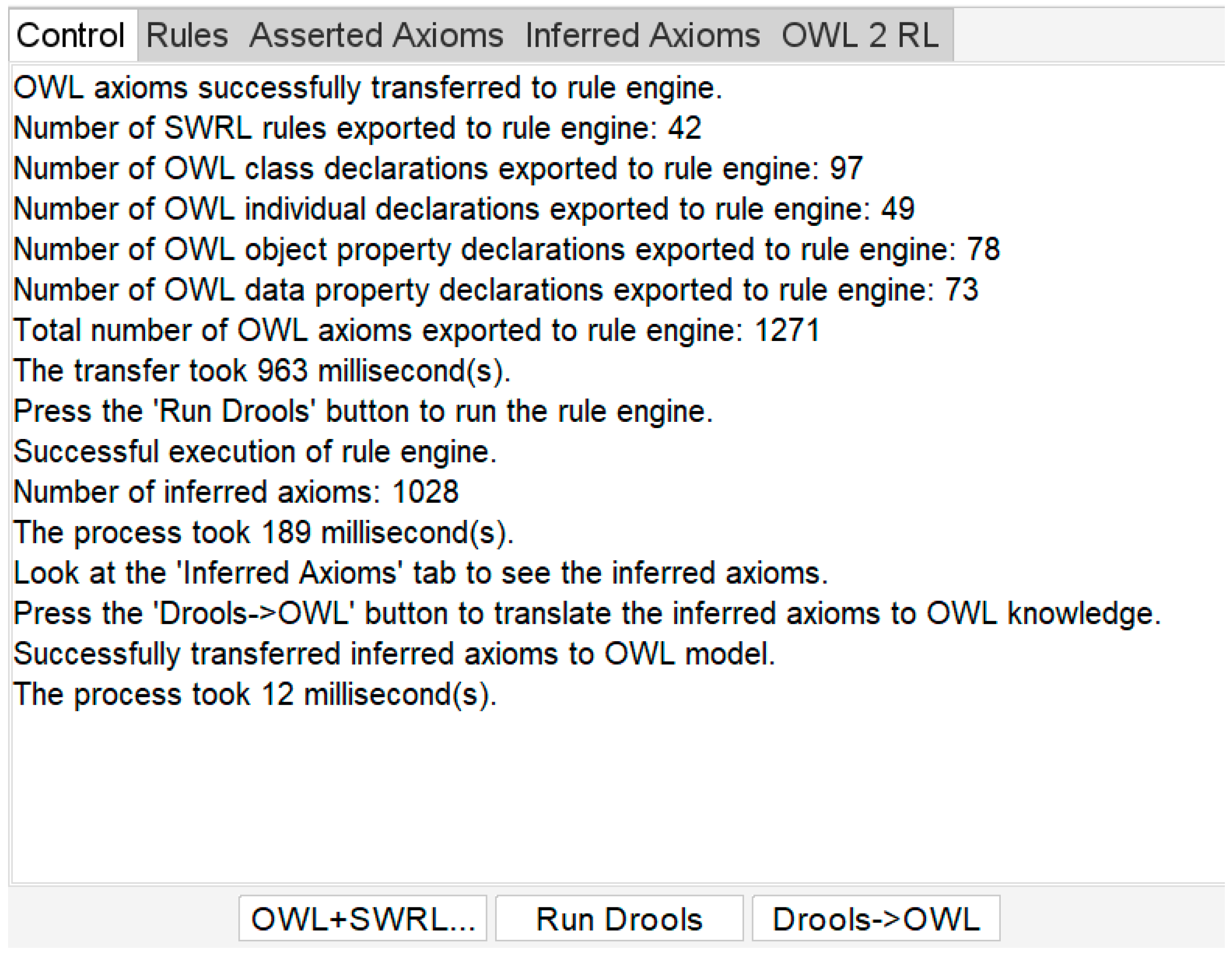
Furthermore, the time consumption at various stages of the inference process is depicted in Figure 12. Transmitting the OWL assertion formula set (ABox) and the SWRL rule base to the ontology rule engine took 963 ms. Executing the inference process within the reasoning engine required 189 ms. Converting the inference results into OWL only took 12 ms.
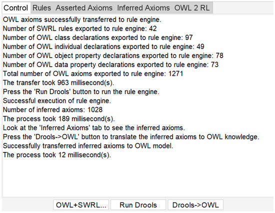
Figure 12.
Time spent on the reasoning process.
These results demonstrate that the proposed ontology-based decision-making method for the planar machining process of box-type parts offers significant advantages in computational efficiency and feasibility.
7. Discussion
This paper presents an ontology-based decision-making method for the planar machining process of box-type parts. A hierarchical information representation model is constructed to describe the various concepts and their interrelationships in the process design of box-type parts. Based on this model, an ontology-based decision-making model for planar machining processes is developed. This model, when combined with SWRL (Semantic Web Rule Language) inference rules, can automatically generate the machining plans and process parameters for box-type parts. This section compares the proposed method with the ontology-based method for automatic generation of dimensional parameters for external cylindrical operations of shaft-type parts, as described in Section 2.
From the perspective of process design, the method proposed in this paper addresses the machining process design for box-type parts. By leveraging the advantages of ontologies, the method successfully enables decision-making for the planar machining process and process parameters for box-type parts, thereby filling the gap in the application of ontology technology in the process design of such parts. Additionally, the method for automatic generation of dimensional parameters for external cylindrical operations of shaft-type parts, proposed in [23], does not consider factors such as blank characteristics, economic accuracy, and geometric tolerance constraints, which could potentially affect the final process design. In contrast, the proposed method in this paper takes into account more factors influencing the process design results in the machining decision-making process for box-type parts. Consequently, the resulting machining plans and process parameters are more aligned with engineering and technical requirements.
From the perspective of validation through examples, the proposed method demonstrates the effectiveness of using ontology-based reasoning mechanisms to derive machining plans and process parameters for box-type parts. Compared to the research in [23], which focuses on shaft-type parts, the mechanical parts addressed in this paper (box-type parts) are more complex, and the derived process parameters are more comprehensive. For instance, the method takes into account parameters related to blank characteristics, casting processes, and the selection of positioning datums during machining, providing a more thorough and applicable solution for process decision-making.
8. Conclusion and Future Work
To address the challenge of intelligent decision-making in the planar machining process of box-type parts, this study proposes an ontology-based intelligent decision-making method. A hierarchical information representation model for the planar machining process of box-type parts is constructed, which is then formalized into an ontology using OWL (Web Ontology Language). Based on domain-specific knowledge and expertise involved in machining process decision-making, SWRL (Semantic Web Rule Language) rules are formulated to establish inference rules. The reasoning engine embedded in Protégé 5.5 is employed to automatically generate the machining methods and process parameters for box-type parts. This method requires only the necessary process information of the box-type part as input, enabling the automatic generation of machining methods and process parameters while minimizing human intervention. As a result, the accuracy of decision-making is improved, and the reliance on manual expertise is reduced, enhancing decision-making efficiency in the machining process.
By utilizing OWL and SWRL for the formalized representation of planar machining process knowledge, this study leverages their advantages in knowledge representation to reduce the difficulty of computer-based interpretation, understanding, and reasoning of design information and related machining knowledge. This approach facilitates a standardized representation and exchange of process design information across CAX (Computer-Aided Technologies) systems, thereby promoting knowledge sharing and interoperability among heterogeneous CAX systems.
However, this study focuses exclusively on the planar machining process of box-type parts under the assumption that the design datum and positioning datum coincide. In actual machining scenarios, additional factors such as holes, slots, and non-coinciding datums must be considered. Moreover, the current approach does not account for machining environment and equipment constraints in process decision-making.
Future research will aim to expand and refine the machining process knowledge base by incorporating additional machining features and process constraints. This will enhance the accuracy and applicability of machining process decision-making. Additionally, an ontology-based decision-making software for the machining process of box-type parts will be developed and integrated with mainstream CAX systems, further advancing intelligent and automated machining process planning.
Author Contributions
Conceptualization, Z.S. and M.H.; methodology, Z.S. and M.H.; validation, Z.S., Z.T. and M.H.; formal analysis, Z.T.; investigation, Z.S.; resources, Z.H.; data curation, W.H.; writing—original draft preparation, Z.S.; writing—review and editing, Z.S., M.H. and Z.T.; visualization, Z.T.; supervision, W.H.; project administration, Z.H.; funding acquisition, M.H. and Z.S. All authors have read and agreed to the published version of the manuscript.
Funding
This research was funded by the National Natural Science Foundation of China (No. 52165064) and funded by Professor Meifa Huang.
Institutional Review Board Statement
Not applicable.
Informed Consent Statement
Not applicable.
Data Availability Statement
Data are contained within the article.
Acknowledgments
We would like to acknowledge Meifa Huang and Zhemin Tang for their guidance, revisions and help in writing the manuscript, and Zecheng Hu and WeiHao Hu for providing technical information for writing the paper and proofreading the paper.
Conflicts of Interest
The authors declare no conflicts of interest.
References
- Su, Y.; Chu, X.; Chen, D.; Sun, X. A Genetic Algorithm for Operation Sequencing in CAPP Using Edge Selection Based Encoding Strategy. J. Intell. Manuf. 2018, 29, 313–332. [Google Scholar] [CrossRef]
- Liu, J.; Zhou, H.; Tian, G.; Liu, X.; Jing, X. Digital Twin-Based Process Reuse and Evaluation Approach for Smart Process Planning. Int. J. Adv. Manuf. Technol. 2019, 100, 1619–1634. [Google Scholar] [CrossRef]
- Deja, M.; Siemiatkowski, M.S. Machining Process Sequencing and Machine Assignment in Generative Feature-Based CAPP for Mill-Turn Parts. J. Manuf. Syst. 2018, 48, 49–62. [Google Scholar] [CrossRef]
- Duan, J.; Duan, Y. Toward a Framework of Extracting Typical Machining Process Routines Based on Knowledge Representation Learning. Adv. Eng. Inform. 2024, 60, 102431. [Google Scholar] [CrossRef]
- Leo Kumar, S.P.; Jerald, J.; Kumanan, S. An Intelligent Process Planning System for Micro Turn-Mill Parts. Int. J. Prod. Res. 2014, 52, 6052–6075. [Google Scholar] [CrossRef]
- Leo Kumar, S.P.; Jerald, J.; Kumanan, S. Feature-Based Modelling and Process Parameters Selection in a CAPP System for Prismatic Micro Parts. Int. J. Comput. Integr. Manuf. 2014, 28, 1046–1062. [Google Scholar] [CrossRef]
- Zai, D. Research on Key Technology of Feature-Based Three-Dimensional Process Design of Box-Like Parts. Master’s Thesis, Beijing Institute of Technology, Beijing, China, 2015. [Google Scholar]
- Zhu, H.; Li, J. Research on Three-Dimensional Digital Process Planning Based on MBD. Kybernetes 2018, 47, 816–830. [Google Scholar] [CrossRef]
- Wang, T.; Fang, L. Research on the Construction of Topological Ontology Model for Complex Mechanical Products. J. Mech. Electr. Eng. 2020, 37, 1121–1143. [Google Scholar]
- Zhao, Z.; Zhong, Y. Ontology construction and reasoning for product customization. J. Guilin Univ. Electron. Technol. 2017, 37, 483–489. [Google Scholar] [CrossRef]
- Rehage, G. Ontologie-Basiertes WBS Für Die Arbeitsplanung: Intelligente Wissensverwaltung Und Maschinenauswahl. In Intelligente Arbeitsvorbereitung auf Basis Virtueller Werkzeugmaschinen; Springer: Berlin/Heidelberg, Germany, 2019; pp. 41–90. [Google Scholar]
- Höfermann, H. Semantische Integration Der Disziplinübergreifenden Und Der Disziplinspezifischen Ebene in Der Entwicklung Intelligenter Technischer Systeme. In Tag des Systems Engineering 2024: Tagungsband Leipzig, 13.-15. November 2024; Gesellschaft fuer Systems Engineering: Bremen, Germany, 2024; Volume 22, p. 339. [Google Scholar]
- Podkolodnyy, N.; Podkolodnaya, O. Ontologies in Bioinformatics and Systems Biology. Russ. J. Genet. Appl. Res. 2016, 6, 749–758. [Google Scholar] [CrossRef]
- Manzoor, S.; Rocha, Y.G.; Joo, S.-H.; Bae, S.-H.; Kim, E.-J.; Joo, K.-J.; Kuc, T.-Y. Ontology-Based Knowledge Representation in Robotic Systems: A Survey Oriented toward Applications. Appl. Sci. 2021, 11, 4324. [Google Scholar] [CrossRef]
- Koper, R. Current Research in Learning Design. J. Educ. Technol. Soc. 2006, 9, 13–22. [Google Scholar]
- Liu, H.; Du, J. Semantic Modeling of Manufacturing Domain Knowledge Based on Multidimensional Ontology. Manuf. Technol. Mach. Tools 2019, 9, 140–146. [Google Scholar]
- Zhong, Y.; Lu, H. Construction of a Comprehensive Domain Ontology Knowledge Base for Assembly Tolerance. Comput. Eng. Sci. 2016, 38, 1413. [Google Scholar]
- Yu, M.; Tianlong, G.; Liang, C.; Fengying, L. Assembly Ontology for Assembly Sequence Planning. Int. J. Pattern Recognit. Artif. Intell. 2016, 29, 203–215. [Google Scholar]
- Chen, S.; Yi, J.; Jiang, H.; Zhu, X. Ontology and CBR Based Automated Decision-Making Method for the Disassembly of Mechanical Products. Adv. Eng. Inform. 2016, 30, 564–584. [Google Scholar]
- Peng, Z.; Huang, M.; Zhong, Y.; Tang, Z. Construction of Ontology for Auto-Interpretable Tolerance Semantics in Skin Model. J. Ambient. Intell. Humaniz. Comput. 2020, 11, 3545–3558. [Google Scholar] [CrossRef]
- Shi, X.; Tian, X.; Wang, G.; Zhang, M.; Zhao, D. A Simplified Model for Assembly Precision Information of Complex Products Based on Tolerance Semantic Relations. Sustainability 2018, 10, 4482. [Google Scholar] [CrossRef]
- He, Y.; Hao, C.; Wang, Y.; Li, Y.; Wang, Y.; Huang, L.; Tian, X. An Ontology-Based Method of Knowledge Modelling for Remanufacturing Process Planning. J. Clean. Prod. 2020, 258, 120952. [Google Scholar] [CrossRef]
- Wang, J.; Huang, M. Ontology-Based Method for Automatic Generation of Dimensional Parameters of Cylindrical Process for Shaft Parts. J. Guilin Univ. Electron. Sci. Technol. 2022, 42, 468–475. [Google Scholar]
- Zhang, C. A Study of Formal Description and Retrieval of Artifacts Based on Domain Ontology. Master’s Thesis, Kunming University of Science and Technology, Kunming, China, 2018. [Google Scholar]
- Horrocks, I.; Kutz, O.; Sattler, U. The Even More Irresistible SROIQ. Kr 2006, 6, 57–67. [Google Scholar]
- Li, Y.; Zhang, Z. Research on Domain Ontology Construction Method. Comput. Eng. Sci. 2008, 30, 129. [Google Scholar]
- Fernández-López, M.; Gómez-Pérez, A. Overview and Analysis of Methodologies for Building Ontologies. Knowl. Eng. Rev. 2002, 17, 129–156. [Google Scholar] [CrossRef]
- Youn, S.; McLeod, D. Ontology Development Tools for Ontology-Based Knowledge Management. In Encyclopedia of E-Commerce, E-Government, and Mobile Commerce; IGI Global: Hershey, PA, USA, 2006; pp. 858–864. [Google Scholar]
- Fraga, A.L.; Vegetti, M.; Leone, H.P. Ontology-Based Solutions for Interoperability among Product Lifecycle Management Systems: A Systematic Literature Review. J. Ind. Inf. Integr. 2020, 20, 100176. [Google Scholar]
- Horrocks, I.; Patel-Schneider, P.F.; Boley, H.; Tabet, S.; Grosof, B.; Dean, M. SWRL: A Semantic Web Rule Language Combining OWL and RuleML. W3C Memb. Submiss. 2004, 21, 1–31. [Google Scholar]
- Ji, Z. Analyzing the Principle of Machining Process Design of Parts. Ind. Des. 2015, 117. [Google Scholar]
- Chen, H. Handbook of Practical Machining Processes, 4th ed.; Machinery Industry Press: Beijing, China, 2016. [Google Scholar]
- Song, F. Design method of plane blank size basedon reference vector. Master’s Thesis, Taiyuan University of Technology, Taiyuan, China, 2018. [Google Scholar]
- Qin, Y.; Jiang, C.; Huana, M. Automatic Generation of Assembly Sequence Based on Ontology. Comput. Integr. Manuf. Syst. 2018, 24, 1345. [Google Scholar]
- Bravo, M.; Hoyos Reyes, L.F.; Reyes Ortiz, J.A. Methodology for Ontology Design and Construction. Contaduría Y Adm. 2019, 64, 134. [Google Scholar] [CrossRef]
- Zhang, B. Typical Precision Parts Machining Process Analysis and Examples; Mechanical Industry Press: Beijing, China, 2017. [Google Scholar]

Disclaimer/Publisher’s Note: The statements, opinions and data contained in all publications are solely those of the individual author(s) and contributor(s) and not of MDPI and/or the editor(s). MDPI and/or the editor(s) disclaim responsibility for any injury to people or property resulting from any ideas, methods, instructions or products referred to in the content. |
© 2025 by the authors. Licensee MDPI, Basel, Switzerland. This article is an open access article distributed under the terms and conditions of the Creative Commons Attribution (CC BY) license (https://creativecommons.org/licenses/by/4.0/).