
Sizing the Split DC Link Capacitance in Three-Phase Three-Level Bidirectional AC-DC Converters Operating with Arbitrary Power Factor Under Zero-Sequence Injection Restriction


 ,
,  and
and 
Abstract
1. Introduction
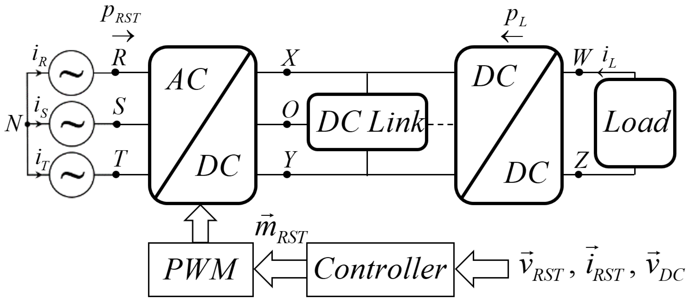
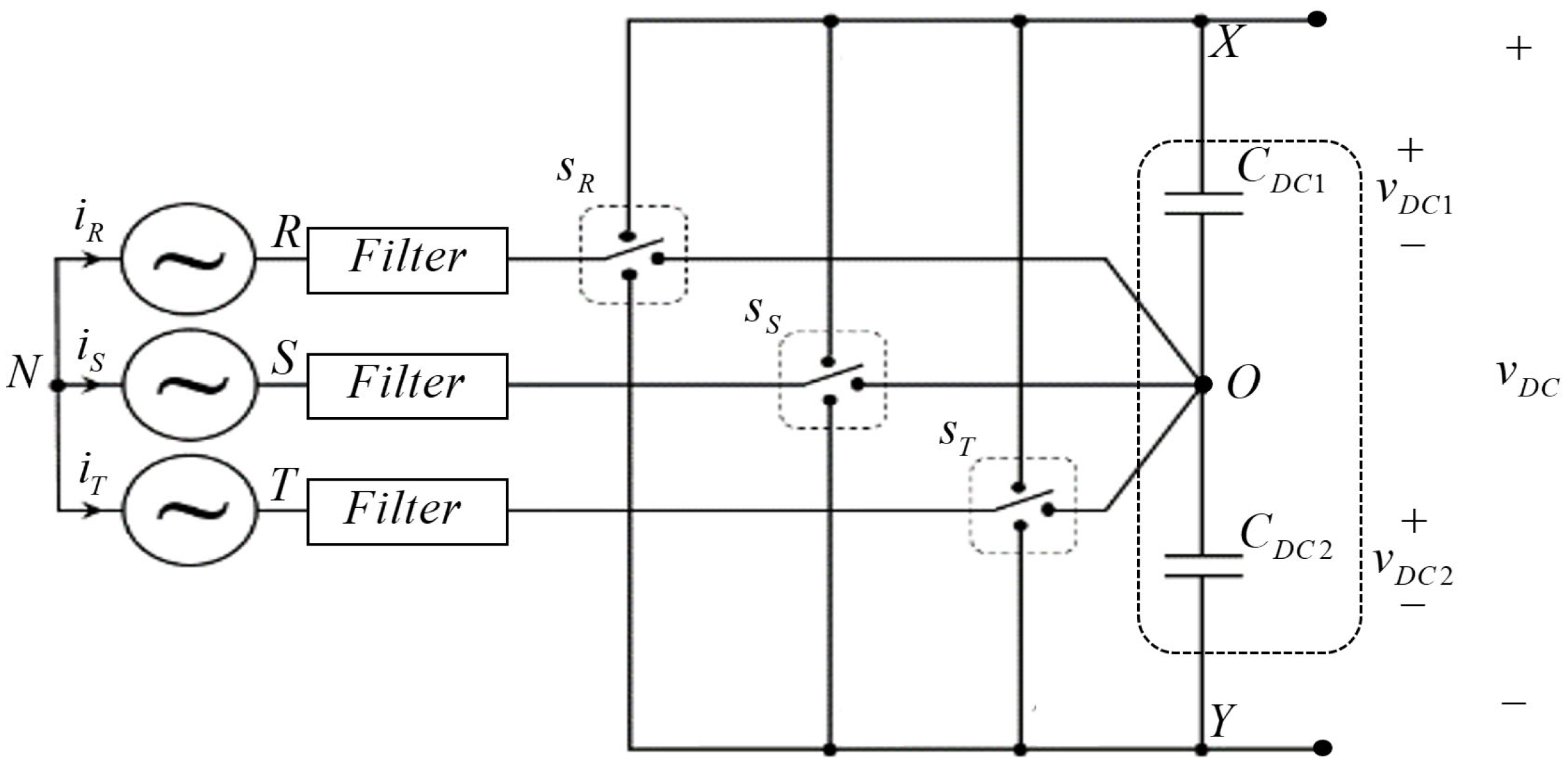
2. Split DC Link Voltages in Zero-Sequence-Restricted Three-Phase Three-Level AC-DC Converter
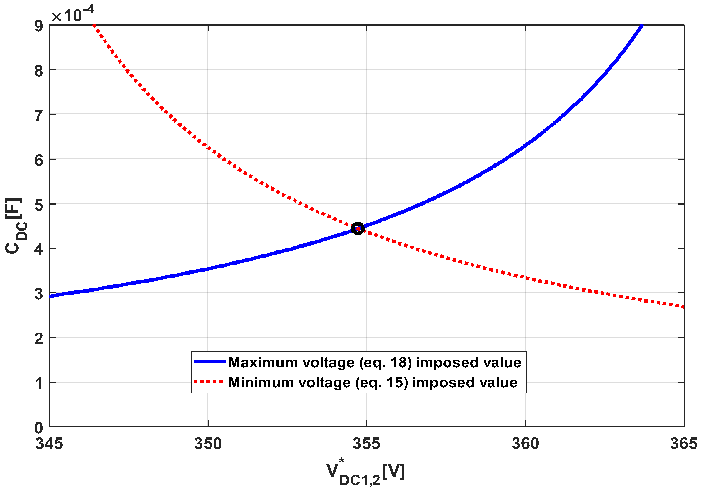
3. DC Link Capacitance Sizing
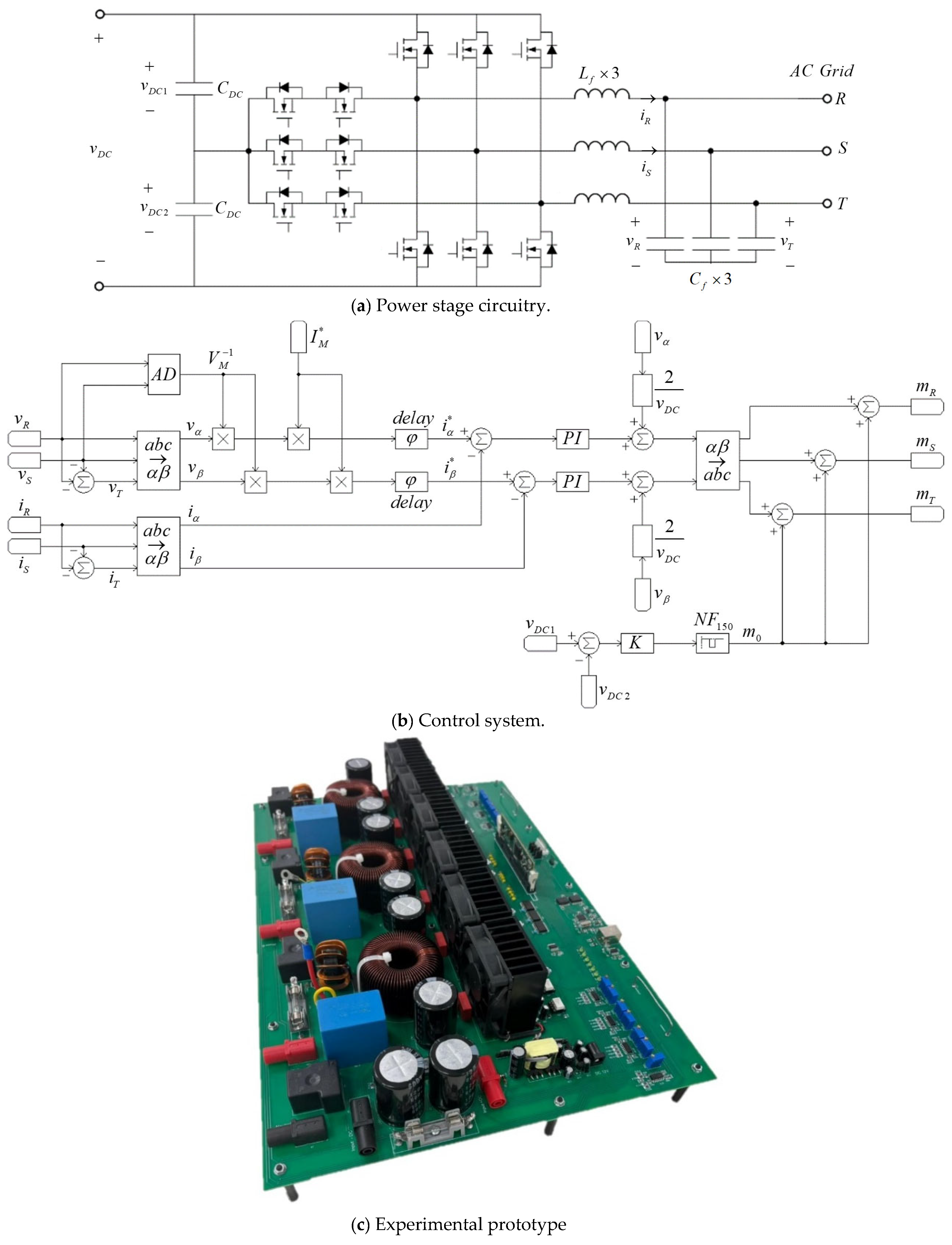
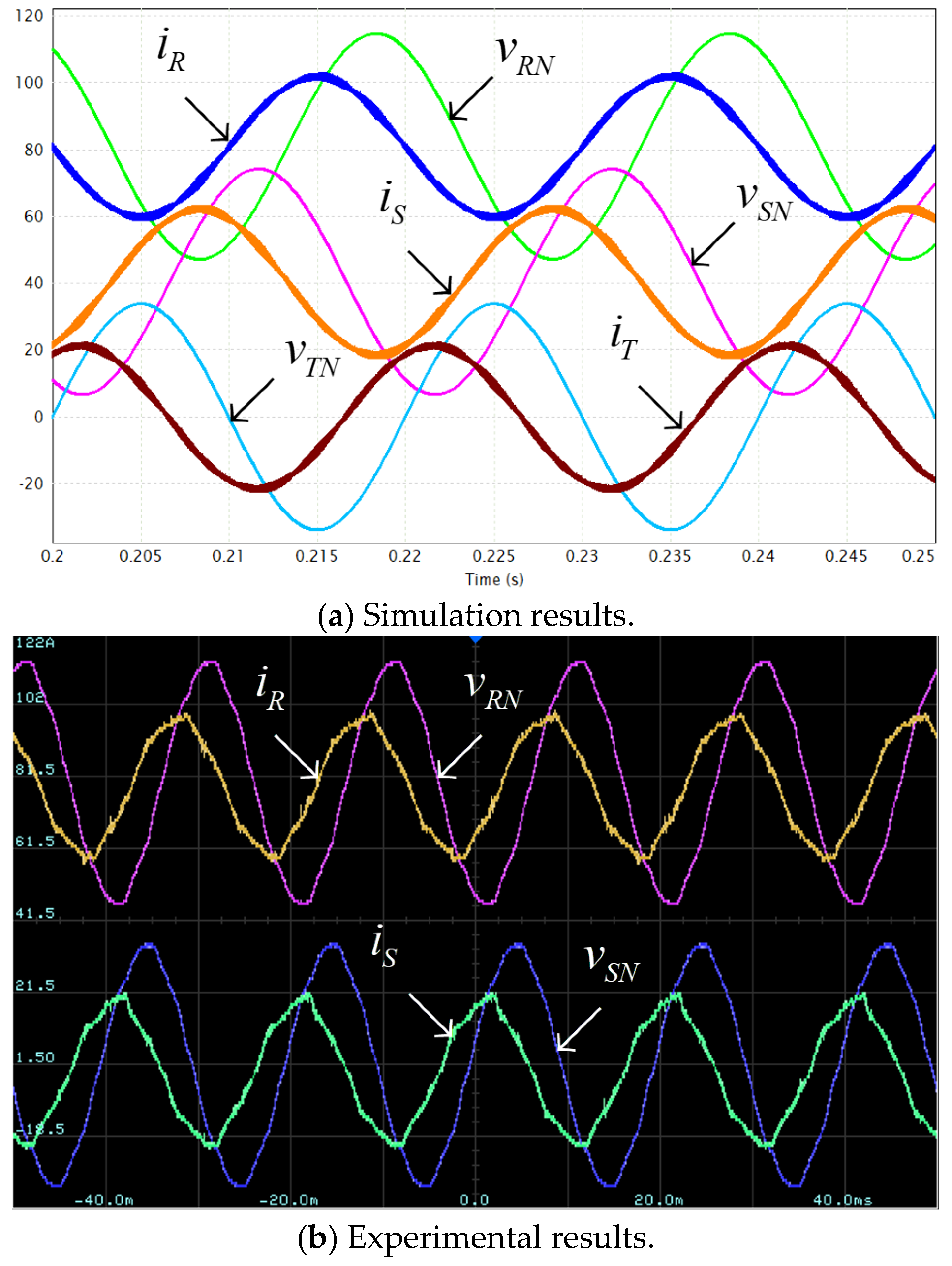
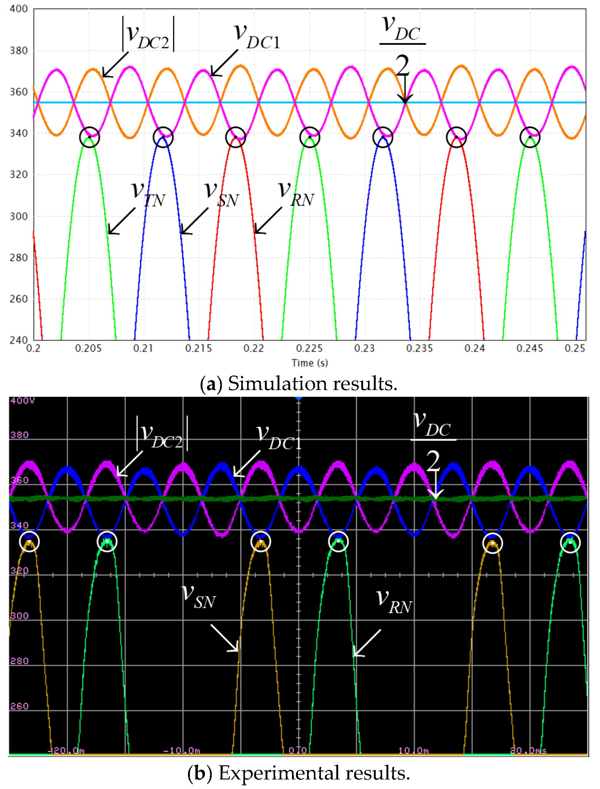
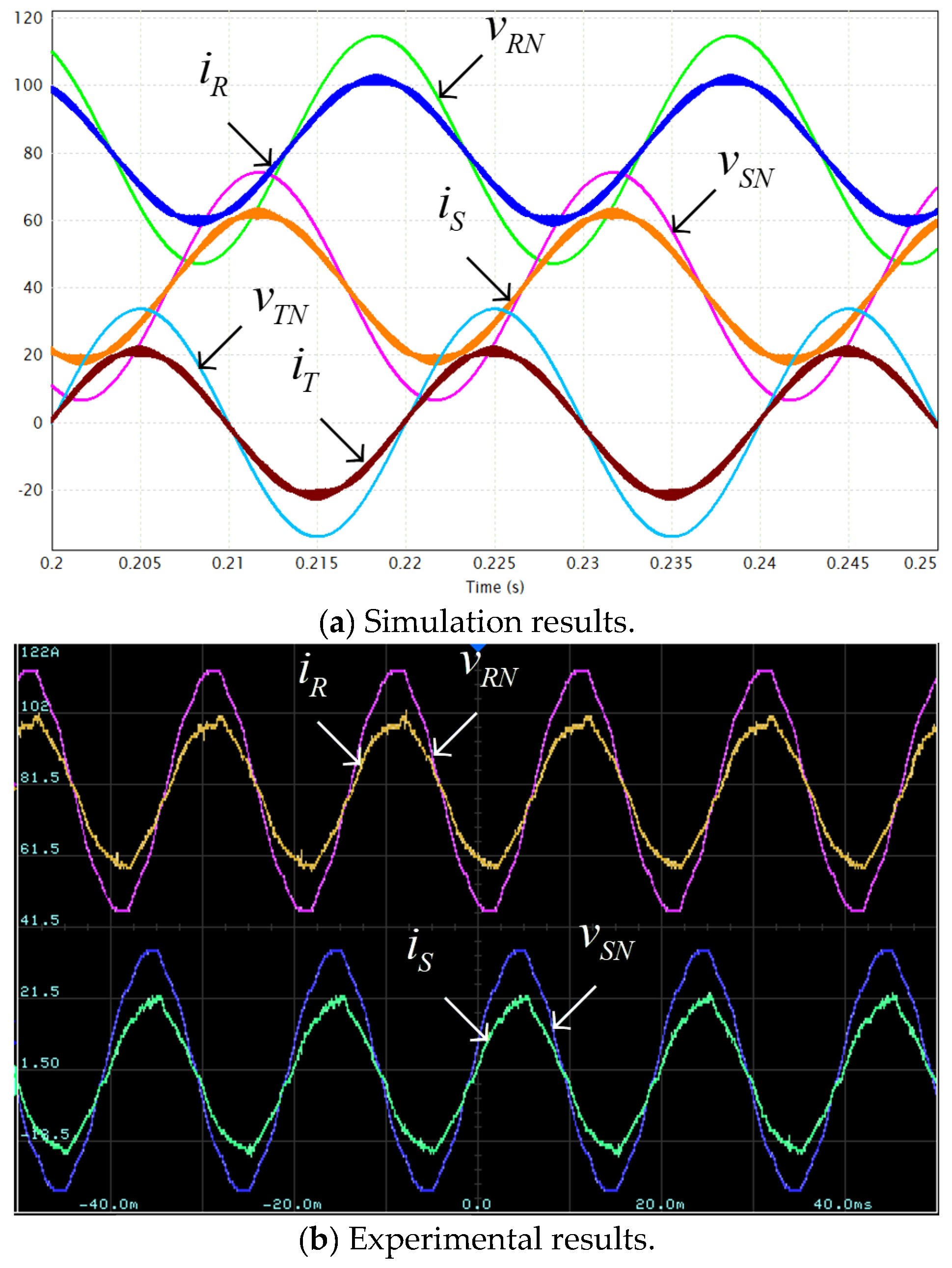
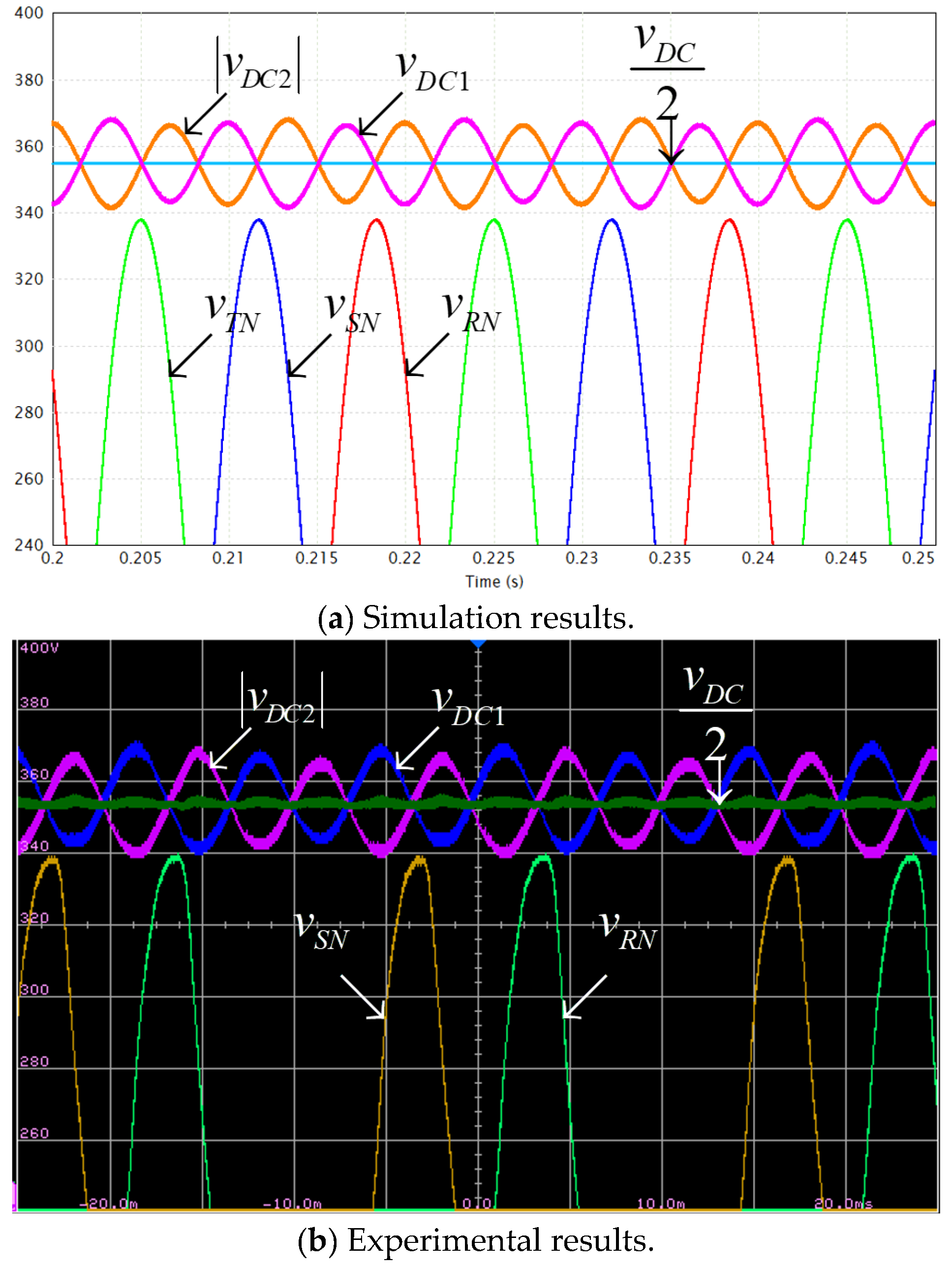
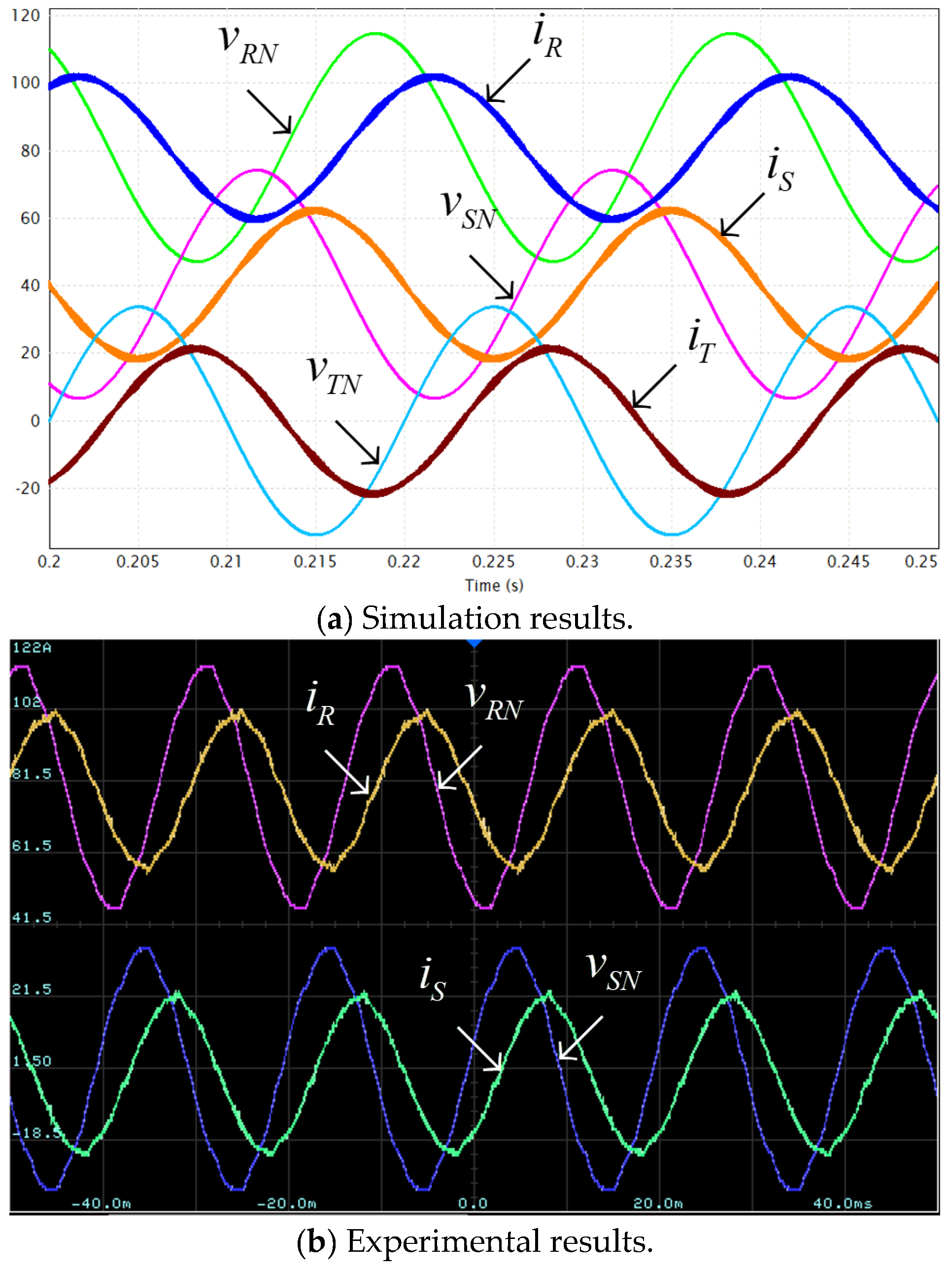
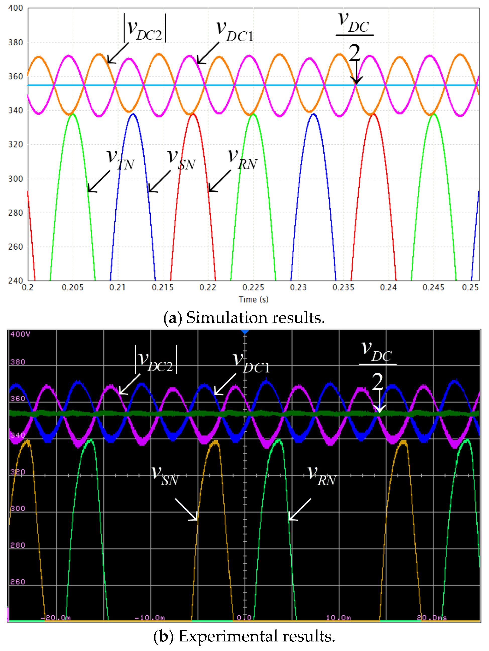
4. Validation
5. Conclusions
Author Contributions
Funding
Data Availability Statement
Conflicts of Interest
Nomenclature
| vector of grid voltages | |
| grid voltages magnitude | |
| currents vector angle With Respect To. voltages vector angle | |
| vector of grid currents | |
| grid currents magnitude | |
| power factor | |
| total apparent power | |
| vector of modulation indices | |
| modulation indices magnitude | |
| zero-sequence modulation component | |
| vector of partial DC link voltages | |
| individual partial DC link voltages | |
| instantaneous AC-side phase power vector | |
| total instantaneous AC-side power | |
| vector of converter imposed AC-side voltages | |
| DC link voltage reference value | |
| split DC link set point voltages | |
| split DC link capacitances |
References
- Bose, B.K. Multi-Level Converters. Electronics 2015, 4, 582–585. [Google Scholar] [CrossRef]
- Franquelo, L.G.; Leonand, J.; Rodriguez, J. The age of multilevel converters arrives. IEEE Ind. Electron. Mag. 2008, 2, 28–39. [Google Scholar] [CrossRef]
- Rodriguez, J.; Lai, J.-S.; Peng, F.Z. Multilevel inverters: A survey of topologies, controls, and applications. IEEE Trans. Ind. Electron. 2002, 49, 724–738. [Google Scholar] [CrossRef]
- Norões, M.; Jacobina, C.B.; Carlos, G.A. A new three-phase ac–dc–ac multilevel converter based on cascaded three-leg converters. IEEE Trans. Ind. Appl. 2017, 53, 2210–2221. [Google Scholar]
- Zhou, D.; Zhao, J.; Li, Y. Model-predictive control scheme of five-leg ac–dc–ac converter-fed induction motor drive. IEEE Trans. Ind. Electron. 2016, 63, 4517–4526. [Google Scholar] [CrossRef]
- Lima, M.; Cursino, B.J.; Rocha, N.; Santos, E.C. Ac–dc–ac three-phase converter based on three three-leg converters connected in series. IEEE Trans. Ind. Appl. 2016, 52, 3171–3181. [Google Scholar]
- Filho, S.; Cipriano, O.; de Almeida, B.R.; Souza, D.; Fernandes Neto, T.R. High-frequency isolated AC–DC–AC interleaved converter for power quality applications. IEEE Trans. Ind. Appl. 2018, 54, 4594–4602. [Google Scholar] [CrossRef]
- Norões, M.; Jacobina, C.B.; Freitas, N.B.; Queiroz, A.; Cabral Silva, E.R. Three-phase four-wire ac–dc–ac multilevel topologies obtained from an interconnection of three-leg converters. IEEE Trans. Ind. Appl. 2018, 54, 4728–4738. [Google Scholar]
- Norões, M.; Jacobina, C.B.; Freitas, N.B.; Alves Vitorino, M. Investigation of three-phase ac–dc–ac multilevel nine-leg converter. IEEE Trans. Ind. Appl. 2016, 52, 4156–4169. [Google Scholar]
- Kaufhold, E.; Meyer, J.; Schegner, P. Measurement-based identification of DC-link capacitance of single-phase power electronic devices for grey-box modelling. IEEE Trans. Power Electron. 2021, 37, 4544–4552. [Google Scholar]
- Khalil, A.; Ahmed, G.; Lee, D.C. DC-link capacitance estimation in AC-DC/AC PWM converters using voltage injection. IEEE Trans. Ind. Appl. 2008, 44, 1631–1637. [Google Scholar] [CrossRef]
- Divan, D.; Habetler, T.; Lipo, T. PWM techniques for voltage source inverters. In Proceedings of the IEEE PES Conference, Atlanta, GA, USA, 4–9 February 1990. [Google Scholar]
- Laszlo, H.; Kumar, M.; Jovanović, M.M. Performance comparison of three-step and six-step PWM in average-current-controlled three-phase six-switch boost PFC rectifier. IEEE Trans. Power Electron. 2016, 31, 7264–7272. [Google Scholar]
- Lu, Y.; Zhao, Z.; Lu, T.; Yang, S. An improved DC-link voltage fast control scheme for a PWM rectifier-inverter system. IEEE Trans. Ind. Appl. 2014, 50, 462–473. [Google Scholar]
- Xiong, X.; Zhang, Y.; Wang, J.; Du, H. An improved model predictive control scheme for the PWM rectifier-inverter system based on power-balancing mechanism. IEEE Trans. Ind. Electron. 2016, 63, 5197–5208. [Google Scholar]
- Sahraoui, K.; Gaoui, B. Reconfigurable control of PWM AC-DC-DC converter without redundancy leg supplying an ac motor drive. Period. Polytech. Electr. Eng. Comp. Sci. 2021, 65, 74–81. [Google Scholar] [CrossRef]
- Yanez-Campos, S.C.; Cerda-Villafana, G.; Lozano-Garcia, J.M. A two-grid interline dynamic voltage restorer based on two three-phase matrix converters. Appl. Sci. 2021, 11, 561. [Google Scholar] [CrossRef]
- Iqbal, A.; Lewicki, A.; Morawiec, M. Pulse-Width Modulation of Power Electronic DC–AC Converter. In High Performance Control of AC Drives with MATLAB®/Simulink, 2nd ed.; Wiley: Hoboken, NJ, USA, 2021. [Google Scholar]
- Stecca, M.; Soeiro, T.B.; Elizondo, L.R.; Bauer, P.; Palensky, P. Comparison of two and three-level DC-AC converters for a 100 kW battery energy storage system. In Proceedings of the ISIE Symposium, Delft, The Netherlands, 17–19 June 2020; pp. 677–682. [Google Scholar]
- Mellincovsky, M.; Yuhimenko, V.; Peretz, M.M.; Kuperman, A. Low-frequency DC-link ripple elimination in power converters with reduced capacitance by multiresonant direct voltage regulation. IEEE Trans. Ind. Electron. 2017, 64, 2015–2023. [Google Scholar] [CrossRef]
- Mutovkin, A.; Mellincovsky, M.; Yuhimenko, V.; Schacham, S.; Kuperman, A. Conditions for direct applicability of electronic capacitors to dual-stage grid-connected power conversion systems. IEEE J. Emerg. Sel. Top. Power Electron. 2019, 7, 1805–1814. [Google Scholar] [CrossRef]
- Baek, J.; Lee, J.-B.; Kim, J.-K. Effective hold-up time extension method using fan control in server power systems. IEEE Trans. Ind. Electron. 2020, 67, 5820–5824. [Google Scholar] [CrossRef]
- Huai, W.; Blaabjerg, F. Reliability of capacitors for DC-link applications in power electronic converters—An overview. IEEE Trans. Ind. Appl. 2014, 50, 3569–3578. [Google Scholar]
- Wang, H.; Wang, H.; Zhu, G.; Blaabjerg, F. An overview of capacitive DC links: Topology derivation and scalability analysis. IEEE Trans. Power Electron. 2019, 35, 1805–1829. [Google Scholar] [CrossRef]
- Wang, H.; Wang, H. Capacitive DC links in power electronic systems—Reliability and circuit design. Chin. J. Electr. Eng. 2018, 4, 29–36. [Google Scholar]
- Mutovkin, A.; Yuhimenko, V.; Schacham, S.E.; Kuperman, A. Simple and straightforward realization of an electronic capacitor. Electron. Lett. 2019, 55, 220–222. [Google Scholar] [CrossRef]
- Mutovkin, A.; Yuhimenko, V.; Mellincovsky, M.; Schacham, S.; Kuperman, A. Control of direct voltage regulated active DC-link capacitance reduction circuits to allow plug-and-play operation. IEEE Trans. Ind. Electron. 2019, 66, 6527–6537. [Google Scholar] [CrossRef]
- Mutovkin, A.; Yuhimenko, V.; Schacham, S.; Kuperman, A. Nonlinear control of electronic capacitor for enhanced stability and dynamic response. IEEE Trans. Ind. Electron. 2021, 68, 6881–6892. [Google Scholar] [CrossRef]
- Lamar, D.G.; Sebastian, J.; Arias, M.; Fernandez, A. On the limit of the output capacitor reduction in power factor correctors by distorting the line input current. IEEE Trans. Power Electron. 2012, 27, 1168–1176. [Google Scholar] [CrossRef]
- Hanson, A.J.; Martin, A.F.; Perreault, D.J. Energy and size reduction of grid-interfaced energy buffers through line waveform control. IEEE Trans. Power Electron. 2019, 34, 11442–11453. [Google Scholar] [CrossRef]
- Marcos-Pastor, A.; Vidal-Idiarte, E.; Cid-Pastor, A.; Martinez-Salamero, L. Minimum DC-link capacitance for single-phase applications with power factor correction. IEEE Trans. Ind. Electron. 2020, 67, 5204–5208. [Google Scholar] [CrossRef]
- Strajnikov, P.; Kuperman, A. On the minimum DC link capacitance in practical PFC rectifiers considering THD requirements and load transients. IEEE Trans. Ind. Electron. 2022, 69, 11067–11075. [Google Scholar] [CrossRef]
- Krein, P.T.; Balog, R.S.; Mirjafari, M. Minimum energy and capacitance requirements for single-phase inverters and rectifiers using a ripple port. IEEE Trans. Power Electron. 2012, 27, 4690–4698. [Google Scholar] [CrossRef]
- Strajnikov, P.; Kuperman, A. DC link capacitance reduction in PFC rectifiers employing PI+Notch voltage controllers. IEEE Trans. Power Electron. 2023, 38, 977–986. [Google Scholar] [CrossRef]
- Siton, Y.; Yuhimenko, V.; Baimel, D.; Kuperman, A. Baseline for split DC-link design in three-phase three-level converters operating with unity power factor based on low-frequency partial voltage oscillations. Machines 2022, 10, 722. [Google Scholar] [CrossRef]
- Siton, Y.; Sitbon, M.; Aharon, I.; Lineykin, S.; Baimel, D.; Kuperman, A. On the minimum value of split DC link capacitances in three-phase three-level grid-connected converters operating with unity power factor with limited zero-sequence Injection. Electronics 2023, 12, 1994. [Google Scholar] [CrossRef]
- Siton, Y.; Kuperman, A. Generalization of split DC link voltages behavior in three-phase-level converters operating with arbitrary power factor with restricted zero-sequence component. Electronics 2023, 12, 4063. [Google Scholar] [CrossRef]


| Parameter | Value | Units |
|---|---|---|
| V | ||
| 350 | ||
| 10 | ||
| ESR() | 50 | |
| ESR() | 316 | |
| SR | 11 | kVA |
| 400 | V | |
| k | 0.94 | - |
| min(PF) | 0.5 Leading/Lagging | - |
Disclaimer/Publisher’s Note: The statements, opinions and data contained in all publications are solely those of the individual author(s) and contributor(s) and not of MDPI and/or the editor(s). MDPI and/or the editor(s) disclaim responsibility for any injury to people or property resulting from any ideas, methods, instructions or products referred to in the content. |
© 2025 by the authors. Licensee MDPI, Basel, Switzerland. This article is an open access article distributed under the terms and conditions of the Creative Commons Attribution (CC BY) license (https://creativecommons.org/licenses/by/4.0/).
Share and Cite
Siton, Y.; Yuhimenko, V.; Kolesnik, S.; Yahalom, A.; Sitbon, M.; Kuperman, A. Sizing the Split DC Link Capacitance in Three-Phase Three-Level Bidirectional AC-DC Converters Operating with Arbitrary Power Factor Under Zero-Sequence Injection Restriction. Appl. Sci. 2025, 15, 3159. https://doi.org/10.3390/app15063159
Siton Y, Yuhimenko V, Kolesnik S, Yahalom A, Sitbon M, Kuperman A. Sizing the Split DC Link Capacitance in Three-Phase Three-Level Bidirectional AC-DC Converters Operating with Arbitrary Power Factor Under Zero-Sequence Injection Restriction. Applied Sciences. 2025; 15(6):3159. https://doi.org/10.3390/app15063159
Chicago/Turabian StyleSiton, Yarden, Vladimir Yuhimenko, Sergei Kolesnik, Asher Yahalom, Moshe Sitbon, and Alon Kuperman. 2025. "Sizing the Split DC Link Capacitance in Three-Phase Three-Level Bidirectional AC-DC Converters Operating with Arbitrary Power Factor Under Zero-Sequence Injection Restriction" Applied Sciences 15, no. 6: 3159. https://doi.org/10.3390/app15063159
APA StyleSiton, Y., Yuhimenko, V., Kolesnik, S., Yahalom, A., Sitbon, M., & Kuperman, A. (2025). Sizing the Split DC Link Capacitance in Three-Phase Three-Level Bidirectional AC-DC Converters Operating with Arbitrary Power Factor Under Zero-Sequence Injection Restriction. Applied Sciences, 15(6), 3159. https://doi.org/10.3390/app15063159