Abstract
The use of renewable energy sources (RESs) together with energy storage systems (ESSs) allows for smoothing power variations, thus improving power backup capabilities and power quality in the electric power grid. These applications require power converters to transfer energy between the renewable generator or energy storage and the power grid. In any case, the control algorithm of the power converter requires the synchronization method to provide a correct estimation of the instantaneous voltage of the power grid. This work provides engineers and researchers with an accessible platform at a low cost (less than USD 100) and a methodology for the experimental validation of digital synchronization algorithms as a step before their implementation in grid-connected equipment. The methodology evaluates the performance of the digital algorithms when there are variations in amplitude, frequency, phase, and harmonic content in the emulated three-phase power grid, as well as the execution times (tex), while a digital platform emulates the electrical signals and generates reference signals for the evaluation. To illustrate this proposal, two synchronization algorithms—SRF-PLL and DSOGI-PLL with a low-pass filter—are implemented in a digital controller and tested. The evaluation tool confirms the algorithms’ performance and shows that the execution time of DSOGI-PLL is 91% longer than that of SRF-PLL, which is well known in the literature.
1. Introduction
The integration of renewable energy sources (RESs) such as photovoltaic and wind power in electric power systems is an alternative that can lead to reductions in green-house gas emissions and, at the same time, to reduced energy costs [1,2,3]. Moreover, the implementation of RESs such as distributed energy resources (DERs) in facilities near electricity consumption, or in customer facilities, reduces transmission losses, grid congestion, and maintenance costs [4] and can achieve a more reliable electrical grid [5].
One drawback of RESs is the power fluctuations due to climatic factors, such as changes in irradiance and wind speed. As a solution, RESs can be implemented together with energy storage systems (ESSs), achieving (i) smooth short-term energy fluctuations and (ii) improved backup power capabilities [6].
The RES and ESS group uses power converters based on power electronics devices, allowing for energy control, injection, or storage. The implementation of power converters requires the connection of power devices between the energy generator, the storage system, and the electric grid. Due to the requirements of their control systems, the design and implementation of digital synchronization methods are a relevant step for adequate electric power injection into the grid. In addition, the synchronization methods are used in other applications, such as the control systems of electric generators and the energy measurement systems of the electric grid [7].
The synchronization methods allow for the estimation of several values of the grid voltage, such as (i) the phase, (ii) the frequency, and (iii) the amplitude of the positive sequence component [8]. The three-phase synchronization methods can be classified as open-loop [9,10,11,12,13] and closed-loop [14,15,16] (Figure 1). One of the most documented closed-loop methods is the phase-locked loop (PLL) [17,18]. The PLL-based methods include (i) synchronous reference frame PLL (SRF-PLL), (ii) moving average filter PLL (MAF-PLL) [19], (iii) adaptive cascaded delayed signal cancellation PLL (CDSC-PLL) [20], and (iv) dual second-order generalized integrator PLL (DSOGI-PLL) with a low-pass filter (LPF) [21].
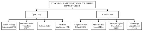
Figure 1.
Synchronization methods for three-phase systems.
In the development stage of a control strategy for power converters, the implementation of a synchronization method needs to be experimentally validated before it can be used in the electrical power system. In addition, the validation stage allows for the evaluation of the algorithm’s performance under different scenarios or grid voltage disturbances, such as (i) sag, (ii) swell, (iii) harmonics, (iv) frequency variations, and (iv) unbalance between phases.
Previous works have used different tools to validate the synchronization algorithms experimentally. These tools can be classified into (i) emulated digital processing systems (EDPSs) and (ii) acquisition from the electrical system (AES) (Figure 2). Works that use EDPSs can emulate electrical signals using computational simulations. In [22], the authors simulated the power grid voltages and implemented the synchronization algorithms using MATLAB/Simulink. Their work analyzed the synchronization capability of the algorithms in distributed generation systems during balanced and unbalanced conditions by comparing the overshoot (OS) of the frequency step changes. In [23], the synchronization algorithms were implemented externally using an electronic board to acquire the simulated signals and to execute the algorithms, a concept known as a processor in the loop (PIL). With the above, the authors evaluated the performance of a photovoltaic inverter connected to the grid where the electrical system and the photovoltaic inverter were simulated in MATLAB/Simulink, and the synchronization systems were implemented on the STM32F407-based board. In [24], several algorithms were evaluated by connecting two electronic devices based on micro-computerized systems: one for the emulation of the electrical grid and the second for the execution of the synchronization algorithms. The work compared the response time, the accuracy, and the computational efficiency in an ideal electrical system and a grid with harmonics distortion. The grid emulation and execution methods were implemented in digital systems with real-time simulation capability using a compact development environment based on a field-programmable gate array (FPGA) and/or digital signal processors. The platform also generated emulated signals for an external platform. In [25], an unbalanced electrical system with voltage harmonics was experimentally evaluated considering the OS and steady-state (ST) estimation of frequency ripple. Moreover, the work evaluated the algorithms using computational simulations, considering balanced and unbalanced grid and voltage variations such as sag, phase step change, and direct current (DC) offset. In [26], several algorithms used in distributed generation systems were evaluated for disturbances such as amplitude and frequency variations, unbalance, and harmonics. In [27], due to their hardware and software characteristics, these platforms were also used to evaluate distributed systems.
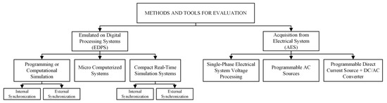
Figure 2.
Classification of evaluation tools.
The works that use AES require the equipment to acquire, process, and generate three-phase alternating current voltages. In [28], a converter connected to a single-phase electrical system was used. In [29], disturbances such as unbalance and harmonics, frequency and phase changes, and sag voltage were programmed in the output voltages of a three-phase inverter. The algorithms were implemented on the Infineon XMC 4500-based platform and were evaluated by analyzing the root-mean-square error (RMSE), mean error (ME), OS, settling time (ts), and process time. In [30], a programmable alternating current source was used. The paper evaluated the performance of synchronization algorithms when changing the phase in a grid with the presence of sag, frequency deviations, and DC offset. The work compared the frequency ripple, ts, and implementation complexity. Finally, Ref. [31] emulated the voltages with an inverter converter connected to a programmable DC source and used frequency estimation, phase estimation, and ts to compare the algorithms used.
The cost of implementing the different evaluation tools depends on the prices of the equipment or devices used (Table 1). In particular, the cost of the tools based on computational simulation is in the upper-low (from USD 100 to USD 1000) to medium (from USD 1000 to USD 10,000) price range, depending on the type of software license. The micro-computerized systems have a low price range of implementation (less than USD 100). The cost of implementation of the real-time simulation systems and the AES tools is in the range of medium to high (over USD 10,000).

Table 1.
Prices of the equipment used to validate synchronization methods.
The real-time simulation systems stand out from other methods without grid connection of their computational capacity. Examples of real-time simulation systems include PLECS RT Box, Typhon HIL404, RT-LAB, and Micro-LabBox. However, when considering accessibility, the methods based on computational simulation and micro-computerized systems stand out for their versatility and lower cost (see Table 1). This way, microcontroller-based systems allow for the implementation of an accessible experimental tool for evaluating and validating synchronization methods.
This work proposes a new evaluation tool for synchronization algorithms implemented in digital devices. The proposal is based on the emulation of the electrical grid using the Texas Instruments LAUNCHXL-F28379D development platform, and it describes the required peripherals and the methodology of its use for both validation and performance evaluation. The main objective is to provide a tool for engineers and researchers for the experimental validation and evaluation of digital synchronization algorithms before their implementation in grid-connected equipment.
The main contributions of this work are (i) to propose a low-cost and versatile digital platform for the experimental evaluation of synchronization techniques, (ii) to present a methodology of its use for the experimental evaluation of synchronization techniques, and (iii) to illustrate the uses and advantages of the proposal via the experimental validation of synchronization techniques based on PLL. All of these contributions focus on power converters based on RESs for electric power injection.
The remainder of this document is organized as follows: Section 2 presents the evaluation tool and methodology for the validation and evaluation of digital synchronization algorithms. Section 3 presents the main results when implementing the evaluation tool and evaluating two digital synchronization techniques based on PLL. Finally, Section 4 presents the main conclusions.
2. Evaluation Tool and Methodology of Use
The evaluation tool has three elements: (i) the emulator, (ii) a digital controller, and (iii) the methodology of use (Figure 3):
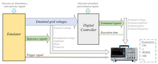
Figure 3.
Diagram of the proposed evaluation tool.
- The emulator is a low-cost digital platform where the voltages of a three-phase grid are emulated and where reference signals such as amplitude, phase, and frequency are generated to evaluate the synchronization algorithms. These signals must be visualized with an oscilloscope. The emulator can generate disturbances such as voltage harmonics and frequency variations and, also, generate unbalance between phases.
- The digital controller is a second digital platform that implements synchronization algorithms and, therefore, implements the controller for the power converter. The digital controller acquires the emulated grid voltages, processes them, and generates the estimated signals for the synchronization algorithms.
- The methodology of use is the action to be executed for the correct connection between the emulator and the digital controller; it includes actions to evaluate and compare the performance of the synchronization algorithms. Additionally, the methodology indicates the configuration of an oscilloscope for applying the methods.
The voltage grid generated by the emulator can be configured according to the test to be performed, allowing us to set the (i) amplitude, (ii) phase, (iii) frequency, and (iv) harmonic content of the grid. Different case studies can be predefined and selected through a simple interface built from switches.
The algorithm implemented in the digital controller will estimate the frequency, phase, and amplitude of the acquired grid voltages. The digital controller must generate the following analog signals using the estimated values computed by the synchronization algorithm: (i) synchronized grid voltages, (ii) amplitude, (iii) phase, and (iv) frequency. In the event that several methods or configurations need to be evaluated, external switches allow for the selection of these methods or configurations, allowing different estimated signals to be shown with the limited digital-to-analog converters (DACs) that are typically available.
The evaluation and validation of the synchronization algorithms are performed by comparing and analyzing the emulated grid voltages, the reference signals, and the signals estimated in the digital controller. A digital oscilloscope is required to display the signals and compute some numeric indicators. Moreover, the execution time (tex) of the algorithms is evaluated through a digital output on the digital controller. The emulator generates a synchronization signal to be used as a trigger for the correct visualization of the signals in the oscilloscope.
For the performance analysis of the algorithms, the reference and the estimated signals are compared using the (i) overshoot (OS), (ii) settling time (ts), (iii) root-mean-square error (RMSE), and (iv) mean error (ME). The performance evaluation also considers the (v) execution time of the algorithm in the digital controller.
The implementation requires that the digital platform must have at least three (DACs) or pulse-width modulated (PWM) outputs with low-pass, which will be used for the three-phase signals. Furthermore, the digital platform requires at least one DAC to generate the fundamental voltage, amplitude, phase, or frequency references, which will be displayed in the oscilloscope and used as references for the evaluation. Finally, the digital controller requires three analog-to-digital converters (ADCs) and at least one DAC to display the estimated signals. The emulator and the digital controller require each one to have at least one digital output and two digital inputs.
The following subsections present (i) the emulator’s implementation using the Texas Instruments digital development platform and (ii) the methodology of use. The methodology presents the stages to be executed, from the connection of the digital platforms up to the methods for evaluating the synchronization algorithms.
2.1. The Evaluation Tool
Figure 4 shows a schematic of the proposed evaluation tool using the Texas Instruments C2000-based board as the emulator. The cost of this board is close to USD 50, which is in the lower price range (Table 1). The board is a digital platform used in the field of motor control, power converters, and digital signal processing. The emulator generates the (i) emulated voltages of a three-phase system, ,
, and , (ii) the reference voltage , (iii) the synchronization signal and (iv) the analog output signals and .
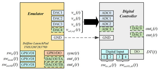
Figure 4.
Diagram of the proposed evaluation tool based on the LAUNCHXL-F28379D board.
The digital input signal allows for assigning to the outputs and the internal reference signals of (i) amplitude , (ii) phase , and (iii) frequency . Additionally, the digital input signals and allow us to modify the previously configured content and reference signals. Table 2 shows a summary of the signals in the emulator.
Table 2.
Description of the emulator signals.
The digital controller requires four ADCs, two DACs, and five digital inputs/outputs (DIOs). The digital controller specified in Figure 3 uses the input signal to select the estimated signals and generate them at the outputs and . The estimated signals correspond to the (i) grid voltage , (ii) amplitude , (iii) phase , and (iv) frequency . A second digital input signal allows the synchronization technique to be selected when evaluating multiple algorithms. On the other hand, the digital output enables the signal to be obtained for the calculation of the execution time. Table 3 shows a summary of the signals in the digital controller.
Table 3.
Selections of harmonic content, case studies, and DAC signals in the emulator.
2.2. The Methodology of Use
The procedure to implement the evaluation tool considers five stages, from the connection of the emulator and digital controller to the evaluation of the synchronization techniques (Figure 5).
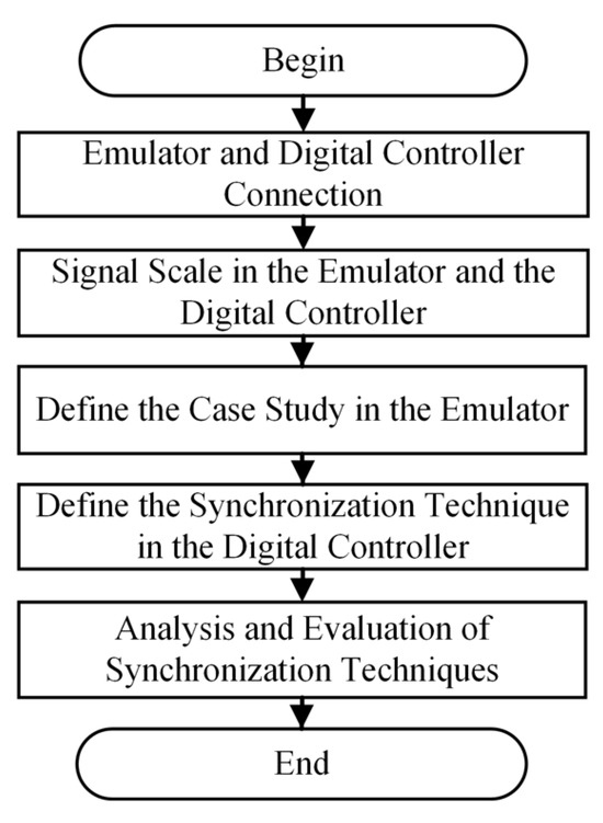
Figure 5.
Proposed methodology of use.
2.2.1. Connection of the Emulator to the Digital Controller
To avoid electrical damage to the board, the connection must consider the operating voltage ranges of the DACs in the emulator and the ADCs in the digital controller. The DACs and ADCs shown in Figure 4 operate in the [0, 3.3] V range, which enables the direct connection between the emulator and digital controller in the 3.3 V CMOS standard. In particular, the analog outputs of the emulator, identified as DACx, are obtained through PWM outputs with a low-pass filter and, also, operate in the range of [0, 3.3] V.
If the ADCs and DACs do not operate in the same range, it is possible (i) to program the internal signals of the emulator and digital controller to operate in an allowed voltage range or (ii) to use a conditioning circuit. An example of this type of circuit is shown in Figure 6 [32].
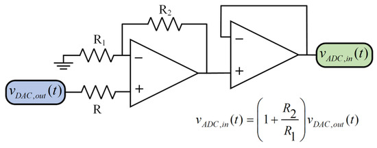
Figure 6.
Example of a conditioning circuit.
2.2.2. Signal Scale in the Emulator and the Digital Controller
The grid voltages generated on the emulator’s DACs are scaled from [0, 4095] counts to [0, 3.3] V when a 12-bit resolution is used (Figure 7), generating a voltage within [0.825, 2.475] V when the internal voltage of the emulator varies within [−1, 1] p.u. or within [1023, 3071] counts. The emulated voltages have a zero average value at 2047 counts or 1.65 V at the output of the DACs. The emulated voltages are acquired by the 12-bit ADCs of the digital controller and scaled in the same digital range. However, the 12-bit DACs of the digital controller consider a different conversion of the voltage signals, from [−1, 1] p.u. to [1, 2] V due to a smaller output voltage range. Table 4 proposes the conversions to be used in the DACs of the emulator and digital controller to evaluate the estimated and reference signals on an oscilloscope.
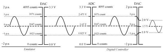
Figure 7.
Emulated voltage signals scaled.
Table 4.
Summary of the signals scaled in DACs.
2.2.3. Emulator: How to Define a Case Study
The grid voltage can be emulated mathematically by the emulator. The mathematical expression of these signals is shown in Equation (1) where the (i) amplitude, (ii) frequency, and (iii) phase can be modified to evaluate different variations in a balanced three-phase system. The emulator allows for setting the voltage ranges determined by electrical standards and regulations. In particular, the emulator considers two case studies: (i) response to amplitude changes and (ii) response to frequency changes. Both cases can be implemented in an emulated grid without harmonics and with a set of harmonics, including the 5th, 7th, and 11th components, each with 10% of the amplitude at the fundamental frequency. Table 5 shows the references of case study 1 for amplitude and phase, considering a null initial phase shift and a fixed frequency of 50 Hz. Table 6 shows the references for case study 2 with a fixed amplitude of 1 p.u. and a null initial phase shift. The reference signals for both cases are shown in Figure 8. To change the case study, such as the harmonic content, and to select the emulator reference signals (Figure 4), digital inputs can be used, as shown in Table 7.
Table 5.
Case study 1: amplitude changes.
Table 6.
Case study 2: frequency changes.
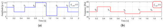
Figure 8.
Reference for the amplitude and frequency references: (a) case study 1; (b) case study 2.
Table 7.
Selection of harmonics, case study, and DAC output signals in the evaluation tool.
2.2.4. Digital Controller: Define Synchronization Technique
The synchronization techniques can be set by the digital signal when multiple methods are programmed in the digital controller. For example, Table 8 shows four combinations for PLL-based synchronization techniques.
Table 8.
Synchronization technique selection.
2.2.5. Methods and Evaluation of Synchronization Algorithms
The evaluation tool considers the evaluation of the synchronization algorithms using indicators such as the (i) mean error (ME) and (ii) root-mean-square error (RMSE) between the reference and estimated steady-state (SS) signals, as well as the (iii) settling time (), (iv) overshoot (OS) at step change, and (v) execution time ().
The evaluation process considers the following steps after connecting the digital controller to the emulator, selecting the algorithm and the case study to be implemented:
- 1.
- To evaluate the emulated and estimated signals from the three-phase grid:
- Display the next signals in the oscilloscope: , , and ;
- Obtain the instantaneous error between and , and compute the steady-state ME and RMSE; can be computed using the mathematical function of the scope (), while the ME and RMSE can be computed using the average value and the rms value of the channel of the mathematical function.
- 2.
- To evaluate the reference and estimated amplitude and frequency:
- Display the next signals in the oscilloscope: , , , and ;
- Compute and OS in a transient state (TS); it is possible to obtain the instantaneous error of the frequency and/or amplitude , and to calculate the steady-state EM; and can be computed using the mathematical function of the scope (, ), while the ME can be computed using the average value of the channel of the mathematical function.
- 3.
- To evaluate the reference and the estimated phase:
- Display the next signals in the oscilloscope: , ;
- Calculate the phase angle between signals; the signals and vary as a sawtooth signal within the range [0, 360] °; the phase angle can be computed using the phase measurement of the oscilloscope.
- 4.
- Evaluate the of the synchronization algorithms:
- Display the signal in the oscilloscope: ;
- Use the calculation method proposed in [33], which uses a digital output to determine , keeping the output in a high state during the algorithm execution; measures the time of the high state (); and subtracts the execution time from the previously determined high–low state change () (Equation (2) and Figure 9); can be computed using the positive pulse-width measurement of the oscilloscope.
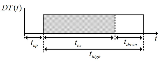 Figure 9. Execution time measurement method.
The oscilloscope must be configured considering the voltage range of the output signals, the methods of analysis selected, and the position of the emulated, reference, and estimated signals to be displayed. Table 9 proposes three configurations for a four-channel oscilloscope with digital inputs:
Table 9.
Proposed configurations for oscilloscope channels.
- Configuration I: Evaluation of the emulated and estimated signals of the three-phase grid, , , and ;
- Configuration II: Evaluation of the reference and estimated amplitude, phase, and frequency;
- Configuration III: Evaluation of the execution time of the synchronization algorithms.
3. Results
To demonstrate the feasibility of the proposal, the following stages are presented: (i) the experimental implementation of the evaluation tool and (ii) the evaluation of two synchronization methods considering the proposed case studies for ideal three-phase electric systems and electrical systems with harmonic content.
3.1. Experimental Implementation of the Evaluation Tool
The evaluation tool presented in Section 2.1 (Figure 4) is implemented using the steps of the proposed methodology (Figure 5). Figure 10 shows the connection between the emulator and the digital controller, while Figure 11 shows the experimental setup used.
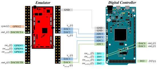
Figure 10.
Connection between LAUNCHXL-F28379D and Arduino Due digital platform.
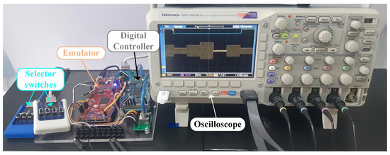
Figure 11.
Implementation of the proposed evaluation tool.
The digital controller is implemented on an Arduino Due board, which is an accessible platform and can be used as a digital control platform for three-phase power converters [32]. In particular, Figure 10 shows the emulated voltages , , and generated by the emulator, along with the output signals of the synchronization algorithms implemented in the digital controller.
In order to illustrate the performance of the proposal, Figure 12 and Figure 13 show the emulated grid signals and the reference signals generated by the emulator for different case studies. In particular, Figure 12a,b shows the emulated grid voltage and the fundamental reference voltage with amplitude 1 p.u. and a frequency of 50 Hz, without harmonic and with the presence of harmonics, respectively. Figure 12c,d shows the amplitude and frequency references for case studies 1 and 2, respectively. In case study 1, the references are programmed to change at in the falling edge of the signal and at in the rising edge. References from case study 2 are synchronized with the falling edge of at change . Figure 12e shows the variations in the emulated voltage and reference voltage of case study 1 generated by the emulator.
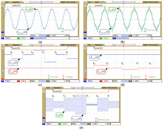
Figure 12.
Emulated and reference signals generated by the emulator: (a) and with amplitude 1 p.u., 50 Hz, and without harmonics; (b) and with amplitude 1 p.u., 50 Hz, and with harmonics 3, 5, and 11; (c) reference changes for case study 1; (d) reference changes for case study 2; (e) emulated voltage and fundamental reference for case study 1.
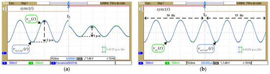
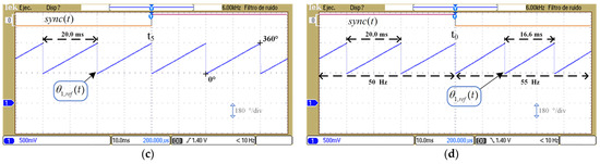
Figure 13.
Emulated and signals generated by the Emulator with reference changes: (a) and for change in case study 1; (b) and for change in case study 2; (c) for change in case study 1; (d) for change in case study 2.
Figure 13 shows the signals , , and generated in the emulator for the change in case study 1 and for the change in case study 2 (Table 5 and Table 6). The signals of case study 1 in Figure 13a show the voltage variation from a reference amplitude of 1 p.u. to 0.5 p.u. and a phase jump from 0° to 20°. On the other hand, the voltage signals in case study 2 vary in frequency from 50 Hz to 55 Hz, maintaining their amplitude at 1 p.u. and phase zero (Figure 13b).
The phase reference for case studies 1 and 2 is shown in Figure 13c,d, respectively. Phase varies as a sawtooth signal between 0° to 360°, considering frequency changes and not phase jump. The period of the signal varies with the change in the reference frequency from 50 Hz to 55 Hz at a time in case study 2.
3.2. Evaluation of Synchronization Algorithms
The results of evaluating two PLL-based synchronization techniques using the proposed evaluation tool and method are presented as examples of use. The synchronization algorithms were (a) SRF-PLL and (b) DSOGI-PLL with LPF. Figure 14 shows the operation diagrams of the synchronization algorithms implemented based on [18,21]. The algorithms were programmed using the Arduino Due board and configured according to [21]. The ADCs of the digital controller are 12-bit and work with 96 samples per cycle of the fundamental frequency. The parameters of the synchronization algorithms are , , , and a maximum grid amplitude of 1.5 p.u. Table A1 in Appendix A shows the parameters used in the digital controller.
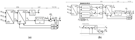
Figure 14.
Diagrams of the synchronization algorithms: (a) synchronous reference frame PLL (SRF-PLL); (b) dual second-order generalized integrator PLL (DSOGI-PLL) with a low-pass filter (LPF).
3.2.1. Case Study 1: Amplitude Changes
Figure 15 and Figure 16 show the results of implementing the SRF-PLL and DSOGI-PLL with LPF synchronization algorithms under a power grid with amplitude changes (Table 5). Figure 15 shows the performance of the algorithms in a grid without harmonic content, allowing us (i) to evaluate the dynamic response of the estimated amplitude and estimated frequency when the amplitude reference changes in step forms (Figure 15a), (ii) to observe the instantaneous error of the estimated voltage when the reference amplitude decreases from 1.0 p.u. to 0.5 p.u. with a phase jump of 20° a (Figure 15b), (iii) to compute the ME and RMSE between the reference voltage and estimated voltage at SS (Figure 15c), and (iv) to determine the OS and from the dynamic response of the amplitude to a step change (Figure 15d).

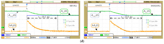
Figure 15.
The performance of the SRF-PLL (left column) and DSOGI-PLL with LPF (right column) algorithms with the proposed evaluation tool. Case study 1, amplitude change without harmonic content: (a) references and estimated signals in digital controller outputs; (b) reference, estimation, and error of voltage in change ; (c) reference, estimation, and error of voltage in a steady state of , measuring ME and RMSE of ; (d) amplitude signals in the transient state for change , measuring and OS in .
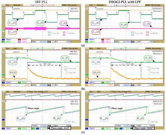
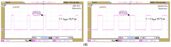
Figure 16.
The performance of the SRF-PLL (left column) and DSOGI-PLL with LPF (right column) algorithms with the proposed evaluation tool. Case study 1, amplitude change with harmonic content: (a) references and estimated signals in digital controller outputs; (b) reference, estimation, and error of voltage in change , measuring and OS in ; (c) Phase signals in a steady state of , measuring phase angle; (d) signal in a steady state after variation in for the calculation of the execution time.
Figure 16 shows the performance of the algorithms in a grid with harmonic content, allowing us (i) to observe the dynamics of the amplitude and frequency (Figure 16a). In particular, for the frequency variation at , Figure 16b shows the transient response of the frequency where the OS and are obtained, (ii) the estimated phase , and fundamental reference (Figure 16c), and (iii) the signal for calculating the execution time of the algorithms implemented in the digital controller. The execution time considers the time equal to 2.1 µs [34].
The implementation of the evaluation methods shown in Figure 15 and Figure 16 and Table 10 allows us (i) to verify the operation of the synchronization algorithms implemented in the digital controller and (ii) to know the response of the algorithms to variations in amplitude and harmonic content of 5th, 7th and 11th order. In particular, the results show (i) how the harmonic content affects the estimated frequency when using SRF-PLL (Figure 16a), (ii) a lower error of the estimated voltage in SS of time when using DSOGI-PLL with LPF (see the RMSE values in Table 10), and (iii) an of the DSOGI-PLL algorithm being 91% higher than that of the SRF-PLL algorithm. The results confirm the behavior of the SRF-PLL algorithm under distorted grid conditions reported in [8].
Table 10.
Summary of evaluation methods for case 1, change in .
3.2.2. Case Study 2: Frequency Changes
The dynamics of the estimated amplitude and frequency when varying the reference frequency are shown in Figure 17 and Figure 18. Figure 17 shows the results for a grid without harmonics, and Figure 18 shows the results for a grid with the harmonics content. In particular, for the variation in , the estimated frequency can be evaluated by obtaining the OS and from the dynamic response (Figure 17b and Figure 18b). Table 11 shows for DSOGI-PLL with LPF. The results confirm the behavior of the SRF-PLL algorithm under distorted grid conditions and the dynamics of the estimated frequency of the DSOGI-PLL algorithm reported in [8,29], respectively.
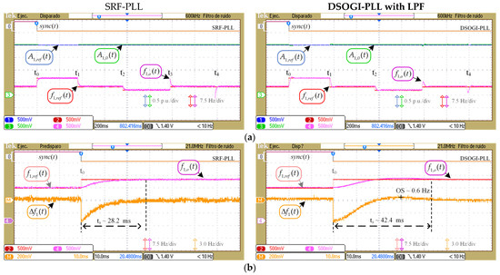
Figure 17.
The performance of the SRF-PLL (left column) and DSOGI-PLL with LPF (right column) algorithms with the proposed evaluation tool. Case study 2, frequency change without harmonic content: (a) references and estimated signals; (b) reference, estimation, and error of frequency in change , measuring and OS in with .
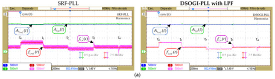
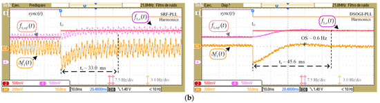
Figure 18.
The performance of the SRF-PLL (left column) and DSOGI-PLL with LPF (right column) algorithms with the proposed evaluation tool. Case study 2, frequency variation with the harmonic content: (a) references and estimated signals; (b) reference, estimation, and error of frequency in change , measuring and OS in with .
Table 11.
Evaluation methods in the transient state for case 2, change in .
4. Conclusions
This work presents a low-cost and versatile digital evaluation tool for the experimental evaluation of synchronization techniques. The evaluation tool emulates the voltage signals of an electric grid to be acquired and processed by any digital controller capable of implementing a synchronization algorithm. The emulator also generates reference signals to evaluate the synchronization algorithms implemented in a digital controller. The cost of the evaluation tool, considering the emulator platform, is in the low range compared to other tools (Table 1), at less than USD 100.
The methodology of use presented here allows for the correct tool to be implemented and the algorithms to be evaluated when digital platforms are used. The evaluation considers steady-state and transient analyses of the voltage, frequency, and amplitude estimated by the synchronization algorithms using the OS, , ME, and RMSE. The calculated execution time is another indicator considered in the evaluation of algorithms. The methodology is replicable on different digital platforms and allows different disturbance ranges to be set, including those defined by electrical standards and regulations.
The proposal was validated through an experimental implementation of the evaluation tool through the LAUNCHXL-F28379D platform. The emulator allows for the validation of digital synchronization algorithms such as SRF-PLL and DSOGI-PLL with LPF by implementing them in a digital controller (Arduino Due platform), varying the amplitude and the frequency and considering the harmonic content. The experimental results confirmed the performance of the algorithms reported in [8,29]. In particular, the high impact of harmonics on SRF-PLL (Figure 16a and Figure 18b) and the longer execution time of DSOGI-PPL (Table 10) were verified. The execution time of DSOGI with LPF was 91% longer than that of SRF-PLL (63.61 µs vs. 33.17 µs).
Author Contributions
Conceptualization, M.E.R., P.E.M. and E.E.; methodology, M.E.R., P.E.M., C.R.B. and C.P.; software, M.E.R. and P.E.M.; validation, M.E.R. and P.E.M.; formal analysis, M.E.R. and P.E.M.; resources, P.E.M.; writing—original draft preparation, M.E.R. and P.E.M.; writing—review and editing, M.E.R., P.E.M., E.E., C.R.B. and C.P.; visualization, M.E.R., P.E.M. and B.C.; supervision, P.E.M. All authors have read and agreed to the published version of the manuscript.
Funding
The Chilean Government funded this research through the ANID BECAS/DOCTORADO NACIONAL 21231463 scholarship, ANID/FONDEQUIP/EQM210178, and UBB INN I+D 23-54.
Institutional Review Board Statement
Not applicable.
Informed Consent Statement
Not applicable.
Data Availability Statement
The data presented in this study are available on request from the corresponding author due to privacy restrictions.
Acknowledgments
The authors would like to thank the Laboratorio de Acondicionamiento y Conversión de Energía (LACE) at the Universidad del Bío-Bío, Chile, and Thematic Network RIBIERSE-CYTED 723RT0150, for technical support.
Conflicts of Interest
The authors declare no conflicts of interest.
Abbreviations
The following abbreviations are used in this manuscript:
| RESs | renewable energy sources |
| DERs | distributed energy resources |
| ESSs | energy storage systems |
| PLL | phase-locked loop |
| SRF-PLL | synchronous reference frame PLL |
| MAF-PLL | moving average filter PLL |
| CDSC-PLL | adaptive cascaded delayed signal cancellation PLL |
| DSOGI-PLL | dual second-order generalized integrator PLL |
| LPF | low-pass filter |
| EDPS | emulated digital processing systems |
| AES | acquisition from the electrical system |
| OS | overshoot |
| PIL | processor in the loop |
| FPGA | field programmable gate array |
| DC | direct current |
| RMSE | root mean square error |
| ME | mean error |
| settling time | |
| DACs | digital-to-analog converters |
| PWM | pulse-width-modulated |
| ADCs | analog-to-digital converters |
| DIOs | digital inputs/outputs |
| execution time | |
| TS | transient state |
| SS | Steady state |
Appendix A
Table A1.
Parameters for the digital controller.
Table A1.
Parameters for the digital controller.
| Variable | Description | Value |
|---|---|---|
| n | Number of samples per fundamental cycle | 96 |
| Fundamental grid frequency | 50 Hz | |
| PLL | ||
| LPF constant | 222.1441 | |
| Integral constant | 13,337 | |
| Proportional constant | 133.3333 | |
| DSOGI-PLL with LPF | ||
| Constant | ||
| LPF constant | 157.0796 |
References
- Rafique, Z.; Khalid, H.M.; Muyeen, S.M. Communication Systems in Distributed Generation: A Bibliographical Review and Frameworks. IEEE Access 2020, 8, 207226–207239. [Google Scholar] [CrossRef]
- Shimomura, M.; Keeley, A.R.; Matsumoto, K.; Tanaka, K.; Managi, S. Beyond the merit order effect: Impact of the rapid expansion of renewable energy on electricity market price. Renew. Sustain. Energy Rev. 2024, 189, 114037. [Google Scholar] [CrossRef]
- Hassan, Q.; Algburi, S.; Sameen, A.Z.; Salman, H.M.; Jaszczur, M. A review of hybrid renewable energy systems: Solar and wind-powered solutions: Challenges, opportunities, and policy implications. Results Eng. 2023, 20, 101621. [Google Scholar] [CrossRef]
- Nsaif, Y.M.; Hossain Lipu, M.S.; Ayob, A.; Yusof, Y. Hussain, Fault Detection and Protection Schemes for Distributed Generation Integrated to Distribution Network: Challenges and Suggestions. IEEE Access 2021, 9, 142693–142717. [Google Scholar] [CrossRef]
- Saeed, M.H.; Fangzong, W.; Kalwar, B.A.; Iqbal, S. A Review on Microgrids’ Challenges Perspectives. IEEE Access 2021, 9, 166502–166517. [Google Scholar] [CrossRef]
- Zhang, D.; Chen, Y.; Wang, L.; Liu, J.; Yuan, R.; Wu, J.; Zhang, Y.; Li, M. Control strategy and optimal configuration of energy storage system for smoothing short-term fluctuation of PV power. Sustain. Energy Technol. Assess. 2021, 45, 101166. [Google Scholar] [CrossRef]
- Amin, M. Phase-Tracking Robust-Synchronization-Loop for Grid-Connected Converters. IEEE Trans. Power Deliv. 2022, 37, 2953–2965. [Google Scholar] [CrossRef]
- Ullah, I.; Ashraf, M.C. Comparison of synchronization techniques under distorted grid conditions. IEEE Access 2019, 7, 101345–101354. [Google Scholar] [CrossRef]
- Konara, K.; Kolhe, M.L.; Sankalpa, W. Grid synchronization of DC energy storage using Voltage Source Inverter with ZCD and PLL techniques. In Proceedings of the International Conference on Industrial and Information Systems, Peradeniya, Sri Lanka, 18–20 December 2015; pp. 458–462. [Google Scholar] [CrossRef]
- Ahmed, H.; Biricik, S.; Benbouzid, M. Linear Kalman Filter-Based Grid Synchronization Technique: An Alternative Implementation. IEEE Trans. Ind. Inform. 2021, 17, 3847–3856. [Google Scholar] [CrossRef]
- McGrath, B.P.; Holmes, D.G.; Galloway, J.J.H. Power converter line synchronization using a discrete Fourier transform (DFT) based on a variable sample rate. IEEE Trans. Power Electron. 2005, 20, 877–884. [Google Scholar] [CrossRef]
- Hoppensteadt, F.C.; Izhikevich, E.M. Pattern recognition via synchronization in phase-locked loop neural networks. IEEE Trans. Neural Netw. 2000, 11, 734–738. [Google Scholar] [CrossRef] [PubMed]
- Bhandare, R.; Vaidya, K.; Suraparaju, K.R. Grid Synchronization using Machine Learning. In Proceedings of the Mysore Sub Section International Conference, Mysuru, India, 16–17 October 2022; pp. 1–6. [Google Scholar] [CrossRef]
- Da Silva, M.J.; Ferreira, S.C.; Da Silva, J.P.; Dos Santos, M.G.; Paganotti, A.L.; Barbosa, L.M. Equivalency between Adaptive Notch Filter PLL and Inverse Park PLL by Modeling and Parameter Adjustment. IEEE Latin Am. Trans. 2020, 18, 2112–2121. [Google Scholar] [CrossRef]
- He, X.; Liu, M.; Li, Y.; Hong, F.; Yang, J.; Jiang, F. Synchronous Reference Frame Paralleled MAF/DSC-Based PLL. In Proceedings of the Asia Energy and Electrical Engineering Symposium, Chengdu, China, 21–29 May 2020; pp. 361–364. [Google Scholar] [CrossRef]
- Golestan, S.; Guerrero, J.M.; Musavi, F.; Vasquez, J.C. Single-phase frequency-locked loops: A comprehensive review. IEEE Trans. Power Electron. 2019, 34, 11791–11812. [Google Scholar] [CrossRef]
- Golestan, S.; Guerrero, J.M.; Vasquez, J.C.; Abusorrah, A.M.; Al-Turki, Y. A Study on Three-Phase FLLs. IEEE Trans. Power Electron. 2019, 34, 213–224. [Google Scholar] [CrossRef]
- Golestan, S.; Guerrero, J.M.; Vasquez, J.C. Three-Phase PLLs: A Review of Recent Advances. IEEE Trans. Power Electron. 2017, 32, 1894–1907. [Google Scholar] [CrossRef]
- Taheri, P.; Amini, J.; Moallem, M. Improving Performance of Three-Phase MAF-PLL Under Asymmetrical DC-Offset Condition. IEEE Access 2023, 11, 111200–111211. [Google Scholar] [CrossRef]
- Safa, A.; Gouichiche, A.; Verma, A.K.; Su, C.-L.; Chedjara, Z.; Messlem, Y.; Berkouk, E.M. Open Loop Synchronization Techniques Benchmarking for Distributed Energy Sources Connection. IEEE Access 2022, 10, 63554–63566. [Google Scholar] [CrossRef]
- Peng, L.; Fu, Z.; Xiao, T.; Qian, Y.; Zhao, W.; Zhang, C. An Improved Dual Second-Order Generalized Integrator Phased-Locked Loop Strategy for an Inverter of Flexible High-Voltage Direct Current Transmission Systems under Nonideal Grid Conditions. Processes 2023, 11, 2634. [Google Scholar] [CrossRef]
- Mennai, N.; Soufi, Y.; Medoued, A.; Faleh, A. Grid Synchronization Techniques Analysis of DG Systems Under Grid Fault Conditions. In Proceedings of the International Multi-Conference on Systems, Signals & Devices, Sétif, Algeria, 6–10 May 2022; pp. 917–922. [Google Scholar] [CrossRef]
- Bouazza, F.; Mohamed, M.; Bouziane, B.; Abdelhamid, L. PIL Test for Voltage Source Inverter control used in Off-grid PV system. In Proceedings of the International Conference on Electrical Sciences and Technologies in Maghreb, Algiers, Algeria, 28–31 October 2018; pp. 917–922. [Google Scholar] [CrossRef]
- Nwobu, C.J.; Nakiganda, A.M.; Zhang, L. Grid Voltage Synchronization for Unbalanced Voltages Using the Energy Operator. IEEE J. Emerg. Sel. Top. Power Electron. 2017, 5, 1415–1424. [Google Scholar] [CrossRef]
- Ahmed, H.; Benbouzid, M. Adaptive Observer-Based Grid-Synchronization and Sequence Extraction Techniques for Renewable Energy Systems: A Comparative Analysis. Appl. Sci. 2021, 11, 653. [Google Scholar] [CrossRef]
- Kulkarni, S.V.; Gaonkar, D.N. An investigation of PLL synchronization techniques for distributed generation sources in the grid-connected mode of operation. Appl. Energy 2021, 290, 116755. [Google Scholar] [CrossRef]
- Wang, J.; Pratt, A.; Prabakar, K.; Miller, B.; Symko-Davies, M. Development of an integrated platform for hardware-in-the-loop evaluation of microgrids prior to site commissioning. Electr. Power Syst. Res. 2023, 223, 109535. [Google Scholar] [CrossRef]
- Chowdhury, M.R.; Galib, A.R.; Jobayer, A.M.; Hossain, S.; Isalm, M.N.; Islam, M.S. Impact of PLL Dynamics on Frequency Stability in Low Inertia Trending Power Systems. In Proceedings of the International Conference on Power, Control & Embedded Systems, Allahabad, India, 6–8 January 2023; pp. 1–6. [Google Scholar] [CrossRef]
- Pinto, J.; Carvalho, A.; Rocha, A.; Araújo, A. Comparison of DSOGI-Based PLL for Phase Estimation in Three-Phase Weak Grids. Electricity 2021, 2, 244–270. [Google Scholar] [CrossRef]
- Saxena, H.; Singh, A.; Chittora, P. Modified LMS synchronization technique for distributed energy resources with DC-offset and harmonic elimination capabilities. ISA Trans. 2023, 135, 567–574. [Google Scholar] [CrossRef] [PubMed]
- Ardalan, P.; Rasekh, N.; Khaneghah, M.Z.; Abrishamifar, A.; Saeidi, M. A modified SOGI-FLL algorithm with DC-offset rejection improvement for single-phase inverter applications. Int. J. Dyn. Control 2022, 10, 2020–2033. [Google Scholar] [CrossRef]
- Melin, P.; Baier, C.; Espinosa, E.; Riedemann, J.; Espinoza, J.; Pena, R. Study of the Open-Source Arduino DUE Board as Digital Control Platform for Three-Phase Power Converters. IEEE Access 2022, 10, 7574–7587. [Google Scholar] [CrossRef]
- Amestica, O.E.; Melin, P.E.; Duran-Faundez, C.R.; Lagos, G.R. An Experimental Comparison of Arduino IDE Compatible Platforms for Digital Control and Data Acquisition Applications. In Proceedings of the IEEE CHILEAN Conference on Electrical, Electronics Engineering, Information and Communication Technologies, Valparaiso, Chile, 13–27 November 2019; pp. 1–6. [Google Scholar] [CrossRef]
- Reyes, M.; Melín, P.; Espinosa, E.; Rivera, M.; Suárez, J. An Experimental Comparison between an Arduino Due and a DSP-based Delfino LaunchPad board. In Proceedings of the International Conference of the Chilean Computer Science Society, Santiago, Chile, 21–25 November 2022; pp. 1–8. [Google Scholar] [CrossRef]
Disclaimer/Publisher’s Note: The statements, opinions and data contained in all publications are solely those of the individual author(s) and contributor(s) and not of MDPI and/or the editor(s). MDPI and/or the editor(s) disclaim responsibility for any injury to people or property resulting from any ideas, methods, instructions or products referred to in the content. |
© 2025 by the authors. Licensee MDPI, Basel, Switzerland. This article is an open access article distributed under the terms and conditions of the Creative Commons Attribution (CC BY) license (https://creativecommons.org/licenses/by/4.0/).