Abstract
In this study, the design and optimization of some parameters thought to be effective in the convective heat transfer caused by an air jet impinging on a rotating heated cylindrical surface are investigated by using the Taguchi optimization method. The temperature distribution on the rotating cylindrical surface resulting from air jet impingement is measured with an infrared thermal camera, and the heat transfer due to the difference between the air jet temperature and the surface temperature is shown by Nusselt number. The effects of some major parameters such as the Reynolds number of the air jet, jet-to-surface distance, speed of the rotating cylinder, geometry of the nozzle, and constant surface temperature on Nusselt number are evaluated by means of Analysis of Variance (ANOVA). As a result, the Reynolds number, surface temperature, and rotational speed are found to play key roles in enhancing heat transfer under the tested conditions. The results provide valuable insight for thermal management applications such as gas turbines, brake disks, and electronic cooling, and the adopted Taguchi-based approach may serve as a systematic framework for future studies involving nanofluids and multi-jet systems.
1. Introduction
Jet impingement cooling has been regarded as one of the most effective strategies for enhancing convective heat transfer in engineering systems, primarily due to its ability to induce high local heat transfer coefficients by disrupting thermal boundary layers [1]. This makes jet impingement cooling highly effective for applications involving high thermal loads, including braking systems, rotating drums, gas turbine components, and electronic modules, as well as in cylindrical machinery where efficient thermal regulation is important for performance and longevity [2].
Although the fundamental physics of impinging jets on stationary flat plates have been extensively studied, extending the configuration to rotating cylindrical geometries introduces significant complexities. The superposition of tangential (rotation-induced) and axial (jet-induced) velocity components alters canonical stagnation behavior, leading to displaced stagnation zones, asymmetric wall jets, vortex interactions, and three-dimensional instabilities [3,4]. These phenomena can also be influenced by the effects of centrifugal and Coriolis forces, which modify the wall jet trajectory, promote secondary vortex formation, and redistribute local heat transfer patterns [5,6].
The directionality between jet flow and surface rotation is another pivotal factor. In counter-rotating systems, enhanced turbulence intensity and stagnation pressure typically increase local and average Nusselt numbers, while in co-rotating conditions, the impingement core weakens, thereby diminishing overall cooling performance [7]. Such flow asymmetry has been repeatedly observed in both experimental and numerical studies, underscoring the nonlinear character of jet–rotation interactions [8,9]. Within this framework, Reynolds number (Re), rotational speed (Ucr), jet-to-surface spacing (H/Dh), and nozzle geometry have emerged as the principal governing parameters influencing cooling performance. Increasing Reynolds number intensifies turbulence and elevates both local and spatially averaged Nusselt numbers, though excessively high values may trigger flow instabilities [10]. Conversely, higher Ucr values can enhance turbulence in the stagnation region at moderate levels, but beyond critical thresholds they tend to deflect jet momentum and induce non-uniform heat transfer [11].
The jet-to-surface distance (H/Dh) further dictates the relationship between stagnation heat transfer and flow entrainment. Smaller distances yield strong stagnation cooling due to concentrated jet momentum, yet restrict entrainment and secondary mixing. Larger distances enhance flow mixing and improve radial uniformity of heat transfer, but reduce peak stagnation values [12]. For rotating disks, such trade-offs manifest as increased circumferential uniformity at the expense of maximum heat flux [13].
Nozzle geometry represents another dimension of complexity. Circular nozzles typically generate highly localized cooling peaks, while non-circular geometries—such as elliptical and slot nozzles—distribute the thermal footprint more uniformly, particularly under rotational conditions [14,15]. Complementary studies reveal that geometric modifications can significantly alter jet behavior and improve heat transfer [16]. Moreover, swirling jets have been shown to expand stagnation footprints and enhance flow mixing [17], while confinement effects alter boundary layer dynamics, further redistributing thermal loads in rotating systems [18].
İnvestigations of multi-jet impingement arrays have also highlighted the potential for cross-flow interactions to improve average cooling performance, particularly in rotating environments. It was demonstrated that multi-jet impingement on rotating disks significantly increases average Nusselt numbers by fostering enhanced flow mixing and broader impingement footprints [19,20]. Numerical analysis has demonstrated improved predictive capability in capturing transient vortex shedding and secondary flow interactions, albeit at substantially higher computational cost [9,11]. Building on these developments, data-driven methods are emerging as powerful predictive tools [20].
Despite these advancements, critical research gaps remain. Systematic experimental studies simultaneously exploring the coupled effects of Reynolds number, rotational speed, jet-to-surface distance, nozzle geometry, and surface temperature are scarce. Moreover, while computational and artificial learning models are advancing rapidly, they often lack sufficient experimental validation under rotating cylindrical conditions. The present study addresses these gaps by undertaking a comprehensive experimental investigation of jet impingement cooling on a rotating cylindrical surface, systematically varying nozzle geometry (circular, square and triangular), jet-to-surface distance to hydraulic diameter ratio (H/Dh = 3, 6, and 9), Reynolds number (Re = 2000–7000), rotational speed of cylinder (Ucr = 20, 40, 60 rpm), and constant surface temperatures (Ts = 45 °C, 60 °C, and 75 °C) of the rotating cylinder. The parameter combinations were designed by using a Taguchi L18 (61 × 34) orthogonal array, enabling efficient experimentation with statistically meaningful results.
2. Materials and Methods
This section outlines the experimental procedure, instrumentation, data reduction, and information about the applied optimization techniques.
2.1. Experimental Setup
The schematic representation and physical layout of the experimental system are illustrated in Figure 1a,b. The experimental setup consists of a controlled air delivery system and a thermally regulated rotating cylinder designed to simulate jet impingement scenarios under laboratory conditions. A centrifugal blower supplies airflow through a PVC pipeline system, directing it toward interchangeable nozzles mounted at a fixed height from the cylinder surface. The airflow path is designed with a length of 50 hydraulic diameters (Lh = 400 mm) between the blower and nozzle inlet to ensure fully developed flow conditions. Lightweight plastic piping is selected to minimize frictional loss and mechanical load.
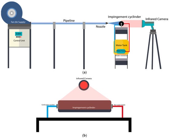
Figure 1.
Schematic views of the experimental setup: (a) front view, (b) side view.
The blower operates at a nominal speed of 2850 rpm and is connected to a variable frequency drive (VFD) for fine-tuned control of flow rate. The Reynolds number of the jet flow varies between 2000 and 7000 to simulate both laminar and turbulent regimes. The mass flow rate of air () are measured as 0.232 g/s, 0.349 g/s, 0.465 g/s, 0.581 g/s, 0.697 g/s, and 0.813 g/s, respectively, for 2000, 3000, 4000, 5000, 6000, and 7000 Reynolds number values. A height-adjustable platform is employed to set and maintain a consistent nozzle-to-surface distance across all test cases.
Jet velocity is quantified using a hot-wire anemometer (CEM DT-8880, Cem instruments, Shenzhen, China), which operates on thermal conductivity principles. This device offers a measurement range of 0.1–25 m/s with a resolution of 0.1 m/s and a velocity uncertainty of ±2.5%, as specified by the manufacturer. In addition to velocity, the anemometer also captures the jet temperature within the range of 0–50 °C, with an accuracy of ±1.5%. These dual measurements are critical for characterizing the flow field and determining the appropriate Reynolds number for each test.
Three nozzle types—circular, square, and triangular—are designed to have identical hydraulic diameters (Dh = 0.008 m) to ensure comparable flow conditions at the exit plane. The nozzles are fabricated using Fused Deposition Modeling 3D printing technology, employing polylactic acid filament due to its ease of processing and structural rigidity. Wall thicknesses are minimized to reduce aerodynamic resistance and preserve flow symmetry. Front and top views of the fabricated nozzles are depicted in Figure 2a. As an example, the outer and inner diameters and the contraction length of the circular nozzle are given in Figure 2b. The position of the hot-wire anemometer and nozzle is given in Figure 2c.
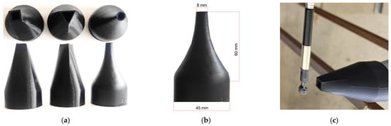
Figure 2.
Fabricated nozzles: (a) front and top views of all tested nozzles, (b) dimensions of the circular nozzle, and (c) positioning of square nozzle.
The rotating cylinder is an aluminum cylinder with 48 mm inner diameter, 50 mm outer diameter, and 250 mm length. Three values of constant surface temperatures are studied in this article (Ts = 45 °C, 60 °C, and 75 °C). The temperature difference between the inlet and the outlet of the cylinder is very low, which causes a constant temperature.
To enhance emissivity and minimize reflective errors, the cylinder surface is coated with a specialized matte black paint suitable for IR measurements. It is known that emissivity is a material’s ability to emit infrared radiation. Although black surfaces have high emissivity (bare aluminum emissivity is ε~0.05, black matte paint emissivity is ε~0.95), the surface is painted black to reduce the reflections because most real-world materials have lower emissivity and can reflect infrared radiation from their surroundings, leading to misleading temperature readings. Otherwise, the aluminum’s surface cannot show its true temperature—instead, it reflects heat from other nearby objects (like people, objects or lights), confusing the camera.
The rotating cylinder is actuated by a step motor with integrated encoder feedback, connected to the cylinder through a belt–pulley system to ensure smooth and vibration-free operation. Figure 3 shows the motion control system and cylinder. The rotational speed is adjustable between 0 and 100 RPM through a digital interface, allowing for systematic investigation of rotational effects on impingement heat transfer. Limit switches are installed along the x-axis to restrict motion range and ensure safe mechanical operation. The motor is programmed using pre-calibrated step counts to maintain rotational accuracy.
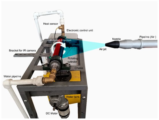
Figure 3.
Photo of the rotating cylinder system.
A high-resolution infrared thermal camera (Optris Xi 400, Optris, Portsmouth, NH, USA) is employed to capture the temperature distribution across the cylinder surface. The thermal camera specifications include a measurement range of 20–1500 °C, optical resolution of 390:1, and temperature accuracy of ±1.5%. All thermal data were recorded using Optris Pix Connect 3.23.3122.0 Full-frame thermal videos are saved in .ravi format, and pixel-level temperature data can be exported in .csv or .dat formats for further post-processing. The temporal evolution of temperature at specific surface points or regions is tracked throughout the experimental runs. In addition, environmental and flow parameters—including ambient temperature (T∞), jet velocity (Uj), jet temperature (Tj), and cylinder rotational speed (Ucr)—are logged before each test to ensure systematic data organization and repeatability operating conditions.
2.2. Measurement Procedure
We followed the measurement instructions as follows:
- o
- Start to rotate the cylinder at the desired speed (Ucr = 20, 40, and 60 rpm).
- o
- Run the resistors and heat the water in the tank that is maintained at room temperature (Tin,water).
- o
- Control the temperature with a thermostat during heating.
- o
- When the water temperature reaches an approximate value of the desired constant surface temperature (Ts = 45 °C, 60 °C, 75 °C) and steady-state conditions, pump it through the pipes and rotating cylinder.
- o
- When the temperature of the water at the outlet of the cylinder (Tout,water) is around the desired constant surface temperature, measure the outer surface temperature with an infrared camera.
- o
- If the temperature distribution confirms that the constant surface temperature is obtained (Ts = 45 °C, 60 °C, 75 °C), prepare the jet flow impingement procedure.
- o
- Send the airflow from the selected nozzle (circular, square, triangular) by running the fan at the desired mass flow rate of air ( = 0.232 g/s, 0.349 g/s, 0.465 g/s, 0.581 g/s, 0.697 g/s, and 0.813 g/s, respectively, for Re = 2000, 3000, 4000, 5000, 6000, and 7000) and jet-to-surface distance (H/Dh = 3, 6, and 9).
- o
- Monitor the temperature distribution with the camera. Record the transient and steady-state temperatures.
Figure 4 presents an image in which the outer surface of the cylinder has a constant temperature. As can be seen, the color is the same across the entire surface, and the temperature is approximately constant.
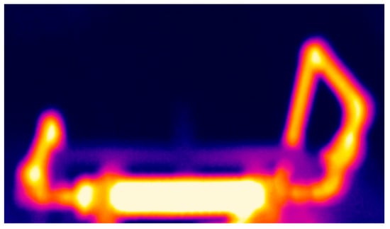
Figure 4.
Surface temperature of the cylinder just before impingement.
2.3. Data Reduction
The heat rate generated by heating water from room temperature to the desired temperature is calculated with the following equation:
where Qw is the total input heat of the water sent to the cylinder. The flow rate of the water is . Cp is the specific heat capacity of water (4180 J/kgK). T1 and T2 represent the temperature of water sent to the tank (at about room temperature) and the temperature of the water that reaches the cylinder (at about constant surface temperature), respectively.
Heat loss from the inner diameter to the outer diameter of the aluminum cylinder, namely heat conduction, is calculated as:
where kAl is the thermal conductivity of aluminum (237 W/m2K), Arc is the surface area (0.039 m2) of the rotating cylinder, Δx is the thickness of the cylinder (2 mm), and ΔTrc is the temperature difference between the outer and inner surfaces of the aluminum cylinder (ΔTrc = T2 − Ts). It should be noticed that the inner surface temperature is equal to the final water temperature in the cylinder.
The radiative heat transfer is calculated by the well-known formula:
where σ is the Stefan–Boltzmann constant (5.67 × 10⁻⁸ W/m2K4), ε is the emissivity of painted aluminum cylinder (0.95), Ts is the constant surface temperature of the cylinder, and T∞ is the ambient temperature of the room.
The net heat is then obtained by subtracting the loss heat from the total heat. The heat flux is then obtained by dividing by the heat transfer surface area of the rotating cylinder:
When the air issuing from the jet impinges to the surface of the cylinder and initiates a process of forced convection, leading to a reduction in the cylinder’s surface temperature, it can be reasonably inferred that the total heat supplied to the cylinder is dissipated primarily through forced convection, particularly due to the impingement of the jet. Therefore, it can be concluded that
The order of cooling is directly affected by the difference between the local surface temperatures (Tw,x) and the temperature of the jet flow (Tj). The heat transfer coefficient yields the Nusselt number (Nu):
where kair is the thermal conductivity of air (0.02623 W/mK), and Dh is the hydraulic diameter of the nozzle (0.008 m). To calculate the average Nusselt number (Nuavg), the arithmetic mean of all local Nusselt numbers (Nux) measured along the circumference distance x on the cylinder must be determined.
Reynolds number (Re) is calculated based on the mass flow rate of air and the hydraulic diameter of the nozzles:
Table 1 is prepared for a better understanding of the calculation method. The table shows the calculation of the Nusselt numbers for all 18 experiments, at only the stagnation point (Nust), which is the first point of impingement over the cylinder.

Table 1.
Measured and calculated values used to obtain Nusselt number at stagnation point.
2.4. Uncertainty Analysis
Uncertainty analysis is conducted by the method proposed by Kline and McClintock [21], which is one of the most widely adopted and rigorously validated approaches for assessing uncertainties in experimental measurements. The individual uncertainty values assigned to each of these variables are summarized in Table 2.
Table 2.
Uncertainties of independent and dependent values.
Average uncertainty values for the Nu number and Re number are found to be ±3.33% and ±2.63%, respectively. The primary source of uncertainty for the Nu number is the surface temperature. For the Re number, the principal source of uncertainty is the jet velocity.
2.5. Design of Experiments
The Taguchi method is a highly effective statistical approach for developing new processes or optimizing existing ones to enhance system performance and reliability. This technique employs a structured experimental design based on orthogonal arrays, which allows the comprehensive exploration of the parameter space with a minimal number of experimental runs. In this study, the experimental plan is constructed using an orthogonal array of the form L18(61 × 34), indicating that a total of 18 experiments are conducted. In this configuration, 1 parameter varies at 6 levels, while each of the remaining 4 parameters vary at 3 levels, as summarized in Table 3.
Table 3.
Orthogonal array.
The Taguchi method [23,24] is employed to optimize the experimental parameters using a statistical framework based on a loss function, which quantifies the deviation of experimental results from the desired performance. This loss function is subsequently transformed into a signal-to-noise (S/N) ratio, enabling the evaluation of the robustness and quality of the system’s response under varying experimental conditions. In the present study, the ‘higher-is-better (HB)’ criterion for the S/N ratio is selected, as the target is to maximize the performance characteristic. The performance measurement, denoted as ηij, corresponding to the jth experimental trial, is expressed as the logarithmic value of the S/N ratio for the HB case, as follows:
where Y represents the observed response value and n denotes the number of repeated measurements under same conditions.
In the investigation, 6 key parameters influencing heat transfer are identified and designated by the letters A–E. These letters correspond to the following design parameters: A—Reynolds number, B—jet-to-surface distance, C—rotational speed, D—nozzle geometry, and E—surface temperature. The corresponding quantitative levels of these factors are detailed in Table 4.
Table 4.
Design parameters.
3. Results
This section presents and discusses the results obtained from the experimental investigation in detail. All experiments are performed according to the orthogonal array design defined in Table 3, ensuring a systematic and statistically balanced assessment of the influencing parameters. To maintain clarity and uniformity throughout the study, each experimental run is designated as Case 1, Case 2, …, Case 18, corresponding precisely to the operating conditions listed in Table 2.
These case identifiers are consistently used in the subsequent analysis and discussion to refer to specific combinations of design parameters. This approach facilitates a clear comparison between different cases and allows for the systematic evaluation of how variations in these parameters influence the overall heat transfer performance.
3.1. Transient Temperature Distribution
In this section, the transient temperature contours are presented and discussed in detail. Specifically, Case 1 and Case 16 are selected for comprehensive analysis, as they represent the two extreme operating conditions within the experimental matrix. Case 1 corresponds to the scenario yielding the minimum heat transfer performance, while Case 16 exhibits the maximum results. By examining these two contrasting cases, the temporal evolution of the temperature distribution and the influence of operating parameters on the heat transfer behavior can be more clearly demonstrated.
Case 1 represents the configuration in which all parameters take their lowest levels (A = 1, B = 1, C = 1, D = 1, E = 1,). In this case, the Reynolds number is Re = 2000, corresponding to a laminar flow regime. The speed of the rotating cylinder Urc is 20 rpm. The dimensionless nozzle-to-cylinder distance is H/Dh = 3. A circular nozzle geometry with constant temperature Ts = 45 °C is employed in this setup. The thermal camera images obtained under these conditions are presented in Figure 5. Case 16 is shown in Figure 6 where the Re number is 7000, H/Dh is 3, Urc is 60 rpm, a square nozzle is used, and Ts is 70 °C.
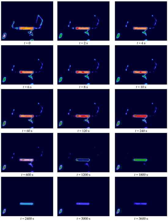
Figure 5.
Thermal camera images of Case 1 (The color bar indicates the temperature, ranging from cold (blue) to hot (red).
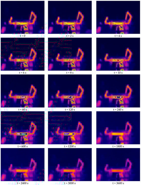
Figure 6.
Thermal camera images of Case 16 (The color bar indicates the temperature, ranging from cold (blue) to hot (red).
At t = 0 s, the jet begins to impinge on the heated surface, initiating the cooling process. The temperature gradually stabilizes, and by t = 3600 s, the system reaches steady-state conditions, where temperature variations become negligible. To verify this, the experiments were continued with additional temperature measurements taken at t = 4000 s and t = 4800 s. These readings showed deviations of only 0.5–1% from those at t = 3600 s, confirming that the system had achieved thermal equilibrium. As seen in the contours, the cooling effect increases radially from the stagnation point toward the edges. Over time, this pattern intensifies until a steady regime is reached, at which point the temperature at the stagnation region decreases, indicating the full establishment of the jet’s cooling influence.
In contrast, Case 16 corresponds to the configuration with the highest levels of all parameters, characterized by a Re number of 7000 and a square jet geometry. Thermal camera observations reveal that the impingement zone—the area affected by the jet—is significantly larger compared to Case 1. The cold regions expand distinctly, being approximately twice as wide, particularly at t = 3600 s, when steady-state conditions are established. This broader and more uniform cooling distribution is primarily attributed to the combined effects of higher jet momentum, increased surface temperature, and the square nozzle geometry, all of which enhance turbulent mixing and heat dissipation efficiency across the impinged surface.
3.2. Average (Nuavg) and Stagnation (Nust) Nusselt Numbers Under Steady State Conditions
The stagnation-point Nusselt number (Nust) and the average Nusselt number obtained over the cylinder surface are presented in Figure 7. According to knowledge in the literature, the cylinder rotation changes the stagnation Nusselt number mainly by (i) changing the relative tangential velocity at the wall (which alters shear and boundary-layer thickness) and (ii) shifting the stagnation location around the cylinder. If the surface rotates with the incoming jet flow (co-rotation, i.e., surface tangential speed in the same sense as a jet swirl), the local relative velocity at the stagnation region is reduced and then Nu decreases. If the surface rotates against the incoming jet (counter-rotation), the relative velocity at the wall increases then Nu increases. The rotation effect is small when the surface tangential speed is much less than the jet centerline velocity [12,14].
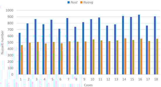
Figure 7.
Average and stagnation-point Nusselt numbers under steady-state regime.
The average Nusselt number (Nuavg) under steady-state conditions was obtained by averaging the local Nu values across the impinged surface after the system had reached thermal equilibrium. The analysis revealed that the lowest stagnation and Nusselt numbers are obtained in Cases 1, 2, and 3, whereas the highest values are recorded in Cases 16, 17, and 18. This pronounced variation can be primarily attributed to the influence of the Re, which directly governs the flow regime and convective heat transfer intensity. For the jets, the stagnation scaling is typically Nust ∝ Rem between about 0.5 and 0.8 (exact exponent depends on nozzle-to-surface distance, jet turbulence, confinement, etc. [14]). Specifically, the Re number was 2000 in the lowest-performing cases and 7000 in the highest, demonstrating a strong positive correlation between flow turbulence and heat transfer enhancement.
Figure 7 clearly emphasizes the dominant role of the Reynolds number, while also reflecting the secondary contributions of other factors such as nozzle geometry, surface temperature, and jet-to-surface distance. Together, these results highlight the sensitivity of the heat transfer process to both hydrodynamic and geometric parameters, underlining the critical importance of optimizing flow conditions to maximize cooling efficiency in jet impingement systems.
3.3. Results of Taguchi Optimization
The signal-to-noise (S/N) ratios presented in Table 5 demonstrate that the experimental design and results are reliable and consistent with the ‘higher is better’ criterion. Figure 8 illustrates the graphical representation of these S/N values, showing that the variations among the parameter levels remained within acceptable limits. The optimal levels are those corresponding to the highest S/N ratios and closest alignment with the mean reference line, which represents the overall performance stability. Table 6 and Table 7 show the results of ANOVA and optimum parameters.
Table 5.
Average S/N values for Nu number.
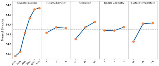
Figure 8.
S/N values.
Table 6.
ANOVA test results.
Table 7.
Optimum parameters.
According to the Taguchi analysis, the Re number emerged as the most significant factor influencing the heat transfer performance, contributing 73.52% to the total variation. This dominant contribution highlights the strong dependence of the average Nu number on flow dynamics and turbulence intensity. As Re increases, enhanced momentum exchange and thermal boundary layer thinning lead to a substantial improvement in heat transfer. This finding is fundamentally consistent with the established literature. The dominant role of Re as the primary driver of convective heat transfer is well-documented, as highlighted in the comprehensive review on moving surfaces by Habib and Al-Garni [1]. Our quantitative result (73.52% contribution) empirically confirms for this specific geometry that hydrodynamic forces (i.e., flow momentum and turbulence) are the principal mechanisms for boundary layer disruption, a finding that aligns with recent experimental work on rotating systems by Gulati et al. [16].
The surface temperature is the second most influential parameter, with a contribution of 14.74%, followed by rotational speed, which accounts for 10.19%. Both parameters are crucial in controlling the convective heat transfer coefficient. Higher surface temperatures enhance thermal gradients, while increased cylinder motion improves jet impingement uniformity and energy dissipation. While the strong contribution of surface temperature (14.74%) confirms the fundamental role of the thermal driving potential (i.e., Newton’s Law of Cooling), the significant contribution of rotational speed (10.19%) is a key finding specific to this study’s configuration. This result suggests a complex interaction: on one hand, rotation can introduce a ‘sweeping’ effect that removes the thermally saturated boundary layer, as noted by Karabay and Yilmaz [5] on rotating disks. On the other hand, excessive rotation can ‘deflect’ the jet, weakening its impact, as shown by Mohan et al. [9]. Our finding of a 10.19% positive contribution suggests that, within the tested 20–60 rpm range, the constructive ‘sweeping’ and mixing effects are more dominant than any detrimental deflection.
On the other hand, H/Dh and nozzle geometry shows relatively minor effects, contributing 0.91% and 0.36%, respectively. These parameters have limited impact under the current operating range, suggesting that their influence becomes more pronounced under higher Reynolds numbers.
The ANOVA results further confirm the significance of these findings, where Re number (p = 0.0001) and surface temperature (p = 0.0004) are statistically highly significant (p < 0.01), while rotational speed (p = 0.0011) also shows strong influence. H/Dh (p = 0.0053) has a moderate yet notable effect, and nozzle geometry (p = 0.184) remains statistically insignificant. Perhaps the most striking finding is the statistically insignificant contribution of nozzle geometry (0.36%, p = 0.184). This appears to contradict studies on stationary surfaces, such as Yadav and Behera [3], which clearly show nozzle shape as a key parameter. However, our result may be explained by the rotational nature of the target surface. It is hypothesized that the surface rotation creates a ‘spatiotemporal averaging’ effect; while different geometries (like the square vs. circular) undoubtedly create different local stagnation zone footprints, the continuous rotation homogenizes this effect when measuring the surface-averaged Nusselt number. This suggests that for rotating systems, the interaction with rotation is more critical than the nozzle shape itself, a finding that aligns with the focus of studies like Ahmed et al. [17].
Figure 9 illustrates the percentage contribution of each factor, emphasizing the dominant effect of the Reynolds number (73.52%) compared to other parameters. These results confirm that controlling flow velocity and thermal conditions plays a critical role in optimizing jet impingement heat transfer performance.
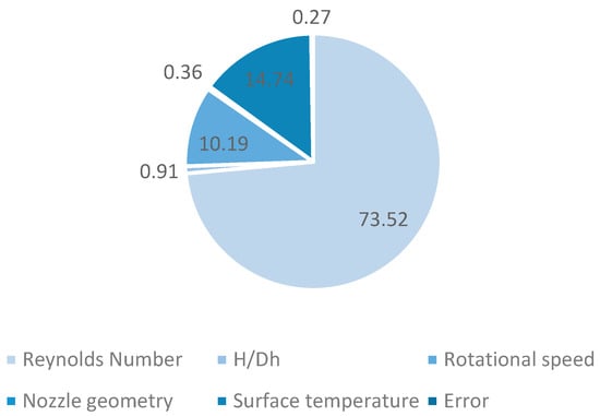
Figure 9.
Effects of parameters on the result.
The Taguchi-based optimization demonstrates that the combination of parameters yielding the highest S/N ratio corresponds to the condition with the maximum Reynolds number (7000), H/Dh = 6, Ucr = 40 rpm, moderate nozzle geometry, and Ts = 75 °C. Under these conditions, the average Nusselt number is significantly improved compared to the baseline cases.
Finally, a confirmation simulation is conducted to validate the ANOVA and Taguchi predictions. The comparison between the predicted and experimental results shows good agreement, confirming the model’s reliability. The application of the Taguchi method effectively identifies the dominant control factors, reduces experimental effort, and improves overall heat transfer performance.
As a summary, the results show that the Reynolds number is the most dominant factor, accounting for 73.52% of the total variation, while surface temperature Ts (14.74%) and rotational speed Ucr (10.19%) follow as the next most influential parameters. Conversely, H/Dh (0.91%) and nozzle geometry (0.36%) show comparatively minor effects. The low residual error (0.27%) indicates a high level of experimental reliability and repeatability.
4. Conclusions
The experimental investigation of heat transfer under jet impingement conditions considered five independent parameters: Reynolds number, jet-to-surface distance, rotational speed, nozzle geometry, and surface temperature. The Reynolds number varied across six levels, while each of the remaining parameters were studied at three levels each. The Taguchi design-of-experiments approach was implemented to reduce the number of trials while ensuring statistical robustness. In total, 18 experiments were conducted to determine the influence of each factor, and an ANOVA test was performed to evaluate their percentage contributions and significance.
The major conclusions derived from the analysis can be summarized as follows:
- The Reynolds number is the most significant factor affecting heat transfer, with a contribution of 73.52% to the overall variation. Increasing Re results in higher turbulence intensity and thinner thermal boundary layers, thereby enhancing convective heat transfer rates.
- The surface temperature exhibited the second highest impact, contributing 14.74%, confirming that higher temperature differences between the jet and surface promote stronger thermal gradients and consequently greater heat transfer.
- The rotational speed of the cylinder contributed 10.19%, showing that increased surface movement leads to improved fluid mixing and better heat transfer, though its influence is moderate compared to Re and temperature.
- The jet-to-surface distance and nozzle geometry demonstrated minor effects, contributing 0.91% and 0.36%, respectively. This outcome suggests that under the studied operating range, geometric variations have a limited impact on the average Nusselt number.
- The ANOVA results indicate that the parameters Re, surface temperature, rotational speed, and jet-to-surface distance are statistically significant (p < 0.01), whereas nozzle geometry remains less influential.
- Based on the signal-to-noise ratio analysis, the optimal conditions were determined to correspond to the highest Reynolds number, moderate jet-to-surface distance high rotational speed, and high surface temperature, ensuring a stable and efficient heat transfer configuration.
- The confirmation analysis showed good agreement between the predicted and experimental Nusselt numbers, supporting the reliability of the Taguchi model.
In summary, the Reynolds number was supported as the dominant parameter controlling the heat transfer process, followed by surface temperature and rotational speed. The Taguchi-based optimization method effectively identified these influences, minimized experimental effort, and helped to improve the accuracy and repeatability of the results. The generated data aim to support both design optimization and validation of predictive modeling frameworks, thereby contributing to the development of next-generation cooling strategies for rotating machinery components such as brake disks, turbine rollers, and motor shafts.
5. Recommendations
Future studies should extend Reynolds number and nozzle-to-cylinder distance ranges and examine the interaction between the rotational speed of the cylinder and jet exit velocity to clarify their effects on heat transfer. Additionally, a broader range of surface temperatures should be explored to better understand thermal gradient-driven enhancement.
Author Contributions
Conceptualization and methodology, G.P.; data curation, resources, formal analysis, validation, G.P. and A.S.; original draft preparation, C.K.; writing—review and editing, and project administration, N.C. All authors have read and agreed to the published version of the manuscript.
Funding
This research was funded by Inonu University, Scientific Research Projects Supporting Unit grant number [FBA-2025-4057]; APC was funded by Inonu University, Scientific Research Projects Supporting Unit.
Institutional Review Board Statement
Not applicable.
Informed Consent Statement
Not applicable.
Data Availability Statement
The data presented in this study is available on request from the corresponding author.
Acknowledgments
We would like to express our gratitude to Fırat University for providing laboratory facilities and instrumentation support.
Conflicts of Interest
The authors declare no conflicts of interest.
References
- Hussain, L.; Khan, M.M.; Masud, M.; Ahmed, F.; Rehman, Z.; Amanowicz, Ł.; Rajski, K. Heat Transfer Augmentation through Different Jet Impingement Techniques: A State-of-the-Art Review. Energies 2021, 14, 6458. [Google Scholar] [CrossRef]
- Dutta, S.; Singh, P. Opportunities in Jet-Impingement Cooling for Gas-Turbine Engines. Energies 2021, 14, 6587. [Google Scholar] [CrossRef]
- Harmand, S.; Pellé, J.; Poncet, S.; Shevchuk, I.V. Review of fluid flow and convective heat transfer within rotating disk cavities with impinging jet. Int. J. Therm. Sci. 2013, 64, 1–30. [Google Scholar] [CrossRef]
- Wang, Y.; Khayat, R.E. Impinging jet flow and hydraulic jump on a rotating disk. J. Fluid Mech. 2018, 839, 76–106. [Google Scholar] [CrossRef]
- Jeng, T.-M.; Tzeng, S.-C.; Xu, R. Heat transfer characteristics of a rotating cylinder with a lateral air impinging jet. Int. J. Heat Mass Transf. 2014, 70, 235–249. [Google Scholar] [CrossRef]
- Hammami, A. Numerical Study of Jet Impinging on a Rotating Cylinder with Heat Transfer. Comput. Therm. Sci. 2016, 8, 127–134. [Google Scholar] [CrossRef]
- Hong, S.K.; Lee, D.H.; Cho, H.H. Effect of jet direction on heat/mass transfer of rotating impingement jet. Appl. Therm. Eng. 2009, 29, 2911–2920. [Google Scholar] [CrossRef]
- Hong, S.K.; Lee, D.H.; Cho, H.H. Heat/mass transfer in rotating impingement/effusion cooling with rib turbulators. Int. J. Heat Mass Transf. 2009, 52, 5582–5593. [Google Scholar] [CrossRef]
- Minagawa, Y.; Obi, S. Development of turbulent impinging jet on a rotating disk. Int. J. Heat Fluid Flow 2004, 25, 821–829. [Google Scholar] [CrossRef]
- Popiel, C.O.; Bogusławski, L. Local Heat Transfer from a Rotating Disk in an Impinging Round Jet. J. Heat Transf. 2007, 129, 1036–1044. [Google Scholar] [CrossRef]
- Kura, T.; Wajs, J.; Fornalik-Wajs, E.; Kenjereš, S.; Gurgul, S. Thermal and Hydrodynamic Phenomena in the Stagnation Zone—Impact of the Inlet Turbulence Characteristics on the Numerical Analyses. Energies 2021, 14, 105. [Google Scholar] [CrossRef]
- Bisht, Y.S.; Pandey, S.D.; Chamoli, S. Jet impingement technique for heat transfer enhancement: Discovering future research trends. Energy Sources Part A 2023, 45, 8183–8202. [Google Scholar] [CrossRef]
- Yu, Y.; Ruan, D. Effects of Jet Impingement on Heat Transfer Characteristics of Rotating Disk. Mech. Eng. Technol. 2018, 7, 119–129. [Google Scholar] [CrossRef]
- Klinkhamer, C.; Balachandar, R.; Iyer, K.L.V. Heat transfer characteristics of a submerged jet impinging axisymmetrically onto a rotating disk. Int. J. Therm. Sci. 2025, 215, 109961. [Google Scholar] [CrossRef]
- Kistak, C.; Taskiran, A.; Celik, N. Experimental analysis of transient and steady-state heat transfer from an impinging jet to a moving plate. Heat Mass Transf. 2024, 60, 1713–1729. [Google Scholar] [CrossRef]
- Gulati, P.; Katti, V.; Prabhu, S.V. Influence of the shape of the nozzle on local heat transfer distribution between smooth flat surface and impinging air jet. Int. J. Therm. Sci. 2009, 48, 602–617. [Google Scholar] [CrossRef]
- Ahmed, Z.U.; Al-Abdeli, Y.M.; Guzzomi, F.G. Heat transfer characteristics of swirling and non-swirling impinging turbulent jets. Int. J. Heat Mass Transf. 2016, 102, 991–1003. [Google Scholar] [CrossRef]
- Lallave, J.C.; Rahman, M.M.; Kumar, A. Numerical analysis of heat transfer on a rotating disk surface under confined liquid jet impingement. Int. J. Heat Fluid Flow 2007, 28, 720–734. [Google Scholar] [CrossRef]
- Carper, H.J., Jr.; Saavedra, J.J.; Suwanprateep, T. Liquid jet impingement cooling of a rotating disk. J. Heat Transf. 1986, 108, 540–546. [Google Scholar] [CrossRef]
- Taskiran, A.; Kistak, C.; Tasar, B.; Celik, N.; Dagtekin, I. Numerical investigation and predictive modeling of heat transfer in pulsating nanofluid jets using convolutional neural networks. J. Enhanc. Heat Transf. 2025, 32, 83–105. [Google Scholar] [CrossRef]
- Kline, S.J.; McClintock, F.A. Describing Uncertainties in Single-Sample Experiments. Mech. Eng. 1953, 75, 3–8. [Google Scholar]
- Peng, X.F.; Peterson, G.P. Convective heat transfer and flow friction for water flow in microchannel structures. Int. J. Heat Mass Transf. 1996, 39, 2599–2608. [Google Scholar] [CrossRef]
- Ross, P.J. Taguchi Techniques for Quality Engineering, 2nd ed.; McGraw-Hill: New York, NY, USA, 1996. [Google Scholar]
- Tosun, N.; Cogun, C.; Tosun, G. A study on kerf and material removal rate in wire electrical discharge machining based on Taguchi method. J. Mater. Process. Technol. 2004, 152, 316–322. [Google Scholar] [CrossRef]
Disclaimer/Publisher’s Note: The statements, opinions and data contained in all publications are solely those of the individual author(s) and contributor(s) and not of MDPI and/or the editor(s). MDPI and/or the editor(s) disclaim responsibility for any injury to people or property resulting from any ideas, methods, instructions or products referred to in the content. |
© 2025 by the authors. Licensee MDPI, Basel, Switzerland. This article is an open access article distributed under the terms and conditions of the Creative Commons Attribution (CC BY) license (https://creativecommons.org/licenses/by/4.0/).