You are currently viewing a new version of our website. To view the old version click .
Applied Sciences
  • Review
  • Open Access

28 November 2025

A Review on Air and Liquid Cooling Strategies for Lithium-Ion Batteries

,
,
,
and
1
Department of Automotive Engineering, Çukurova University, Adana 01250, Turkey
2
Faculty of Mechanical Engineering and Naval Architecture, University of Zagreb, 10000 Zagreb, Croatia
*
Author to whom correspondence should be addressed.
Appl. Sci.2025, 15(23), 12617;https://doi.org/10.3390/app152312617 
(registering DOI)
This article belongs to the Special Issue Recent Advances in Transportation Machinery

Abstract

The energy that powers electric vehicles comes directly from their high-performance batteries, serving as the heart of their operation. They convert stored chemical energy into mechanical energy to propel vehicles. One of the most vital parts of an electric vehicle is a battery pack. Superior advantages such as higher energy density, longer life cycles, and the fast-charging ability of lithium-ion batteries set them apart from the others. However, battery performance and longevity exhibit a high degree of temperature sensitivity. In other words, operating batteries below and above the specified temperature range values causes problems such as decreased lifespan, safety issues, and performance losses. In electric vehicles, varying power demands during driving cause different current levels to be drawn from the battery packs. This leads to fluctuations in battery temperatures due to chemical reactions occurring. Besides that, regional and seasonal temperature variations also affect the operating temperatures of batteries. Therefore, maintaining the batteries within the specified temperature range, typically between 25 and 40 °C, is only achievable with an adequate battery thermal management system. This review intends to guide researchers working on designing more efficient thermal management systems by providing refined information about previous efforts in this field. The designs found in the literature have been illustrated with simplified figures. Cooling inlet and outlet locations are indicated in blue and red, enabling easier comparison and better understanding of different cooling designs. Air-cooling studies in the literature show that a well-designed system can keep the Tmax and ΔT values of LiB cells ~305 K and 2.8 K during 3C discharge at a Tambient of about 298.15 K. When liquid cooling systems are examined, a 50% glycol–water mixture can maintain pouch cells at nearly 30.3 °C with a ΔT of 2.78 °C under similar 3C and 25 °C conditions. Overall, the results demonstrate that well-designed BTMS configurations including optimized airflow or coolant–flow arrangements are capable of keeping LiBs safely within their optimal thermal operating conditions.

1. Introduction

Rapid economic development and industrialization have begun worldwide with the industrial revolution that emerged in the 18th and 19th centuries. During this period, human and animal labor was largely supplanted by the mechanical power provided primarily by steam engines. In the early 20th century, steam engines began to be replaced with internal combustion engines (ICEs) due to their higher efficiency, higher power-to-weight ratios, and more compact structures. The transportation sector is one of the most significant greenhouse gas contributors compared to other industries since it is dominated by ICEs that are powered mainly by conventional fossil fuels. Unfortunately, traditional fossil-based fuels have faced a depletion threat since the late 1970s and early 1980s []. Both the scarcity problems of fossil fuels and the requirement of more environmentally friendly energy sources have motivated researchers to search for electric-driven vehicles instead of fossil fuel-driven ones []. Therefore, the electrification of vehicles has become inevitable in recent years to eliminate the aforementioned problems [].
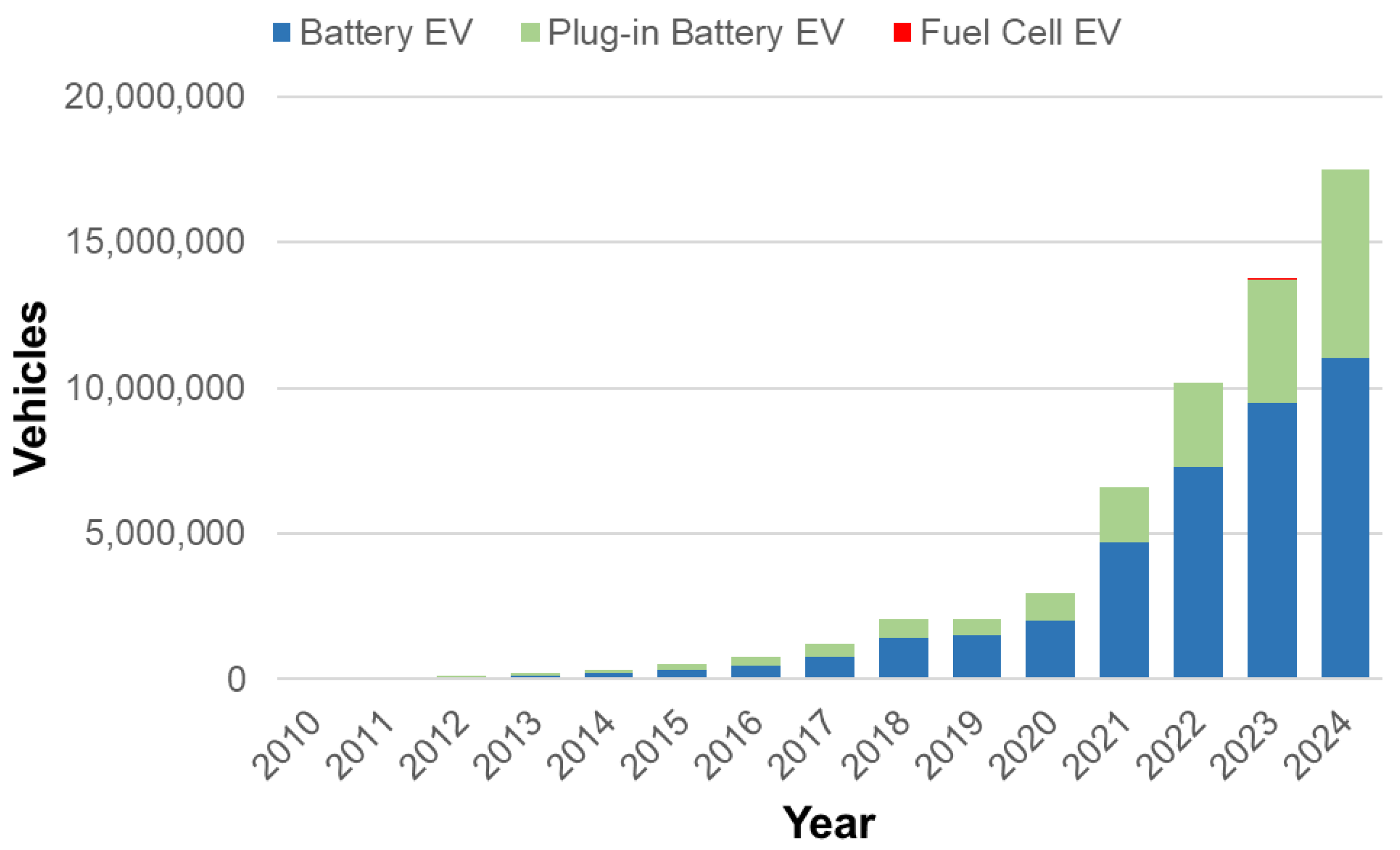
Electric vehicles (EVs) are regarded as environmentally friendly due to their ability to lower carbon emissions. Additionally, the growing concern over the finite availability of petroleum-based fuels has heightened recent interest in EVs. EVs offer not only a green solution and an alternative to conventional fuel-driven vehicles but also important advantages such as silent working and lower operational costs. Moreover, in ICEs, a significant portion of the fuel energy is lost due to thermal and frictional losses. In contrast, these losses are much lower in EVs, making them much more energy efficient [,,]. In recent years, the significant rise in EV sales worldwide, as depicted in the following Figure 1, clearly demonstrates interest in EVs. Despite this growth, particular challenges, such as developing charging infrastructures, improving battery technologies, and reducing costs, need to be overcome for more widespread utilization of EVs.
Figure 1. Electric car sales, 2010–2024 [].
Owing to their multiple advantages, lithium-ion batteries (LiBs) are widely regarded as the optimal energy storage technology for EVs. LiB demands for regions and various modes, as shown in the following Figure 2, verify this phenomenon. The figure demonstrates that the need for LiBs, which was initially centered around portable electronic applications, has expanded significantly and rapidly in the automotive sector in recent years.
In practical applications, LiBs offer higher energy density, longer life cycles, lower self-discharging, no memory effect, and fast-charging ability. However, the performance and health of LiBs are markedly affected by both storage and operational temperatures [,]. Therefore, using and storing batteries within certain temperature ranges is essential. Not only high temperatures but also low temperatures cause various problems. Lower life cycles and safety issues, such as the decomposition of electrolytes, may occur when batteries are exposed to high-temperature levels. Safety considerations constitute a critical aspect of the battery thermal management system (BTMS), particularly in systems operating under high loads or high temperatures. Thermal runaway remains one of the most serious risks, as uncontrolled heat generation can rapidly propagate between cells, leading to a fire or explosion []. Early detection methods and effective fire suppression mechanisms, including insulation barrier materials, are essential to mitigating such hazards []. In liquid-cooled architectures, coolant leakage presents an additional risk, as direct contact between conductive liquids and electrical components can lead to short circuits or system failure []. On the other hand, a lower operation temperature may cause batteries to lose capacity [,,]. As seen in the literature, the operation temperature must be held in the range of 25 °C and 40 °C. Furthermore, for optimal performance, the temperature variation (ΔT) between cells in a battery pack should be maintained below 5 °C [,,]. Implementing an efficient BTMS makes it feasible to operate the battery within these critical temperature ranges, ensuring optimal performance, extended lifespan, and enhanced safety.
Figure 2. LiB demands (a) by regions; (b) by modes, 2016–2022 [].
The BTMS is utilized to monitor and control the battery temperature. A well-designed BTMS ensures that the battery remains within optimum operation temperatures by activating heating and cooling systems in case of overcooling and overheating issues. Minimizing the variation in cell-to-cell temperature values for safety conditions and performance improvement is another significant task of BTMSs [].

2. The Motivation of Present Work

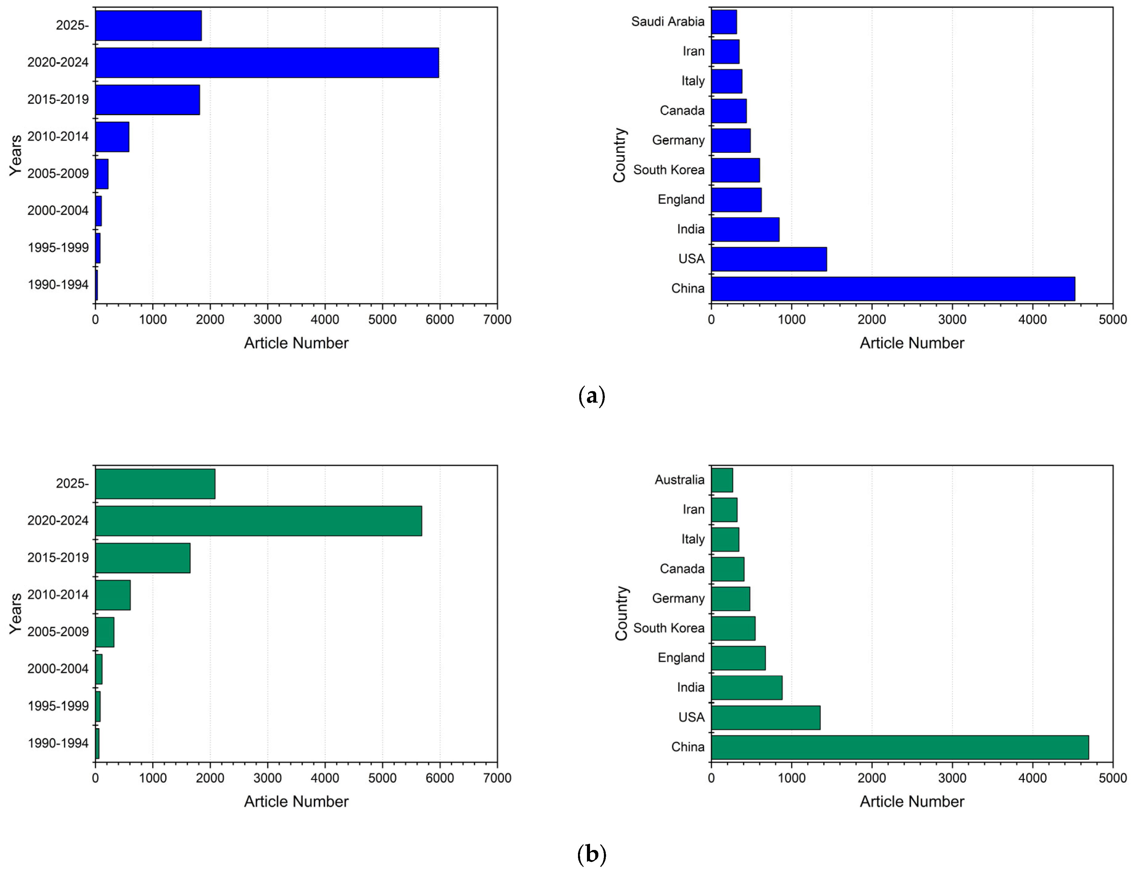
The main challenge for LiB technology, commonly employed as the principal power storage source in EVs and mobile devices, is to keep it functioning within the designated optimal temperature range. Since 1990, there has been a general increase in research on the BTMS of LiBs, and, particularly in recent times, the growth rate has escalated significantly, as evidenced in Figure 3, in parallel with the expansion of the commercial EV sector. The queries in different scientific databases were conducted with the keywords “battery thermal management system, BTMS, and battery cooling” to show significant interest in BTMS studies.
Figure 3. Articles published since 1990 and the top 10 contributing countries in the BTMS field according to (a) Web of Science; (b) Scopus database.
With the increasing number of research papers on BTMSs, it is observed that the literature also contains numerous review articles. Some of these articles cover BTMSs for LiBs generally, while others focus specifically on one or more sub-systems. Table 1 presents the details of some review articles published since 2011, along with the topics they have focused on. In previous review studies, there is no comprehensive approach addressing which parametric studies have been covered for air and liquid systems. Accordingly, this study discusses the parameters and design innovations in investigations conducted on air and liquid-based BTMSs. The novelty of this review lies in its parameter oriented and design comparative approach for both air and liquid-based BTMSs. In contrast to prior reviews, it reveals the cooling performance outcomes using quantitative metrics (Tmax, ΔT) and provides simplified schematic illustrations of the studied configurations, which offer practical design guidance for future BTMS development. In the simplified figures, inlet and outlet locations are indicated in blue and red.
Table 1. Recent review articles on BTMS.

3. Fundamentals of LiBs

A typical LiB consists of some fundamental components that achieve energy storage and release by realizing a set of chemical reactions. The basic elements of a LiB include the anode, cathode, electrolyte, separator, and current collectors. Generally, the materials such as lithium–manganese oxide ( L i M n 2 O 4 ) , lithium–nickel–manganese–cobalt oxide ( L i N i M n C o O 2 ) , lithium–iron phosphate L i F e P O 4 , lithium–cobalt oxide ( L i C o O 2 ) , and lithium–nickel–cobalt–aluminum oxide ( L i N i C o A l O 2 ) are utilized as cathode material, whereas carbon-based materials such as graphite, graphene, carbon nanowires, and carbon nanotubes are used as anode material. The conduction of L i + ions between the anode and cathode are realized through an electrolyte medium, where there is no permission for electron flow. A typical electrolyte is made of lithium-based salts such as lithium hexafluorophosphate ( L i P F 6 ) , lithium hexafluoro arsenate ( L i A s F 6 ) , lithium perchlorate ( L i C l O 4 ) , lithium tetrafluoroborate ( L i B F 4 ) , and lithium triflate ( L i C F 3 S O 3 ) dissolved in an organic carbonate such as ethylene carbonate ( C 3 H 4 O 3 ) and diethyl carbonate ( C 5 H 10 O 3 ) . The separator prevents direct contact between the anode and cathode, which could otherwise lead to a short circuit. Generally, they are produced from synthetic and natural polymers []. Conductive materials known as current collectors are situated on both the anode and cathode sides, allowing for the transfer of electrons between the battery and the external circuit.
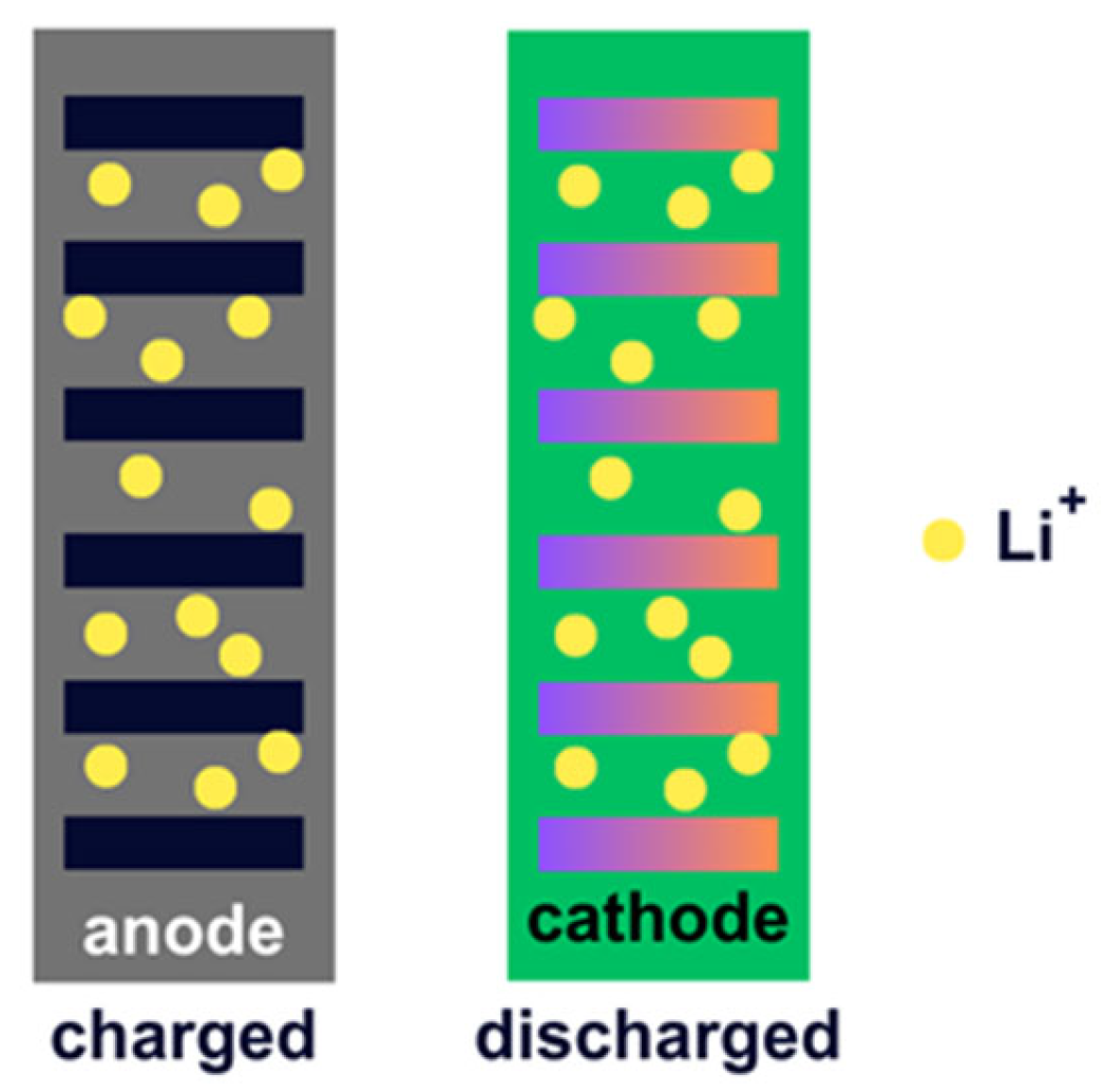
The process called intercalation occurs during the charging and discharging periods. At charged and discharged conditions, L i + ions are located between layers of the anode material and cathode material, correspondingly. Figure 4 illustrates the intercalation of L i + ions at the anode and cathode sides.
Figure 4. Intercalated Li+ ions at the anode and cathode.
Figure 5 demonstrates charge and discharge processes in more detail. Intercalated L i + ions, which are hosted in the layers of the anode material (negative electrode), start to travel toward the cathode material during discharge. On the other hand, a reverse process is realized during the charge. Currently, intercalated L i + ions, which are located in the layers of the cathode material (positive electrode), begin to go back to the anode side [].
Figure 5. Typical charge–discharge processes of LiB.
Suppose that graphite (C) is anode material and any metal oxide (M) is cathode material. The chemical reactions that occurred at the anode and cathode in a LiB while charging and discharging are given in Table 2.
Table 2. Charge and discharge reactions in a LiB [].

4. Classification of BTMSs

Throughout the development of BTMS from the past to the present, it is evident that different methods have been continuously developed each day. This situation has led to various approaches in categorizing BTMSs; however, it can be said that, in general, sub-classifications converge on common points. When the studies carried out in the field of BTMSs are examined in the literature, the BTMS classification shown in Figure 6 is considered more inclusive, as it includes all subgroups [,,].
Figure 6. BTMS classification.
Figure 6 illustrates that BTMS can be divided into three methods depending on the heat transfer medium employed: air, liquid, and PCM. PCMs differ from air and liquid-based BTMSs by offering a passive thermal regulation mechanism without an external power requirement for cooling purposes. It utilizes latent heat absorption to control cell temperature rise and enhance thermal stability []. The specific operating conditions of the battery directly influence the selection of the appropriate method. Initially, one can list factors such as operating conditions, climate, energy efficiency, safety considerations, weight and space constraints, and cost-effectiveness, as well as reliability and durability. These are pivotal in determining the most suitable BTMS for EV battery systems. Hybrid methods, combining multiple thermal management strategies, are being developed to tackle challenges encompassing all these factors in current BTMS issues. However, air and liquid-based methods remain the most frequently employed by commercial EV companies. This study focuses on the research conducted in the area, indicated by the red dash in Figure 6 and the parameters examined in these studies.
The lifespan, range, and efficiency of EVs greatly depend on maintaining the EV battery within optimal temperature ranges throughout its usage []. As rapid charging technology advances and higher-powered vehicles are introduced in the future, temperature control will become more critical than ever. Additionally, the ongoing global warming and the consequent rise in ambient temperatures (Tambient) each year may render currently used BTMSs insufficient. In this context, the development of innovative BTMS studies holds vital importance for the future of EV technology.

5. Air Cooled BTMS

In commercial applications, particularly for low power requirements, the air-cooling system is extensively recognized as a solution with demonstrated efficacy and proven success. It is crucial to implement a carefully designed configuration that maintains temperature consistency and keeps the battery pack within the desired temperature range to ensure adequate air cooling. For this reason, EV manufacturers and researchers are consistently working to optimize the design and effectiveness of these systems to boost the overall capability of EVs.
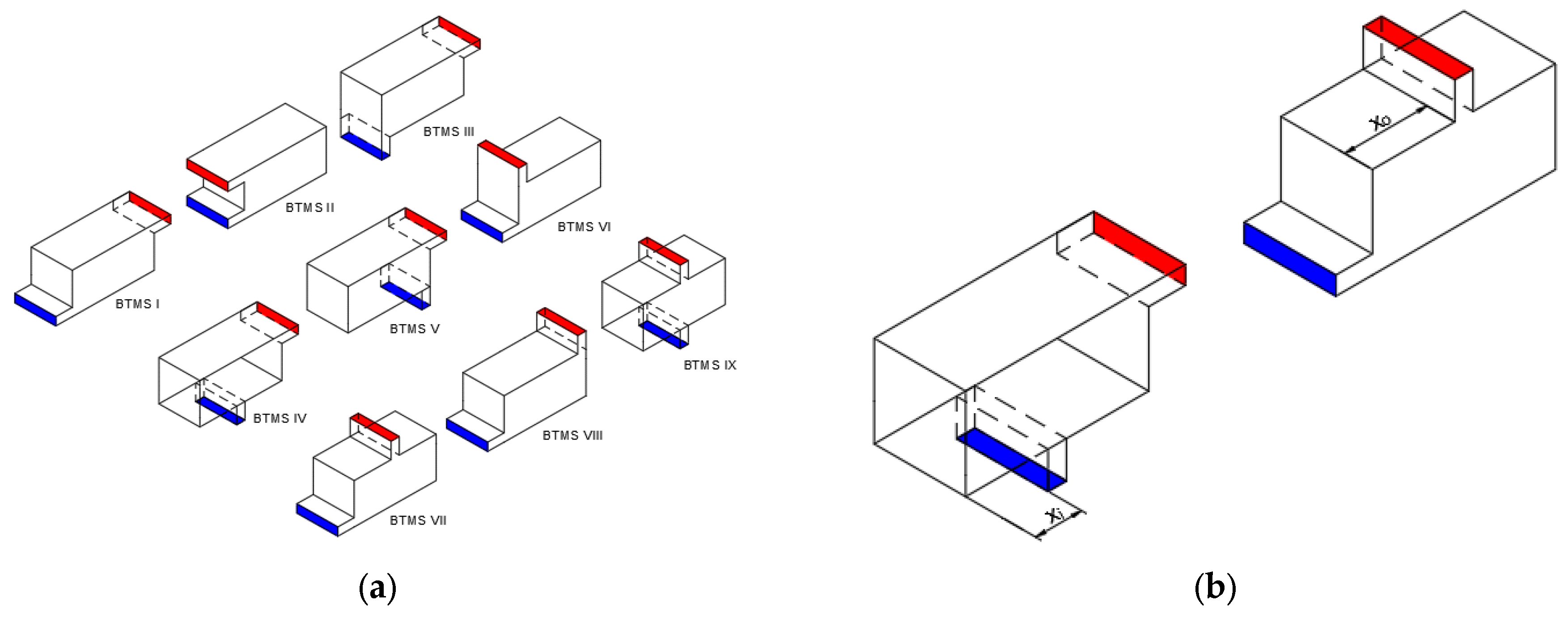
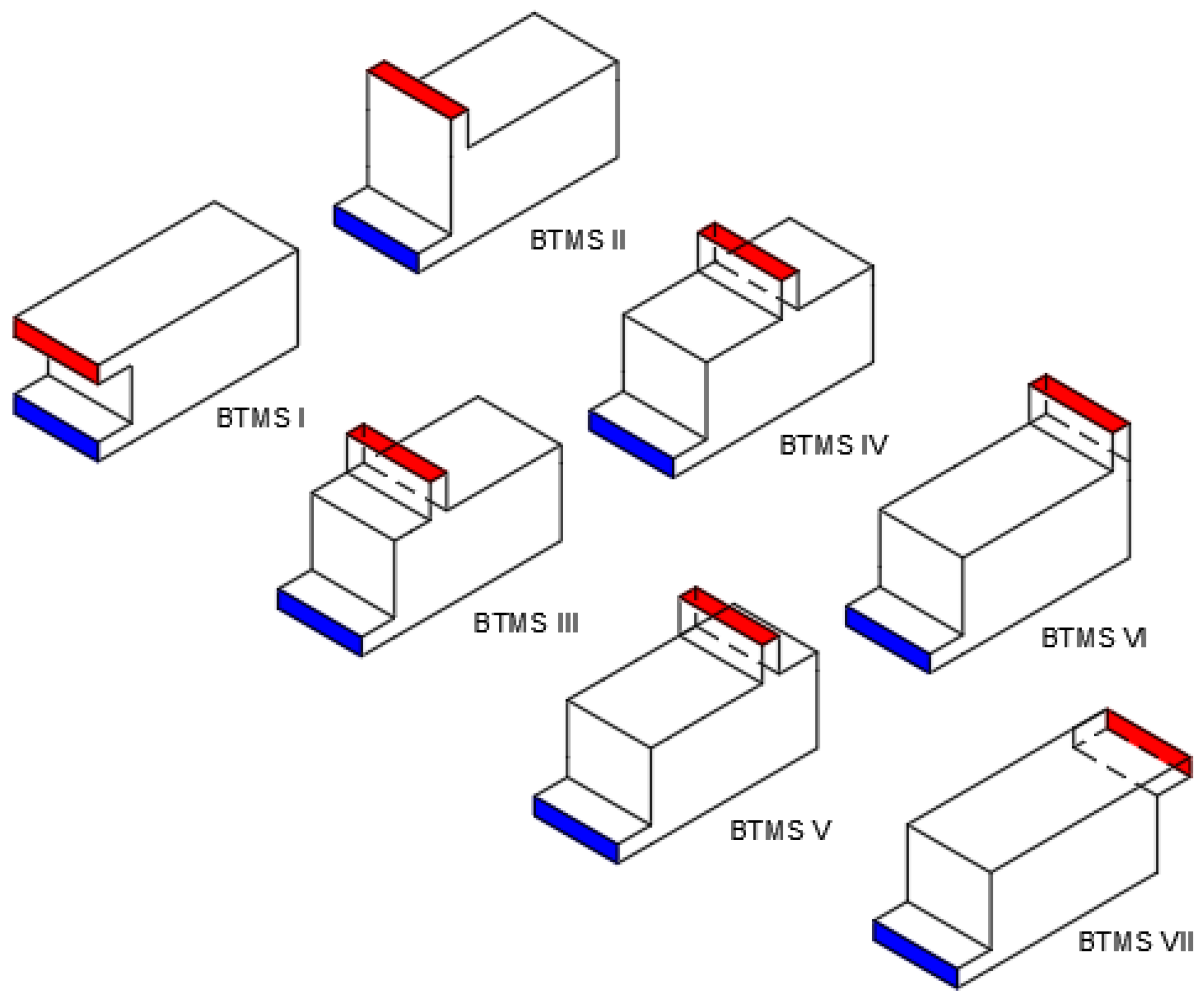
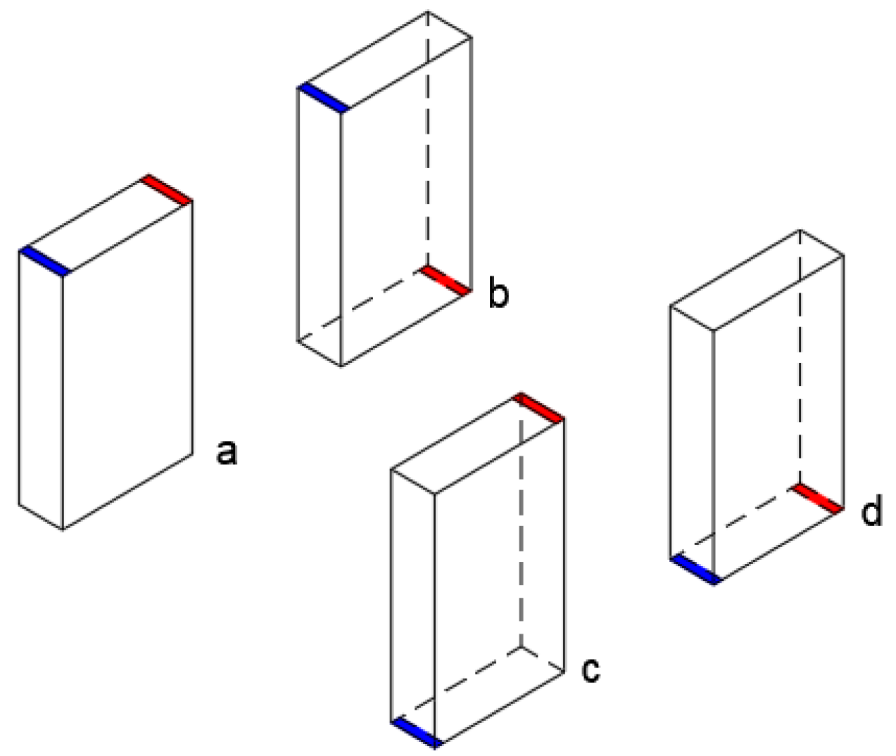
It is noteworthy that, in air-based BTMS studies, researchers often concentrate on parameters such as air pathway design, cell spacing, and battery pack configuration. In a significant portion of air-based BTMS studies, researchers have focused on the placement of ports and the influence of air at these locations on the performance of battery cooling. In an example study, Zhang et al. [] evaluated air-cooling structure effects on prismatic LiB packs to improve their cooling effectiveness. They aimed to optimize the cooling structure by altering the height and relative position of the battery pack’s inlets and outlets and adjusting cell distribution and spacing. Flow configurations are shown in Figure 7. Jiaqiang E et al. [] examined the locations of airflow inlets and outlets to determine the most efficient air-cooling pattern (Figure 8). A baffle was also utilized to enhance airflow distribution.
Figure 7. Different flow configurations (simplified representation according to []).
Figure 8. Various inlet and outlet locations (simplified representation according to []).
Park [] designed an air-cooling system for batteries and made a numerical model. The proposed design incorporated pressure relief ventilation and a tapered manifold to meet cooling performance requirements. Figure 9 illustrates the different geometrical configurations considered. They obtained acceptable cooling performance by using pressure relief ventilation and a tapered manifold with no need to change the existing battery system design.
Figure 9. Different manifold geometric configurations (simplified representation according to []).
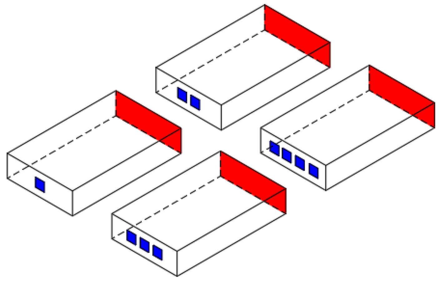
Wang et al. [] investigated forced-air cooling (FAC) for LiBs during both the charging and discharging period. Two different designs shown in Figure 10 were evaluated for effective cooling. They concluded that the proposed FAC system in their study showed effective heat dispersion under typical discharge statements, while there was a considerable accumulation of heat under fast-charge conditions.
Figure 10. Simplified view of different cooling channel designs presented in [].
Chen et al. [] sought to improve the thermal performance of an air-cooled battery pack by modifying the flow patterns through adjustments to the inlet and outlet locations (Figure 11). Cooling performance was evaluated using numerical methods, and results were validated using the experiment. Finally, an optimization strategy has been proposed to improve cooling efficiency further.
Figure 11. (a) Flow configurations; (b) location optimization of inlet and outlet (simplified representation according to []).
Widyantara et al. [] aimed to optimize the packaging design of a 74 V and 2.31 kWh LiB pack to attain the optimal operating conditions by adjusting the number of cooling fans in an air-cooled system, as illustrated in Figure 12. The findings showed that an increment in the cooling fans number minimizes the ΔT between the battery cells, and a decrease in the intake air temperature lowers the average temperature (Taverage) within the battery pack.
Figure 12. Battery pack layouts (simplified representation according to []).
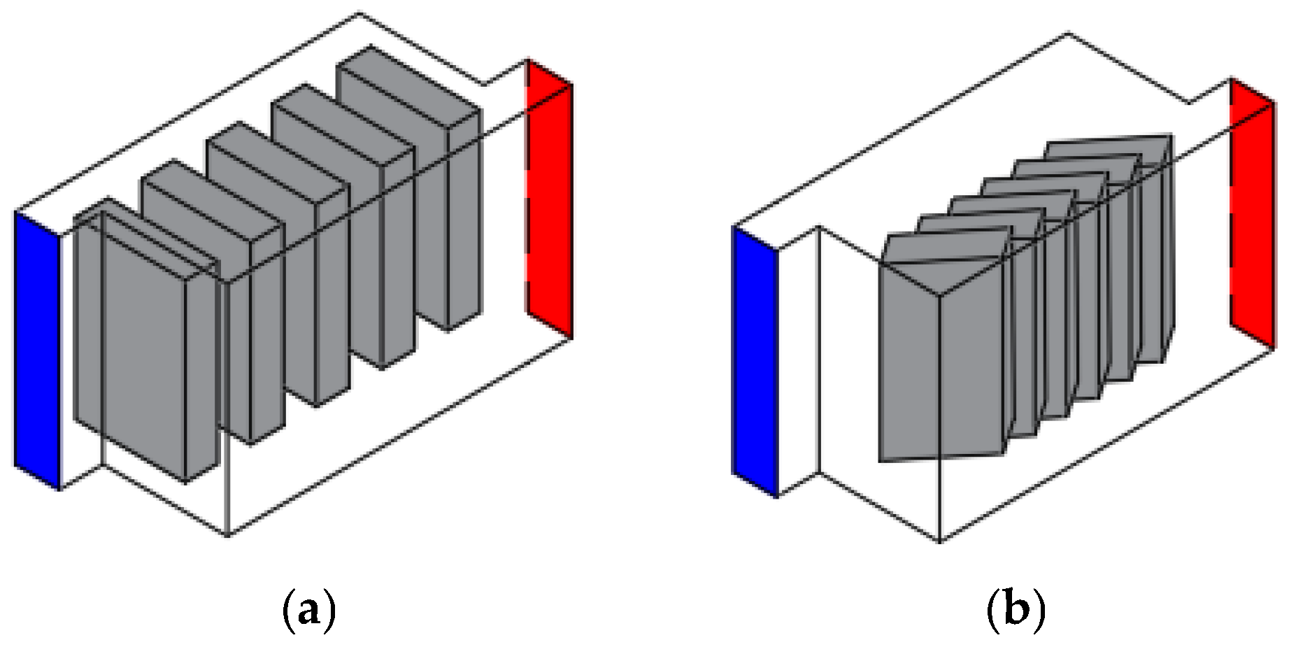
Shen et al. [] studied the thermal performance of LiFePO4 batteries by designing a modified Z-shaped air-cooled system with a non-vertical structure (Figure 13). According to the results from the study, in comparison to the conventional Z-shaped air-cooling system, the battery pack experienced a significant temperature decrease and the maximum temperature (Tmax) decreased from its initial value of 38.15 °C to 34.14 °C, representing a reduction of 10.5%. Similarly, the ΔT decreased from the original 2.59 °C to 1.97 °C, marking a decline of 23.9%.
Figure 13. (a) Conventional Z-shaped; (b) modified Z-shaped system (simplified representation according to []).
Zhao et al. [] proposed the integration of a direct evaporative cooling (DEC) system into an air-based BTMS (Figure 14). The effectiveness of the DEC system was assessed relative to air cooling and natural convection cooling techniques. Additionally, a DEC tunnel with reciprocating airflow was used to further decrease the ΔT and Tmax in the battery pack. Results show that the DEC system expands the usability of LiBs in challenging operating conditions.
Figure 14. Simplified representation of (a) 1-directional tunnel; (b) reciprocating airflow tunnel according to [].
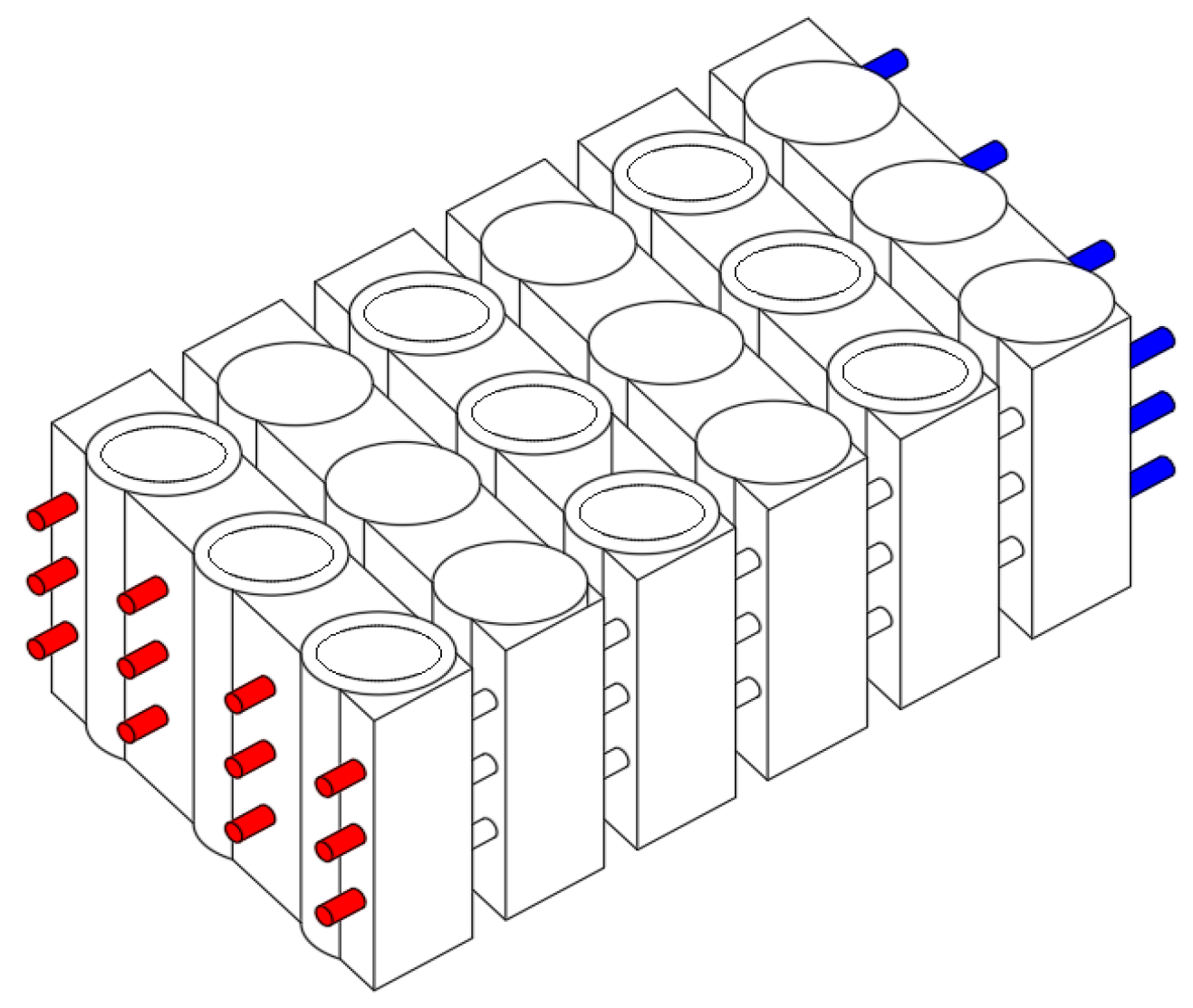
Zhang et al. [] explored the impact of different flow patterns on the cooling performance of BTMSs in their study (Figure 15). Novel BTMS designs with varied outlet positions are evaluated through numerical simulations on a 4 × 9 configuration of 21,700 batterycells. They concluded that locating the outlet at the top of the module, closer to the inlet, improves the cooling performance, and with a Z-type flow trajectory, the Taverage and Tmax of the battery packs decrease by around 3 °C when the speed of inlet wind comes to 5 m/s.
Figure 15. Flow configurations (simplified representation according to []).
The configuration of the batteries plays a crucial role in determining the effectiveness of the thermal management system. Numerous research studies have improved the cooling efficiency of air-based BTMSs by optimizing battery configurations. Zhao et al. [] developed a novel trapezoid-shaped air-cooling BTMS to enhance cooling performance while minimizing space requirements and manufacturing costs, as shown in Figure 16. They validated mathematical models for battery heat generation, heat, and mass transfer, using them to evaluate the thermal effectiveness of the innovative trapezoidal design, which incorporates an additional aluminum heat spreader. Optimal design reduces the Tmax and intercell ΔT. It has been determined that the use of a single-layer heat sink can increase the pack durability while also providing a temperature reduction of up to 4.6 K.
Figure 16. Battery pack layouts: (a) novel trapezoid; (b) conventional rectangular [].
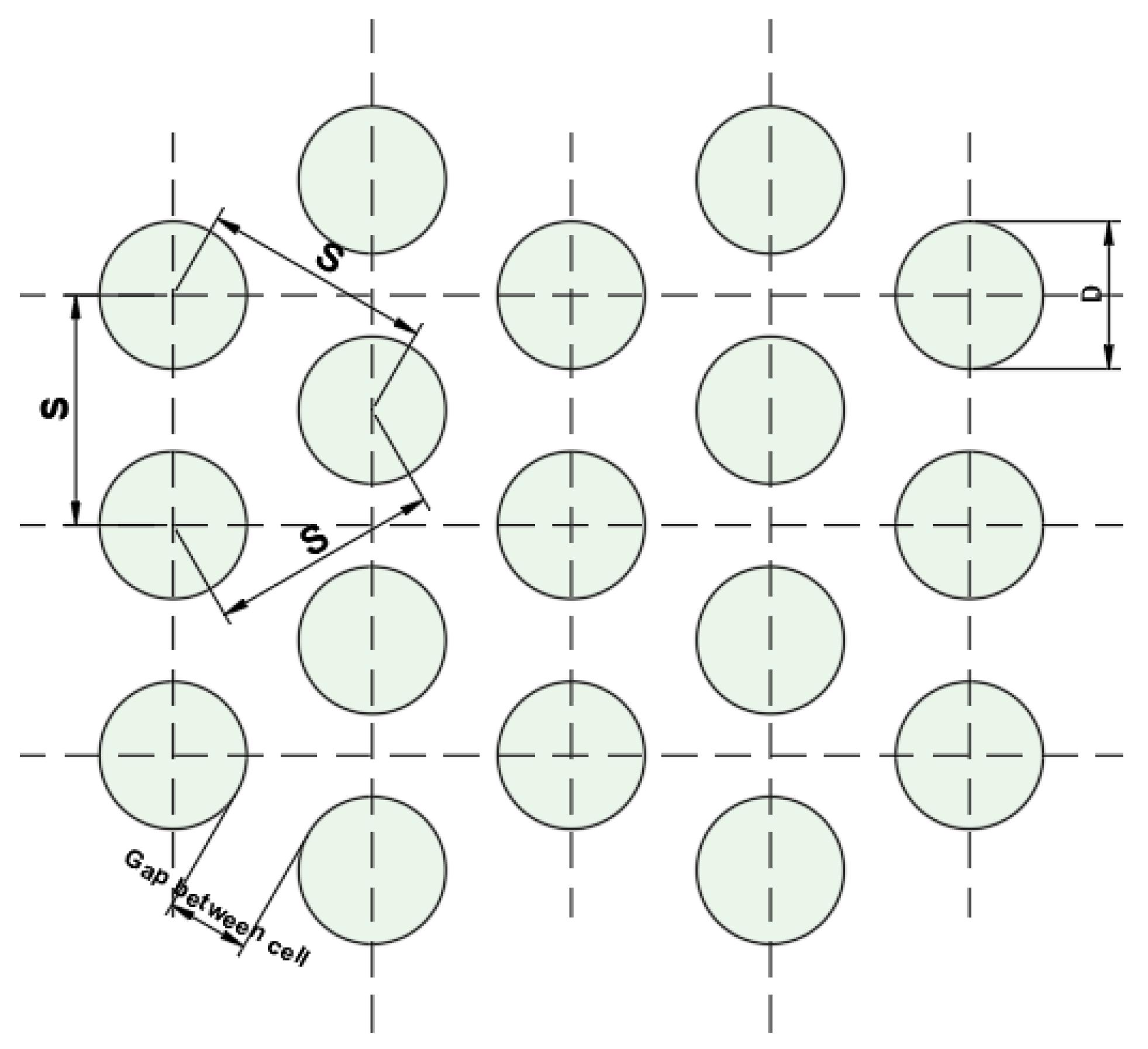
For the dimensions of gaps in the battery pack, Kirad and Chaudhari [] intended to improve the battery cooling performance by designing cell spacing in a LiB pack, as shown in Figure 17. They used FAC to thermally manage a battery pack composed of thirty cells. The longitudinal (Sl) and transverse (St) spacings between cells have been varied to observe the effects on thermal behaviors. Furthermore, they also observed the effects of flow velocity and discharge rates on cooling effectiveness to optimize the battery module.
Figure 17. Schematic of cell spacing (simplified representation according to []).
Recently, researchers have been striving to develop an optimal air-cooled BTMS by combining air pathway design with battery layout studies. The most prominent configurations among these studies are aligned, staggered, and cross structures. Jiaqiang E et al. [] investigated the heat dissipation behaviors of LiBs under different ventilation routes and various cell arrangements to reveal the best structure, as shown in Figure 18. In this study, thermal model validation was performed by building an experimental set-up. Tests were conducted at 2C and 3C discharge conditions. Experimental validation has revealed high consistency between the experimental results and the simulation outcomes.
Figure 18. Ventilation routes and cell arrangements (simplified representation according to []).
Wang et al. [] investigated various cell arrangements and FAC configurations to demonstrate the thermal characteristics of LiB modules, as given in the following Figure 19. Although the inter-cell distance was set to 1 mm in all battery modules, authors have also assessed the inter-cell spacing of the 5 × 5 rectangular configuration by changing it to 0, 0.5, 2, and 3 mm to determine the optimum value.
Figure 19. Flow configurations and cell arrangements (simplified representation according to []).
In another study, Peng et al. [] thermally investigated a LiB pack cooled with air. They also tried to determine the optimum configuration of cylindrical cells. The experiment was conducted to determine the heat characteristics of a single cell. The results were compared with the simulation. A comparison of various battery layouts, positions, and numbers of inlets and outlets was conducted to identify ideal conditions for effective cooling. All arrangements are demonstrated in Figure 20.
Figure 20. Cell arrangements and various flow configurations (simplified representation according to []).
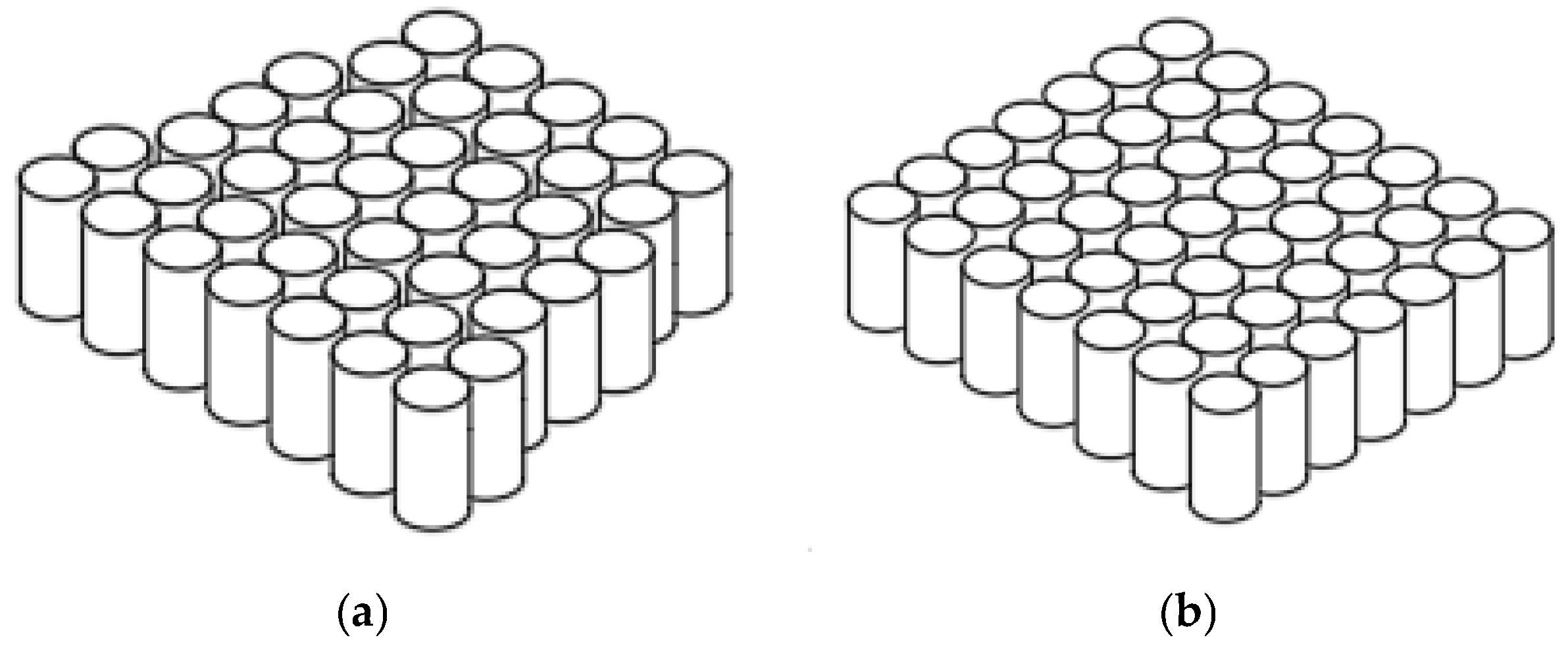
As indicated in Figure 21, Du et al. [] evaluated the air-cooled thermal management of a LiB pack with different battery arrangements, such as square, stagger, and trapezoid arrangements. They also optimized the cooling strategy by changing the location of the air inlet and the size of the air inlet and outlet.
Figure 21. Battery packs and inlet/outlet configuration (simplified representation according to []).
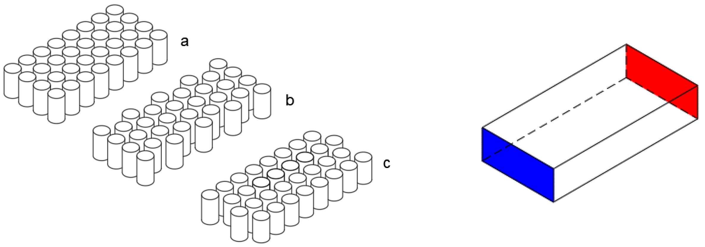
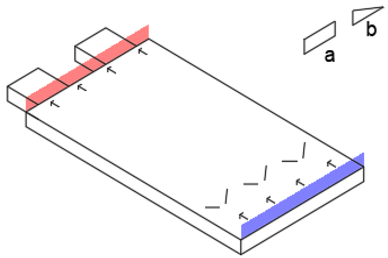
Fan et al. [] experimentally investigated the thermal characteristics of an air-cooled LiB. Approximately 18,650 type-32 cells were used in experiments. The thermal performance was evaluated for different pack designs (aligned, staggered, and cross) with various air inlet velocities. Additionally, different discharge rate values and air inlet temperatures were used to assess the system’s cooling capacity. In Figure 22 on left side, the cell arrangements (aligned, staggered, and cross) used in the study are shown, and the flow configuration is shown on the right.
Figure 22. Cell arrangements: (a) aligned, (b) staggered, and (c) cross (left) and flow configuration (right) (simplified representation according to []).
Researchers have also adopted numerical approaches in this process to shed light on experimental studies to determine the optimum values of cell spacing and air inlet–outlet positions. At this stage, in addition to the primary factors, preliminary analyses of many different designs, such as the cooling channel volume, channel angles, and flow direction modifiers like spoilers and vortex generators, can be conducted.
In one of these studies, Lu et al. [] studied the impact of cooling channel dimensions and air supply methods on the thermal performance of a staggered battery pack using a 3D numerical model. Flow strategies used in the study are shown in Figure 23. Validation of numerical results was achieved with the thermal resistance model. Firstly, the optimum cooling channel size was determined by forming gaps between cells. Then, the most appropriate inlet and outlet locations were identified to obtain optimum airflow distribution. Lastly, the cooling channel length effect on cooling performance was evaluated. A dimensionless number (L/D) was derived using the length (65 mm) and diameter (18 mm) of the battery. For the 1S14P arrangement, the L/D was 3.61, whereas it was 7.22 for the 2S14P arrangement. One of factors influencing airflow is the angle of air intake. The thermal performance of the battery pack was assessed with three parameters: Tmax, space utilization rate, and energy efficiency factor indicated with Tmax, α, and β, respectively. The definitions of α and β are given below:
α = v o l u m e   o f   c o o l i n g   c h a n n e l v o l u m e   o f   b a t t e r y   u n i t
β = h e a t   t a k e n   a w a y   b y   a i r   c o o l a n t   f r o m   a   b a t t e r y   p a c k p o w e r   c o n s u m p t i o n   f o r   s u p p l y i n g   a i r   c o o l a n t
Figure 23. Various flow strategies for cooling (a) top inlet-outlet (b) top inlet-bottom outlet (c) bottom inlet-top outlet (d) bottom inlet-outlet (simplified representation according to []).
Xie et al. [] intended to enhance the design of the LiB pack cooled by a forced-air BTMS. Through simulations and experiments, as depicted in Figure 24, the impact of varying air inlet/outlet angles and the flow channel width between cells is being evaluated. They have also optimized the structural parameters with single-factor analysis and orthogonal test methods. In addition, efforts have included the implementation of passive flow methods to achieve a more even temperature distribution. In one of these studies, Zhang et al. [] proposed a new model to investigate the effects of the spoiler number and placement in an air-cooling system (Figure 25). Enhancing cooling efficiency was achieved by modifying the angle and height of the spoiler, which led to reductions in Tmax and ΔTs. The study revealed that placing spoilers within the distribution plenum and cooling channel significantly improved the heat dissipation performance of the battery pack. Nevertheless, it was observed that the optimized design resulted in a 5.78 Pa increase in pressure drop loss compared to the original model.
Figure 24. Pack structure (simplified representation according to []).
Figure 25. Battery pack layout (simplified representation according to []).
Zhou et al. [] developed an innovative air-cooling approach using the air distribution pipes inside the battery module and conducted numerical simulations and experimental tests to examine the thermal performance and airflow within this strategy. Their investigation focused on how changes in orifice parameters, inlet pressure, and discharge rate affect cooling effectiveness, as shown in Figure 26. They concluded that increasing the orifice diameter and number of rows results in reduced Tmax, improved temperature uniformity, and a minimal increase in power consumption.
Figure 26. Simplified representation of air distribution pipe with 3 orifices from [].
Xie et al. [] investigated the thermal behavior and cooling effects of two types of vortex generators (VG) to assess their heat transfer performance (Figure 27). Both types enhanced heat transfer before the generators, but only the delta winglet VG continued to improve the heat transfer after the generators by effectively mixing cold and hot airflow. The heat transfer improvement was attributed to the mixing of fluid, modification of the boundary layer, and destabilization of flow by the VGs. In the results of the study, the delta winglet VG demonstrated superior performance in reducing the Tmax of the pouch cell and increasing the local Nusselt number compared to the rectangular rib VG at a discharge rate of 5 C.
Figure 27. Flow domain representation with (a) rectangular and (b) delta winglet [].
Details of reviewed studies using air-cooled BTMSs are given in Table 3.
Table 3. Details of studies using an air-cooled BTMS (* represents Taverage).

6. Liquid-Cooled BTMS

Even though air cooling systems are simpler and cheaper, they are not compelling enough to keep the batteries in the desired temperature range, especially for EV batteries. Liquid cooling systems can absorb significantly more heat than air cooling systems, making them essential for managing the thermal demands of high-capacity batteries. Liquid cooling, with its higher heat transfer coefficient, offers greater efficiency than air cooling [].
Liquid cooling systems are categorized as direct or indirect based on whether the coolant directly contacts the battery surface []. Heat transfer fluids (HTFs) are used for direct systems, and these systems usually have the advantage of higher cooling rates than air and indirect liquid cooling systems. The cooling liquids circulate in a tube or metal plate and do not contact the battery systems directly when an indirect system is used []. The efficiency of liquid cooling systems is influenced by various parameters related to the system’s design and operating conditions.
In this section, a review of various liquid-cooled systems was conducted. It was seen that many of the liquid-cooled BTMSs have mainly focused on channel design, coolant flow type, and cooling plate configurations for the determination of the liquid cooling system performance.
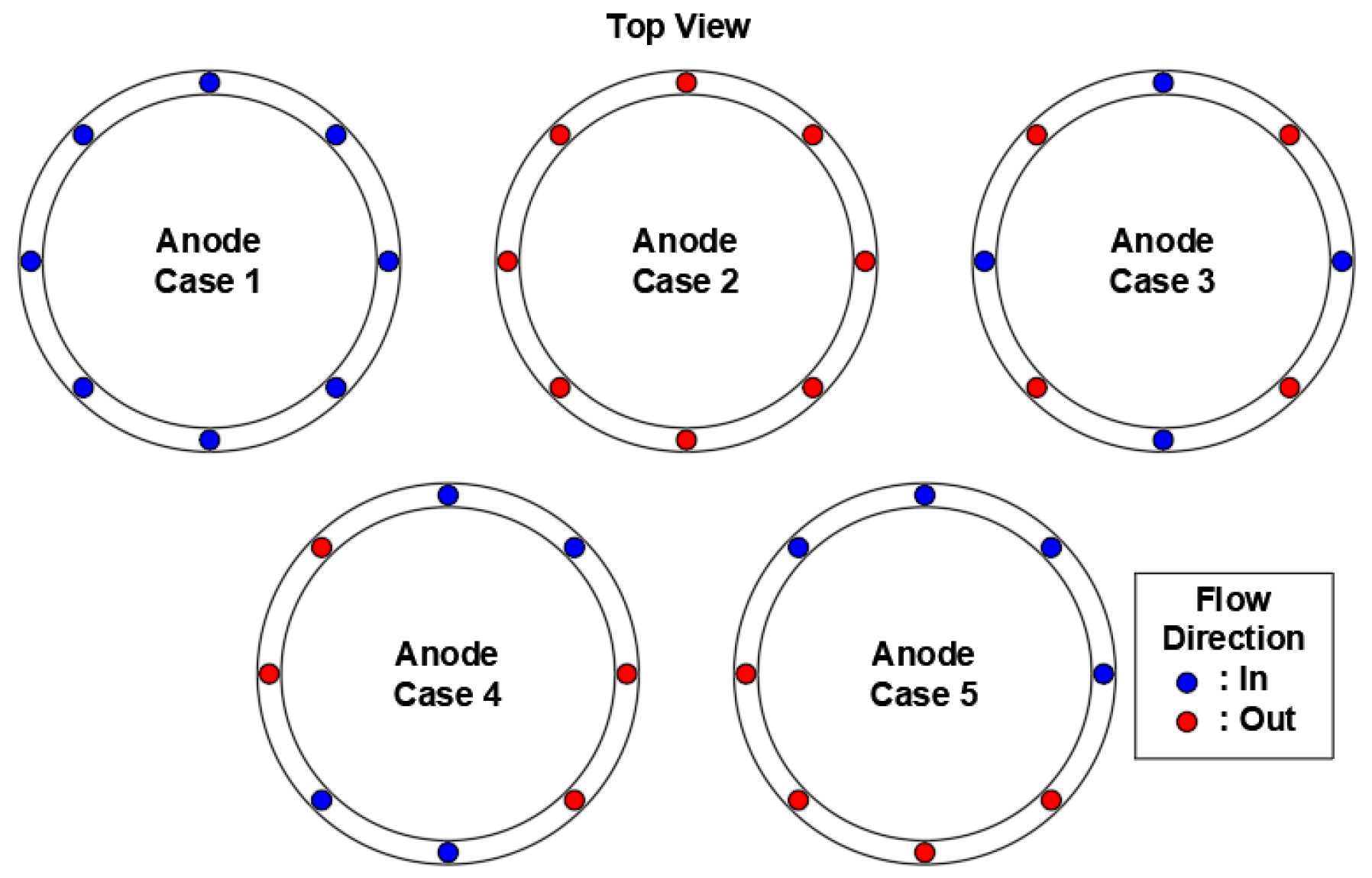
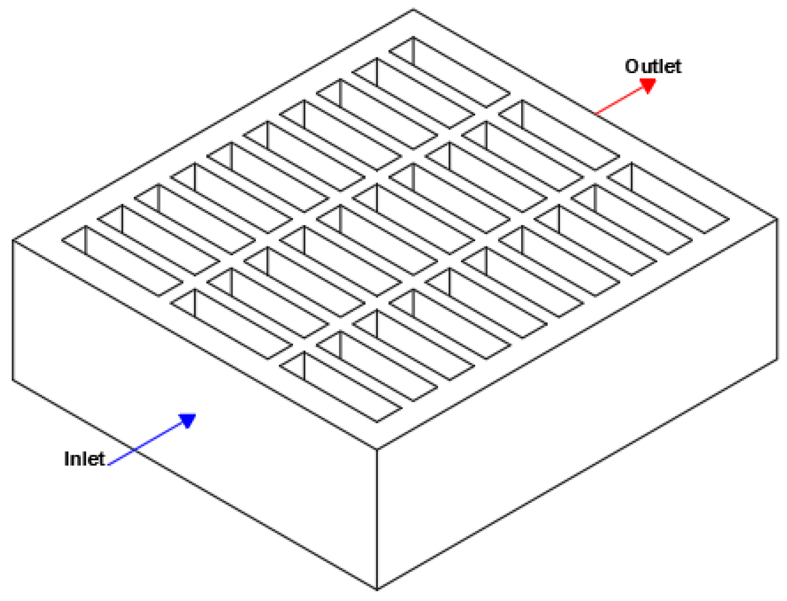
Channel design for liquid cooling systems plays a vital role in BTMS. Zhao et al. [] numerically investigated the effect of different parameters on a battery pack’s Tmax and local ΔT. The related investigation focused on the mini-channel design for the pack, as shown in Figure 28, and used aluminum material. The findings indicated that, by having an inlet mass flow rate of 1 × 10⁻³ kg/s and at least four mini-channels, the Tmax of batteries can successfully maintain below 40 °C. In another study utilizing a mini-channel design, Du et al. [] conducted an experimental study to evaluate the thermal performance of a liquid cooling system for a battery module across different cooling configurations. Three other cases were considered, and water was used as a coolant in the study.
Figure 28. Schematic of different flow directions (simplified representation according to []).
Figure 29 shows the schematic representation of the cooling systems. It was observed that the mini-channel cooling system efficiently reduced both the Taverage and ΔT within the battery module. With the implementation of cooling case 1, the Taverage decreased by 43.7% at 1 C and 47.3% at 1.5 C, while the ΔT reduced by 65.9% at 1 C and 63.6% at 1.5 C.
Figure 29. The diagram of the battery module featuring the mini-channel liquid cooling system (simplified representation according to []).
Gao et al. [] proposed a novel BTMS design by implementing gradient channels along the flow direction within a cylindrical LiB module, as shown in Figure 30. The numerical research involved optimizing the number of segments and the combination of their lengths.
Figure 30. Schematic diagrams of different channel designs (a) ULCD; (b) USCD; (c) GDC; and (d) 2-segment, 3-segment, and 4-segment GDC (simplified representation according to []).
The best-performing configuration was found to be a two-segment gradient channel design (GCD) (with lengths Lf = 60 mm and Lr = 120 mm), which effectively reduced both the Tmax and ΔT within the battery module. In comparison to Uniform Small Channel Design (USCD) and Uniform Large Channel Design (ULCD), the ideal two-segment GCD demonstrated a remarkable 79.2% and 60.2% reduction in ΔT, respectively.
A three-dimensional transient simulation model for a liquid-cooled BTMS was developed by Li et al. []. This system was designed for pouch LiBs and included spiral channel cooling plates and flow distributors. It has been noted that the dual flow distributor achieves superior flow uniformity compared to the multi-series flow distributor. As a result of the studies, the best cooling performance was found for case 1 (spiral channel), and it was obtained at a flow rate of 1.2 g.s−1 with a channel length of 1116.65, a width of 6, a height of 6 mm, and a coolant temperature of 31 °C. Additionally, the study found that positioning the channel outlet and inlet on opposite sides of the cooling plate effectively lowered the Tmax of the battery module.
Liu et al. [] investigated the multi-parameters’ effects on the ΔTmax of the battery, the Tmax, and the average pressure drop. Among these parameters include the channel angle (α), channel width (D), channel number (N), and inlet flow rate (M) of the cooling plate (Figure 31). The orthogonal test analysis revealed that the primary factors influencing cooling performance were D and M, with N and α considered as secondary factors. Additionally, it was found that even during 3C discharging, Tmax could be maintained at 33.34 °C. Optimum parameter results obtained by combining the orthogonal test and non-dominated sorting genetic algorithm-II (NSGA-II) are as follows: D = 2.60 mm, M = 0.10 m/s, N = 15, and α = 159°.
Figure 31. Geometry of the liquid cooling system according to [].
Another crucial parameter to focus on alongside the channel design is the cooling plate design. Rao et al. [] studied the thermal characteristics of a liquid BTMS with an adjustable interface for a lithium-ion battery module. The researchers changed the length of the aluminum block in contact with the battery between 12 and 24 mm in accordance with the BTMS. Figure 32 illustrates the cooling system for the battery module. The simulations displayed that the increment of the aluminum block length decreased both the Tmax and ΔT between the cells of the battery module. The authors also incorporated inlet velocity as a parameter and observed that elevated inlet velocities led to a reduction in both the Tmax and the ΔT among the cells. However, they also noted that increasing the inlet velocity leads to an increase in pump power consumption.
Figure 32. Schematic representation of the liquid cooling system of the battery module according to [].
Zhang et al. [] studied the addition of flexible graphite to the structure of liquid heat exchange that was designed with a flat tube bank with aluminum material, as indicated in Figure 33. The authors discovered that incorporating flexible graphite into the battery pack structure enhanced temperature uniformity. With the introduction of flexible graphite into the structure, the ΔT on the battery surface decreased from 7 °C to 2 °C.
Figure 33. The battery pack design: (a) battery cell structure details; (b) battery cell cooling structure (simplified representation according to []).
Xu et al. [] investigated a battery module featuring a unique liquid-cooled shell structure thermal management, as illustrated in Figure 34. The module, containing 4 × 5 cylindrical batteries, is housed within an aluminum shell with multiple flow channels. The authors documented that the battery module exhibited a Tmax of 26.85 °C, 30.42 °C, and 36.21 °C at discharge rates of 1 C, 2 C, and 3 C, respectively. A low flow velocity within the range of 0.3 to 0.5 m/s proved to be adequate in fulfilling the temperature criteria under typical operational conditions. They also showed that using different busbar connections minimizes the occurrence of hot spots and lowers the overall temperature.
Figure 34. Illustration of developed liquid-cooled shell battery module according to [].
Wang et al. [] examined the cooling performance of a thermal silica-based BTMS for prismatic LiBs. To evaluate the effectiveness of their BTMS design, the authors tested different configurations of cooling channels, including variations in quantity, flow rates, and directions, through both experiments and simulations. Figure 35 illustrates the cooling design schematically. The authors found out that, with the increment of thermal silica plate and liquid channels, the Tmax of the battery decreases. Furthermore, the direction of flow had no significant impact on the cooling performance, while an increase in the inlet flow rate improved the overall effectiveness of the BTMS. The authors concluded that the optimum inlet flow rate for their specific design was 0.25 m/s for the 5 C-rate discharge, and a 0.1 m/s flow rate was sufficient for the 3 C-rate discharge.
Figure 35. Schematic of cooling system with 5 channels (simplified representation according to []).
Xu et al. [] examined the impact of various factors, including the discharge rate, inlet temperature, flow rate, arrangement of cooling plates, and type of liquid cooling system on the Tmax, temperature uniformity, cooling efficiency, and overall heat transfer behavior of these cooling systems, as shown in Figure 36. Designating the F2 type as the most effective liquid cooling system, it was observed that the optimal inlet temperature is 18.75 °C. Additionally, the inlet flow rates should be no less than 6 l/min for 1 C discharges and 12 l/min for 2 C discharges.
Figure 36. Schematics of plate designs: (a) F1-roll-bond liquid cooling plate; (b) F2-roll-bond liquid cooling plate; (c) F3-roll-bond liquid cooling plate; and (d) Z-roll-bond liquid cooling plate (simplified representation according to []).
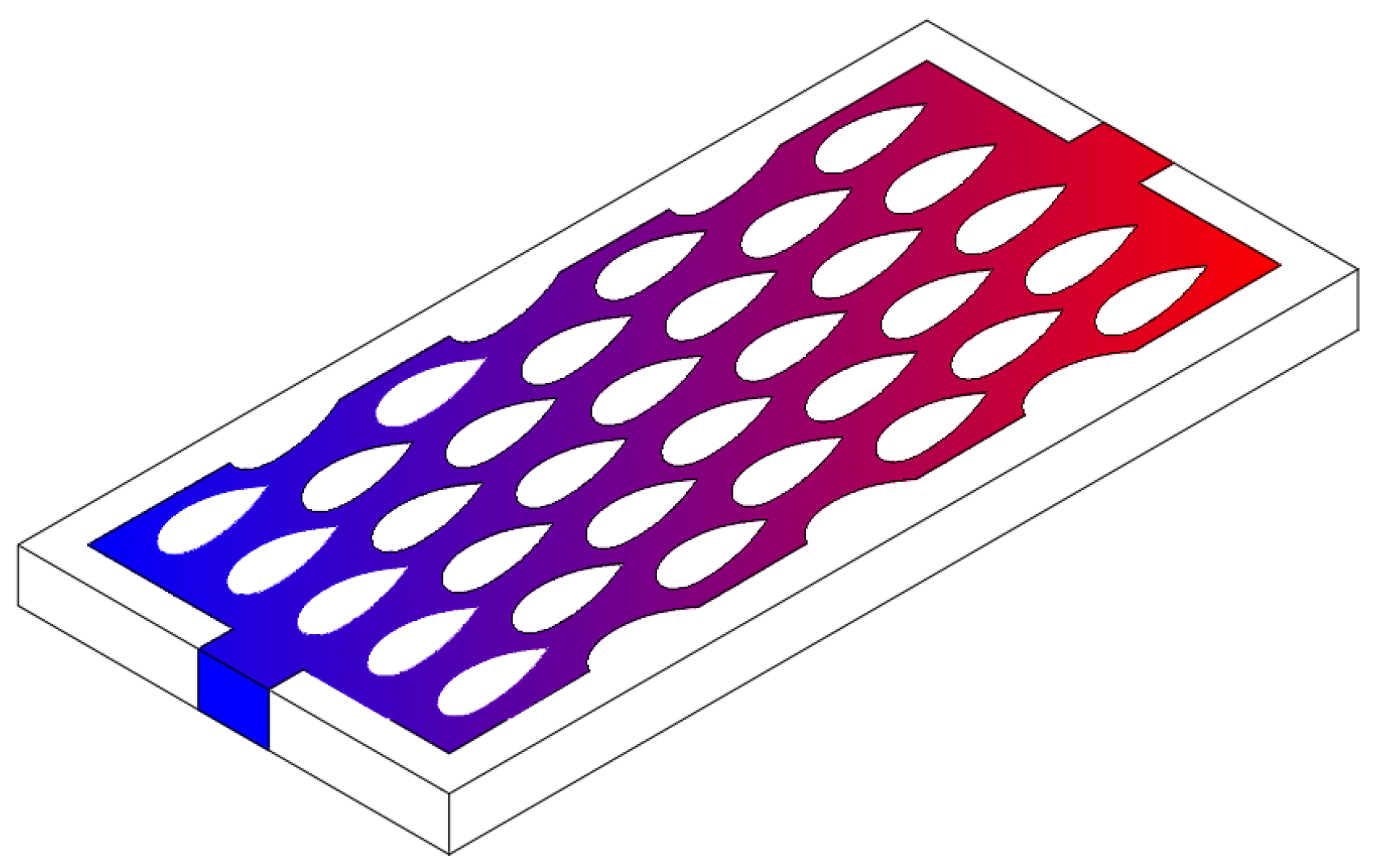
Zhao et al. [] performed an extensive numerical analysis focusing on the thermal management of liquid cooling plates featuring drop-shaped deflectors, as depicted in Figure 37. They introduced three variants of liquid cooling plates with mesh structures (LCP-MSs) and conducted a comparative assessment against a conventional liquid cooling plate with straight channels (LCP-SC).
Figure 37. Schematic diagram of drop-shaped liquid cooling plate [].
The findings revealed that LCP-MSs were effective in improving temperature uniformity within LiBs while mitigating heat concentration. Of the three LCP-MS variants, the LCP with drop-shaped deflectors (LCP-DD) distinguished itself by its capacity to reduce the coolant pressure drop (Δp) while upholding a comparable cooling performance. The study concluded with a determinative finding, establishing that the ΔTmax, Tmax, and Δp could be regulated at 3.1 K, 301.3 K, and 251 Pa, respectively.
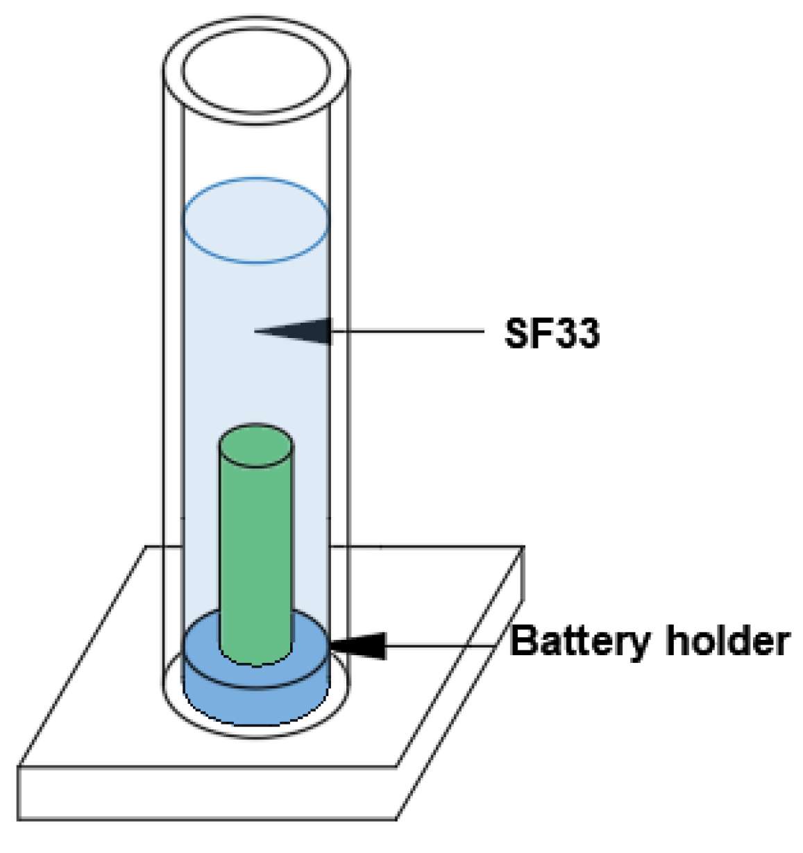
Creating a new design to maintain the batteries at optimal temperature levels can sometimes be encountered as both a financial and time loss. However, as an alternative, changing the type of coolant is a parameter considered to prevent these issues and keep batteries at the desired temperature. A study that can be regarded as a simple method was conducted by Li et al. []. The visual representation of the study has been provided in Figure 38. The researchers examined both liquid immersion cooling and FAC methods applied to LiB 18,650 cells across various conditions, including discharge rates of 2 C, 4 C, and dynamic load scenarios. In this study, the battery immersed in fluorinated liquid (SF33) gave better results than FAC at all load conditions and the temperature levels required for the battery to work efficiently. During the discharge process, FAC experiences a Tmax increase of 14.06 °C, whereas the SF33 immersion cooling results in a temperature rise of 4.97 °C.
Figure 38. SF33 immersion cooling method used in [].
In a more advanced study, Park and Jung [] investigated the impact of the battery cell configuration and the type of HTF on parasitic power consumption and the cooling performance of the system. The battery cells in the battery module were directly cooled by mineral oil. They found that narrower battery modules with smaller gaps exhibit lower power consumption because of reduced coolant flow rates in contrast to wider modules with larger gaps. Nevertheless, wider modules with larger gaps are favored when the goal is to minimize cell-to-cell variation (Figure 39).
Figure 39. Schematic illustration of the battery array according to [].
In addition to changing the cooling fluid, there are also promising studies that involve the addition of different types of nanoparticles to the used fluid. One of these studies was conducted by Tousi et al. []. They conducted an exploration in pursuit of an innovative BTMS incorporating silver (II) oxide (AgO) nanofluid, specifically tailored for 18,650/21,700 lithium-ion batteries. The primary objective was to sustain the ideal temperature levels and uniformity throughout the battery pack. The design of the battery pack is shown in Figure 40. The incorporation of AgO nanofluid within the battery pack’s channels served to diminish the highest temperature and mitigate temperature fluctuations. The thermal performance of the battery pack saw significant improvement when the number of 21,700-type LiBs was reduced from 12 to 7. When utilizing the suggested liquid cooling system with optimal fluid flow parameters and subjecting it to a high discharge C-rate (7 C), the Tmax can be effectively regulated to stay below 33.5 °C, with a corresponding ΔT of just 0.67 °C. Yetik and Karakoc [] numerically examined BTMS for 15 prismatic LiB cells with alumina (Al2O3) nanofluid. Al2O3, used as nanoparticles, has been added to the coolant water at concentrations of 3% and 5%. The conclusions showed that, under the conditions of an inlet velocity of 0.04 m/s and an inlet temperature of 300 K, all C values remained within safe operating temperatures with a 5% volume fraction. However, a discharge rate of 5C, combined with a 3% volume fraction (except when the inlet speed was maintained at 0.04 m/s and the inlet temperature was reduced to 295 K), led to the exceedance of the safe operating temperature.
Figure 40. Geometry of battery pack (simplified representation according to []).
In another numerical study conducted by Yetik and Karakoc [], iron (III) oxide (Fe2O3) nanoparticles were used at concentrations of 3%, 4%, and 6%, with water (H2O) and engine oil (EO) used as the coolant fluids. When comparing refrigerants, nanofluid cooling maintained temperatures at approximately 310 K, with better results observed when Fe2O3 was added to H2O rather than EO. However, at a 6% nanofluid ratio, the Tmax change for EO, better than water, was 1.15 K. In addition, lower C values resulted in a more uniform distribution of temperature. The cooling area for the battery pack is given in Figure 41.
Figure 41. Illustration of the cooling area for the prismatic battery module according to [].
Besides the main topics discussed above, there are also studies that directly influence coolant flow and thereby indirectly impact thermal management. As an example, Xie et al. [] conducted numerical research on a micro-channel liquid cooling BTMS for EV battery modules. The battery module of the Tesla Model S was simulated using the developed coupled model, as indicated in Figure 42. The results showed that incorporating baffles led to a more uniform temperature distribution within the battery module. Simulations have been conducted for four different heights and six different positions. As the height of the baffles increased, there was a corresponding increase in Δp, while the ΔT and Tmax decreased. In all simulation results, ΔT maintained below 5 K, and Tmax remained below 304 K. Details of reviewed studies using liquid-cooled BTMSs are given in Table 4.
Figure 42. (a) Configuration of a liquid cooling lithium battery pack; (b) structure of the baffle (simplified representation according to []).
Table 4. Details of studies using liquid-cooled BTMSs (* represents Tliquid and # represents Taverage).

7. Discussion and Conclusions

Today, EVs are continuously used under challenging operating conditions. Due to regional and seasonal variations, operating temperatures can vary significantly. These temperature fluctuations can pose specific issues for the LiBs of EVs. Therefore, BTMSs that can maintain low or high-temperature conditions at an optimum level are essential.
It is clear that cooling batteries is of great importance for optimal battery performance, lifespan, and safety issues. In this study, a comprehensive evaluation of air and liquid BTMSs was conducted in order to reveal various design considerations, since researchers mostly prefer air and liquid cooling techniques to remove excessive heat from the battery pack. In both techniques, design parameters such as fluid velocity, cell arrangement, number and location of inlets and outlets for flowing fluid, etc., are very crucial for the effectiveness of cooling. It is not surprising that scientists have performed many parametric studies to determine the optimum design for BTMSs.

7.1. Air-Cooled BTMSs

Thermal techniques, categorized into three main groups, air, liquid, and PCM cooling, have been the subject of research and development by researchers and vehicle manufacturers for a long time. Controlling battery temperature through either natural or forced-air cooling is still considered the most preferred method. Air-cooled BTMSs have been notably characterized by their extensive investigation of parameters encompassing airway design, battery layout, and inter-battery spacing. In this regard, the impact of different designs and parameters has been examined through data related to the Tmax within the battery pack and ΔTs between cells. It has been observed in these studies that, in contrast to natural convection, fan-assisted forced-convection cooling systems are more effective, representing a fundamental and economically valid choice among BTMSs. Within these studies, airflow designs with inlet and outlet configurations placed reciprocally have been investigated, along with using unidirectional airflow. Those incorporating reciprocal airflow patterns have demonstrated reduced ΔTs between cells among these designs. Various airflow channel designs resembling letters such as J, T, U, and Z have also been explored for reciprocal airflow configurations. The U-shaped battery module was found to minimize ΔTs between cells, while the J-shaped module achieved the lowest battery temperature. Furthermore, the addition of flow directors to the airflow channels, aimed at reducing the pressure drop, was observed to enhance performance.
Regarding the parameter of inter-cell spacing, studies have concluded that the lowest Tmax was achieved with irregular cell arrangements, while spacing based on arithmetic ratios exhibited the best performance in terms of ΔTs between cells. Additionally, concerning cell arrangements, predominantly regular, cross, and aligned arrangements were examined, and it was determined that the cross arrangement outperformed the others in terms of minimum temperature and ΔTs between cells. In conclusion, the studies indicate that BTMS employing air-cooling strategies is effective in maintaining safe operating conditions for battery packs at low discharge rates but may prove insufficient at high discharge rates or in conditions of elevated Tambient. Lately, recent research has shifted towards hybrid cooling system investigations, incorporating liquid or PCM alongside air to address these challenges.
In the literature, along with experimental studies on BTMS, there has been a notable increase in numerical investigations, particularly in parametric studies, in recent years. Various battery models have been used to create battery packs, and different discharge rates, air velocities, and other design parameters have been analyzed through numerical approaches. In this way, the opportunity to examine many different designs that can guide experimental studies has emerged. It has been observed that the Fluent module in the Ansys software package is mainly used in numerical studies. Within this module, the Newman, Tiedemann, Gu, and Kim (NTGK) battery model has emerged as the most preferred electrochemical sub-model due to its requirement for fewer parameters and its simplicity in calculations. The NTGK model generally possesses a semi-experimental character and necessitates discharge data to determine coefficient values. These numerical studies have become a valuable tool for optimizing the design and performance of BTMSs, influencing the direction of experimental studies.
Air-based BTMSs offer several distinct advantages. Design simplicity, the absence of coolant fluids, and reduced maintenance requirements contribute to their cost-effectiveness. The lightweight nature of air-cooling systems makes them advantageous for applications where weight constraints are critical. Nonetheless, an air-based BTMS comes with specific drawbacks. Their cooling capacity is relatively limited, particularly when addressing batteries with high energy or high power densities, which could potentially result in thermal management complexities. On the other hand, achieving optimal airflow and temperature distribution within a battery pack can be challenging, necessitating sophisticated design and control algorithms. Despite these limitations, the prospects of air BTMSs remain promising, subject to ongoing technological advancements addressing these shortcomings.

7.2. Liquid-Cooled BTMSs

Liquid-cooled BTMSs have started to be the first preference in cases of high thermal loads, where high-capacity batteries are used for high-power demanding systems. Particularly, the EVs that have been emerging in the last decade require stabilized thermal management systems for reliable usage. Liquid-cooled systems are superior to air-cooled systems because they offer higher cooling effectiveness and more stable thermal conditions. The liquid-cooled BTMSs are categorized as direct or indirect based on the contact of the thermal fluids with the battery. The effectiveness of the liquid cooling system depends on some parameters, such as cooling channel design, cooling plate configurations, and coolant fluid type.
In the literature, numerous experimental and numerical investigations have been dedicated to examining diverse channel designs, cooling plate configurations, and various coolant fluid options. These studies have shown that increasing the area affecting the battery, whether by increasing the length or number of cooling fluid channels, as well as by increasing the plate’s length or altering its design, is effective in enhancing the stability of cooling. However, it is important to note that such enhancements come at the cost of increased complexity and expenses for indirect cooling systems. While most of the studies are focused on indirect cooling, there are a few studies related to direct cooling systems. Even though direct cooling is more effective than indirect systems, the current studies indicate that those systems are relatively less reliable. Due to problematic issues such as leakage and short-circuiting caused by direct cooling, more efforts are required for applications.
Along with the various channel designs and plate configurations, the inlet liquid parameters such as temperature and flow rate have been proven to be critical parameters for maintaining the batteries under a specific temperature and keeping cell ΔTs low. The liquid type, which directly alters the heat transfer coefficient, is an important parameter considering dielectric properties and low pumping power. Water has been more commonly used as a coolant than mineral oil, glycol, and engine oil. In particular, the use of various nanoparticles such as alumina (Al2O3) and iron (III) oxide (Fe2O3) to enhance the thermal conductivity of the coolant has also gained attention. The small size and high surface area of nanoparticles offer a notable advantage in improving heat transfer within a thermal management system. When nanoparticles are evenly distributed in cooling fluids, they enable more efficient heat dissipation, effectively ensuring protection against battery overheating.
Similarly, with air-cooled BTMSs, numerical studies have shown a remarkable increase in the analysis of the liquid-cooled BTMSs with various studies. In addition to the Fluent module in the Ansys software package, the COMSOL Multiphysics Simulation program has been utilized. By using COMSOL Multiphysics, engineers, and researchers can perform detailed numerical simulations to design and optimize BTMSs, taking into account various factors like heat generation, heat dissipation, and safety measures. This aids in developing more reliable and efficient systems, which is particularly important in applications like electric vehicles. In a liquid-cooled BTMS, orthogonal testing methods are also employed to further minimize the number of experiments needed alongside software packages. The objective is to identify the most influential factors and their optimal levels for achieving the desired outcomes. Using the orthogonal test method, a relatively small number of experiments can provide valuable insights into the system’s behavior and the interaction of different parameters. This method is precious for complex systems like the BTMS, where multiple variables, such as coolant flow rate, coolant temperature, and material properties, can affect the BTMS’s thermal performance. Through such numerical studies, the BTMS can be made to operate more effectively under desired operating conditions.
These numerical and optimization-based insights help contextualize the thermal performance outcomes reported in experimental air and liquid-cooled BTMS studies. Air-cooling studies in the literature show that a well-designed system can keep the Tmax and ΔT values of LiB cells ~305 K and 2.8 K during 3C discharge at a Tambient of about 298.15 K. When liquid cooling systems are examined, a 50% glycol–water mixture can maintain pouch cells at nearly 30.3 °C with ΔT of 2.78 °C under similar 3C and 25 °C conditions. Overall, the results demonstrate that well-designed BTMS configurations including optimized airflow or coolant–flow arrangements are capable of keeping LiBs safely within their optimal thermal operating conditions.
Building upon these performance observations, Table 5 presents a qualitative design matrix comparing air and liquid-cooled BTMSs based on performance trends reported in the reviewed literature. The dot-based rating reflects a qualitative synthesis of findings across the selected studies. A higher dot count corresponds to a better performance for the respective criterion.
Table 5. Design matrix for air vs. liquid battery thermal management systems.

8. Future Prospects

The primary focus of the industry has shifted towards advanced batteries with higher energy and power densities, an increased capacity, and rapid charging capabilities, addressing the major drawbacks of current electric vehicles, namely range and charging times. Attaining these objectives necessitates the inevitable development of thermal management systems capable of effectively mitigating serious thermal issues. Furthermore, when considering the environmental temperature fluctuations resulting from global warming, the importance of adaptable BTMSs tailored to different conditions becomes paramount. In this context, research endeavors aiming to enhance system capabilities by combining active/passive heating–cooling methods, thermoelectric approaches, and primary methods such as air, liquid, and PCM offer promise for the future. Additionally, integrating machine learning and AI-supported controllers into BTMSs is expected to enhance system efficiency and safety. It is worth noting that there is a limited number of works in the literature concerning Hybrid BTMSs and AI-controlled BTMS fields.
While this review mainly focused on the thermal performance of air and liquid-based BTMS designs, it is also important to recognize that scalability and manufacturability strongly influence their suitability for real EV applications. Packaging space, coolant routing, power demand for fans or pumps, pressure drop, cost, and maintenance needs may all affect large-scale implementation. Therefore, future research should address not only improvements in Tmax and ΔT but also the engineering and production challenges that determine whether these BTMS concepts can be adopted in commercial EV battery packs or not.
Another important aspect that should also be considered in future BTMS evaluations is system safety. Especially, the risks associated with coolant leakage and electrical insulation in liquid-cooled configurations. Including safety-related factors together with thermal performance metrics will enable more comprehensive BTMS comparisons for commercial applications.
Future studies should also investigate the cost and economic feasibility of air and liquid-based BTMS technologies to support large-scale EV implementation. While thermal performance remains essential, factors such as system cost, component availability, maintenance requirements, and long-term operational expenses will determine whether these cooling strategies can be realistically adopted in commercial battery packs. Integrating economic assessments with thermal performance evaluations will be an important direction for future BTMS research.

Author Contributions

Conceptualization, E.T., P.I. and S.K.; writing—original draft preparation, E.T., P.I., S.K. and A.C.Y.; writing—review and editing, E.T., S.K., A.C.Y. and M.O.; supervision, M.O. All authors have read and agreed to the published version of the manuscript.

Funding

This research was supported by Çukurova University Scientific Research Project FBA-2022-15234.

Institutional Review Board Statement

Not applicable.

Data Availability Statement

No new data were created or analyzed in this study. Data sharing is not applicable to this article.

Conflicts of Interest

The authors declare no conflicts of interest.

Abbreviations

The following abbreviations are used in this manuscript:
EVElectric vehicle
BTMSBattery thermal management system
DECDirect evaporative cooling
FACForced air cooling
GCDGradient channel design
HTFsHeat transfer fluids
ICEInternal combustion engines
LCP-DDLiquid cooling plates with drop-shaped deflectors
LCP-MSsLiquid cooling plates with mesh structures
LCP-SCLiquid cooling plates with mesh structures
LiBLithium-ion batteries
NSGA-IINon-dominated sorting genetic algorithm-II
PCMPhase change material
VGVortex generators
ULCDUniform large channel design

References

  1. Tüccar, G.; Tosun, E.; Özgür, T.; Aydın, K. Diesel Engine Emissions and Performance from Blends of Citrus Sinensis Biodiesel and Diesel Fuel. Fuel 2014, 132, 7–11. [Google Scholar] [CrossRef]
  2. Jaguemont, J.; Van Mierlo, J. A Comprehensive Review of Future Thermal Management Systems for Battery-Electrified Vehicles. J. Energy Storage 2020, 31, 101551. [Google Scholar] [CrossRef]
  3. Kumar, R.R.; Alok, K. Adoption of Electric Vehicle: A Literature Review and Prospects for Sustainability. J. Clean. Prod. 2020, 253, 119911. [Google Scholar] [CrossRef]
  4. Rao, Z.; Qian, Z.; Kuang, Y.; Li, Y. Thermal Performance of Liquid Cooling Based Thermal Management System for Cylindrical Lithium-Ion Battery Module with Variable Contact Surface. Appl. Therm. Eng. 2017, 123, 1514–1522. [Google Scholar] [CrossRef]
  5. Zhang, L.; Chen, Q.; Wang, T. Effects of Air Cooling Structure on Cooling Performance Enhancement of Prismatic Lithium-ion Battery Packs Based on Coupled Electrochemical-thermal Model. Energy Sci. Eng. 2021, 9, 1450–1464. [Google Scholar] [CrossRef]
  6. Tie, S.F.; Tan, C.W. A Review of Energy Sources and Energy Management System in Electric Vehicles. Renew. Sustain. Energy Rev. 2013, 20, 82–102. [Google Scholar] [CrossRef]
  7. International Energy Agency (IEA). Global EV Data Explorer—Data Tools—IEA. Available online: https://www.iea.org/data-and-statistics/data-tools/global-ev-data-explorer (accessed on 21 June 2025).
  8. Lu, M.; Zhang, X.; Ji, J.; Xu, X.; Zhang, Y. Research Progress on Power Battery Cooling Technology for Electric Vehicles. J. Energy Storage 2020, 27, 101155. [Google Scholar] [CrossRef]
  9. Sharma, D.K.; Prabhakar, A. A Review on Air Cooled and Air Centric Hybrid Thermal Management Techniques for Li-Ion Battery Packs in Electric Vehicles. J. Energy Storage 2021, 41, 102885. [Google Scholar] [CrossRef]
  10. ELJarray, O.; Dai, H.; Chen, Z.; Raja, S.V.; Li, B.; Cao, S.; Sun, S.; Zhang, G. Ensuring Battery Safety in Electric Vehicles: Challenges, Developments, and Future Perspectives. Small 2025, e2503406. [Google Scholar] [CrossRef]
  11. Ghiji, M.; Novozhilov, V.; Moinuddin, K.; Joseph, P.; Burch, I.; Suendermann, B.; Gamble, G. A Review of Lithium-Ion Battery Fire Suppression. Energies 2020, 13, 5117. [Google Scholar] [CrossRef]
  12. Behi, H.; Gandoman, F.H.; Karimi, D.; Hosen, M.S.; Behi, M.; Jaguemont, J.; Van Mierlo, J.; Berecibar, M. Thermal Management of the Li-Ion Batteries to Improve the Performance of the Electric Vehicles Applications. In Modern Automotive Electrical Systems; Wiley: Hoboken, NJ, USA, 2022; pp. 149–191. [Google Scholar]
  13. Akinlabi, A.A.H.; Solyali, D. Configuration, Design, and Optimization of Air-Cooled Battery Thermal Management System for Electric Vehicles: A Review. Renew. Sustain. Energy Rev. 2020, 125, 109815. [Google Scholar] [CrossRef]
  14. Basu, S.; Hariharan, K.S.; Kolake, S.M.; Song, T.; Sohn, D.K.; Yeo, T. Coupled Electrochemical Thermal Modelling of a Novel Li-Ion Battery Pack Thermal Management System. Appl. Energy 2016, 181, 1–13. [Google Scholar] [CrossRef]
  15. Saw, L.H.; Ye, Y.; Tay, A.A.O.; Chong, W.T.; Kuan, S.H.; Yew, M.C. Computational Fluid Dynamic and Thermal Analysis of Lithium-Ion Battery Pack with Air Cooling. Appl. Energy 2016, 177, 783–792. [Google Scholar] [CrossRef]
  16. Zhao, C.; Cao, W.; Dong, T.; Jiang, F. Thermal Behavior Study of Discharging/Charging Cylindrical Lithium-Ion Battery Module Cooled by Channeled Liquid Flow. Int. J. Heat Mass Transf. 2018, 120, 751–762. [Google Scholar] [CrossRef]
  17. Liu, Y.; Ouyang, C.; Jiang, Q.; Liang, B. Design and Parametric Optimization of Thermal Management of Lithium-Ion Battery Module with Reciprocating Air-Flow. J. Cent. South Univ. 2015, 22, 3970–3976. [Google Scholar] [CrossRef]
  18. International Energy Agency (IEA). Trends in Batteries—Global EV Outlook 2023—Analysis—IEA. Available online: https://www.iea.org/reports/global-ev-outlook-2023/trends-in-batteries (accessed on 21 June 2025).
  19. Park, S.; Jung, D. Battery Cell Arrangement and Heat Transfer Fluid Effects on the Parasitic Power Consumption and the Cell Temperature Distribution in a Hybrid Electric Vehicle. J. Power Sources 2013, 227, 191–198. [Google Scholar] [CrossRef]
  20. Rao, Z.; Wang, S. A Review of Power Battery Thermal Energy Management. Renew. Sustain. Energy Rev. 2011, 15, 4554–4571. [Google Scholar] [CrossRef]
  21. Wang, Q.; Jiang, B.; Li, B.; Yan, Y. A Critical Review of Thermal Management Models and Solutions of Lithium-Ion Batteries for the Development of Pure Electric Vehicles. Renew. Sustain. Energy Rev. 2016, 64, 106–128. [Google Scholar] [CrossRef]
  22. Xia, G.; Cao, L.; Bi, G. A Review on Battery Thermal Management in Electric Vehicle Application. J. Power Sources 2017, 367, 90–105. [Google Scholar] [CrossRef]
  23. Wu, W.; Wang, S.; Wu, W.; Chen, K.; Hong, S.; Lai, Y. A Critical Review of Battery Thermal Performance and Liquid Based Battery Thermal Management. Energy Convers. Manag. 2019, 182, 262–281. [Google Scholar] [CrossRef]
  24. Wu, S.; Xiong, R.; Li, H.; Nian, V.; Ma, S. The State of the Art on Preheating Lithium-Ion Batteries in Cold Weather. J. Energy Storage 2020, 27, 101059. [Google Scholar] [CrossRef]
  25. Patel, J.R.; Rathod, M.K. Recent Developments in the Passive and Hybrid Thermal Management Techniques of Lithium-Ion Batteries. J. Power Sources 2020, 480, 228820. [Google Scholar] [CrossRef]
  26. Buidin, T.I.C.; Mariasiu, F. Battery Thermal Management Systems: Current Status and Design Approach of Cooling Technologies. Energies 2021, 14, 4879. [Google Scholar] [CrossRef]
  27. Abdelkareem, M.A.; Maghrabie, H.M.; Abo-Khalil, A.G.; Adhari, O.H.K.; Sayed, E.T.; Radwan, A.; Rezk, H.; Jouhara, H.; Olabi, A.G. Thermal Management Systems Based on Heat Pipes for Batteries in EVs/HEVs. J. Energy Storage 2022, 51, 104384. [Google Scholar] [CrossRef]
  28. Olabi, A.G.; Maghrabie, H.M.; Adhari, O.H.K.; Sayed, E.T.; Yousef, B.A.A.; Salameh, T.; Kamil, M.; Abdelkareem, M.A. Battery Thermal Management Systems: Recent Progress and Challenges. Int. J. Thermofluids 2022, 15, 100171. [Google Scholar] [CrossRef]
  29. Kumar Thakur, A.; Sathyamurthy, R.; Velraj, R.; Saidur, R.; Pandey, A.K.; Ma, Z.; Singh, P.; Hazra, S.K.; Wafa Sharshir, S.; Prabakaran, R.; et al. A State-of-the Art Review on Advancing Battery Thermal Management Systems for Fast-Charging. Appl. Therm. Eng. 2023, 226, 120303. [Google Scholar] [CrossRef]
  30. Torabi, F.; Ahmadi, P. Front Matter. In Simulation of Battery Systems; Elsevier: Amsterdam, The Netherlands, 2020; pp. i–iii. ISBN 9780128162125. [Google Scholar]
  31. Tete, P.R.; Gupta, M.M.; Joshi, S.S. Developments in Battery Thermal Management Systems for Electric Vehicles: A Technical Review. J. Energy Storage 2021, 35, 102255. [Google Scholar] [CrossRef]
  32. Liu, L.; Zhang, X.; Lin, X. Recent Developments of Thermal Management Strategies for Lithium-Ion Batteries: A State-of-The-Art Review. Energy Technol. 2022, 10, 2101135. [Google Scholar] [CrossRef]
  33. Jiang, Z.Y.; Li, H.B.; Qu, Z.G.; Zhang, J.F. Recent Progress in Lithium-Ion Battery Thermal Management for a Wide Range of Temperature and Abuse Conditions. Int. J. Hydrog. Energy 2022, 47, 9428–9459. [Google Scholar] [CrossRef]
  34. Afaynou, I.; Faraji, H.; Choukairy, K.; Djebali, R.; Rezk, H. Comprehensive Analysis and Thermo-Economic Optimization of a Hybrid Phase Change Material-Based Heat Sink for Electronics Cooling. Heat. Transf. 2025, 54, 3754–3774. [Google Scholar] [CrossRef]
  35. Shahjalal, M.; Shams, T.; Islam, M.E.; Alam, W.; Modak, M.; Hossain, S.B.; Ramadesigan, V.; Ahmed, M.R.; Ahmed, H.; Iqbal, A. A Review of Thermal Management for Li-Ion Batteries: Prospects, Challenges, and Issues. J. Energy Storage 2021, 39, 102518. [Google Scholar] [CrossRef]
  36. E, J.; Yue, M.; Chen, J.; Zhu, H.; Deng, Y.; Zhu, Y.; Zhang, F.; Wen, M.; Zhang, B.; Kang, S. Effects of the Different Air Cooling Strategies on Cooling Performance of a Lithium-Ion Battery Module with Baffle. Appl. Therm. Eng. 2018, 144, 231–241. [Google Scholar] [CrossRef]
  37. Park, H. A Design of Air Flow Configuration for Cooling Lithium Ion Battery in Hybrid Electric Vehicles. J. Power Sources 2013, 239, 30–36. [Google Scholar] [CrossRef]
  38. Wang, Y.-W.; Jiang, J.-M.; Chung, Y.-H.; Chen, W.-C.; Shu, C.-M. Forced-Air Cooling System for Large-Scale Lithium-Ion Battery Modules during Charge and Discharge Processes. J. Therm. Anal. Calorim. 2019, 135, 2891–2901. [Google Scholar] [CrossRef]
  39. Chen, K.; Wu, W.; Yuan, F.; Chen, L.; Wang, S. Cooling Efficiency Improvement of Air-Cooled Battery Thermal Management System through Designing the Flow Pattern. Energy 2019, 167, 781–790. [Google Scholar] [CrossRef]
  40. Widyantara, R.D.; Naufal, M.A.; Sambegoro, P.L.; Nurprasetio, I.P.; Triawan, F.; Djamari, D.W.; Nandiyanto, A.B.D.; Budiman, B.A.; Aziz, M. Low-Cost Air-Cooling System Optimization on Battery Pack of Electric Vehicle. Energies 2021, 14, 7954. [Google Scholar] [CrossRef]
  41. Shen, X.; Cai, T.; He, C.; Yang, Y.; Chen, M. Thermal Analysis of Modified Z-Shaped Air-Cooled Battery Thermal Management System for Electric Vehicles. J. Energy Storage 2023, 58, 106356. [Google Scholar] [CrossRef]
  42. Zhao, R.; Liu, J.; Gu, J.; Zhai, L.; Ma, F. Experimental Study of a Direct Evaporative Cooling Approach for Li-ion Battery Thermal Management. Int. J. Energy Res. 2020, 44, 6660–6673. [Google Scholar] [CrossRef]
  43. Zhang, S.-B.; He, X.; Long, N.-C.; Shen, Y.-J.; Gao, Q. Improving the Air-Cooling Performance for Lithium-Ion Battery Packs by Changing the Air Flow Pattern. Appl. Therm. Eng. 2023, 221, 119825. [Google Scholar] [CrossRef]
  44. Zhao, G.; Wang, X.; Negnevitsky, M.; Zhang, H.; Li, C. Performance Improvement of a Novel Trapezoid Air-Cooling Battery Thermal Management System for Electric Vehicles. Sustainability 2022, 14, 4975. [Google Scholar] [CrossRef]
  45. Kirad, K.; Chaudhari, M. Design of Cell Spacing in Lithium-Ion Battery Module for Improvement in Cooling Performance of the Battery Thermal Management System. J. Power Sources 2021, 481, 229016. [Google Scholar] [CrossRef]
  46. E, J.; Zeng, Y.; Jin, Y.; Zhang, B.; Huang, Z.; Wei, K.; Chen, J.; Zhu, H.; Deng, Y. Heat Dissipation Investigation of the Power Lithium-Ion Battery Module Based on Orthogonal Experiment Design and Fuzzy Grey Relation Analysis. Energy 2020, 211, 118596. [Google Scholar] [CrossRef]
  47. Wang, T.; Tseng, K.J.; Zhao, J.; Wei, Z. Thermal Investigation of Lithium-Ion Battery Module with Different Cell Arrangement Structures and Forced Air-Cooling Strategies. Appl. Energy 2014, 134, 229–238. [Google Scholar] [CrossRef]
  48. Peng, X.; Cui, X.; Liao, X.; Garg, A. A Thermal Investigation and Optimization of an Air-Cooled Lithium-Ion Battery Pack. Energies 2020, 13, 2956. [Google Scholar] [CrossRef]
  49. Du, J.; Tao, H.; Chen, Y.; Yuan, X.; Lian, C.; Liu, H. Thermal Management of Air-Cooling Lithium-Ion Battery Pack. Chin. Phys. Lett. 2021, 38, 118201. [Google Scholar] [CrossRef]
  50. Fan, Y.; Bao, Y.; Ling, C.; Chu, Y.; Tan, X.; Yang, S. Experimental Study on the Thermal Management Performance of Air Cooling for High Energy Density Cylindrical Lithium-Ion Batteries. Appl. Therm. Eng. 2019, 155, 96–109. [Google Scholar] [CrossRef]
  51. Lu, Z.; Yu, X.; Wei, L.; Qiu, Y.; Zhang, L.; Meng, X.; Jin, L. Parametric Study of Forced Air Cooling Strategy for Lithium-Ion Battery Pack with Staggered Arrangement. Appl. Therm. Eng. 2018, 136, 28–40. [Google Scholar] [CrossRef]
  52. Xie, J.; Ge, Z.; Zang, M.; Wang, S. Structural Optimization of Lithium-Ion Battery Pack with Forced Air Cooling System. Appl. Therm. Eng. 2017, 126, 583–593. [Google Scholar] [CrossRef]
  53. Zhang, F.; Lin, A.; Wang, P.; Liu, P. Optimization Design of a Parallel Air-Cooled Battery Thermal Management System with Spoilers. Appl. Therm. Eng. 2021, 182, 116062. [Google Scholar] [CrossRef]
  54. Zhou, H.; Zhou, F.; Xu, L.; Kong, J.; Yang, Q. Thermal Performance of Cylindrical Lithium-Ion Battery Thermal Management System Based on Air Distribution Pipe. Int. J. Heat Mass Transf. 2019, 131, 984–998. [Google Scholar] [CrossRef]
  55. Xie, J.; Xie, Y.; Yuan, C. Numerical Study of Heat Transfer Enhancement Using Vortex Generator for Thermal Management of Lithium Ion Battery. Int. J. Heat Mass Transf. 2019, 129, 1184–1193. [Google Scholar] [CrossRef]
  56. Akbarzadeh, M.; Kalogiannis, T.; Jaguemont, J.; Jin, L.; Behi, H.; Karimi, D.; Beheshti, H.; Van Mierlo, J.; Berecibar, M. A Comparative Study between Air Cooling and Liquid Cooling Thermal Management Systems for a High-Energy Lithium-Ion Battery Module. Appl. Therm. Eng. 2021, 198, 117503. [Google Scholar] [CrossRef]
  57. Anisha; Kumar, A. Identification and Mitigation of Shortcomings in Direct and Indirect Liquid Cooling-Based Battery Thermal Management System. Energies 2023, 16, 3857. [Google Scholar] [CrossRef]
  58. Teng, H.; Yeow, K. Design of Direct and Indirect Liquid Cooling Systems for High- Capacity, High-Power Lithium-Ion Battery Packs. SAE Int. J. Altern. Powertrains 2012, 1, 525–536. [Google Scholar] [CrossRef]
  59. Zhao, J.; Rao, Z.; Li, Y. Thermal Performance of Mini-Channel Liquid Cooled Cylinder Based Battery Thermal Management for Cylindrical Lithium-Ion Power Battery. Energy Convers. Manag. 2015, 103, 157–165. [Google Scholar] [CrossRef]
  60. Du, X.; Qian, Z.; Chen, Z.; Rao, Z. Experimental Investigation on Mini-Channel Cooling-Based Thermal Management for Li-Ion Battery Module under Different Cooling Schemes. Int. J. Energy Res. 2018, 42, 2781–2788. [Google Scholar] [CrossRef]
  61. Gao, R.; Fan, Z.; Liu, S. A Gradient Channel-Based Novel Design of Liquid-Cooled Battery Thermal Management System for Thermal Uniformity Improvement. J. Energy Storage 2022, 48, 104014. [Google Scholar] [CrossRef]
  62. Li, P.; Zhao, J.; Zhou, S.; Duan, J.; Li, X.; Zhang, H.; Yuan, J. Design and Optimization of a Liquid Cooling Thermal Management System with Flow Distributors and Spiral Channel Cooling Plates for Lithium-Ion Batteries. Energies 2023, 16, 2196. [Google Scholar] [CrossRef]
  63. Liu, F.; Chen, Y.; Qin, W.; Li, J. Optimal Design of Liquid Cooling Structure with Bionic Leaf Vein Branch Channel for Power Battery. Appl. Therm. Eng. 2023, 218, 119283. [Google Scholar] [CrossRef]
  64. Zhang, T.; Gao, Q.; Wang, G.; Gu, Y.; Wang, Y.; Bao, W.; Zhang, D. Investigation on the Promotion of Temperature Uniformity for the Designed Battery Pack with Liquid Flow in Cooling Process. Appl. Therm. Eng. 2017, 116, 655–662. [Google Scholar] [CrossRef]
  65. Xu, K.; Zhang, H.; Zhu, J.; Qiu, G. Thermal Management for Battery Module with Liquid-Cooled Shell Structure under High Charge/Discharge Rates and Thermal Runaway Conditions. Batteries 2023, 9, 204. [Google Scholar] [CrossRef]
  66. Wang, C.; Zhang, G.; Meng, L.; Li, X.; Situ, W.; Lv, Y.; Rao, M. Liquid Cooling Based on Thermal Silica Plate for Battery Thermal Management System. Int. J. Energy Res. 2017, 41, 2468–2479. [Google Scholar] [CrossRef]
  67. Xu, J.; Chen, Z.; Qin, J.; Minqiang, P. A Lightweight and Low-Cost Liquid-Cooled Thermal Management Solution for High Energy Density Prismatic Lithium-Ion Battery Packs. Appl. Therm. Eng. 2022, 203, 117871. [Google Scholar] [CrossRef]
  68. Zhao, D.; An, C.; Lei, Z. Liquid Cooling Plate with Drop-Shaped Deflectors Based on Coanda Effect—For Li-Ion Battery Thermal Management. J. Energy Storage 2023, 70, 108014. [Google Scholar] [CrossRef]
  69. Li, Y.; Zhou, Z.; Hu, L.; Bai, M.; Gao, L.; Li, Y.; Liu, X.; Li, Y.; Song, Y. Experimental Studies of Liquid Immersion Cooling for 18650 Lithium-Ion Battery under Different Discharging Conditions. Case Stud. Therm. Eng. 2022, 34, 102034. [Google Scholar] [CrossRef]
  70. Tousi, M.; Sarchami, A.; Kiani, M.; Najafi, M.; Houshfar, E. Numerical Study of Novel Liquid-Cooled Thermal Management System for Cylindrical Li-Ion Battery Packs under High Discharge Rate Based on AgO Nanofluid and Copper Sheath. J. Energy Storage 2021, 41, 102910. [Google Scholar] [CrossRef]
  71. Yetik, O.; Karakoc, T.H. A Study on lithium-ion Battery Thermal Management System with Al2O3 Nanofluids. Int. J. Energy Res. 2022, 46, 10930–10941. [Google Scholar] [CrossRef]
  72. Yetik, O.; Karakoc, T.H. Thermal and Electrical Analysis of Batteries in Electric Aircraft Using Nanofluids. J. Energy Storage 2022, 52, 104853. [Google Scholar] [CrossRef]
  73. Xie, L.; Huang, Y.; Lai, H. Coupled Prediction Model of Liquid-Cooling Based Thermal Management System for Cylindrical Lithium-Ion Module. Appl. Therm. Eng. 2020, 178, 115599. [Google Scholar] [CrossRef]
Disclaimer/Publisher’s Note: The statements, opinions and data contained in all publications are solely those of the individual author(s) and contributor(s) and not of MDPI and/or the editor(s). MDPI and/or the editor(s) disclaim responsibility for any injury to people or property resulting from any ideas, methods, instructions or products referred to in the content.

Article Metrics

Citations

Article Access Statistics

Article metric data becomes available approximately 24 hours after publication online.