Featured Application
The proposed approach enables fast and accurate dimensional synthesis for the design of planar four-link slider–crank function generators, regardless of the number of prescribed precision points. Moreover, it can be extended to more complex mechanisms, such as six-bar slider–crank mechanisms, and other synthesis tasks, including path and motion generation.
Abstract
This study presents a data-driven, machine learning-based approach to the dimensional synthesis of planar four-link slider–crank function generators. The proposed methodology integrates kinematic analysis to generate physically feasible datasets that capture the relationship between linkage dimensions and the precision points of slider–crank linkages. To synthesize valid, defect-free linkages for an arbitrary number of user-defined precision points, a customized Long Short-Term Memory (LSTM)-based model is developed and trained on the generated dataset. A parameterization scheme for the linkage dimensions is introduced to ensure prediction-level validity, enabling stable convergence and physically realizable predictions. Numerical results demonstrate high accuracy and robustness under both absolute and relative precision-point specifications, despite the model being trained solely on absolute precision points without any initial configuration estimation. In addition to deriving feasible linkage dimensions, the proposed method offers a practical and scalable framework for engineering design applications.
1. Introduction
Slider–crank mechanisms are fundamental mechanical components that convert rotational motion into linear motion and vice versa. Their performance depends critically on accurate linkage dimensions, making dimensional synthesis an essential design task.
Conventional dimensional synthesis approaches can be broadly classified as exact and approximate methods. Exact synthesis determines linkage dimensions that satisfy a specified number of prescribed precision points, typically formulated through loop-closure equations [] or dyad-form equations []. Representative works include Erdman [], who addressed the synthesis of four-link motion and path generators with prescribed timing, as well as four-link function generators for three and four precision points using the standard form. Other notable studies include algebraic elimination methods by Almandeel et al. [] for slider–crank function generators with four points and Huang et al. [] and Wampler et al. [] for four-bar path generators with five and nine precision points, respectively. For higher-order mechanisms, Plecnik and McCarthy [,,] employed homotopy continuation to synthesize Watt II, Stephenson II, and Stephenson III function generators for eight, eleven, and nine precision points, respectively. Although capable of identifying all mathematical solutions, exact synthesis methods are limited by the balance between the numbers of unknowns and equations, which constrains the number of precision points that can be solved exactly. As the number of precision points increases, the resulting equations become highly nonlinear and often yield complex (imaginary) roots or defective linkages that either cannot be assembled to achieve the prescribed motion or require assembly mode switching [,].
Approximate synthesis partially alleviates these difficulties by reformulating the problem as a numerical minimization of the error between desired and generated motions, originating with Freudenstein’s [] formulation for four-bar function generators based on a constant-coupler-length constraint equation. Typical approaches include numerical methods [,], least-squares methods [,,], box approximation methods [], genetic algorithms [], and geometric programming methods []. While these approaches can accommodate more precision points than exact synthesis, they inherently introduce approximation errors and encounter multimodal objective landscapes, causing gradient-based algorithms to depend heavily on initial conditions, while global search algorithms such as genetic algorithms (GAs) [] or differential evolution (DE) [] incur high computational cost and may exhibit convergence instability. Furthermore, most methods restrict the motion range—for example, to partial link rotation or slider stroke—thereby limiting generalization even for four-bar and slider–crank mechanisms. They also fail to prevent infeasible configurations and kinematic defects, including non-assemblable linkages and those with order defects.
Recently, data-driven approaches based on machine learning have been explored to address these challenges by learning the mapping between motion characteristics and linkage dimensions from a large synthetic dataset. For planar path generators, Vasiliu and Yannou [] applied a feedforward neural network, Hoskins and Kramer [] and Khan et al. [] utilized artificial neural networks (ANNs), while Kim et al. [], available as a preprint, employed an LSTM-based model to simultaneously synthesize multiple four-bar function generators. Yim et al. [,] proposed a big-data approach for planar and spatial mechanisms. However, most existing data-driven studies remain limited to four-bar linkages and rely on data fitting rather than physically valid datasets. As a result, their predictions can reproduce the desired motion numerically but may fail to ensure geometric feasibility, leading to kinematic defects. Function-generation tasks are even less explored, and this limitation persists in the few slider–crank studies. The dominance of angle–angle mappings in four-bar research further complicates extension to slider–crank mechanisms, which require mixed angle–displacement relations.
In this study, a machine learning-based dimensional synthesis framework for four-link slider–crank function generators is proposed to overcome these limitations. The synthesis is formulated as a data-driven prediction task that derives linkage dimensions from user-defined precision points. Unlike previous data-driven approaches that require pre- or post-processing to maintain geometric consistency, the proposed method constructs a fully valid synthetic dataset of slider–crank mechanisms based on analytical kinematic relations. Each sample inherently satisfies geometric feasibility, ensuring physically grounded model training. A parameterized adjustment further guarantees that predicted linkages correspond to feasible configurations, significantly improving convergence stability and generalization performance. This combined enforcement of dataset- and model-level validity constitutes a key contribution of this work.
Moreover, the proposed method integrates the classical precision-point formulation with modern machine learning, providing a conceptually simple yet physically rigorous synthesis framework. Although the precision-point approach provides less information than curve-fitting or continuous-trajectory formulations commonly adopted in previous studies, its direct kinematic interpretability makes it well suited for mechanism design tasks. The proposed model covers the entire design space of slider–crank mechanisms, enabling rapid prediction after training and simplifying synthesis by directly handling absolute precision points. It also eliminates the need for initial configuration estimation while remaining compatible with relative-precision-point formulations widely used in conventional synthesis methods. These advantages are particularly significant because, without explicit validity constraints, previous data-driven models often produced kinematically infeasible linkages, leading to undefined kinematic metrics and unstable training pipelines. Given the practical importance of the planar four-link slider–crank, the proposed method, which combines accuracy, computational efficiency, and physical validity, is therefore particularly valuable.
A tailored dataset-generation pipeline is developed to construct a large-scale atlas of realistic slider–crank linkages, representing the mapping from linkage dimensions to input crank angles and output slider positions. Specifically, linkage dimensions are generated under the geometric constraints of the slider–crank mechanism, and input angles are uniformly sampled over to cover a full crank rotation. Output positions are then computed from these linkage dimensions and input angles.
The model employs an LSTM-based architecture, selected specifically for its ability to capture the sequential nature of precision points. A parameterized adjustment is applied to the linkage dimensions, enhancing both predictive accuracy and computational efficiency while ensuring that the predicted solutions remain kinematically valid. Once trained on the tailored dataset, the model generates linkage dimensions corresponding to user-defined precision points. The synthesized linkages, derived from the predicted dimensions, exhibit minimal errors and negligible computational cost, requiring no additional feasibility validations such as circuit consistency or full crank rotation.
The remainder of the paper is organized as follows. Section 2 introduces the fundamental kinematic principles of slider–crank linkages. Section 3 details the proposed methodology, including dataset generation, model construction, and training strategy. Section 4 evaluates the model’s performance under both absolute and relative precision-point specifications through synthesis examples for three and twenty absolute precision points, five and twenty relative precision points, and their corresponding per-point absolute errors. Finally, Section 5 summarizes the findings and discusses potential extensions to more complex mechanisms.
2. Fundamentals of Slider–Crank Linkage
2.1. Kinematic Analysis
Accurate prediction of slider–crank linkage dimensions using machine learning requires a high-quality dataset that captures how these dimensions influence the resulting motion. To generate such a dataset, kinematic analysis is performed to compute the slider position from given linkage dimensions.
The planar slider–crank mechanism considered in this study is illustrated in Figure 1. For the displacement analysis, an x–y-coordinate system is established with its origin located at the ground pivot of the crank. Since the objective of this research is the synthesis of function-generation mechanisms, the slider is assumed to move along the x-axis without loss of generality.
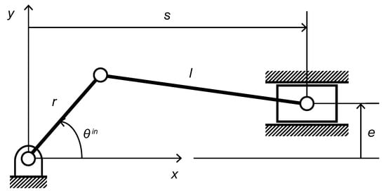
Figure 1.
Schematic of the planar four-link slider–crank mechanism.
The slider position is determined by three variables corresponding to the linkage dimensions: the crank length r, the connecting-rod length l, and the vertical offset e between the slider axis and the crank axis. For a given crank angle , the slider position s is expressed as []
Equation (1) yields two possible solutions, corresponding to the two circuits or assembly configurations illustrated in Figure 2. This indicates that a single set of linkage dimensions can define two distinct slider positions.
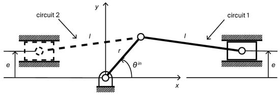
Figure 2.
Two possible configurations of the planar slider–crank mechanism.
2.2. Dimensional Synthesis Principles
A slider–crank function generator is a mechanism designed to produce a specific slider motion—either as absolute position or relative displacement—in response to variations in the crank angle. The task of determining the linkage dimensions and initial position that satisfy these prescribed motion requirements is referred to as dimensional synthesis. In most design cases, the requirements are specified as a sequence of n precision points, defined using either relative or absolute specifications.
Under the relative specification, the ith precision point is denoted as for , representing the incremental changes in crank angle and slider position relative to the initial position (Figure 3). This representation is particularly suited for applications where relative motion variations are of primary concern rather than absolute positioning.
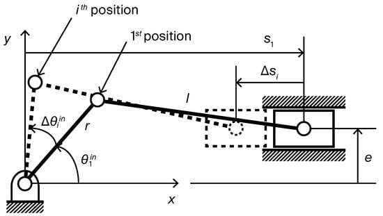
Figure 3.
Precision points defined by the relative specification.
In contrast, the absolute specification defines each ith precision point as for , specifying the absolute values directly (Figure 4). This form is appropriate for mechanisms required to achieve prescribed absolute positions at specified crank angles. Since the first point inherently determines the initial position, no additional determination is required during synthesis.
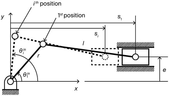
Figure 4.
Precision points defined by the absolute specification.
It is well established that up to five precision points can be synthesized exactly under the relative specification [], while up to three points can be synthesized exactly under the absolute specification. The data-driven approach proposed in this study, however, is not constrained by these limits on the number of precision points—instead, it provides approximate solutions with only minor errors.
3. Data-Driven Synthesis Methodology
3.1. Dataset Generation
3.1.1. Overview and Notation
This study considers a four-link slider–crank linkage, as illustrated in Figure 1. The crank (input link) is assumed to undergo a complete counterclockwise rotation. Of the two possible circuits shown in Figure 2, only circuit 1 (slider to the right of the ground pivot) needs to be considered, since the corresponding slider position for the other circuit can be obtained by symmetry, as explained in Section 3.1.3.
Under this configuration, each dataset sample is defined as a collection of the form for , where m is the number of training precision points, and each component is specified as follows:
- Dimension vector : A vector representing linkage dimensions, composed of the crank length r, connecting-rod length l, and offset e.
- Crank angles : A set of m input angles sampled over a full rotation , for .
- Slider positions : The corresponding slider positions computed for each , for .
Each pair constitutes a training precision point under absolute specification. To distinguish the training data from the user-defined prescribed precision points used during the synthesis stage (see Section 3.2.4 and Section 4), barred symbols (e.g., , ) are used to denote the former, and unmarked symbols (e.g., , ) are used to denote the latter.
For relative specifications, the random initialization layer described in Section 3.2.5 converts relative values into absolute ones, allowing dataset generation and training to focus entirely on absolute specifications while avoiding the need to train directly on relative cases.
3.1.2. Dimension Generation
To generate a diverse set of feasible linkage configurations, r, l, and e are uniformly sampled within the following geometric constraints:
where M denotes a predefined upper bound. This range accommodates both positive and negative offsets including in-line configurations (), thereby ensuring structural diversity.
To allow a complete crank rotation, the following geometric condition must be satisfied:
Additionally, to prevent degenerate cases where an excessively long connecting rod produces negligible slider displacement, the connecting-rod length is limited by an upper bound relative to the crank length:
Only triplets satisfying these constraints are retained as valid dimension vectors , ensuring that the resulting dataset contains only kinematically feasible slider–crank linkages.
3.1.3. Crank Angle Sampling and Slider Position Computation
Crank angles for are uniformly sampled over to fully cover the motion cycle. By extending the sampling range beyond the standard one-revolution interval and including a neighborhood around and , the dataset naturally preserves the periodic continuity between the start and end of the cycle, thereby preventing discontinuities. Counterclockwise rotation is assumed, as clockwise rotation produces mirrored behavior and is redundant for training.
Given and , the corresponding slider positions for are computed from Equation (1), which yields the slider position in either circuit 1 or circuit 2, as shown in Figure 2, depending on the sign used—“+” for circuit 1 and “−” for circuit 2. Owing to the symmetry between the two circuits, only the solution with the “+” sign, denoted as , needs to be calculated. Let be the slider position obtained using the “−” sign. The symmetry between the two circuits can then be expressed as
The relationship indicates that using only circuit 1 preserves a one-to-one correspondence between the crank angle and slider displacement and is therefore adopted for consistent dataset construction. Since circuit 2 can be analytically derived from circuit 1 (Equation (5)) and provides redundant kinematic information, its explicit inclusion is unnecessary.
3.1.4. Final Dataset Composition
Each dataset sample fully describes the motion of a specific slider–crank linkage, enabling the model to learn the mapping from to . By iterating over a wide range of valid configurations, a large-scale dataset can be generated efficiently. For example, approximately 100,000 samples can be produced in 2.3–2.4 s on a single-core CPU (41–42 k samples/s).
Constraint-violating samples are known to hinder convergence and generalization in data-driven synthesis [,], making dataset-level validity essential. To ensure this validity, all samples in this study are analytically generated under explicit geometric constraints, combined with uniform sampling and a single-circuit representation to maintain physically feasible slider–crank configurations with balanced, non-redundant coverage. This construction naturally preserves the crank’s periodic motion and establishes a one-to-one nonlinear angle–displacement relationship while keeping the dataset compact. Whereas prior kinematics-related studies often relied on large sample volumes rather than explicit validity screening [], the proposed approach constructs a uniformly sampled and fully valid large-scale dataset of 100,000 samples for training, thereby reducing distributional bias in a more systematic manner.
3.2. Modeling and Training
3.2.1. Training Pipeline
Figure 5 presents the overall training pipeline, with each component described in the subsequent sections. The model is trained on m absolute training precision points, each specified as for , to predict the dimension vector that best satisfies the training precision points while minimizing the loss function.
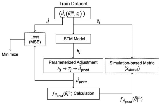
Figure 5.
Training pipeline of the data-driven synthesis framework.
The user-driven synthesis procedure, illustrated in Figure 6, follows steps similar to those in the training pipeline, with the addition of a random initialization layer (Section 3.2.5) to handle relative specifications. No loss is computed during synthesis, as the outputs are treated as final predictions. The trained model is expected to generate multiple synthesized vectors with minimal error, even for unseen prescribed precision points.
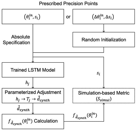
Figure 6.
User-driven synthesis procedure for prescribed precision points.
3.2.2. Parameterized Adjustment
Although the dataset contains only kinematically feasible configurations, the model may still produce invalid predictions during training, which severely undermine training stability and overall model performance [,]. Since such linkages cannot be physically assembled or complete a full crank rotation, the kinematically defined evaluation metric and the loss cannot be computed, causing the entire training pipeline to effectively collapse. To prevent these issues and ensure validity at the prediction stage, a parameterized adjustment layer is incorporated into the model, as shown in Figure 5 and Figure 6.
From the full-rotation condition in Equation (3), the following bounded constraints can be derived:
These bounded constraints are enforced by applying appropriate transformations to the raw outputs , , and :
where the functions are defined as
Although Equation (4) constrains the connecting-rod length l only during dataset generation to exclude degenerate cases, the transformation in Equation (7) maps to , a domain that lies entirely within the feasible design space. The final predicted dimensions are then expressed as
The proposed parameterization provides a compact analytical formulation that enforces physical feasibility directly into the prediction stage, enabling the model to generate only physically realizable linkages without any corrective post-processing. By enforcing the full-rotation condition in the parameterization and constructing the dataset exclusively from a single circuit, the model naturally avoids non-assemblable or circuit-switching configurations, generally yielding defect-free linkage solutions. This lightweight and architecture-agnostic transformation forms a practical bridge between kinematic constraints and data-driven modeling, and can be readily integrated into sequence-to-prediction architectures beyond the LSTM. In the context of slider–crank function generation, it offers a generalizable representation that makes machine learning-based dimensional synthesis both feasible and effective, improving training stability and model convergence.
3.2.3. Design of LSTM-Based Architecture
An LSTM-based architecture [,] is adopted for its proven capability in solving sequence-to-prediction problems, which involve processing ordered sequences containing a variable number of precision points. This flexibility allows a single model trained with m precision points to generalize to inputs containing fewer points, while in this study, is chosen to balance between expressiveness and computational efficiency. Beyond the generic LSTM framework, the proposed model integrates two mechanism-specific components, establishing a task-specific architecture tailored for the dimensional synthesis of slider–crank function generators:
- Parameterized adjustment layer derived from the geometric constraints of the slider–crank mechanism (Section 3.2.2).
- A simulation-based metric quantifying the precision-point reproducibility of the predicted linkage (Section 3.2.4).
The training objective is to minimize the mean squared error (MSE) between the predicted dimension vector and the corresponding vector in the dataset.
where denotes the ith component of .
3.2.4. Evaluation Metric
To complement MSE, a simulation-based metric is introduced to quantify the deviation between the motion produced by the predicted linkage and that specified by the training precision points:
where denotes the function that maps and to the corresponding slider position. The same metric is used in the dimensional synthesis procedure for a set of n user-defined prescribed precision points:
where is similarly defined for and . In both cases, values closer to zero indicate higher accuracy in reproducing the specified motion. This metric has the advantage of being independent of the dataset’s ; as long as the precision points are accurately reproduced, alternative valid solutions are also considered correct.
3.2.5. Random Initialization
Although the model is trained exclusively on absolute specifications, a random initialization layer, as shown in Figure 7, is introduced to enable the processing of relative specifications during user-driven synthesis.
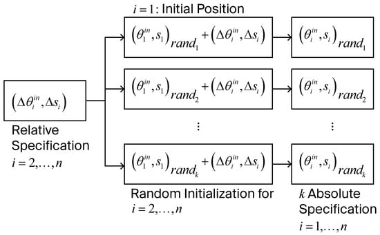
Figure 7.
Random initialization procedure converting relative specifications into absolute specifications.
For a given set of relative prescribed precision points, , where , k random initial positions are generated. The initial crank angle is sampled from , and the initial slider position from . This range reflects the physical configuration limits of the slider–crank mechanism, assuming that both the crank and connecting rod have lengths shorter than or equal to M, with the slider positioned to the right of the ground pivot. The relative precision points are then converted to absolute values as follows:
This procedure generates k absolute cases for each relative specification, which are ranked in ascending order of . By decoupling the handling of relative cases from the model, this strategy enhances generalization while keeping the dataset compact. Setting initializations per relative case used in this study provides sufficient diversity to ensure robust performance, as demonstrated in Section 4.
Notably, this random initialization strategy not only decouples the handling of relative specifications from the model but also serves as a structural contribution beyond conventional data augmentation. It enables the model, trained solely on absolute precision points, to generalize to relative specifications without any explicit prediction of the initial configuration, retraining, or modification of the model architecture. This design effectively simplifies the overall model structure while maintaining dataset compactness, achieving training-free, zero-shot generalization from absolute to relative precision-point specifications.
3.2.6. Implementation Configuration
The model employs a bidirectional Long Short-Term Memory (LSTM) network comprising seven layers, each followed by a dropout layer (rate = 0.3), and a final linear prediction head. Training is performed using the Adam optimizer (learning rate = , weight decay = ), with a scheduler that reduces the learning rate by 0.8 at epoch 200. The model is trained for 3000 epochs on an NVIDIA RTX 4090 GPU (designed by NVIDIA Corporation, Santa Clara, CA, USA) using 100,000 samples per epoch, with a total training time of approximately 1.41 h. An online training strategy is adopted, in which training samples are generated dynamically at each epoch to improve generalization. Once trained, the model can instantly predict valid linkage dimensions for any set of prescribed precision points.
4. Results
This section presents dimensional synthesis examples of slider–crank linkages for prescribed precision points, provided in two specification types: absolute and relative. The overall synthesis performance was first evaluated using the defined in Section 3.2.4, computed on an evaluation dataset of 200,000 valid slider–crank configurations, independently generated using the same procedure described in Section 3.1. The parameterized model achieved an average of 0.0009, whereas the unparameterized model recorded a significantly higher value of approximately 5.014 (over computable cases), within the sampling range in which the maximum link length was set to (Section 3.1.2). These results demonstrate that the proposed parameterization substantially improves convergence stability and motion accuracy.
In the following synthesis examples, the prescribed absolute slider position s (or prescribed relative displacement ), the synthesized linkage dimensions , and the corresponding slider position computed from are all expressed in arbitrary units, as the absolute scales of these quantities are irrelevant to the analysis. Accordingly, units are omitted from the tables for clarity.
The synthesized linkages are obtained using the model trained with the methodology described in Section 3. For each example, only the single best prediction is presented, determined using the . The errors listed in the tables represent the absolute deviation at each ith precision point, computed as
Notably, no invalid or non-evaluable configurations were observed in either the evaluation or the synthesis examples, indicating that the proposed parameterization effectively preserves kinematic feasibility in all tested cases.
4.1. Absolute Precision Point Case
Two representative cases are examined under absolute specifications: three and twenty precision points. The three-point case, shown in Figure 8 and Table 1, corresponds to the theoretical maximum number of precision points solvable through exact synthesis under absolute specifications, whereas the twenty-point case, illustrated in Figure 9 and Table 2, uses the same setting as described in Section 3.2.3. Figure 8 and Figure 9 present the synthesized linkage diagrams and displacement plots, while Table 1 and Table 2 list the prescribed precision points , the slider displacements of the resulting linkages, and the absolute errors at each precision point. In the plots, the prescribed precision points are marked with circles, arranged sequentially from left to right. As shown in the tables, the magnitudes of the errors at precision points are negligible, confirming the model’s ability to synthesize linkage dimensions that satisfy the prescribed motion with high accuracy.
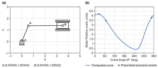
Figure 8.
Results for three absolute prescribed precision points: (a) second position, (b) displacement plot.

Table 1.
Summary of synthesized results for three absolute prescribed precision points, with example solution .
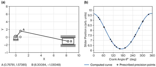
Figure 9.
Results for twenty absolute prescribed precision points: (a) fourth position, (b) displacement plot.

Table 2.
Summary of synthesized results for twenty absolute prescribed precision points, with example solution .
4.2. Relative Precision Point Case
For relative precision point specifications, the results are presented for the cases of five and twenty precision points. The five-point case, shown in Figure 10 and Table 3, corresponds to the theoretical maximum solvable through exact synthesis under relative specifications, while the twenty-point case, illustrated in Figure 11 and Table 4, adopts the same setting as in the absolute case. Similar to the absolute specification plots, the precision points are marked with circles that progress sequentially from left to right. However, the first point may not appear at the leftmost position due to the presence of an initial position. To ensure consistency, all angular values in the plots and tables exceeding are normalized to the range by subtracting where necessary.
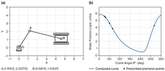
Figure 10.
Results for five relative prescribed precision points: (a) fourth position, (b) displacement plot.

Table 3.
Summary of synthesized results for five relative prescribed precision points with example solution .
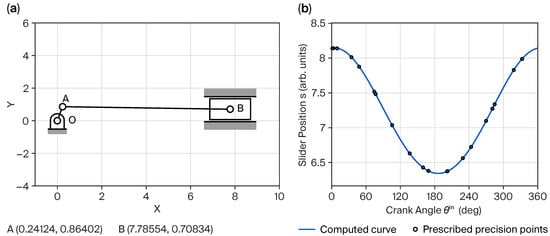
Figure 11.
Results for twenty relative prescribed precision points: (a) fifteenth position, (b) displacement plot.

Table 4.
Summary of synthesized results for twenty relative prescribed precision points, with example solution .
Since the relative prescribed precision points are converted to absolute positions using the initial position, the plots and tables list the resulting absolute positions, with the first entry in each table representing the initial position. The results show that the proposed method also generates slider–crank mechanisms that closely satisfy the desired functional relationship between the input crank rotation and output slider displacement for relatively specified precision points.
5. Conclusions
This study presents a novel data-driven approach to the dimensional synthesis of planar four-link slider–crank function generators. Departing from conventional methods, the proposed framework directly predicts linkage dimensions for all physically realizable input–output relationships and consistently yields valid, defect-free solutions through the parameterized adjustment.
Trained for only a few hours under the proposed methodology, the model can accurately synthesize linkage dimensions for any number of prescribed precision points—absolute or relative—enabling rapid computation without the need for retraining or post-processing. It also achieves high dynamic accuracy across the full motion range, supported by the comprehensive kinematic dataset, sequence-to-prediction architecture, and simulation-based evaluation metric. From the perspective of multi-solution screening, although only the single best-performing solution was presented in Section 4, the framework inherently generates multiple candidate linkages that are quantitatively evaluated and ranked using ; the random initialization process in relative specifications further enhances this capability.
The explicit parameterization specific to the slider–crank mechanism and the comprehensive kinematic-based dataset made the present study feasible, and they also indicate that extending the methodology to more complex mechanisms, such as six-link slider–cranks, would be a reasonable direction for future research. Although the underlying kinematic equations for higher-complexity mechanisms are available, making dataset generation theoretically possible, identifying an appropriate training strategy or mechanism-specific parameterization remains an important topic for future investigation. Overall, the trained model provides a foundation for advanced design tools and standalone software, with strong potential for practical deployment. By improving accessibility for non-expert designers and streamlining the synthesis process, this approach can substantially enhance both the efficiency and usability of mechanism design in engineering practice.
Author Contributions
Conceptualization, W.R.K. and J.K.S.; methodology, W.R.K. and J.K.S.; software, W.R.K.; validation, W.R.K. and J.K.S.; formal analysis, W.R.K. and J.K.S.; investigation, W.R.K. and J.K.S.; resources, W.R.K. and J.K.S.; data curation, W.R.K. and J.K.S.; writing—original draft preparation, W.R.K.; writing—review and editing, J.K.S.; visualization, W.R.K. and J.K.S.; supervision, J.K.S.; project administration, W.R.K. and J.K.S. All authors have read and agreed to the published version of the manuscript.
Funding
This research received no external funding.
Institutional Review Board Statement
Not applicable.
Informed Consent Statement
Not applicable.
Data Availability Statement
The original contributions of this study are included in the article. Further inquiries can be directed to the corresponding author.
Conflicts of Interest
The authors declare no conflicts of interest.
References
- Sandor, G.N. A General Complex-Number Method for Plane Kinematic Synthesis with Applications; Columbia University: New York, NY, USA, 1959. [Google Scholar]
- Erdman, A.; Sandor, G.; Kota, S. Mechanism Design: Analysis and Synthesis; Number V. 1 in Mechanism Design: Analysis and Synthesis; Prentice Hall: Hoboken, NJ, USA, 2001. [Google Scholar]
- Erdman, A.G. Three and four precision point kinematic synthesis of planar linkages. Mech. Mach. Theory 1981, 16, 227–245. [Google Scholar] [CrossRef]
- Almandeel, A.; Murray, A.P.; Myszka, D.H.; Stumph, H.E., III. A Function Generation Synthesis Methodology for All Defect-Free Slider-Crank Solutions for Four Precision Points. J. Mech. Robot. 2015, 7, 031020. [Google Scholar] [CrossRef]
- Huang, X.; He, G.; Liao, Q.; Wei, S.; Tan, X. Solving a planar four-bar linkages design problem. In Proceedings of the 2009 International Conference on Information and Automation, Zhuhai/Macau, China, 22–24 June 2009; pp. 1586–1590. [Google Scholar] [CrossRef]
- Wampler, C.W.; Morgan, A.P.; Sommese, A.J. Complete Solution of the Nine-Point Path Synthesis Problem for Four-Bar Linkages. J. Mech. Des. 1992, 114, 153–159. [Google Scholar] [CrossRef]
- Plecnik, M.M.; Michael McCarthy, J. Numerical Synthesis of Six-Bar Linkages for Mechanical Computation. J. Mech. Robot. 2014, 6, 031012. [Google Scholar] [CrossRef]
- Plecnik, M.M.; Michael McCarthy, J. Computational Design of Stephenson II Six-Bar Function Generators for 11 Accuracy Points. J. Mech. Robot. 2015, 8, 011017. [Google Scholar] [CrossRef]
- Plecnik, M.M.; McCarthy, J.M. Kinematic synthesis of Stephenson III six-bar function generators. Mech. Mach. Theory 2016, 97, 112–126. [Google Scholar] [CrossRef]
- Balli, S.S.; Chand, S. Defects in link mechanisms and solution rectification. Mech. Mach. Theory 2002, 37, 851–876. [Google Scholar] [CrossRef]
- Chase, T.R.; Mirth, J.A. Circuits and Branches of Single-Degree-of-Freedom Planar Linkages. J. Mech. Des. 1993, 115, 223–230. [Google Scholar] [CrossRef]
- Freudenstein, F. Approximate Synthesis of Four-Bar Linkages. Trans. Am. Soc. Mech. Eng. 1955, 77, 853–859. [Google Scholar] [CrossRef]
- Plecnik, M.M.; McCarthy, J.M. Five Position Synthesis of a Slider-Crank Function Generator. In Proceedings of the ASME 2011 International Design Engineering Technical Conferences & Computers and Information in Engineering Conference (IDETC/CIE), Washington, DC, USA, 28–31 August 2011; pp. 317–324. [Google Scholar] [CrossRef]
- McLarnan, C.W. Synthesis of Six-Link Plane Mechanisms by Numerical Analysis. J. Eng. Ind. 1963, 85, 5–10. [Google Scholar] [CrossRef]
- Akhras, R.; Angeles, J. Unconstrained nonlinear least-square optimization of planar linkages for rigid-body guidance. Mech. Mach. Theory 1990, 25, 97–118. [Google Scholar] [CrossRef]
- Suh, C.; Mecklenburg, A. Optimal design of mechanisms with the use of matrices and least squares. Mech. Mach. Theory 1973, 8, 479–495. [Google Scholar] [CrossRef]
- Shariati, M.; Norouzi, M. Optimal synthesis of function generator of four-bar linkages based on distribution of precision points. Meccanica 2011, 46, 1007–1021. [Google Scholar] [CrossRef]
- Porta, J.M.; Ros, L.; Creemers, T.; Thomas, F. Box Approximations of Planar Linkage Configuration Spaces. J. Mech. Des. 2006, 129, 397–405. [Google Scholar] [CrossRef]
- Javash, M.S.; Ettefagh, M.M.; Hamidi, Y.E. Optimum design method for four-bar function generator using AIS and genetic algorithms. In Proceedings of the 2013 IEEE INISTA, Albena, Bulgaria, 19–21 June 2013; pp. 1–6. [Google Scholar] [CrossRef]
- Rao, A. Synthesis of 4-bar function-generators using geometric programming. Mech. Mach. Theory 1979, 14, 141–149. [Google Scholar] [CrossRef]
- Cabrera, J.; Simon, A.; Prado, M. Optimal synthesis of mechanisms with genetic algorithms. Mech. Mach. Theory 2002, 37, 1165–1177. [Google Scholar] [CrossRef]
- Ortiz, A.; Cabrera, J.; Nadal, F.; Bonilla, A. Dimensional synthesis of mechanisms using Differential Evolution with auto-adaptive control parameters. Mech. Mach. Theory 2013, 64, 210–229. [Google Scholar] [CrossRef]
- Vasiliu, A.; Yannou, B. Dimensional synthesis of planar mechanisms using neural networks: Application to path generator linkages. Mech. Mach. Theory 2001, 36, 299–310. [Google Scholar] [CrossRef]
- Hoskins, J.; Kramer, G. Synthesis of mechanical linkages using artificial neural networks and optimization. In Proceedings of the IEEE International Conference on Neural Networks, San Francisco, CA, USA, 28 March–1 April 1993; p. 822-J. [Google Scholar] [CrossRef]
- Khan, N.; Ullah, I.; Al-Grafi, M. Dimensional synthesis of mechanical linkages using artificial neural networks and Fourier descriptors. Mech. Sci. 2015, 6, 29–34. [Google Scholar] [CrossRef]
- Kim, W.R.; Jung, J.; Ha, J.U.; Lee, D.; Shim, J.K. Data-Driven Dimensional Synthesis of Diverse Planar Four-bar Function Generation Mechanisms via Direct Parameterization. arXiv 2025, arXiv:2507.08269. [Google Scholar]
- Yim, N.H.; Lee, J.; Kim, J.; Kim, Y.Y. Big data approach for the simultaneous determination of the topology and end-effector location of a planar linkage mechanism. Mech. Mach. Theory 2021, 163, 104375. [Google Scholar] [CrossRef]
- Yim, N.H.; Ryu, J.; Kim, Y.Y. Big data approach for synthesizing a spatial linkage mechanism. In Proceedings of the 2023 IEEE International Conference on Robotics and Automation (ICRA), London, UK, 29 May–2 June 2023; pp. 7433–7439. [Google Scholar] [CrossRef]
- Kwak, S.W.; Shim, J.K.; Mo, Y.K. Kinematic Conceptual Design of In-Line Four-Cylinder Variable Compression Ratio Engine Mechanisms Considering Vertical Second Harmonic Acceleration. Appl. Sci. 2020, 10, 3765. [Google Scholar] [CrossRef]
- Freudenstein, F. An Analytical Approach to the Design of Four-Link Mechanisms. Trans. Am. Soc. Mech. Eng. 1954, 76, 483–489. [Google Scholar] [CrossRef]
- Yu, J.; Li, Y.; Yang, H.; Zhang, Y. Physics-Informed Machine Learning for Mechanical Performance Prediction of ECC-Strengthened Reinforced Concrete Beams: An Empirical-Guided Framework. Math. Comput. Appl. 2025, 30, 94. [Google Scholar] [CrossRef]
- Regenwetter, L.; Giannone, G.; Srivastava, A.; Gutfreund, D.; Ahmed, F. Constraining Generative Models for Engineering Design with Negative Data. arXiv 2023, arXiv:2306.15166. [Google Scholar]
- Nurizada, A.; Dhaipule, R.; Lyu, Z.; Purwar, A. A Dataset of 3M Single-DOF Planar 4-, 6-, and 8-Bar Linkage Mechanisms With Open and Closed Coupler Curves for Machine Learning-Driven Path Synthesis. J. Mech. Des. 2024, 147, 041702. [Google Scholar] [CrossRef]
- Jiang, N.; Zhang, M.; van Hoeve, W.J.; Xue, Y. Constraint Reasoning Embedded Structured Prediction. J. Mach. Learn. Res. 2022, 23, 1–40. [Google Scholar]
- Schweidtmann, A.M.; Weber, J.M.; Wende, C.; Mitsos, A. Obey validity limits of data-driven models through topological data analysis and one-class classification. Optim. Eng. 2022, 23, 855–876. [Google Scholar] [CrossRef]
- Hochreiter, S.; Schmidhuber, J. Long Short-Term Memory. Neural Comput. 1997, 9, 1735–1780. [Google Scholar] [CrossRef]
- Shiri, F.M.; Perumal, T.; Mustapha, N.; Mohamed, R. A comprehensive overview and comparative analysis on deep learning models: CNN, RNN, LSTM, GRU. arXiv 2023, arXiv:2305.17473. [Google Scholar] [CrossRef]
Disclaimer/Publisher’s Note: The statements, opinions and data contained in all publications are solely those of the individual author(s) and contributor(s) and not of MDPI and/or the editor(s). MDPI and/or the editor(s) disclaim responsibility for any injury to people or property resulting from any ideas, methods, instructions or products referred to in the content. |
© 2025 by the authors. Licensee MDPI, Basel, Switzerland. This article is an open access article distributed under the terms and conditions of the Creative Commons Attribution (CC BY) license (https://creativecommons.org/licenses/by/4.0/).