Abstract
Deep oil and gas reservoirs exist under high-temperature and high-pressure (HTHP) conditions. Conventional coring without thermal preservation during retrieval induces thermal imbalance, biasing petrophysical and phase measurements and distorting resource evaluation. Internationally, most temperature-preserved corers are designed for low-temperature conditions and rely on passive insulation, whereas existing HTHP simulators can reproduce pressure and temperature but lack the capability to evaluate active thermal retention throughout coring and retrieval. Here, we develop and validate a full-scale testing platform for active in situ temperature-preserved coring (active ITP-coring), consisting of a simulated HTHP core chamber, a through-chamber conductive module, a high-pressure simulation module, an ambient-temperature simulation module, and a data acquisition and control module. The system operates stably at 150 °C and 140 MPa, reproduces realistic ambient cooling histories (with maximum and average rates of 11.22 and 5.11 °C/min), and demonstrates that, under HTHP conditions, active preservation limits the internal temperature drop to 4.2 °C over 40.5 min (temperature retention of 98.93%), markedly outperforming the 13.1 °C decrease within 14.9 min without active preservation. These results verify the system’s reliability and, at the laboratory scale, demonstrate the feasibility of active ITP-coring, providing a reproducible methodology and quantitative evidence for engineering deployment in deep reservoirs.
1. Introduction
The exploitation of deep oil and gas resources has become increasingly routine [1,2]. Globally, deep- and ultra-deep as well as HTHP exploration and development are advancing across multiple basins, including HPHT wells and deep water plays in the US Gulf of Mexico, ultra-deep water production in Brazil’s pre-salt province, and projects in the Caspian/Kazakhstan region [3,4]. China is the world’s largest crude-oil importer, with recent imports of approximately 11 million barrels per day, primarily supplied by Russia and Saudi Arabia [5,6]. Against this backdrop, extensive exploration activities at depths exceeding 4500 m have been carried out in China. Currently, deep (4500 m) and ultra-deep (6000 m) oil and gas reservoirs are primarily located in the Tarim Basin [7,8,9,10] and are estimated to account for over 90% of the basin’s proven reserves [11]. The deepest oil and gas well in China, the Shendi Take-1 well, has reached a depth of 10,910 m [12]. However, deep oil and gas resource exploitation typically occurs under high-temperature conditions, which significantly affect basic reservoir parameters such as porosity and permeability [13,14,15,16,17,18]. Scientific drilling remains the most direct approach for acquiring in situ reservoir information at depth, but traditional coring techniques lack thermal insulation, resulting in inaccurate evaluation and inefficient development of deep oil and gas resources [19,20]. To address this issue, Academician XIE He-ping proposed the development of active ITP-coring technology, which aims to retrieve reservoir samples while maintaining their original in situ temperatures for subsequent analysis [21].
Research on thermal insulation coring technologies has been largely limited to applications in combustible ice sampling. For example, Germany’s OMEGA project developed the Multiple Autoclave Corer (MAC) and the Dynamic Autoclave Piston Corer (DAPC). After sampling, cores are stored at low temperatures on the surface using external refrigeration devices [22]. The Japan National Petroleum Corporation commissioned Aumann & Associates Inc. (AAI) to develop the Pressure Temperature Core Sampler (PTCS), which maintains temperature using insulated inner tubes and thermoelectric cooling technology [23]. The China Institute of Marine Geology developed the Pressure and Temperature Preservation System (PTPS), which uses a ZrO2-8%Y2O3 coating on the outer tube to reduce heat exchange with the environment. A vacuum insulation layer is formed between the outer tube and the pressure cylinder, and both are coated with thermal insulation materials [24]. However, these corers are limited to low-temperature preservation and mainly adopt passive thermal insulation approaches. Such methods are inadequate for maintaining in situ temperatures, especially in deep reservoirs characterized by HTHP conditions. Therefore, the development of active ITP-coring technology is essential for deep reservoirs, enabling stable and long-term maintenance of in situ high temperatures [25,26].
Active ITP-coring technology remains largely unexplored, and corresponding experimental testing equipment must be independently developed. Kabir et al. [27] developed a system capable of simulating pressures corresponding to a well depth of 9100 m, but it lacked temperature field control, limiting its utility in thermal management studies. Morandi et al. [28] built a drilling simulation setup that replicated 5000 m well conditions, with bottom-hole pressure reaching 69 MPa and drilling fluid temperatures of up to 170 °C. Li [29] developed the first drilling simulation device of China, ZM-35, capable of simulating pressure environments at a well depth of 3500 m. Cai et al. [30] created an HTHP simulation wellbore operating at 120 °C and 40 MPa. Xiao [31] developed an HTHP simulation platform for electromagnetic logging tools, validated at 120 MPa and 120 °C. However, the existing equipment is designed primarily to simulate formation temperature and pressure conditions but lacks the specific testing capabilities required for the development of active ITP-coring in deep reservoirs. As such, these systems are not suitable for evaluating the dynamic temperature control performance of active ITP-coring throughout the coring and retrieval process. It is therefore necessary to establish a dedicated HTHP test platform for active ITP-coring that integrates a through-chamber conductive module and a data acquisition and control-based feedback system, enabling closed-loop, quantitative evaluation of the temperature-preservation process under reproducible ambient-cooling histories.
Building upon previous research, the active ITP-coring process has been established, and the working principles of each functional module have been clarified [32,33]. In this study, a specialized testing system capable of simulating a coupled HTHP environment of 150 °C and 140 MPa is independently developed to support in situ active ITP-coring in deep reservoirs. The feasibility of this coring process is comprehensively validated under laboratory conditions, providing essential experimental and technical support for future temperature-preserved coring applications in deep reservoir environments.
2. Active ITP-Coring Process and Functional Requirements for the Testing System
The active ITP-coring system consists of an active heating material module, a conductive module, and a temperature sensing and control module [34]. The system is based on the wire-line coring process. After coring is completed, the power supply cable is delivered from the surface to the downhole corer using the wireline and salvage spear. Upon completion of the retrieval process, the salvage spear activates the conductive module on the central rod, establishing electrical continuity between the surface cable and the downhole active ITP-coring system. Once powered, the system begins operation, actively preserving the in situ temperature of the core.
The working principle of the active ITP-coring system is illustrated in Figure 1 [32]. The system uses active heating materials as the core heat source, powered by a surface supply through cables and conductive modules. A temperature sensing and control module continuously monitors the in situ thermal condition of the core and evaluates real-time temperature variations. Based on the feedback, the heating output is dynamically regulated to compensate for heat loss, ensuring that the core consistently maintains its in situ temperature throughout the retrieval process.
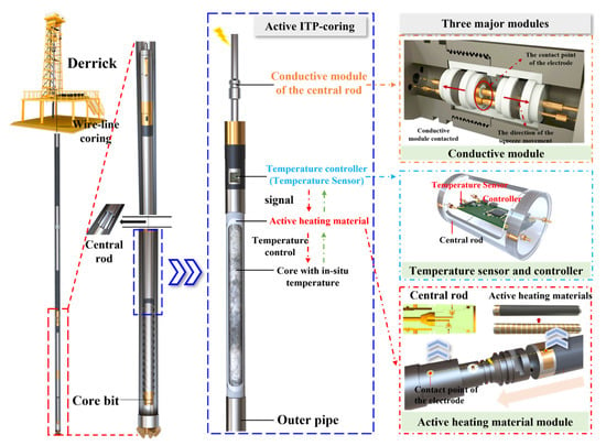
Figure 1.
Working principle of active ITP-coring system for deep reservoirs.
Building on the integration of the three core modules, and accounting for the structural and operational requirements of the corer, a modular testing system has been developed to support multi-functional evaluation of the active ITP-coring process in deep reservoirs [35,36]. This system is designed in alignment with the corer’s structure and working procedures and must fulfill the following technical requirements:
- 1.
- Simulated HTHP core chamber: Based on the structure of a real corer, the chamber serves as the main body of the testing system and is designed to simulate coupled HTHP conditions of 150 °C and 140 MPa.
- 2.
- HTHP heating and autonomous temperature control: To evaluate the active ITP-coring technology, the system is required to deliver stable power to the heating materials and enable signal transmission from temperature sensors under HTHP environment.
- 3.
- Environmental temperature simulation: To simulate the temperature variation during core retrieval, the system replicates a continuous temperature decrease of 3–7.5 °C/min, assuming a temperature gradient of 3–5 °C/100 m and a core lifting speed of 100–150 m/min.
- 4.
- Data acquisition and remote control: To ensure safe operation and effective data analysis under HTHP conditions, the system is configured to support remote control and data acquisition.
The development concept and key technical parameters of the testing system are shown in Figure 2.
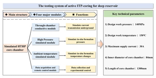
Figure 2.
Development ideas and technical parameters of testing system.
3. Overall and Modular Design of Testing System
Following the development concept outlined in Figure 2, the testing system comprises four modules: the ambient temperature simulation module, high-pressure simulation module, through-chamber conductive module, and data acquisition and remote control module, each designed around a simulated HTHP core chamber. The overall system layout is illustrated in Figure 3.
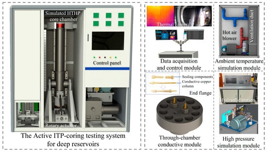
Figure 3.
Overall design of testing system.
3.1. Simulated HTHP Core Chamber
The simulated HTHP core chamber is the central component of the testing system, designed to replicate deep in situ HTHP conditions and to provide integrated testing conditions for evaluating the active ITP-coring system. Its primary design challenge is to achieve effective sealing, reliable insulation, and stable through-chamber electrical conduction under HTHP conditions.
The chamber is constructed based on the actual geometry of the coring tool and adopts a single-layer cylindrical structure, optimized to accommodate internal temperature sensors and electrical transmission components. A flanged sealing structure is employed at both ends. The internal diameter of the chamber is 84 mm, and the outer dimensions and material specifications conform to the Design Standard for “Ultra-High Pressure Vessels”. Water is used as the working medium. Considering corrosion resistance, thermal strength, and high-temperature oxidation resistance [37], the material chosen is 17-4PH (0Cr17Ni4Cu4Nb) hardened martensitic stainless steel. After heat treatment, the material exhibits a yield strength of 1180 MPa and a tensile strength of 1310 MPa [38]. Since 150 °C has a minimal effect on the mechanical properties of the material and strain hardening enhances strength under ultra-high pressure, the bursting pressure exceeds the full yield pressure. Therefore, the wall thickness is designed using the bursting failure criterion, applying the Faupel equation [39,40].
Because the test chamber operates under combined high-temperature and ultra-high-pressure conditions, all cylindrical sections simultaneously sustain elevated temperature and pressure. Accordingly, when calculating the wall thickness of the chamber, the influence of temperature must be taken into account and converted into an equivalent load that is included in the design pressure. The design criterion for bursting failure is adopted as follows:
Substitute Equation (1) into Equation (2) to obtain the formula for calculating the thickness of the cylinder:
In the above equations, Pb represents the bursting pressure; ReL and Rm are the material’s yield strength (1180 MPa) and tensile strength (1310 MPa), respectively. K denotes the ratio of the outer to inner radius, Ri is the inner radius (42 mm), φ is the material strength reduction factor at the design temperature, and δ is the calculated wall thickness. The design working temperature and maximum working pressure are 150 °C and 140 MPa. For design purposes, a working pressure of 200 MPa is adopted, and the design pressure P is set as 1.08 times this value. A bursting safety factor nb of 3.0 is applied.
Based on these values, the cylindrical wall thickness calculated from Equation (4) is 25.92 mm, which is rounded to 26 mm. In practice, additional thickness is included to account for machining tolerances, corrosion allowance, and structural vulnerabilities at the chamber ends. To facilitate disassembly and assembly, a mechanical–hydraulic rotation mechanism is incorporated. Ultimately, to ensure structural integrity and safety under high-stress conditions, the final wall thickness is determined to be 34 mm. The resulting HTHP test chamber adopts a cylindrical design with an overall length of 1490 mm, inner diameter of 84 mm, and outer diameter of 152 mm.
To comprehensively evaluate the stress state of the cylindrical shell under internal pressure with sealed ends, the three principal stress components for a thick-walled cylinder (Lame solution) are listed for any radius r ∈ [Ri, R0], and the equivalent stress is computed for strength verification. The stress components are:
where R0 is the outer radius of the cylinder (R0 = Ri + δ). For the present design, Ri = 42 mm and δ = 34 mm; hence, R0 = 76 mm. The internal pressure used in the analytic check is P = 140 MPa. Substituting these values gives the axial stress constant δz = 61.56 MPa. The von Mises equivalent stress is calculated as follows:
Evaluating the above at the inner surface (r = Ri) yields σVM,inner = 349.10 MPa; at the outer surface, (r = R0) σVM,outer = 106.62 MPa. The equivalent stress reaches its maximum at the inner wall, as is typical for thick-walled cylinders. The allowable stress used here is [σ] = ReL/1.5 = 786.67 MPa; thus, σVM,inner < [σ]. Therefore, under the design condition of internal pressure 140 MPa and temperature 150 °C, the cylinder with a wall thickness of 34 mm possesses an adequate safety margin in terms of static strength.
The temperature and pressure coupling behavior of the core chamber was simulated using ANSYS Workbench 2022R1 (Steady-State Thermal and Static Structural modules) to evaluate its mechanical integrity and deformation characteristics under HTHP conditions. A thermo-mechanical coupling analysis was performed by adopting an isotropic linear-elastic model with thermal strain included. Plastic deformation and contact nonlinearities were neglected, and the temperature was assumed to be uniformly distributed along the wall thickness. The material properties of 17-4PH stainless steel were defined in the software as listed in Table 1, sourced from the ASM Handbook [41].

Table 1.
Properties of 17-4PH.
Boundary conditions were prescribed as follows: a uniform wall temperature of 150 °C (thermal step, reference 22 °C) and an internal pressure of 140 MPa applied on the inner cylindrical surface (structural step), with the outer surface held at zero gauge pressure. The lower sidewall region was constrained using a fixed support condition (Ux = Uy = Uz = 0) to simulate the mechanical assembly constraints. End regions were treated as adiabatic in the thermal step. This fixed support corresponds to the clamping interface in practical assembly and provides a conservative estimate of local stress concentration near the support. The simulation results are shown in Figure 4. The maximum von Mises stress reached 890.15 MPa, occurring at the fixed support location, while the maximum deformation was 1.5621 mm at the opposite end of the chamber.
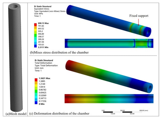
Figure 4.
Temperature–pressure coupling simulation of the core chamber with HTHP environments.
The calculated safety factor of the chamber is nb = 1.32, which satisfies the design requirements. In practical applications, plastic materials such as rubber pads are typically placed at the support interface, allowing sufficient deformation and further reducing local stress concentrations. Consequently, the actual maximum stress would be significantly lower than 890.15 MPa, yielding a higher safety margin. Therefore, the adopted model provides a conservative estimation for the structural design of the chamber under HTHP environments.
To further analyze the stress distribution, two representative circumferential sections were selected: the middle area of the fixed support surface (surface 1) and the middle section of the chamber body (surface 2). Under the coupled conditions of 140 MPa and 150 °C, the von Mises stress and total deformation fields for these sections are presented in Figure 5. Both sections display a radially symmetric stress pattern that decreases outward, consistent with the hoop-stress characteristic under uniform internal pressure. Simulation results indicate that the maximum von Mises stress at surface 1 is approximately 505.96 MPa, whereas surface 2 attains about 348.33 MPa; the corresponding maximum total deformations are 0.054 mm (surface 1) and 0.652 mm (surface 2). Thus, the constrained surface exhibits high stress but low deformation, which is attributable to restricted thermal expansion and the resulting local stress concentration, while the unconstrained surface accommodates loading primarily through larger deformation with lower peak stress. This trend agrees with the Lame analytical solution for thick-walled cylinders, where the hoop stress dominates the von Mises distribution and decays radially outward.
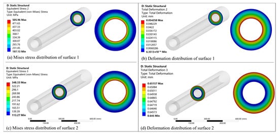
Figure 5.
Mises stress and deformation of surface 1 and surface 2 at 140 MPa and 150 °C.
Building on Figure 5, a parametric comparison of Mises stress and deformation is conducted for the two sections under temperature and pressure. The Mises stress and deformation responses of surface 1 and surface 2 were analyzed under various temperature and pressure conditions. Owing to the fixed support constraint at surface 1, the Mises stress is highly sensitive to temperature. In Figure 6a and Figure 7a, when internal pressures are set to 0 MPa, 30 MPa, and 60 MPa, deformation is dominated by thermal expansion, and both Mises stress and deformation increase approximately linearly with temperature. When the pressure increases to 90, 120, and 140 MPa, pressure-induced deformation partly offsets thermally induced deformation, resulting in a non-linear trend in which stress and deformation first decrease and then increase with temperature. For surface 1 at zero pressure, the von Mises stress increases from about 0 MPa to about 656.97 MPa as temperature rises, whereas at 140 MPa, it exhibits a minimum around 50 °C and then reaches about 505.97 MPa at 150 °C. In Figure 6b and Figure 7b, under a constant ambient temperature of 22 °C, the Mises stress and deformation at surface 1 increase nearly linearly with internal pressure. At elevated temperatures, thermal effects dominate and internal pressure counterbalances them; therefore, at high temperatures, both stress and deformation at surface 1 show an inverse relationship with pressure. These findings suggest that in the structural design of active ITP-coring testing systems, particular attention should be given to reinforcing the constrained lower wall to prevent local yielding while maintaining sufficient flexibility in the unconstrained section to accommodate thermal deformation safely.
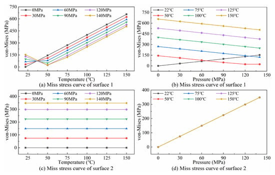
Figure 6.
Mises stress curve of surface 1 and surface 2.
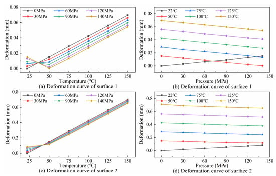
Figure 7.
Deformation curve of surface1 and surface 2.
Since no fixed support is applied at surface 2, thermally induced stress and deformation are allowed to develop and relax. As shown in Figure 6c,d, the Mises stress at surface 2 is strongly correlated with internal pressure and remains nearly unaffected by temperature. However, as seen in Figure 7c,d, temperature has a significant influence on deformation. At constant pressure, deformation increases with temperature. At constant high temperature, thermally induced deformation partially offsets pressure-induced deformation, and in the absence of support constraints, a weak negative correlation with pressure is observed. In magnitude, deformation of surface 1 remains small (below about 0.07 mm across all cases) and, at high temperature, increasing pressure from 0 to 140 MPa reduces it by only about 0.015 mm; deformation of surface 2 is much larger, about 0.65 to 0.70 mm at 150 °C. The simulation results indicate that constrained regions are more sensitive to temperature-induced stress fluctuations, whereas in unconstrained regions, stress is governed primarily by pressure.
Overall, under 150 °C and 140 MPa the controlling critical location is the lower sidewall near the fixed support; the constrained region exhibits high stress with low deformation, while the unconstrained region shows lower stress with higher deformation, consistent with Figure 5.
The end faces on both sides of the chamber are sealed using flanged connections with bolted fastening. A composite sealing structure comprising a metal snap-ring gasket, conical PEEK washer, and high-temperature-resistant O-ring is adopted for end-face sealing between the chamber and end covers. The schematic diagram of the sealing structure is illustrated in Figure 8.
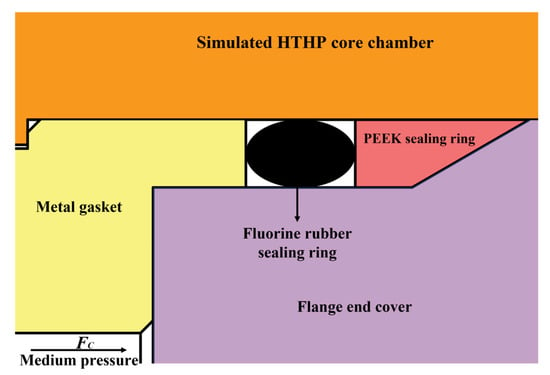
Figure 8.
End combination sealing of simulated HTHP core chamber.
According to the Waters method [42], the total axial preload F0 on the flange bolts consists of the axial force Fc generated by the high-pressure medium and the compressive force Fp required to seal the gasket components:
The sealing force Fp depends on the effective sealing width and the gasket factor, the latter being an empirical parameter derived from data recommended by Rossheim and Markl [43]. Under the rated maximum working pressure of 140 MPa, the total axial force required was calculated to be F0 = 920.11 kN. Based on structural strength and safety considerations, Grade 12.9 high-strength hex socket carbon steel bolts were selected. By evaluating their tensile and yield strength, M18 bolts were determined to be appropriate. A total of 10 bolts were evenly distributed around the flange circumference to meet both sealing and mechanical strength requirements.
To accommodate vertical testing conditions and facilitate core sample installation, a hydraulically driven rotating mechanism was integrated into the lower section of the chamber. This mechanism enables automated rotation of the chamber to any desired orientation, as illustrated in Figure 9.
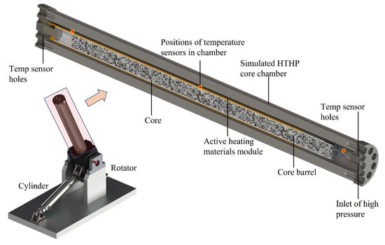
Figure 9.
Simulated HTHP core chamber.
Temperature control for both the chamber and its surrounding environment is achieved through the coordinated operation of a hot air blower and a refrigeration unit (see Section 3.4). Several high-pressure-resistant temperature sensors are strategically placed within the chamber to enable real-time monitoring of temperature distribution. Pressure conditions are generated using an external hydraulic station that supplies high-pressure fluid via hydraulic pipelines. Mechanical and electronic gauges are employed for continuous monitoring and regulation of internal pressure (see Section 3.3). A schematic of the HTHP simulation and monitoring system is presented in Figure 10.
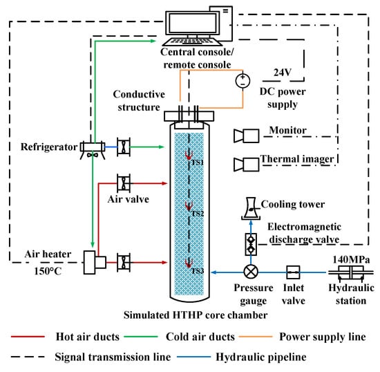
Figure 10.
Schematic diagram of the simulated HTHP core chamber.
3.2. Through-Chamber Conductive Module
The active ITP-coring system controls the inside temperature of the chamber under in situ pressure (140 MPa) by heating materials. Therefore, in addition to meeting the sealing requirements of the end under HTHP environments, the end cover of the chamber also needs to meet the real-time monitoring of the temperature inside the chamber and the power supply of heating materials through the chamber to achieve the capacity test of the active ITP-coring system under the in situ simulation environment.
In the lower part of the chamber, the flange end cap is designed with a high-pressure liquid medium injection port and two temperature sensor installation ports; in the upper part of the chamber, the flange end cap is designed with two conductive ports, a temperature sensor mounting port, and an exhaust port. The key to the design of the through holes in the flange end caps is the stability of the seal under high temperature and pressure.
The high-pressure liquid injection port and sensor installation port of the lower flange end cover are both sealed with metal conical surfaces, as shown in Figure 11a. The difficulty in designing the conductive hole of the upper flange end cover lies in both achieving sealing under HTHP environments and achieving insulation between the conductive component and the flange end cover. The special engineering plastic polyether ether ketone (PEEK) as an insulation component is adopted; this material can still maintain good electrical insulation under harsh working conditions such as high temperature, high pressure, and high humidity [44,45]. Special structures of PEEK and the conductive copper column (62 brass) are designed. PEEK adopts conical design and installs with the conductive copper column through the compression nut extrusion, with its cone deformation used to achieve the sealing. Its specific structural principle is shown in Figure 11b.
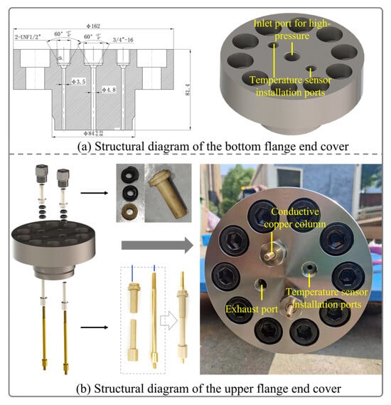
Figure 11.
Schematic diagram of through-chamber conductive module on the chamber.
3.3. High-Pressure Simulation Module
The chamber is pressurized using an external hydraulic station, with the inlet line connected to the lower end cap to simulate deep-reservoir high-pressure conditions. To ensure stable and safe pressure control, the system includes a remote-controlled pneumatic relief valve and a high-precision manual valve for dual-mode pressure regulation [46].
The high-pressure simulation module and its pressurization and relief pipelines are shown in Figure 12. The lines are designed independently to ensure safety and functional decoupling. During the pressurization phase, hydraulic fluid is injected into the core chamber through the inlet line. A check valve is mounted to prevent potential damage to the hydraulic station caused by high-temperature fluid backflow. Pressure sensors are installed to continuously monitor and record internal pressure conditions. Two pressure relief pipelines are configured: one equipped with a remote pneumatic relief valve for automated pressure release, and the other with a manual relief valve to provide redundancy in case of system failure. A heat exchange unit is additionally installed in the relief line to rapidly cool and condense the high-temperature discharge (e.g., steam), ensuring safe and efficient fluid release.
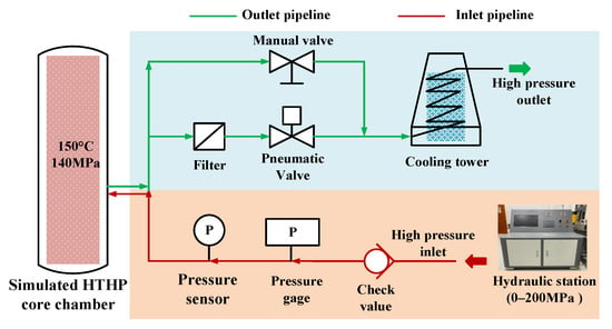
Figure 12.
Schematic diagram of high-pressure simulation module.
3.4. Ambient Temperature Simulation Module
The active ITP-coring system operates during the interval between core retrieval and its ascent to the surface. To replicate the ambient temperature fluctuations (20 °C to 150 °C) encountered during this process, an ambient temperature simulation module has been developed. This setup allows for a comprehensive evaluation of the system’s thermal retention capability under dynamic conditions. The module comprises a hot air blower, industrial air conditioner, air pipelines for heating and cooling, temperature sensors, and automated air valves. These components form a thermal simulation system with zoned temperature control across different submodules, as illustrated in Figure 13.
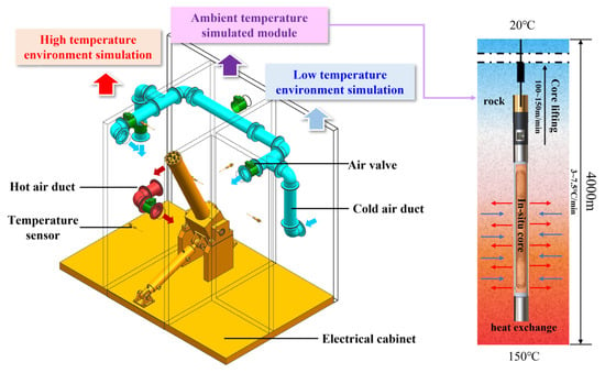
Figure 13.
Schematic diagram of ambient temperature simulation module.
In addition to cooling the core chamber, the industrial air conditioner maintains thermal stability of the electrical control system. To ensure rapid and uniform heating, multiple hot air ducts with automated dampers are installed. These dampers respond to the real-time temperature of each zone, opening and closing automatically according to preset control logic. To enhance thermal regulation efficiency, the hot air inlet is arranged at a lower position than the cold air inlet within the ambient temperature simulation module. Temperature sensors distributed at multiple locations enable automatic monitoring and closed-loop feedback control of the ambient temperature. Additionally, temperature gradients from in situ formation conditions to surface temperature can be defined and reproduced according to experimental requirements.
3.5. Data Acquisition and Remote Control Module
The data acquisition and control module includes a computer, control cabinet, temperature and pressure sensors, position sensors, cameras, thermal imagers, and data acquisition software. This module is responsible for monitoring temperature and pressure inside the simulated HTHP core chamber, acquiring test data, capturing real-time images, tracking temperature variations across multiple zones, and controlling the testing system.
As illustrated in Figure 12 and Figure 13, the system is equipped with two pressure sensors located along the high-pressure pipeline and eight temperature sensors positioned in the ambient temperature simulation module. To accurately capture the internal thermal field, three high-pressure-resistant temperature sensors are additionally installed at the upper, middle, and lower positions inside the core chamber. These sensors are of the STT-T platinum resistance type, enclosed in metal housings and filled with thermal conductive and sealing materials. They offer a temperature measurement range of −50 °C to 200 °C and maintain an accuracy of 1% F.S. under pressures up to 140 MPa.
For safety purposes, a remote control system has been developed. It connects to the host computer via a wireless network. This enables real-time communication and remote operation, allowing for accurate and timely display of equipment status and test data, as shown in Figure 14.
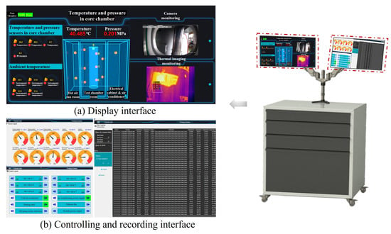
Figure 14.
Schematic diagram of data acquisition and remote control module.
4. Capability Verification of Testing System and Active ITP-Coring System
4.1. Capability Verification of Testing System
To validate the comprehensive performance of the active ITP-coring testing system under HTHP conditions, a full-scale prototype was built (Figure 15) comprising four subsystems: (i) A simulated HTHP core chamber (inner diameter 84 mm, final wall thickness 34 mm) rated for 150 °C/140 MPa; three pressure-resistant PT100 temperature sensors (STT-T series, −50–200 °C, accuracy ±1% F.S. at 140 MPa) were installed at the upper, middle, and lower axial positions. (ii) An ambient-temperature simulation unit that uses a hot-air blower, an industrial refrigeration unit, a motorized air damper, and an oil-free air compressor to deliver hot/cold air to the chamber jacket and reproduce the required heating/cooling trajectories (layout in Figure 13). (iii) A high-pressure simulation unit in which an external hydraulic station provides 0–200 MPa; the inlet/return lines include a check valve and an in-line filter; a local mechanical pressure gauge (0–200 MPa) is paired with a pressure transducer for closed-loop monitoring; and the relief manifold combines a pneumatic vent valve with a manual valve to enable remote rapid depressurization and fine pressure regulation. (iv) A data acquisition and control module that supports remote operation, real-time logging of temperature/pressure/electrical variables, safety interlocks, and automatic depressurization logic.
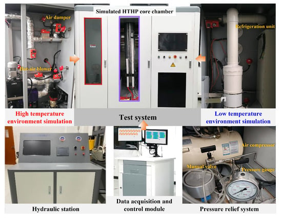
Figure 15.
Prototype of testing system for active ITP-coring.
First, a standard working condition (150 °C/140 MPa) was established to evaluate its heating efficiency, pressure control stability, sealing integrity, and through-chamber conductivity. After confirming the system’s reliability, further tests were conducted under three additional representative conditions: 50 °C/50 MPa, 100 °C/100 MPa, and 160 °C/140 MPa. Each test group followed a consistent procedure, as described below:
- Parameter setting: The target temperature and pressure were set according to each working condition, with allowable fluctuations controlled within ±5 °C and ±1 MPa, respectively.
- System preparation: The flange end caps were installed, and the exhaust port was opened. The simulated core chamber was placed vertically, filled with liquid from the bottom, and pressurized to an initial value of 5 MPa.
- Heating stage: The ambient temperature simulation module was activated to raise the environmental temperature, indirectly heating the internal medium of the simulated chamber to the target in situ temperature. Simultaneously, the active ITP heating module was activated to accelerate the warming process.
- Temperature–pressure coupling: Once the internal temperature reached the target value, hydraulic pressurization was applied to achieve the coupled HTHP state, which was then stably maintained for a designated duration.
- Pressure release and data processing: After the test, remote pressure release and manual drainage were performed. The system data were then exported for post-processing and analysis.
The experimental results are shown in Figure 16. Figure 16a shows the temperature and pressure variations under the standard condition of 150 °C/140 MPa. During the initial 140 min, the temperature gradually increased, with slight fluctuations due to manual adjustments. The environmental temperature exhibited two distinct stages: a rapid increase in the early phase due to a small temperature gradient and low heat dissipation, followed by a slower rise as the heat loss increased with a larger temperature gradient. The temperature increase inside the chamber was primarily driven by both the internal active ITP heating module and thermal conduction from the ambient environment, showing an overall linear growth trend. Due to the sealed structure of the chamber, pressure increased concurrently with temperature. To assess the sealing performance and pressure control response, two remote pressure relief operations were executed during the heating phase. After both temperature and pressure reached the set points, the system successfully maintained stability for one hour without leakage or temperature drop, validating the sealing reliability, HTHP simulation capability, and operational stability of the through-chamber conductive structure. The active insulation and heating materials also remained intact under HTHP conditions.
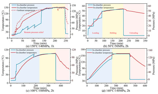
Figure 16.
Validation of testing system capability.
To test system adaptability, additional experiments were carried out under three representative conditions: 50 °C/50 MPa, 100 °C/100 MPa, and 160 °C/140 MPa, as shown in Figure 16b–d. In the 50 °C/50 MPa test (Figure 16b), the pressure was increased step-by-step and held at each level. After the chamber temperature reached the set point, pressure compensation was applied, and the system remained stable for two hours before depressurization. In the 100 °C/100 MPa test (Figure 16c), the initial pressurization slightly overshot. Pressure then gradually increased alongside temperature. Before the target temperature was reached, the pressure approached a critical level, triggering automatic pressure relief. In the 160 °C/140 MPa test (Figure 16d), no external pressurization was applied initially. The pressure increased naturally as the temperature rose, and pressure compensation was automatically triggered at the target temperature.
All three tests achieved stable two-hour operation with accurate temperature and pressure control. The active ITP heating module and through-chamber conductive components showed high reliability under different conditions. Repeated experiments under multiple HTHP scenarios confirmed the durability of the heating module and the system’s overall stability and adaptability in complex thermal-pressure environments.
4.2. Capability Verification of Active ITP-Coring System
Figure 17 illustrates the cooling process of the simulated ambient module during the experiment described in Section 4.1. This system was specifically designed to replicate the rapid temperature drop encountered during the core retrieval phase in deep coring operations, thereby providing an indoor validation platform for the active ITP system and supporting design optimization under controlled experimental conditions.
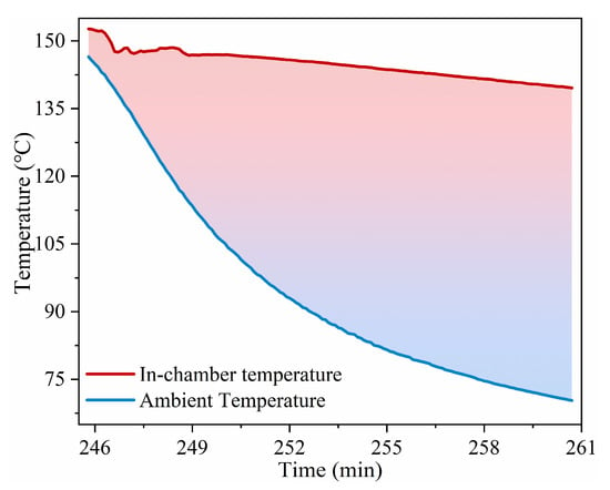
Figure 17.
Cooling curves of ambient temperature and temperature in core chamber.
During the cooling phase, cold air was continuously supplied to the simulated ambient module by the air conditioner, while residual hot air was expelled through the air valve. Meanwhile, the internal active heating module was turned off to enable rapid cooling of the chamber. As the ambient temperature decreased, the temperature difference with the external environment narrowed, leading to reduced heat exchange efficiency. This resulted in a two-stage cooling profile, with a rapid initial drop followed by a slower decline.
The maximum and average cooling rates of the simulated ambient temperature reached 11.22 °C/min and 5.11 °C/min, respectively, satisfying the required cooling rate range of 3–7.5 °C/min for coring retrieval speeds of 100–150 m/min, with a minimum simulated duration of 16.7 min. This confirms the capability of the ambient module to effectively simulate transient thermal conditions during core retrieval.
However, due to the large chamber volume and influence of room temperature, the average cooling rate only marginally meets the experimental requirements. Notably, the temperature drop inside the core chamber exhibits an approximately linear trend, in contrast to the exponential decay typically expected under passive cooling scenarios [26]. This deviation is attributed to the actively regulated cooling process, where the simulated ambient module dynamically adjusts heat transfer intensity based on the changing temperature gradient.
Within 14.9 min, the internal chamber temperature dropped by 13.1 °C, clearly indicating that without active thermal preservation, the system is unable to maintain the required in situ temperature. These results underscore the critical importance of incorporating active insulation strategies during deep coring operations.
To evaluate the comprehensive performance of the active ITP-coring system under HTHP conditions, a testing setup was established, as shown in Figure 18. The system consisted of a heating materials module and a core barrel, both enclosed within the simulated HTHP core chamber. The heating module was connected to the conductive central rod and the temperature sensing and control module via the through-chamber conductive structure located on the upper end cap of the chamber, ensuring reliable electrical connection between the internal heating unit and the external control system. The heating materials module was powered by a DC regulated power supply (24 V), while the control module was powered by a high-temperature battery. The entire setup was placed inside the ambient temperature simulation chamber, which was used to reproduce the temperature drop that occurs during core lifting from deep reservoirs. During the test, the temperatures of both the chamber and the external environment were first raised to 150 °C, followed by pressurization of the chamber to 140 MPa. Subsequently, the ambient temperature simulation unit initiated a cooling process to replicate the thermal disturbance during coring, thereby verifying the thermal preservation performance of the active ITP-coring system under simulated in situ coring conditions. The experimental results are shown in Figure 19. During the initial 16 min of cooling, the simulated ambient temperature for coring exhibited a maximum cooling rate of 15.53 °C/min and an average cooling rate of 5.02 °C/min. As cooling progressed, the rate gradually declined. Throughout this process, the active ITP-coring system remained operational to maintain the initial in situ temperature within the core chamber. At the early stage of ambient cooling, the chamber temperature showed a slight decline followed by a rebound. This behavior is attributed to the sensing and control module, which detected the drop in internal temperature and activated the heating materials module to compensate, ensuring thermal stability. As the ambient temperature continued to decrease, the temperature gradient between the chamber and its surroundings increased, leading to a gradual decline in chamber temperature. The overall cooling curve, as presented in Figure 19, exhibits a convex profile, in contrast to the linear decline observed in Figure 17, highlighting the thermal inertia effect introduced by the active ITP-coring system. Ultimately, the ambient temperature dropped to 57.6 °C, and the internal chamber temperature decreased to 148.4 °C over 40.5 min, corresponding to a temperature loss of 4.2 °C (2.76%). In comparison, under identical conditions without active ITP-coring, the temperature decreased by 13.1 °C within 14.9 min.
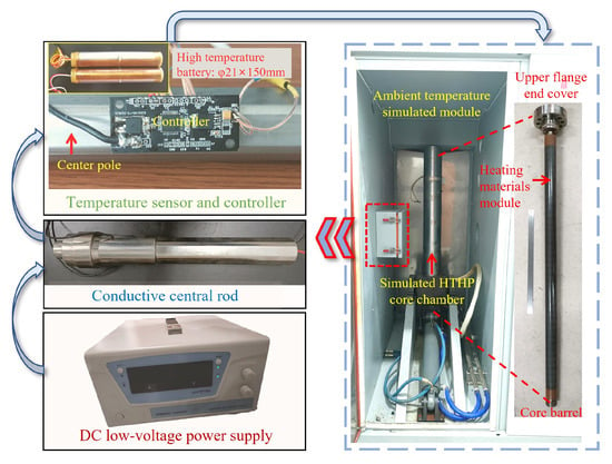
Figure 18.
Testing method of active ITP-coring system under HTHP environments.
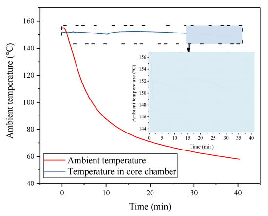
Figure 19.
Test results of active ITP-coring system under HTHP environments.
Although the simulated test conditions differ from actual downhole coring environments, the comparative test results fully demonstrate the critical role of the active ITP-coring system in maintaining in situ temperature during deep core retrieval. These results also validate the integrated capabilities of the testing system in environmental simulation, temperature control, and data acquisition under HTHP conditions. In comparison with conventional passive insulation technologies reported in the literature, the developed system offers clear advantages in terms of active thermal regulation, integrated control functionality, and evaluation precision. These strengths make it particularly suitable for assessing the dynamic performance of active ITP-coring in realistic conditions. However, limitations such as the relatively large chamber volume and partial deviations in heat transfer boundaries from actual downhole conditions remain. These issues can be addressed in future work by optimizing the structural design and refining test parameters to further improve experimental fidelity and applicability.
5. Conclusions
An active ITP-coring testing system for deep oil and gas reservoirs was developed, with detailed engineering design implemented for the core structure and four major functional modules. The following conclusions were drawn based on the experimental validation:
- The system is capable of simulating a coupled HTHP environment of 150 °C and 140 MPa, representing in situ deep reservoir conditions.
- The system can replicate ambient temperature transitions from in situ formation temperatures to ambient surface temperature during the coring process, achieving a maximum cooling rate of 11.22 °C/min and an average rate of 5.11 °C/min.
- The system integrates automated safety control and real-time monitoring functions, enabling secure pressure operation, remote regulation, and real-time transmission of operational data and system status.
- The feasibility and insulation performance of the active ITP-coring system were validated under HTHP conditions (150 °C/140 MPa). During a 40.5 min ambient cooling process, the temperature in the core chamber decreased by only 4.2 °C, achieving an in situ temperature retention of 98.93%. This performance significantly outperforms the 13.1 °C temperature drop observed in 14.9 min without active insulation, demonstrating the crucial role of the active ITP-coring system in preserving in situ thermal conditions during core retrieval.
In future studies, the active ITP-coring system will be further optimized to enhance its integration with real coring tools and operational procedures in the field. Key research directions include (i) improving the miniaturization and modularity of the control unit to adapt to downhole spatial constraints, (ii) enhancing the thermal compensation accuracy through advanced control algorithms such as adaptive PID or model predictive control (MPC), and (iii) conducting long-duration high-cycling HTHP reliability tests for key components including graphene-based heating films and insulation modules. In addition, the system will be extended to support combined testing of active and passive insulation materials, providing a more comprehensive platform for developing high-performance thermal protection strategies tailored for deep, ultra-deep, and unconventional reservoirs.
Author Contributions
Conceptualization, H.B. and Z.H.; data curation, Z.W. and Y.L.; methodology, H.B. and Z.H.; supervision, Z.H.; writing—original draft preparation, H.B.; writing—review and editing, Z.H. and Z.W. All authors have read and agreed to the published version of the manuscript.
Funding
This research was funded by the China Postdoctoral Science Foundation (Grant No. 2025T180116), the National Natural Science Foundation of China (Grant No. 52304033), the Coal-Major Project (Grant No. 2025ZD1700902), and the National Key Research and Development Program of China (Grant No. 2023YFB2390200).
Institutional Review Board Statement
No applicable.
Informed Consent Statement
No applicable.
Data Availability Statement
The data presented in this study are available upon request from the corresponding author.
Conflicts of Interest
The authors declare no conflicts of interest.
References
- Xie, H.; Gao, M.; Zhang, R.; Zhou, H.; Gao, F.; Chen, L.; Peng, X.; Li, X.; Ju, Y. Application prospects of deep in-situ condition-preserved coring and testing systems. Adv. Geo-Energy Res. 2024, 14, 12–24. [Google Scholar] [CrossRef]
- Xie, H.; Hu, Y.; Gao, M.; Chen, L.; Zhang, R.; Liu, T.; Gao, F.; Zhou, H.; Peng, X.; Li, X.; et al. Research progress and application of deep in-situ condition preserved coring and testing. Int. J. Min. Sci. Technol. 2023, 33, 1319–1337. [Google Scholar] [CrossRef]
- IEA. World Energy Investment 2025; International Energy Agency (IEA): Paris, France, 2025. [Google Scholar]
- Dou, L.; Wen, Z.; Wang, J.; Wang, Z.; He, Z.; Liu, X.; Zhang, N. Analysis of the world oil and gas exploration situation in 2021. Pet. Explor. Dev. 2022, 49, 1195–1209. [Google Scholar] [CrossRef]
- Wang, X.; Lu, Y.; Chen, C.; Yi, X.; Cui, H. Total-factor energy efficiency of ten major global energy-consuming countries. J. Environ. Sci. 2024, 137, 41–52. [Google Scholar] [CrossRef] [PubMed]
- Wang, G.; Fang, Z.; Xia, X. Analysis of the New Trend of Global Crude Oil Trade. In Annual Report on China’s Petroleum, Gas and New Energy Industry (2022–2023); China International United Petroleum & Chemicals Co., Ltd., Chinese Academy of Social Sciences, Peking University, Eds.; Springer Nature Singapore: Singapore, 2024; pp. 125–136. [Google Scholar]
- Liu, G.; Xie, Y.; Li, C. Design and mechanical optimization of multidirectional pressure-preserved coring system for deep-earth resource exploration. Int. J. Min. Sci. Technol. 2025, 35, 719–735. [Google Scholar] [CrossRef]
- Yang, X.; Tian, J.; Wang, Q.; Li, Y.; Yang, H.; Li, Y.; Tang, Y.; Yuan, W.; Huang, S. Geological understanding and favorable exploration fields of ultra-deep formations in Tarim Basin. China Pet. Explor. 2021, 26, 17. [Google Scholar] [CrossRef]
- Mao, L.; Wei, C.; Jia, H.; Lu, K. Prediction model of drilling wellbore temperature considering bit heat generation and variation of mud thermophysical parameters. Energy 2023, 284, 129341. [Google Scholar] [CrossRef]
- Wang, M.; He, L.; Zhou, Y.; Zhang, J.; Tian, Q.; Hu, R. Practices and understandings on safe drilling technologies for 9000-m-level super deep and ultra high temperature and pressure strata, Sichuan-Chongqing area. Nat. Gas Explor. Dev. 2023, 46, 44–50. [Google Scholar] [CrossRef]
- Liu, K.; Yang, P.; Yang, H.; Liu, J.; Song, Y.; Wei, X. Deep petroleum accumulation models revisited: Case studies from the Tarim basin. Acta Geol. Sin. 2023, 97, 2820–2841. [Google Scholar] [CrossRef]
- Sun, J.; Wang, J. Drilling fluid technology for deep subsurface Tako-1 well. Drill. Fluid Complet. Fluid 2025, 42, 155–166. [Google Scholar] [CrossRef]
- Saif, T.; Lin, Q.; Gao, Y.; Al-Khulaifi, Y.; Marone, F.; Hollis, D.; Blunt, M.J.; Bijeljic, B. 4D in situ synchrotron X-ray tomographic microscopy and laser-based heating study of oil shale pyrolysis. Appl. Energy 2019, 235, 1468–1475. [Google Scholar] [CrossRef]
- Mahanta, B.; Ranjith, P.G.; Vishal, V.; Singh, T.N. Temperature-induced deformational responses and microstructural alteration of sandstone. J. Pet. Sci. Eng. 2020, 192, 107239. [Google Scholar] [CrossRef]
- Kong, L.; Xie, H.; Li, C. Coupled microplane and micromechanics model for describing the damage and plasticity evolution of quasi-brittle material. Int. J. Plast. 2023, 162, 103549. [Google Scholar] [CrossRef]
- Hu, J.; Xie, H.; Li, C.; Liu, G. Evolution mechanism of permeability of hot dry rock under coupled effect of thermal fatigue and seawater interaction during coastal geothermal development. Renew. Sustain. Energy Rev. 2024, 189, 114061. [Google Scholar] [CrossRef]
- Ye, P.; Li, B.; Ren, C.; Song, H.; Fu, J.; Wu, X. Investigation on damage-permeability model of dual-porosity coal under thermal-mechanical coupling effect. Gas Sci. Eng. 2024, 123, 205229. [Google Scholar] [CrossRef]
- Yin, S.; Yang, X.; Chen, W.; Wang, L.; Chen, X. Permeability characteristics of sandstone-type uranium deposits under different temperature and confining pressure. J. Cent. South Univ. 2023, 30, 2302–2312. [Google Scholar] [CrossRef]
- Kahraman, U.; Dincer, I. Development and assessment of an integrated underground gasification system for cleaner outputs. Energy 2023, 285, 128676. [Google Scholar] [CrossRef]
- Li, C.; Xie, H.; Gao, M.; Chen, L.; Zhao, L.; Li, C.; Wu, N.; He, Z.; Li, J. Novel designs of pressure controllers to enhance the upper pressure limit for gas-hydrate-bearing sediment sampling. Energy 2021, 227, 120405. [Google Scholar] [CrossRef]
- Xie, H.; Gao, M.; Zhang, R.; Chen, L.; Liu, T.; Li, C.; Li, C.; He, Z. Study on concept and progress of in situ fidelity coring of deep rocks. Chin. J. Rock Mech. Eng. 2020, 39, 865–876. [Google Scholar] [CrossRef]
- Abegg, F.; Hohnberg, H.J.; Pape, T.; Bohrmann, G.; Freitag, J. Development and application of pressure-core-sampling systems for the investigation of gas- and gas-hydrate-bearing sediments. Deep. Sea Res. Part I Oceanogr. Res. Pap. 2008, 55, 1590–1599. [Google Scholar] [CrossRef]
- Zhu, H.; Liu, Q.; Deng, J.; Wang, G.; Xiao, X.; Jiang, Z.; Zhang, D. Pressure and temperature preservation techniques for gas-hydrate-bearing sediments sampling. Energy 2011, 36, 4542–4551. [Google Scholar] [CrossRef]
- Zhu, H.; Liu, Q.; Wong, G.; Xiao, X.; Zhu, X.; Jiang, Z.; Zhang, D. A Pressure and Temperature Preservation System for Gas-hydrate-bearing Sediments Sampler. Pet. Sci. Technol. 2013, 31, 652–662. [Google Scholar] [CrossRef]
- Shi, X.; Li, C.; Li, J.; He, Z.; Yu, B.; Xie, Y.; Xie, H. Self-sealing control principle and technology of in-situ temperature pressure preserved coring for deep oil and gas. Pet. Sci. 2025, in press. [Google Scholar] [CrossRef]
- He, Z.; Yang, Y.; Yu, B.; Yang, J.; Jiang, X.; Tian, B.; Wang, M.; Li, X.; Sun, S.; Sun, H. Research on properties of hollow glass microspheres/epoxy resin composites applied in deep rock in-situ temperature-preserved coring. Pet. Sci. 2022, 19, 720–730. [Google Scholar] [CrossRef]
- Kabir, C.S.; Hasan, A.R.; Jordan, D.L.; Wang, X. A Wellbore/Reservoir Simulator for Testing Gas Wells in High-Temperature Reservoirs. SPE Form. Eval. 1996, 11, 128–134. [Google Scholar] [CrossRef]
- Morandi, A.C.; Karunakaran, D.; Dixon, A.T.; Baerheim, M. Comparison of Full-Scale Measurements and Time-Domain Irregular Sea Analysis for a Large Deepwater Jack-Up. In Proceedings of the Offshore Technology Conference, Houston, TX, USA, 4–7 May 1998. [Google Scholar]
- Li, S. Construction of China’s first drilling simulation experimental device. Oil Drill. Prod. Technol. 1990, 3, 91. [Google Scholar] [CrossRef]
- Cai, L.; He, D.; Guo, J. Design of simulation wellbore withstand high temperature and high pressure. Machinery 2008, 35, 19–22. [Google Scholar]
- Xiao, S. Research on the Drilling Tool Structure and Its Supporting Simulate Device of EM-MWD Applied to the Deep Hole. Master’s Thesis, China University of Geosciences, Wuhan, China, 2013. [Google Scholar]
- Yu, B.; He, Z.; Yang, J.; Wei, Z.; Li, C.; Xie, H. Innovative Design of a Conductive Center Pole for an Active Thermal Insulation and Coring System in Deep Rock. Appl. Sci. 2023, 13, 1242. [Google Scholar] [CrossRef]
- Yu, B.; Zhao, W.; Chen, L.; Gao, M.; He, Z.; Hao, W. Innovative design of active insulation system for in-situ fidelity coring in deep strata. Chin. J. Eng. Des. 2020, 27, 407–415. [Google Scholar] [CrossRef]
- He, Z.; Xie, H.; Gao, M.; Chen, L.; Yu, B.; Hu, Y.; Yang, J. Design and Verification of a Deep Rock Corer with Retaining the In Situ Temperature. Adv. Civ. Eng. 2020, 2020, 8894286. [Google Scholar] [CrossRef]
- Zhang, C.; Wang, E.; Wang, Y.; Zhou, X. Development and application of multi-functional test system for coal and gas outburst simulation. Chin. J. Rock Mech. Eng. 2022, 41, 995–1007. [Google Scholar] [CrossRef]
- Li, Z.; Huang, W.; Chen, J.; Cen, J.; Cao, W.; Li, F.; Jiang, F. An enhanced super-long gravity heat pipe geothermal system: Conceptual design and numerical study. Energy 2023, 267, 126524. [Google Scholar] [CrossRef]
- Zheng, J.; Sang, Z. Process Equipment Design, 5th ed.; Chemical Industry Press: Beijing, China, 2020. [Google Scholar]
- Sun, Y.; Hebert, R.J.; Aindow, M. Effect of heat treatments on microstructural evolution of additively manufactured and wrought 17-4PH stainless steel. Mater. Des. 2018, 156, 429–440. [Google Scholar] [CrossRef]
- Namgung, I.; Giang, N.H. Investigation of Burst Pressures in PWR Primary Pressure Boundary Components. Nucl. Eng. Technol. 2016, 48, 236–245. [Google Scholar] [CrossRef]
- Li, T. Research on Key Technologies for Design of Ultra High Pressure Vessels Based on Failure Modes. Ph.D. Thesis, Zhejiang University, Hangzhou, China, 2017. [Google Scholar]
- Committee, A.H. Properties and Selection: Irons, Steels, and High-Performance Alloys; ASM International: Almere, The Netherlands, 1990. [Google Scholar]
- Yi, F.; Zhou, M. Research on the Calculation Method of Pre tightening Force of Pressure Vessel Flange Bolts. J. New Ind. 2020, 10, 59–60+64. [Google Scholar] [CrossRef]
- Xie, Y.; Ai, B.; Ren, X.; Zhou, Q.; Bi, L. Analysis and Suggestions on the Design Method of Waters Flange. Petro-Chem. Equip. Technol. 2015, 36, 6–10+15. [Google Scholar] [CrossRef]
- Wang, B.; Yu, S.; Mao, J.; Wang, Y.; Li, M.; Li, X. Effect of basalt fiber on tribological and mechanical properties of polyether-ether-ketone (PEEK) composites. Compos. Struct. 2021, 266, 113847. [Google Scholar] [CrossRef]
- Mo, X.; Zhang, Y.; Li, Y.; Huang, P.; Fu, S. Thermal and Mechanical Properties of Polyetheretherketone/Polyetherimide Alloy. Polym. Mater. Sci. Eng. 2023, 39, 1–9. [Google Scholar] [CrossRef]
- Lin, X.; Liu, Y.; Song, H.; Liu, Y. System design for 700 °C power plants: Integration scheme and performance evaluation. Energy 2023, 267, 126453. [Google Scholar] [CrossRef]
Disclaimer/Publisher’s Note: The statements, opinions and data contained in all publications are solely those of the individual author(s) and contributor(s) and not of MDPI and/or the editor(s). MDPI and/or the editor(s) disclaim responsibility for any injury to people or property resulting from any ideas, methods, instructions or products referred to in the content. |
© 2025 by the authors. Licensee MDPI, Basel, Switzerland. This article is an open access article distributed under the terms and conditions of the Creative Commons Attribution (CC BY) license (https://creativecommons.org/licenses/by/4.0/).