Abstract
The global shift towards cleaner energy sources is driving the adoption of hydrogen as an environmentally friendly alternative to fossil fuels. Among the forms currently available, Liquid Hydrogen (LH2) offers high energy density and efficient storage, making it suitable for large-scale transport by rail. However, the flammability of hydrogen poses serious safety concerns, especially when transported through confined spaces such as railway tunnels. In case of an accidental LH2 release from a freight train, the rapid accumulation and potential ignition of hydrogen could cause catastrophic consequences, especially if freight and passenger trains are present simultaneously in the same tunnel tube. In this study, a three-dimensional computational fluid dynamics model was developed to simulate the dispersion and explosion of LH2 following an accidental leak from a freight train’s cryo-container in a single-tube double-track railway tunnel, when a passenger train queues behind it on the same track. The overpressure results were analyzed using probit functions to estimate the fatality probabilities for the passenger train’s occupants. The analysis suggests that a significant number of fatalities could be expected among the passengers. However, shorter users’ evacuation times from the passenger train’s wagons and/or longer distances between the two types of trains might reduce the number of potential fatalities. The findings, by providing additional insight into the risks associated with LH2 transport in railway tunnels, indicate the need for risk mitigation measures and/or traffic management strategies.
1. Introduction
Pollution and energy shortages are critical global challenges today, driven by the increasing demand for energy due to population growth and industrial expansion. The over-reliance on fossil fuels significantly contributes to environmental degradation, leading to air pollution and climate change. In this context, the European Green Deal [1], launched by the European Commission in 2019, represents an ambitious plan to achieve climate neutrality within the European Union by 2050. This objective requires eliminating net greenhouse gas emissions through an energy transition encompassing all sectors of the economy, including industrial production, transportation, as well as the residential and agricultural sectors [2]. The reduction in emissions by at least 55% by 2030, compared to 1990 levels, constitutes a crucial intermediate milestone towards obtaining climate neutrality by mid-century. To this end, regulatory and financial instruments have been introduced to promote sustainable practices as well as the implementation of innovative technologies. In this context, the adoption of alternative energy carriers to fossil fuels becomes essential, ensuring both emission reductions and energy efficiency [3].
Among the various options currently available, hydrogen stands out as one of the most promising due to its versatility and potential applications across multiple sectors, including electricity generation, heating, heavy industry, and transportation. Specifically, hydrogen produced from renewable sources, known as green hydrogen, represents a strategic alternative for the decarbonization of sectors that are particularly challenging to electrify, thereby making a significant contribution to the overall reduction in the carbon footprint [4,5]. However, for hydrogen to play a leading role in energy transition, it is essential to develop an adequate logistical infrastructure enabling its transportation from production sites to end-use locations [6].
Currently, the main transportation methods include dedicated pipelines, road transport via tank trucks, and rail transport. Rail transport is becoming very interesting where dedicated pipelines are not economically viable due to logistical constraints, high costs, and long implementation timeframes. It is also favored due to its ability to move large volumes of hydrogen per trip while simultaneously reducing emissions associated with road transport [7]. Rail transport is more eco-friendly than road transport, with 1 freight train replacing up to 52 heavy goods vehicles and reducing CO2 emissions by 80–100% [8,9]. Hydrogen can be transported in various forms, including compressed gas in container trailers and Liquid Hydrogen (LH2) in thermo-insulated cryogenic vessel trailers [10]. Among these options, the transportation of LH2 emerges as the most efficient solution in terms of energy density, as it allows for the storage of a greater quantity of substance per unit volume compared to its gaseous form. One of the primary challenges associated with the railway transportation of hydrogen is its high flammability, along with the risk of explosions in the event of an accidental release, especially in confined environments such as tunnels [11], where dangerous substances can become trapped making them extremely hard to remove [12]. This aspect becomes particularly critical on railway routes where the simultaneous transport of hazardous materials and passengers is expected. In a hypothetical scenario involving the accidental leakage of LH2 from a train’s cryo-container blocked inside a tunnel, the evaporated liquid hydrogen might rapidly accumulate under the ceiling, forming a highly explosive mixture. If, at that moment, a passenger train moves on the same railway track and is forced to queue, the resulting explosion might have catastrophic consequences for the occupants of the passenger train. The most recent Italian standard regarding the safety of railway tunnels requires that a risk analysis be conducted to investigate various scenarios related to the transport of dangerous goods, including the release of hydrogen from freight trains [13]. This standard is aligned with the criteria and principles established by the European Union Agency for Railways [14] regarding the risk management framework for the inland transport of dangerous goods.
In this context, a summary of the literature review on the safety of railway tunnels in the event of accidental fires and/or explosions is presented in Table 1. It is worth noting that many studies have investigated railway tunnel safety in relation to small- or medium-sized fires originating from passenger train wagons, while only a few papers have focused on the effects of hydrogen leakage from hydrogen-powered trains or those transporting this substance, highlighting the challenges related to explosion risks and overpressure propagation in confined tunnel environments.
Nevertheless, a significant knowledge gap remains concerning the accidental release of LH2 from a freight train blocked inside a tunnel and its impact on the occupants of a passenger train queued on the same railway track. Given the lack of papers that have addressed the potential negative effects of LH2 release from a freight train on the safety of the occupants of a passenger train queued in the same tunnel tube, this research may contribute to increasing our knowledge by quantifying the corresponding risk level.
Therefore, the present study aims to fill the aforementioned gap through a three-dimensional CFD modeling of an accidental LH2 release from a train’s cryo-container and its potential explosion in a railway tunnel. This modeling was developed using ANSYS Fluent version 2023 R1 [30], and its results, in terms of overpressures generated by the explosion, were combined with probit functions to evaluate the consequences of such an accidental event on the safety of the occupants of a passenger train approaching on the same track.
The structure of the paper is as follows: Section 2 outlines the material and methods used, while the proposed CFD modeling is introduced in Section 3, with its results presented and discussed in Section 4. Finally, Section 5 offers conclusions, practical implications, and potential directions for future research.
2. Materials and Methods
2.1. Railway Tunnel Investigated
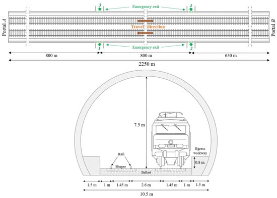
This study investigated the design of a single-tube double-track railway tunnel located in a mountainous area along an Italian high-speed/high-capacity rail line. It is 2250 m long, straight, and features a horseshoe-shaped cross-section with an area of 70 m2, a width of 10.5 m, and a height of 7.5 m (see Figure 1). The railway tunnel is characterized by an average upward longitudinal slope of 4.5‰ from Portal A to Portal B and is equipped with the minimum safety requirements established by European regulations [31]. It includes emergency exits every 800 m, for a total of two per side: the first pair (1 and 3) is located at 800 m and the second pair (2 and 4) at 1600 m from Portal A. The railway tunnel under consideration is subjected to natural ventilation only.
2.2. Operating Model of the Rail Line
The operating model of the rail line along which the above-mentioned tunnel is located involves the simultaneous transit of both passenger and freight trains, including those carrying LH2.
The reference passenger train consists of 12 wagons, each measuring 26 m in length, and two locomotive units—one positioned at the front and the other at the rear—each 20 m long. It has a total length of 358.5 m, with its components spaced 0.5 m apart. Both wagons and locomotive units have a width of 3 m and a height of 4 m.
The reference freight train transporting LH2 has a total length of 649 m. It includes a front locomotive unit, with the same dimensions as those mentioned above, and 37 cryo-containers, each 16 m long and 2.6 m in diameter. All the cryo-containers and the locomotive unit are spaced 1 m apart [8,32].
2.3. Accident Scenario
The simulated accident scenario involves the LH2 release from the rear of the last cryo-container of the freight train, through a 50 mm diameter hole—typical value considered in quantitative risk assessments for accidental continuous release from tank containers [33,34]—located at approximately 1 m above the ballast surface (see Figure 2). The freight train is assumed to travel downhill towards Portal A, when it stops due to certain circumstances and starts to release LH2. This leakage is considered to occur at the midpoint of the tunnel length (1125 m from Portal A) as this location has been shown to maximize the size of the resulting flammable hydrogen cloud [35], which is expected to move towards Portal B due to the chimney effect induced by the longitudinal slope. Simultaneously, a passenger train is considered to enter the tunnel through Portal B using the same rail track, and to queue 400 m upstream of the LH2 leakage position, corresponding to the average length of a passenger train. The LH2 release is assumed to begin at time t = 0, when the passenger train stops.
Figure 2.
Schematization of the accident scenario in the double-track railway tunnel tube under investigation, with a view of the LH2 leakage from the last cryo-container of the freight train blocked in the tunnel, and the passenger train stopped behind it, as well as the escape direction of the passenger train occupants towards the emergency exit (specified with the number 2) and/or Portal B.
2.4. LH2 Release Rate
The cryo-container from which the LH2 is released has a diameter of 2.6 m and a length of 16 m. Consequently, it can contain up to 5000 kg of LH2 [36,37] at −253 °C, considering a filling degree of 80–85%. Given the size of the hole and the pressure at which LH2 is stored (10 bar), Equation (1) [38] provides a release rate () of 13.3 kg/s for a total duration of about 375 s:
where ρ is the density of LH2 (70.8 kg/m3), A is the area of the hole (1.96 × 10⁻³ m2), CD is the flow discharge coefficient (0.6 [39]), p is the cryo-container pressure (1,000,000 Pa), p0 is the atmospheric pressure (101,325 Pa), g is the gravitational acceleration (9.81 m/s2), and h is the height of liquid surface above the hole (2 m).
2.5. Material Characteristics
The type and characteristics of the material considered for the tunnel lining and railway superstructure are reported in Table 2.
2.6. Evacuation Process of Passenger Train Occupants
Figure 2 also illustrates the evacuation process of the passenger train occupants along the egress walkway towards Portal B or emergency exit 2. Specifically, since each wagon can accommodate 52 passengers and assuming a 70% occupancy rate [42], the estimated number of users per wagon is 36. Including the two train operators in the locomotive unit, the total number of people at risk is 434.
In accordance with the Italian regulations [13], the detection time—the time required for the accidental release to be identified either by an automatic device or by train staff—was assumed to be 2 min, while the total time necessary for the users to empty the wagons of the queued passenger train was assumed to be 3 min. Therefore, the total pre-movement time (tpre) is 5 min. In other words, the occupants of the passenger train begin walking towards the emergency exit 2 or Portal B along the egress walkway 5 min after the LH2 release. Regarding their movement speed during evacuation, the same regulation recommends a value of 0.3 m/s to account for the presence of elderly individuals and/or people with reduced mobility. Specifically, all the people occupying the tunnel portion going from the stopping position of the passenger train and 100 m downstream of the emergency exit 2 are considered to self-evacuate through the emergency exit 2. The remaining users are assumed to leave the tunnel via Portal B. Therefore, the passengers in the first 6 wagons at the front of the train, along with the 2 train operators (218 people in total), will self-evacuate through the emergency exit 2, while the passengers in the 6 remaining wagons (216 people in total) will leave the tunnel via Portal B.
2.7. Methodological Framework
This study falls within the field of railway tunnel safety, focusing on the transport of hazardous materials—such as LH2—by freight trains. Given the lack of studies that have addressed this topic, particularly the impact of LH2 release on the safety of the occupants of a passenger train queued in the same tunnel tube, this paper may contribute to the current state-of-the-art by quantifying the corresponding risks, while also indicating the need for mitigation measures and/or traffic management strategies.
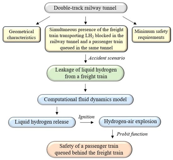
For this purpose, a 3D CFD modeling is developed to simulate the accidental release and subsequent explosion of LH2 inside a single-tube double-track railway tunnel, and probit functions are used to estimate the fatality probability for the occupants of the passenger train.
The methodological steps followed to achieve these objectives are schematically illustrated in Figure 3.
3. Numerical Modeling
3.1. CFD Code
Among the CFD tools currently available on the market, the ANSYS Fluent version 2023 R1 [30] was used. Compared to other CFD codes such as the Fire Dynamics Simulator (FDS) [43,44], which is particularly suited to reproducing fire scenarios, ANSYS Fluent offers advanced modeling capabilities for multiphase flows, making it ideal for simulating LH2 release and explosion scenarios [28,45,46,47,48].
This code includes turbulence models, heat transfer, and chemical reaction modeling, ensuring an accurate representation of any gas–liquid interactions [49], while solving the conservation equations for mass, momentum, and energy.
3.2. Liquid Hydrogen Release
3.2.1. Simulation Setup
The mixture model was used as a multiphase model to simulate the release, dispersion, and evaporation of LH2 within the tunnel [48,50,51,52]. In this model, the two-phase flow consisting of the liquid phase—LH2—and the gas phase—hydrogen–air mixture—is solved by the three-dimensional transient conservation equations for mass, momentum, and energy [35]. The mixture model regulates the phase change between the liquid and gaseous phases using the Lee evaporation-condensation model. In the latter model, the mass transfer process is governed by the vapor transport equation as a function of the difference between the ambient temperature and the hydrogen saturation temperature (i.e., 20.3 K) [53]. All the gases within the computational domain were considered incompressible, since at all time steps during the release stage the local flow velocity remained below Mach 0.3, ensuring that compressibility effects could be neglected.
For turbulence closure, the k-ε sub model was adopted, as it is considered suitable for gas dispersion in the presence of obstacles and for a wide range of turbulent flows [30], including LH2 leaks [51,52]. Table 3 shows the solution methods implemented for LH2 release scenarios.
The solution was considered converged when the residual fell below 10−3, assuming a time step of 10−3 s, which is recommended for release scenarios [35,45,50].
3.2.2. Model Developed
The developed computational domain includes the entire railway tunnel investigated. Within this domain, a freight train is modeled as being blocked inside the tunnel, and the LH2 release from the rear of its last cryo-container is simulated. Simultaneously, a passenger train is also modeled as queued on the same rail track, 400 m upstream of the LH2 release site, which is located at the midpoint of the tunnel. It is to be recorded that: (i) the LH2 release from the hole caused by the cryo-container breakage of the freight train was assumed to start at time t = 0, when the passenger train stops; (ii) the detection time was considered to be 2 min; (iii) the time necessary for emptying the wagons of the queued passenger train was assumed to be 3 min. Due to the long time interval between the moment the passenger train stops (t = 0) and the instant when all the passengers have left the train’s wagons (t = 5 min), the airflow induced from Portal B to Portal A by the piston effect of the passenger train was assumed to be negligible. Consequently, since the airflow along the structure was attributed solely to the chimney effect caused by the positive longitudinal slope, it moves from Portal A to Portal B in the same direction as the evacuation. This effect of the positive longitudinal slope was simulated in ANSYS Fluent by modifying the direction of the gravitational acceleration according to the slope angle, finding an average airflow velocity within the tunnel of approximately 1 m/s towards Portal B.
In the simulations, the “pressure outlet” boundary conditions were assigned at Portals A and B, while the “mass flow inlet” boundary condition was imposed at the surface of the LH2 release orifice. No-slip boundary conditions were applied to both the railway superstructure and the tunnel lining.
Figure 4 illustrates the model of the railway tunnel developed in ANSYS Fluent, with the details of the freight train transporting LH2 and the passenger train queued behind it.
Figure 4.
Computational domain modeled in ANSYS Fluent with the details of the freight train transporting LH2 and the passenger train queued behind it.
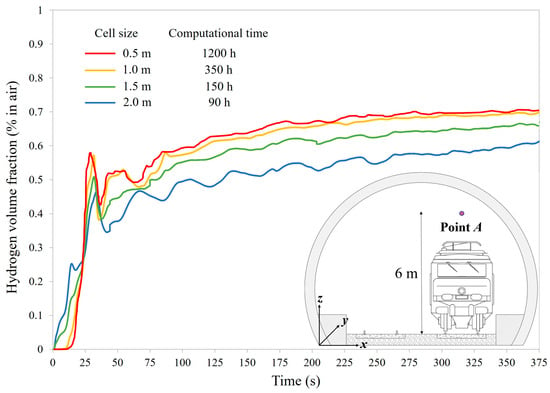
To accurately reproduce the LH2 release and evaporation process, the above-mentioned computational domain near the spill point was discretized using a very fine grid composed of tetrahedral cells with a side length of 0.025 m, corresponding to half the diameter of the LH2 leakage orifice [54]. Further away from the release site, a progressively coarser mesh resolution was adopted to contain the calculation time, with the maximum cell size determined through a grid sensitivity analysis. Figure 5 illustrates the time evolution of the hydrogen volume fraction at Point A, up to 375 s—the time when the entire LH2 content in the cryo-container was released—for tetrahedral cell dimensions of 0.5, 1, 1.5, and 2 m. Point A is located along the rail track axis used by the freight train carrying LH2 (x = 7.55 m), 10 m upstream of the spill site (y = 10 m), and at a height of 6 m above the ballast surface (z = 6.5 m).
Figure 5.
Time evolution of the hydrogen volume fraction measured at Point A as a function of the tetrahedral cell size.
Figure 5 shows that using a tetrahedral cell size smaller than 1 m does not significantly improve result accuracy, while it considerably increases the calculation time. In particular, at every time step, the discrepancy between the results obtained with the 0.5 m mesh and those with the 1 m mesh was always below 5%, confirming that a 1 m resolution is sufficiently accurate for the purposes of this study.
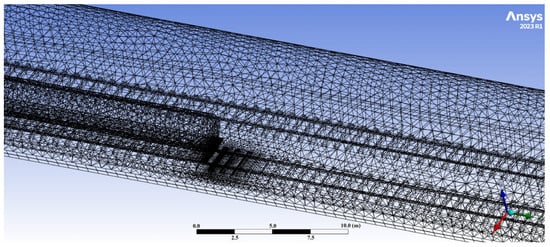
Therefore, the computational domain was discretized into a total of 1,237,779 tetrahedral cells having a side length of 1 m, with a progressively refined mesh down to 0.025 m near the release point (see Figure 6). The transition zone, where the mesh gradually and automatically changes from a coarse to fine resolution, extended approximately 3 m outward from the spill site.
3.2.3. Model Validation
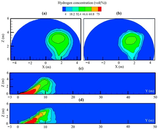
Given the lack of experimental tests involving LH2 releases in full-scale tunnels, the developed model with the optimized mesh was validated by comparing its results with those from a literature study [45], which investigated an LH2 release from a hydrogen vehicle storage tank inside a 53 m long naturally ventilated tunnel. The computational domain was modeled using the same grid size as that used for the railway tunnel investigated in our study (i.e., 1 m per side, with local refinement near the release point equal to half the diameter of the LH2 leakage orifice). Figure 7 compares the hydrogen concentration contours for different cross-sections 3 s after the leakage, demonstrating a better agreement between our model and the reference study, thereby confirming the effectiveness of the proposed model in simulating LH2 releases in tunnels.
Figure 7.
Comparison of the hydrogen concentration contours at: (a) y = 10 m cross-section obtained by Tang et al. [45]; (b) y = 10 m cross-section simulated by the develop model in our study; (c) x = 1.5 m cross-section obtained by Tang et al. [45]; (d) x = 1.5 m cross-section simulated by the develop model in our study.
3.3. Hydrogen–Air Explosion
3.3.1. Model Setup
The compressible Navier–Stokes equations, incorporating the physical sub-models relating combustion, turbulence, and thermal radiation, were numerically solved for the ideal gas mixture to simulate the explosion scenario. The combustion of hydrogen–air mixtures during explosion was modeled in ANSYS Fluent using the species transport equation, which accounts for convection, diffusion, and chemical reactions for each species in the mixture. Table 4 reports the model setup for the hydrogen–air explosion scenario simulated.
The simulation of the explosion scenario in ANSYS Fluent also requires specifying the spatial distribution of the hydrogen cloud at the moment of ignition, along with the ignition energy and location. It is to be stressed that only the mass of hydrogen within the stoichiometric concentration (i.e., 29.5% in air) was considered to participate in the explosion [60].
3.3.2. ANSYS Fluent Validation Against Hydrogen–Air Explosions
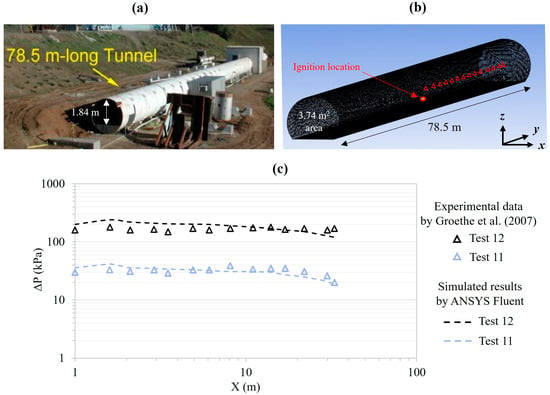
The ANSYS Fluent code was validated against the hydrogen–air explosion by replicating the experimental tests conducted by Groethe et al. [61] in a reduced-scale tunnel. Deflagration tests involved the ignition of a hydrogen–air mixture at floor level in the middle of the tunnel length: a 20% mixture (0.67 kg) without vehicle model obstacles, denoted as Test 11, and a 30% mixture (1 kg) with obstacles, referred to as Test 12 (see Figure 8). The tunnel domain was discretized into 73,377 tetrahedral cells having a side length of 0.3 m. Figure 8 also presents the comparison between the experimentally measured maximum overpressures (ΔP) and those provided by ANSYS Fluent at 1 m height along the tunnel centerline downstream of the ignition source. The simulation results had a good agreement with the experimental data, thus laying the groundwork for the development of the 3D CFD model to simulate the hydrogen–air explosion following the LH2 release in the full-scale railway tunnel investigated.
Figure 8.
CFD code validation against a hydrogen–air explosion scenario: (a) tunnel facility of the experimental test by Groethe et al. [61]; (b) schematization of the tunnel in ANSYS Fluent; (c) comparison between the experimentally measured maximum overpressures and the simulated ones along the tunnel centerline downstream of the ignition source.
It should be emphasized that, for the validation of the ANSYS Fluent code used in this study, we compared the simulation results with those obtained from a reduced-scale hydrogen explosion experiment in a tunnel. The use of a small-scale test was necessary due to the absence of full-scale experimental data in the literature for hydrogen releases in tunnels, as well as the technical, economic, and safety challenges associated with conducting full-scale experiments.
3.3.3. Schematization of the Computational Domain
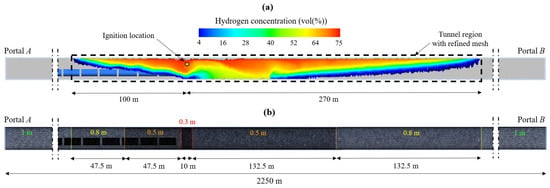
To simulate the explosion process, an additional mesh sensitivity analysis was conducted to determine the appropriate cell size that represented a suitable compromise between result accuracy and computational time. It was first necessary to define the tunnel region around the ignition point where the effects of the explosion are most pronounced, and within which the mesh would be progressively. It should be noted that the ignition site was considered near the release point—approximately 10 m upstream of the spill location (or 1135 m from Portal A)—where there is the most turbulence, and at a height that promotes hydrogen accumulation and potential ignition due to the electrical components (i.e., 6 m above the ballast surface) [28,62]. Once the ignition point and source—consisting of an electric spark of 0.1 J [63]—were defined, the criterion used to determine the domain region to be refined around the ignition site was based on the extent of the flammable hydrogen cloud at the moment of ignition. This is due to the presence of hydrogen in the mixture and the size of the cloud, which amplify the explosion’s intensity and, consequently, the propagation speed of the pressure waves [47]. In this respect, since current literature does not provide a specific reference for the exact time of ignition following a release, the most critical condition for the train passengers was considered. Within this framework, the ignition was assumed to occur 300 s after the accidental LH2 release, corresponding to the pre-movement time of the passengers.
Based on the release simulations, after 300 s, the flammable hydrogen cloud extended for about 370 m, namely 100 and 270 m from the ignition point towards Portals A and B, respectively (Figure 9a). Therefore, the effects of the explosion are expected to be most marked along this 370 m-long tunnel portion, which was discretized using a progressively coarser mesh from the ignition site towards both tunnel portals (Figure 9b). Accordingly, the tunnel domain was subdivided into a total of 2,688,787 tetrahedral cells.
4. Results and Discussion
4.1. Liquid Hydrogen Release
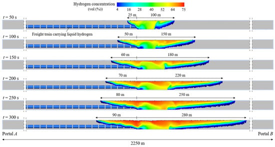
Figure 10 shows the spatial and temporal evolution of the flammable hydrogen cloud—with concentrations between 4% and 75% by volume in air—following the accidental LH2 release inside the investigated railway tunnel, up to the assumed ignition time (i.e., t = 300 s after the leakage). It can be observed that the highest concentrations are located beneath the tunnel lining due to the low density of hydrogen, which tends to rise once released. Furthermore, the propagation of the cloud is not symmetrical upstream and downstream of the leakage site due to the longitudinal slope, which generates a slight chimney effect towards Portal B. After 50, 100, 150, 200, 250, and 300 s since the release, the flammable hydrogen cloud reaches distances from the spill point of 100, 150, 180, 220, 250, and 280 m or 25, 50, 60, 70, 80, and 90 m towards Portal B or Portal A.
4.2. Hydrogen–Air Explosion
4.2.1. Pressure Wave Propagation in the Tunnel
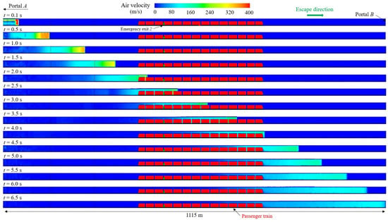
The ignition of the hydrogen cloud at stoichiometric concentration in air was assumed to occur 6 m above the ballast surface and 10 m from the rear of the cryo-container releasing LH2. Figure 11 illustrates the spatial and temporal evolution of the resulting pressure wave upstream of the ignition site, from t = 0.1 s to t = 6.5 s when the wave front reaches Portal B. Initially, a strong overpressure wave develops near the ignition point, as indicated by high airflow velocities (up to 400 m/s). Over time, the shock front propagates in the direction of the passenger train and Portal B, while the velocity field gradually decreases in intensity due to energy dissipation and wave expansion. The visualizations also indicate the interaction of the airflow with the stationary passenger train inside the tunnel, with the shock wave reaching: (i) the locomotive unit at the front of the train after 2 s from the moment of ignition; (ii) the emergency exit 2 approximately after 2.3 s; (iii) the rear of the passenger train after 4 s.
Figure 11.
Evolution of the pressure wave in space and time towards Portal B of the railway tunnel investigated.
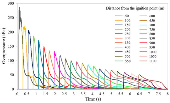
Figure 12, on the other hand, shows the overpressures over time resulting from the ignition of the H2-air mixture at various longitudinal positions at human breathing height (i.e., approximately 1.8 m above the egress walkway) along the tunnel region upstream of the freight train, starting from 50 m up to 1100 m from the ignition point. It can be observed that the shock wave propagates along the tunnel, reaching progressively greater distances as time advances. It is worth noting that the peak overpressure achieves: (i) approximately 137 kPa at the front of the passenger train—400 m from the release point, 2 s after ignition; (ii) about 84 kPa at the rear of the passenger train (i.e., around 750 m from the release point and at t = 4.2 s); (iii) about 55 kPa near Portal B—1110 m from the release point, approximately 6.5 s after ignition.
4.2.2. Peak Overpressures Along the Escape Route
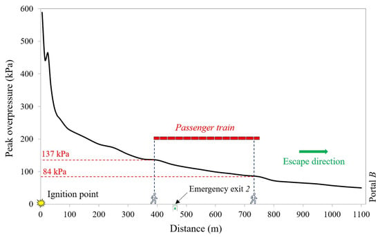
Figure 13 provides a clearer illustration of the peak overpressures upstream of the ignition point along the passenger evacuation route. Specifically, the overpressure reaches its maximum value of about 580 kPa at the ignition point and gradually decreases towards Portal B due to energy dissipation. Figure 13 also shows the position of the passenger train queued behind the freight train, along with the locations of: (i) the last user to evacuate—the passenger train operator positioned near the front of the train; (ii) the user located in the last wagon adjacent to the locomotive unit at the rear of the passenger train.
Notably, the overpressure trend experiences a slight variation near the front of the passenger train, which is attributed to the change in the blockage ratio, as the presence of the train significantly reduces the cross-sectional area that is free from obstacles. In contrast, beyond the end of the passenger train, the overpressure wave has more space to dissipate, resulting in a more rapid decrease in pressure levels. Regarding the passengers’ exposure, the individuals near the front of the passenger train are subjected to a peak overpressure of approximately 137 kPa, while the users located near the rear of the passenger train are affected by a peak overpressure of about 84 kPa. All the passengers located between the front and rear of the train are exposed to overpressures contained in the range 84–137 kPa.
4.3. Evaluation of Consequences on Passenger Train Occupants
The lack of accident data involving trains, and therefore the absence of an event tree for carrying out a risk analysis of LH2 release, currently pushes researchers to rely on other methods recognized in the literature, such as a probabilistic approach based on the probit functions. There are many published probit functions for estimating fatality levels from exposure to harmful agents; each of them presents strengths and weaknesses. However, among the models available in the literature, the UK Health and Safety Executive (HSE) probit model [64] was used for being both related to hydrogen transported through tunnels and provides the most conservative results for low peak overpressure, as in our case [65]. These are mathematical relationships that link the severity of a specific harmful event to the probability of death or injury in an individual. Based on the overpressures simulated along the evacuation route caused by the ignition of the flammable hydrogen cloud, the probability of death for each occupant of the passenger train was estimated using the aforementioned probit function model, the analytical equation of which is
where Y represents the probit function and P is the peak overpressure in bar.
The probit function () is then related to the probability of fatality () as follows:
where stands for the Gaussian error function.
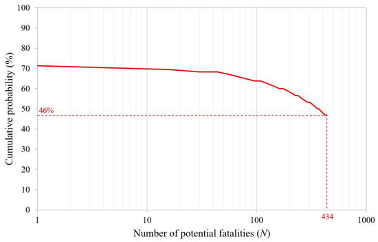
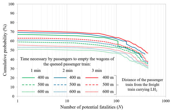
In this model, the damage level is represented by the peak overpressure experienced by an individual, which can cause a fatal pulmonary hemorrhage. According to this model, the two people near the front of the passenger train (i.e., the two train operators) have a 71% probability of death, whereas the cumulative probability of fatality for all the passengers (i.e., 434 occupants of the train) is 46%. Figure 14 illustrates the cumulative probability of experiencing N or more fatalities inside the investigated railway tunnel following the ignition of the hydrogen–air mixture.
4.4. Impact of the Pre-Movement Time and/or Distance Between the Freight and Passenger Trains
To assess the impact of passenger pre-movement time and/or the distance between the freight and passenger trains, the study was extended in two directions. First, two shorter times for the occupants to leave the wagons of the queued passenger train were considered—1 and 2 min instead of the previously assumed 3 min. These were added to the 2 min detection time, resulting in total pre-movement times of 3 and 4 min, compared to the 5 min assumed in the baseline scenario. Such a reduction could be achieved, for example, through an onboard alarm system that promptly alerts the passengers to evacuate as soon as the train stops behind the freight train releasing LH2. Second, two increased safety distances between the freight and passenger trains were also analyzed—500 and 600 m, compared to the original 400 m. Figure 15 shows that the probability of having a given number of potential fatalities N reduces by decreasing the tpre and/or increasing the safety distance between the two trains. For instance, when the distance between the two trains is 400 m, the probability of having 100 potential fatalities decreases from about 65% to 60% as tpre is reduced from 5 min to 3 min. Similarly, assuming a pre-movement time of 5 min, the probability of having the same number of potential fatalities decreases from approximately 65% to 50% when the distance between the two trains increases from 400 m to 600 m. However, it should be emphasized that a railway traffic management model aimed at ensuring a higher level of user safety should prevent the simultaneous presence of freight and passenger trains within the same tunnel tube. For instance, freight trains could be scheduled to transit only at night, when the number of passenger trains traveling is reduced.
5. Conclusions
This study aims to further the understanding of the risks associated with hazardous material releases in railway tunnels. A three-dimensional CFD model of an accidental LH2 release from a train’s cryo-container and its potential explosion was developed using ANSYS Fluent. An existing single-tube double-track railway tunnel located in a mountainous area along an Italian high-speed/high-capacity rail line—equipped with the minimum safety requirements provided by the current regulations—in which the simultaneous transit of both passenger and freight trains is allowed, including those carrying LH2, was investigated.
The simulated accident scenario involved the LH2 release from the rear of a freight train’s cryo-container, while a passenger train approached on the same track and stopped at a certain distance upstream of the leakage site.
The release simulations showed that the highest hydrogen concentrations accumulate near the tunnel ceiling, while the flammable hydrogen cloud spreads unevenly in both directions due to the tunnel’s slight longitudinal slope, which generates a chimney effect. Following ignition, the explosion simulations indicated a strong overpressure wave near the release source, gradually decreasing in intensity towards the portal due to energy dissipation.
The probability of death for each occupant of the passenger train was estimated using a probit function based on the simulated peak overpressures along the egress walkway. By considering the known positions of the passengers along the evacuation routes at the moment of ignition, cumulative fatality probabilities were calculated for different pre-movement times and safety distances between the freight and passenger trains. The results indicated that, although the explosion resulting from the LH2 release might have very severe effects on the occupants, shorter evacuation times of the users from the wagons and/or increased safety distances between trains could significantly reduce the probability of having a given number of potential fatalities.
The findings, by providing additional insights into the risks associated with LH2 transport in railway tunnels, highlight the need to implement safety mitigation measures and/or propose railway traffic management strategies. It is advisable to adopt a traffic management model that prevents the simultaneous presence of a freight train carrying hazardous materials and a passenger train within the same tunnel tube.
Future research should address structural response and possible secondary debris generation in railway tunnels due to the potential explosion of the hydrogen cloud, as well as the incorporation of uncertainty analyses in passenger walking speeds and mobility in order to more accurately represent human behavior during evacuation and improve the reliability of safety assessments in railway tunnels. Additional tunnel-specific contexts, including different geometries, longitudinal slopes, and LH2 release scenarios, might also be explored. Finally, beyond the natural ventilation assumption adopted here, the role of mechanical ventilation, which significantly affects the hydrogen cloud dispersion and may improve the evacuation conditions of passengers in the railway tunnels, should also be investigated.
Author Contributions
Conceptualization, C.C., I.R. and G.G.; methodology, C.C., I.R. and G.G.; software, C.C., I.R. and G.G.; validation, C.C., I.R. and G.G.; formal analysis, C.C., I.R. and G.G.; investigation, C.C., I.R. and G.G.; data curation, C.C., I.R. and G.G.; writing—original draft preparation, C.C., I.R. and G.G.; writing—review and editing, C.C., I.R. and G.G.; visualization, C.C., I.R. and G.G.; supervision, C.C. All authors have read and agreed to the published version of the manuscript.
Funding
This research received no external funding.
Institutional Review Board Statement
Not applicable.
Informed Consent Statement
Not applicable.
Data Availability Statement
The data presented in this study are available on request from the corresponding author. The data are not publicly available due to privacy restrictions.
Conflicts of Interest
The authors declare no conflicts of interest.
Abbreviations
The following abbreviations are used in this manuscript:
| CFD | Computational Fluid Dynamics |
| ERF | Error Function |
| FDS | Fire Dynamics Simulator |
| HRR | Heat Release Rate |
| HSE | Health and Safety Executive |
| LES | Large Eddy Simulation |
| LH2 | Liquid Hydrogen |
| PISO | Pressure-Implicit with Splitting of Operators |
| QUICK | Quadratic Upstream Interpolation for Convective Kinematics |
| SIMPLEC | Semi-Implicit Method for Pressure-Linked Equations Consistent |
| tpre | Pre-movement time |
| WALE | Wall-Adapting Local Eddy-viscosity |
References
- European Commission. The European Green Deal. 2019. Available online: https://eur-lex.europa.eu/legal-content/EN/TXT/?uri=celex:52019DC0640 (accessed on 15 July 2025).
- Akimoto, K. Assessment of road transportation measures for global net-zero emissions considering comprehensive energy systems. IATSS Res. 2023, 47, 196–203. [Google Scholar] [CrossRef]
- Sun, Y.; Anwar, M.; Hassan, N.M.S.; Spiryagin, M.; Cole, C. A review of hydrogen technologies and engineering solutions for railway vehicle design and operations. Rail. Eng. Sci. 2021, 29, 212–232. [Google Scholar] [CrossRef]
- Razi, F.; Dincer, I. Challenges, opportunities and future directions in hydrogen sector development in Canada. Int. J. Hydrog. Energy 2022, 48, 9083–9102. [Google Scholar] [CrossRef]
- Wang, T.; Wang, J.; Wang, P.; Ren, Z.; Peng, C. Electrolysis visualization and performance evaluation platform for commercial-sized alkaline water electrolyze. In Proceedings of the 10th Hydrogen Technology Convention, Foshan, China, 22–26 May 2023; pp. 390–400. [Google Scholar]
- Bondarenko, I.; Campisi, T.; Tesoriere, G.; Neduzha, L. Using detailing concept to assess railway functional safety. Sustainability 2023, 15, 18. [Google Scholar] [CrossRef]
- Ding, D.; Wu, X.Y. Hydrogen fuel cell electric trains: Technologies, current status, and future. Appl. Energy Combust. Sci. 2024, 17, 100255. [Google Scholar] [CrossRef]
- DB Cargo. Strong Logistics for Our Future: DB Cargo Tackles the Climate Neutral Transport of Green Hydrogen. 2025. Available online: https://www.dbcargo.com/rail-de-en/hydrogen (accessed on 15 July 2025).
- Zelenko, Y.; Zelenko, D.; Neduzha, L. Contemporary principles for solving the problem in noise reduction from railway rolling stock. IOP Conf. Ser Mater. Sci. Eng. 2020, 985, 012015. [Google Scholar] [CrossRef]
- International Energy Agency. Global Hydrogen Review. 2022. Available online: https://www.iea.org/reports/global-hydrogen-review-2022 (accessed on 15 July 2025).
- Han, H.; Ma, Q.; Qin, Z.; Li, Y.; Kong, Y. Experimental study on combustion and explosion characteristics of hydrogen-air premixed gas in rectangular channels with large aspect ratio. Int. J. Hydrog. Energy 2024, 57, 1041–1050. [Google Scholar] [CrossRef]
- Li, Z.; Zhang, Y.; Qiao, M.; Gao, Y.; Huang, Y. Experimental and theoretical study of the smoke back-layering length in a tunnel with cross-passage: Effects of longitudinal fire source locations. Rail. Eng. Sci. 2025. [Google Scholar] [CrossRef]
- Italian Ministry of Infrastructure and Transport. Approval of the Guidelines on Railway Safety. Official Gazette of the Italian Republic, General Series, No. 75. 31 March 2025. Available online: https://www.gazzettaufficiale.it/eli/id/2025/03/31/25A01922/SG (accessed on 15 July 2025).
- European Union Agency for Railway. Risk Management Framework for Inland Transport of Dangerous Goods: Guide for Risk Estimation. Publications Office. 2018. Available online: https://data.europa.eu/doi/10.2821/88771 (accessed on 15 July 2025).
- Schabacker, J.; Bettelini, M.; Rudin, C. CFD study of temperature and smoke distribution in a railway tunnel with natural ventilation system. In Proceedings of the 3rd International Conference on Tunnel Fires and Escape From Tunnels, Washington, DC, USA, 9–11 October 2011; pp. 73–82. [Google Scholar]
- Van Maele, K.; Merci, B. Fire safety case study of a railway tunnel: Smoke evacuation. Therm. Sci. 2007, 11, 207–222. [Google Scholar] [CrossRef]
- Amouzandeh, A.; Zeiml, M.; Lackner, R. Real-scale CFD simulations of fire in single- and double-track railway tunnels of arched and rectangular shape under different ventilation conditions. Eng. Struct. 2014, 77, 193–206. [Google Scholar] [CrossRef]
- Van Weyenberge, B.; Deckers, X.; Caspeele, R.; Merci, B. Development of a risk assessment method for life safety in case of fire in rail tunnels. Fire Technol. 2016, 52, 1465–1479. [Google Scholar] [CrossRef]
- Cábová, K.; Bernas, M.; Wald, F. Numerical modelling of fire and smoke development in railway tunnel. In Proceedings of the 22nd International Conference on Engineering Mechanics, Svratka, Czech Republic, 9–12 May 2016; pp. 113–116. [Google Scholar]
- Hakimzadeh, B.; Talaee, M.R. Analysis of a new strategy for emergency ventilation and escape scenario in long railway tunnels in the fire mode. Proc. Inst. Mech. Eng. Pt. F J. Rail Rapid Transit 2018, 233, 239–250. [Google Scholar] [CrossRef]
- Cheng, C.H.; Chow, C.L.; Chow, W.K. A simulation study of tenability for passengers in a railway tunnel with arson fire. Tunn. Undergr. Space Technol. 2021, 108, 103679. [Google Scholar] [CrossRef]
- Zisis, T.; Vasilopoulos, K.; Sarris, I. Numerical simulation of a fire accident in a longitudinally ventilated railway tunnel and tenability analysis. Appl. Sci. 2022, 12, 5667. [Google Scholar] [CrossRef]
- Martini, F.; Quattrini, A.; Ricci, S. Fire simulation in railway tunnels: Towards the design requirements for emergency exits. In Proceedings of the 7th International Conference on Road and Rail Infrastructure, Pula, Croatia, 11–13 May 2022; pp. 99–104. [Google Scholar]
- Hansen, O.R.; Hansen, E.S.; Kjellander, M.T.; Martini, R. CFD study to assess safety aspects of TPRD releases from heavy-duty hydrogen vehicles and trains in tunnels. Chem. Eng. Trans. 2022, 90, 91–96. [Google Scholar] [CrossRef]
- Kashkarov, S.; Dadashzadeh, M.; Sivaraman, S.; Molkov, V. Quantitative risk assessment methodology for hydrogen tank rupture in a tunnel fire. Hydrogen 2022, 3, 512–530. [Google Scholar] [CrossRef]
- Zhang, Z.; Tan, Y.; Hong, R.; Zhao, Y.; Zhang, H.; Zhang, Y.; Li, Z. Experimental investigation of tunnel temperature field and smoke spread under the influence of a slow moving train with a fire in the carriage. Tunn. Undergr. Space Technol. 2023, 131, 104844. [Google Scholar] [CrossRef]
- Zhou, Y.; Bi, H.; Wang, H.; Wang, J. A prediction model for smoke exhaust efficiency of rescue stations in railway tunnels with semi-transverse ventilation. Comput. Fluids 2024, 269, 106107. [Google Scholar] [CrossRef]
- Gong, L.; Wang, H.; Yang, W.; Zhang, C.; Yang, Z.; Yang, X. Effect of the leakage mass flow rate and ignition time on the explosion characteristics of hydrogen leaked from hydrogen-powered train in tunnel. Saf. Sci. 2025, 184, 106762. [Google Scholar] [CrossRef]
- Shentsov, V.; Giuliani, L.; Liu, W.; Markert, F. Assessment of tunnel explosion mitigation techniques for fire scenarios involving hydrogen tank rupture. Energies 2025, 18, 3368. [Google Scholar] [CrossRef]
- Ansys Inc. Ansys Fluent Theory Guide, Release R1. 2023. Available online: https://www.ansys.com/products/fluids/ansys-fluent (accessed on 15 July 2025).
- European Commission. Commission Implementing Regulation (EU) No 1303/2014 Concerning the Technical Specification for Interoperability Relating to ‘Safety in Railway Tunnels’ of the Rail System of the European Union. 2014. Available online: https://eur-lex.europa.eu/legal-content/EN/TXT/PDF/?uri=CELEX:32014R1303 (accessed on 15 July 2025).
- Chart Industries. LH2 Transport Trailer. 2023. Available online: https://files.chartindustries.com/LH2TransportTrailerSpecSheetST18600H.pdf (accessed on 15 July 2025).
- Uijt de Haag, P.A.M.; Ale, B.J.M. Guidelines for Quantitative Risk Assessment “Purple Book”, CPR 18E. In Publication Series on Dangerous Substances (PGS 3); Ministerie van Volkshuisvesting, Ruimtelijke Ordening en Milieu (VROM): Hague, The Netherlands, 2005. [Google Scholar]
- PIARC. Transport of Dangerous Goods through Road Tunnels: Quantitative Risk Assessment Model (v. 4.04) User’s Guide. 2019. Available online: https://www.piarc.org/ressources/documents/logiciel_eqr/bac8f24-35924-2019-01-15-QRAM-User-Guide-CETU-PIARC.pdf (accessed on 15 July 2025).
- Caliendo, C.; Genovese, G.; Markert, F.; Russo, P. CFD modeling for estimating consequences of liquid hydrogen release transported by road tankers through tunnels. Adv. Civ. Eng. 2024, 2024, 5229847. [Google Scholar] [CrossRef]
- Sheffield, J.W.; Martin, K.B.; Folkson, R. 5—Electricity and hydrogen as energy vectors for transportation vehicles. In Alternative Fuels and Advanced Vehicle Technologies for Improved Environmental Performance; Elsevier: Amsterdam, The Netherlands, 2014; pp. 117–137. [Google Scholar] [CrossRef]
- Moradi, R.; Groth, K.M. Hydrogen storage and delivery: Review of the state of the art technologies and risk and reliability analysis. Int. J. Hydrog. Energy 2019, 44, 12254–12269. [Google Scholar] [CrossRef]
- Li, Y.Z. Fire and explosion hazards of alternative fuel vehicles in tunnels. Fire. Saf. J. 2019, 110, 102871. [Google Scholar] [CrossRef]
- Bahuguni, A.; Kumara, A.S.; Giljarhus, K.E.T. Modelling of hydrocarbon gas and liquid leaks from pressurized process systems. Int. J. Comp. Meth. Exp. Meas. 2019, 7, 154–166. [Google Scholar] [CrossRef]
- European Committee for Standardization. Eurocode 2: Design of Concrete Structures—Part 1–2: General Rules—Structural Fire Design. 2004. Available online: https://www.phd.eng.br/wp-content/uploads/2015/12/en.1992.1.2.2004.pdf (accessed on 15 April 2025).
- Liang, X.; Yang, R.; Liu, P.; Niu, X.; Zhang, Q.; Ding, H.; Gen, H.; Chen, J. Advancing railway infrastructure maintenance: Thermodynamic parameter inversion of ballast bed and feasibility assessment of fouling detection via infrared thermography (IRT). Infrared. Phys. Technol. 2024, 141, 105398. [Google Scholar] [CrossRef]
- Zisis, T.; Vasilopoulos, K.; Sarris, I. Effect of passenger physical characteristics in the uptake of combustion products during a railway tunnel evacuation due to a fire accident. Computation 2023, 11, 82. [Google Scholar] [CrossRef]
- Caliendo, C.; Russo, I. CFD simulation to assess the effects of asphalt pavement combustion on user safety in the event of a fire in road tunnels. Fire 2024, 7, 195. [Google Scholar] [CrossRef]
- Caliendo, C.; Russo, I.; Genovese, G. A numerical evaluation for estimating the consequences on users and rescue teams due to the fire of an electric bus in a road tunnel. Appl. Sci. 2024, 14, 9191. [Google Scholar] [CrossRef]
- Tang, X.; Pu, L.; Shao, X.; Lei, G.; Li, Y.; Wang, X. Dispersion behavior and safety study of liquid hydrogen leakage under different application situations. Int. J. Hydrog. Energy 2020, 45, 31278–31288. [Google Scholar] [CrossRef]
- Zhang, T.; Jiang, Y.; Wang, S.; Pan, X.; Hua, M.; Wang, Z.; Wang, Q.; Li, Y.; Jiang, J. Numerical study on the flow characteristics of pressurized hydrogen leaking into the confined space through different shaped orifices. Int. J. Hydrog. Energy 2022, 47, 35527–35539. [Google Scholar] [CrossRef]
- Hu, Q.; Zhang, X.; Hao, H. A review of hydrogen-air cloud explosions: The fundamentals, overpressure prediction methods, and influencing factors. Int. J. Hydrog. Energy 2023, 48, 13705–13730. [Google Scholar] [CrossRef]
- Sun, R.; Pu, L.; He, Y.; Wang, T.; Tan, H. Phase change modeling of air at the liquid hydrogen release. Int. J. Hydrog. Energy 2024, 50, 717–731. [Google Scholar] [CrossRef]
- Erezuma-de-la-Hoz, E.O.; García-Cuéllar, A.J.; López-Salinas, J.L. Shape diagram determination of a multiphase system in stratified configuration by CFD. Theor. Comput. Fluid Dyn. 2025, 39, 7. [Google Scholar] [CrossRef]
- Pu, L.; Shao, X.; Zhang, S.; Lei, G.; Li, Y. Plume dispersion behaviour and hazard identification for large quantities of liquid hydrogen leakage. Asia-Pac. J. Chem. Eng. 2019, 14, e2299. [Google Scholar] [CrossRef]
- Liu, Y.; Liu, Z.; Wei, J.; Lan, Y.; Yang, S.; Jin, T. Evaluation and prediction of the safe distance in liquid hydrogen spill accident. Process. Saf. Environ. Prot. 2021, 146, 1–8. [Google Scholar] [CrossRef]
- Sun, R.; Pu, L.; Yu, H.; Dai, M.; Li, Y. Investigation of the hazardous area in a liquid hydrogen release with or without fence. Int. J. Hydrog. Energy 2021, 56, 36598–36609. [Google Scholar] [CrossRef]
- Verfondern, K.; Dienhart, B. Pool spreading and vaporization of liquid hydrogen. Int. J. Hydrog. Energy 2007, 32, 2106–2117. [Google Scholar] [CrossRef]
- Molkov, V.; Dery, W. The blast wave decay correlation for hydrogen tank rupture in a tunnel fire. Int. J. Hydrog. Energy 2020, 45, 31289–31302. [Google Scholar] [CrossRef]
- Goswami, R.; Sun, B. Study on vapour dispersion and explosion from compressed hydrogen spill: Risk assessment on a hydrogen plant. Int. J. Hydrog. Energy 2022, 47, 41195–41207. [Google Scholar] [CrossRef]
- Shen, X.; Xu, J.; Wen, J.X. Phenomenological characteristics of hydrogen/air premixed flame propagation in closed rectangular channels. Renew. Energy 2021, 174, 606–615. [Google Scholar] [CrossRef]
- Qin, Y.; Chen, X. Flame propagation of premixed hydrogen-air explosion in a closed duct with obstacles. Int. J. Hydrog. Energy 2021, 46, 2684–2701. [Google Scholar] [CrossRef]
- Li, Y.; Xiao, J.; Zhang, H.; Breitung, W.; Travis, J.; Kuznetsov, M.; Jordan, T. Numerical analysis of hydrogen release, dispersion and combustion in a tunnel with fuel cell vehicles using all-speed CFD code GASFLOW-MPI. Int. J. Hydrog. Energy 2021, 46, 12474–12486. [Google Scholar] [CrossRef]
- Tran, M.V.; Scribano, G.; Chong, C.T.; Ho, T.X. Simulation of explosion characteristics of syngas/air mixtures. Energy Procedia 2018, 153, 131–136. [Google Scholar] [CrossRef]
- Middha, P.; Hansen, O.R. CFD simulation study to investigate the risk from hydrogen vehicles in tunnels. Int. J. Hydrog. Energy 2009, 34, 5875–5886. [Google Scholar] [CrossRef]
- Groethe, M.; Merilo, E.; Colton, J.; Chiba, S.; Sato, Y.; Iwabuchi, H. Large-scale hydrogen deflagrations and detonations. Int. J. Hydrog. Energy 2007, 32, 2125–2133. [Google Scholar] [CrossRef]
- Venetsanos, A.G.; Baraldi, D.; Adams, P.; Heggem, P.S.; Wilkening, H. CFD modelling of hydrogen release, dispersion and combustion for automotive scenarios. J. Loss Prev. Process. Ind. 2008, 21, 162–184. [Google Scholar] [CrossRef]
- Zhang, Y.; Jiao, F.; Huang, Q.; Cao, W.; Shi, L.; Zhao, M.; Yu, C.; Nie, B.; Cao, X. Experimental and numerical studies on the closed and vented explosion behaviors of premixed methane-hydrogen/air mixtures. Appl. Therm. Eng. 2019, 159, 113907. [Google Scholar] [CrossRef]
- Health and Safety Executive. Methods of Approximation and Determination of Human Vulnerability for Offshore Major Accident Hazard Assessment. 2013. Available online: https://www.hse.gov.uk/foi/internalops/hid_circs/technical_osd/spc_tech_osd_30/spctecosd30.pdf (accessed on 15 July 2025).
- Russo, P.; Markert, F.; Kashkarov, S.; Sivaraman, S.; Makarov, D.; Molkov, V.; Kuznetsov, M. Report on QRA Methodology for Tunnels and Similar Confined Spaces; HyTunnel-CS Deliverable D5.3, Fuel Cells and Hydrogen 2 Joint Undertaking (FCH 2 JU); Grant Agreement No. 826193; 2022. Available online: https://hytunnel.net/wordpress/wp-content/uploads/2022/09/HyTunnel-CS_D5.3_Deliverable_QRA_methodology_final_220227.pdf (accessed on 15 July 2025).
Disclaimer/Publisher’s Note: The statements, opinions and data contained in all publications are solely those of the individual author(s) and contributor(s) and not of MDPI and/or the editor(s). MDPI and/or the editor(s) disclaim responsibility for any injury to people or property resulting from any ideas, methods, instructions or products referred to in the content. |
© 2025 by the authors. Licensee MDPI, Basel, Switzerland. This article is an open access article distributed under the terms and conditions of the Creative Commons Attribution (CC BY) license (https://creativecommons.org/licenses/by/4.0/).

