Abstract
In the event of power outages caused by natural disasters, accidents, or other emergencies, outdoor emergency lighting systems play a critical role in providing illumination to maintain spatial orientation, facilitate evacuation procedures, and help individuals avoid hazardous areas or locate safe shelters. Compared to traditional lighting technologies, LED-based outdoor emergency lighting offers several advantages, including compact size, long operational lifespan, low energy consumption, high safety, resistance to breakage, and the absence of chemical residue or pollution. These characteristics align with contemporary trends in environmental sustainability and energy efficiency. This study proposes a novel LED driver circuit architecture for outdoor emergency lighting applications. The primary circuit topology is based on an improved buck-boost converter integrated with a flyback converter, forming a hybrid buck-boost-flyback configuration. The proposed circuit is capable of recycling the energy stored in the transformer’s leakage inductance, thereby enhancing overall power conversion efficiency. A 12 W (20 V/0.6 A) prototype LED driver circuit was designed and implemented to validate the performance of the proposed system. Experimental measurements, including waveform analysis and efficiency evaluation, demonstrate that the driver circuit achieves a high efficiency exceeding 91%. These results confirm the practical feasibility and effectiveness of the proposed electronic driver for LED-based outdoor emergency lighting applications.
1. Introduction
Regions situated along the boundaries of oceanic and continental tectonic plates are particularly susceptible to natural disasters, including earthquakes and severe weather events such as typhoons and hurricanes. During the summer months, the formation of tropical cyclones and fluctuations in atmospheric pressure further increase the likelihood of such events. When the impact of these natural disasters is substantial, it can result in widespread infrastructure failures, such as power outages or complete blackouts. These disruptions may lead to the suspension of high-speed rail services, closure of highways, and the shutdown of educational and governmental institutions due to a lack of electricity. In these critical scenarios, outdoor emergency lighting systems play a pivotal role in supporting rescue and evacuation operations. Whether facilitating fire and disaster response efforts or guiding individuals to safety, these lighting systems serve as an indispensable source of illumination when conventional power supplies are unavailable. Their presence enhances not only the safety and survival rates of affected populations but also significantly reduces the operational burden on emergency responders, thereby improving the efficiency and effectiveness of relief operations. Consequently, the development, deployment, and maintenance of robust outdoor emergency lighting infrastructure should be prioritized by governments, industries, and communities to ensure reliable access to emergency lighting under all circumstances. Outdoor emergency lighting extends beyond basic illumination; it functions as a critical safety device in emergency contexts. Its utility spans several aspects: (1) ensuring personal safety by minimizing risks such as tripping, disorientation, or injury in dark environments; (2) enhancing the efficiency of outdoor operations, including nighttime rescue and repair work, by improving visibility and operational accuracy; (3) supporting contingency preparedness by providing independent lighting unaffected by surrounding environmental conditions; and (4) offering psychological comfort by mitigating anxiety and panic commonly experienced in dark or chaotic settings. These systems are specifically engineered for deployment in situations characterized by unexpected power failures or inaccessible locations. Key applications include: (1) emergency illumination during blackouts, maintaining visibility in low-light or nocturnal environments; (2) support for outdoor recreational activities such as camping, hiking, or fishing; (3) search and rescue operations following natural disasters, including earthquakes, typhoons, and floods; (4) lighting in construction, maintenance, and underground inspection works; and (5) support for military or law enforcement activities during nighttime operations [1,2,3,4,5,6,7,8].
Compared to conventional lighting systems, modern outdoor emergency lighting devices offer several advantages: (1) high luminous efficacy and extended operation time, owing to the use of energy-efficient light sources; (2) compact and portable design that facilitates ease of transport and deployment; (3) compatibility with multiple power sources, including rechargeable batteries, solar panels, and manual generators, enabling flexible use across diverse environments; (4) rugged construction with features such as waterproofing, dustproofing, and impact resistance, ensuring reliable operation in adverse weather and extreme conditions; and (5) integrated multifunctional features—such as USB charging, warning indicators, SOS signaling, and magnetic mounting—to broaden their scope of application. The evolution of light sources used in emergency lighting has progressed from traditional incandescent bulbs, which were inexpensive but inefficient and short-lived, to more advanced technologies. Halogen lamps offered improved brightness and weather resistance but remained energy-intensive. Fluorescent lamps improved energy efficiency and lifespan but often exhibited reduced reliability in low-temperature environments. High-intensity discharge (HID) lamps, including metal halide and high-pressure sodium variants, provided high-output lighting suitable for large areas but lacked portability. In contrast, light-emitting diodes (LEDs) have emerged as the predominant technology due to their high energy efficiency, extended operational life, low thermal output, and superior mechanical durability. As a result, LEDs are now the preferred light source in modern outdoor emergency lighting systems, especially when integrated with battery or solar power solutions, providing a stable, energy-saving, and environmentally sustainable alternative [9,10,11,12,13,14,15,16].
In general, electrical driver circuits used to power LED lamps can be classified into two main categories: isolated and non-isolated topologies. The classification is based on the nature of the input power source, which may either be direct current (DC) or alternating current (AC) [17,18,19,20,21,22,23,24,25,26]. For isolated configurations supplied by DC input sources, the flyback converter is commonly adopted due to its inherent galvanic isolation and circuit simplicity. However, its unidirectional energy transfer leads to low transformer utilization. Additionally, a snubber circuit is typically required to dissipate the energy stored in the transformer’s leakage inductance when the power switch turns off. In contrast, non-isolated topologies such as the boost, buck, and buck-boost converters are widely used in DC-input LED lighting systems. A boost converter is suitable for applications requiring an output voltage higher than the input, whereas a buck converter is applicable when the output voltage is lower. A buck-boost converter, offering greater voltage flexibility, can accommodate both scenarios.
Reference [27] proposed a DC-DC converter that integrates boost and flyback functionalities, achieving high voltage gain suitable for low-input-voltage conditions. This topology is well-suited for standby operation in LED street lighting and emergency outdoor lighting applications. In [28], a novel buck-type driver utilizing coupled inductors was introduced for outdoor emergency lighting. This design leverages the leakage inductance of the coupled inductor along with a passive resonant circuit to enable soft-switching behavior and reduce switching losses.
Furthermore, an isolated single-stage LED driver integrating a buck-boost converter with a flyback topology was proposed in [29] for AC input sources. This circuit achieves high power factor (PF), low total harmonic distortion (THD), high conversion efficiency, and reduced voltage stress on the switching device. The ability to support multiple output channels via secondary winding configuration further enhances its flexibility.
Motivated by the need for compact, efficient, and flexible LED driver solutions in DC-powered emergency lighting systems, this study proposes a novel single-stage, single-switch non-isolated buck-flyback converter, which is an extension and further improvement of the literature [30]. The proposed topology combines the characteristics of a buck converter and a flyback converter, enabling operation under input conditions where the LED lamp’s rated voltage may be either higher or lower than the supply voltage. Moreover, the circuit effectively recovers the energy stored in the transformer’s leakage inductance without requiring a snubber circuit, thereby improving overall conversion efficiency.
The remainder of this paper is structured as follows. Section 2 provides a detailed description and analysis of the operating modes of the proposed DC-powered LED lamp driver circuit, specifically designed for outdoor emergency lighting applications. Section 3 discusses the design considerations and parameter selection relevant to the implementation of the proposed circuit. Section 4 presents and evaluates the specifications and experimental results obtained from the constructed prototype. Additionally, a detailed loss breakdown analysis of the prototype circuit is conducted to assess its performance. Finally, Section 5 concludes the paper by summarizing the key findings and contributions of this work.
2. Descriptions and Operational Modes Analysis of the Proposed DC-Powered LED Lamp Driver Circuit for Outdoor Emergency Lighting Applications
Figure 1 shows the proposed DC-powered LED lamp driver circuit for outdoor emergency lighting applications, which integrates a DC-DC buck-boost converter with a DC-DC flyback converter into a single-stage power conversion topology and includes a power switch SB, two diodes D1 and D2, a transformer TR with a turn N1 in the primary side and a turn N2 in the secondary side, two output capacitors C1 and C2, and the LEDs for outdoor emergency lighting applications.
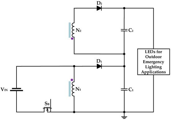
Figure 1.
The proposed LED lamp driver circuit for outdoor emergency lighting applications applied to a DC-input voltage source.
Figure 2 illustrates the equivalent circuit of the proposed DC-powered LED lamp driver, designed for outdoor emergency lighting applications, as derived through the analysis of its operational modes. To facilitate the analysis of the circuit behavior, the following assumptions are made:
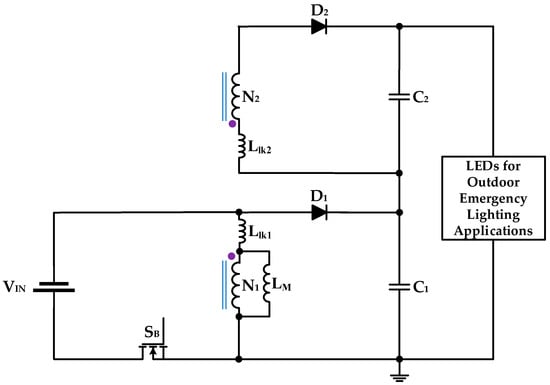
Figure 2.
Equivalent circuit of the proposed DC-powered LED lamp driver for outdoor emergency lighting applications.
(a) The magnetizing inductor LM of the transformer TR is designed to operate in continuous conduction mode (CCM). The parameters Llk1 and Llk2 represent the primary- and secondary-side leakage inductances of the transformer, respectively. It is assumed that the values of Llk1 and Llk2 are significantly smaller than LM; thus, the voltage drops across the leakage inductors can be neglected during analysis.
(b) The energy storage capacitors C1 and C2 are assumed to have sufficiently large capacitance such that the output voltage remains approximately constant. Additionally, both capacitors are assumed to have equal capacitance values.
(c) The effects of the antiparallel diode and the turn-on resistor of the power switch SB are neglected for simplification.
(d) All other circuit components are considered ideal.
Furthermore, the proposed driver circuit possesses the capability to recycle the energy stored in the transformer leakage inductances Llk1 and Llk2, thereby enhancing overall system efficiency.
Figure 3, Figure 4, Figure 5 and Figure 6 show the operating mode 1, mode 2, mode 3 and theoretical waveforms of the DC-powered LED lamp driver for outdoor emergency lighting applications, respectively, and the operational analysis is described in detail below.
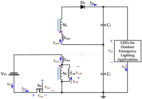
Figure 3.
Equivalent circuit diagram of operation mode 1 of the proposed DC-powered LED lamp driver circuit for outdoor emergency lighting applications.
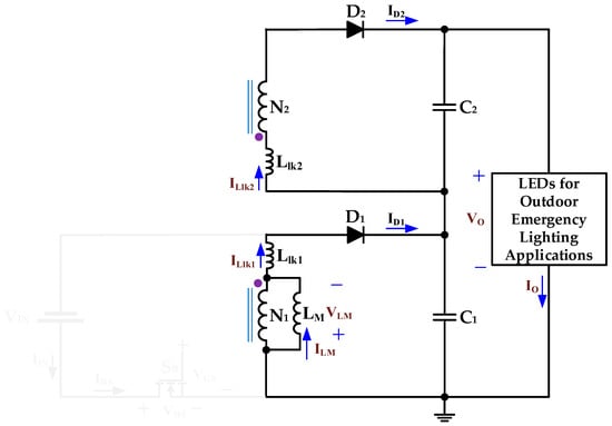
Figure 4.
Equivalent circuit diagram of operation mode 2 of the proposed DC-powered LED lamp driver circuit for outdoor emergency lighting applications.
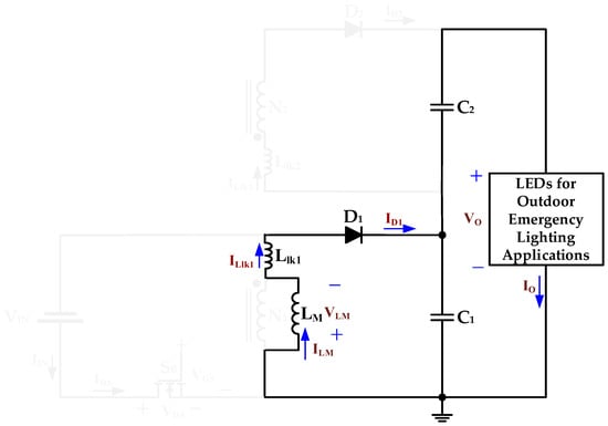
Figure 5.
Equivalent circuit diagram of operation mode 3 of the proposed DC-powered LED lamp driver circuit for outdoor emergency lighting applications.
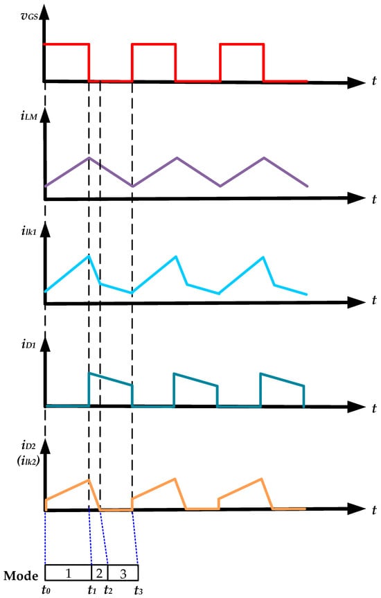
Figure 6.
Theoretical waveforms of the proposed DC-powered LED lamp driver circuit for outdoor emergency lighting applications.
Operation Mode 1 (t0 ≤ t < t1): Figure 3 presents the equivalent circuit corresponding to operation mode 1 of the proposed DC-powered LED lamp driver circuit, intended for outdoor emergency lighting applications. At the initial time instant t0, the power switch SB is turned on. During this interval, the input voltage source VIN delivers energy to both the magnetizing inductance LM and the primary-side leakage inductance Llk1 through the conducting switch SB. The voltage developed across the magnetizing inductor LM in this mode can be expressed as:
The current flow through the magnetizing inductor LM can be expressed by
During this operational interval, diode D2 is in a state of forward bias. The input voltage source VIN delivers energy to the secondary-side leakage inductor Llk2 and the output capacitor C2 via the conducting switch SB, the transformer TR, and the forward-conducting diode D2.
The current flow through the leakage inductor Llk2 can be expressed by
Concurrently, the output capacitors (C1 and C2) supply energy to the light-emitting diodes (LEDs) employed in outdoor emergency lighting applications. When the power switch SB is turned off at t1, the operation mode 1 ends.
Operational Mode 2 (t1 ≤ t < t2): Figure 4 presents the equivalent circuit corresponding to operation mode 2 of the proposed DC-powered LED lamp driver circuit, intended for outdoor emergency lighting applications. At t1, the power switch SB is off, and the magnetizing inductor LM and the primary-side leakage inductance Llk1 provide energy to the output capacitor C1 via the diode D1. In addition, the leakage inductor Llk2 delivers energy to the capacitor C2 via the diode D2. Meanwhile output capacitors C1 and C2 continuously provide energy to the LEDs for outdoor emergency lighting applications. When the leakage inductor current ILlk2 is decreased to zero at t2, operation mode 2 ends.
Operational Mode 3 (t2 ≤ t < t3): Figure 5 presents the equivalent circuit corresponding to operation mode 3 of the proposed DC-powered LED lamp driver circuit, intended for outdoor emergency lighting applications. At t2, the power switch SB is off, and the magnetizing inductor LM and the primary-side leakage inductance Llk1 provide energy to the output capacitor C1 via the diode D1. During this interval, capacitors C1 and C2 continue to provide uninterrupted energy to the LEDs, thereby ensuring stable operation of the lighting system. When the power switch SB is turned on again at t3, operation mode 3 ends and the circuit reverts to operation mode 1. In addition, it is noteworthy that the output capacitors C1 and C2 are sufficiently large to maintain a constant voltage across the LED lamp, thus guaranteeing a stable energy supply throughout the operating process.
3. Design Considerations of Some Circuit Parameters in the DC-Powered LED Lamp Driver Circuit for Outdoor Emergency Lighting Applications
3.1. Voltage Gain VOUT/VIN in the Proposed Converter
Based on the volt-second balance theorem, the voltage across the magnetizing inductor LM during the switch’s turn-on time is equal to the voltage across LM during the switch’s turn-off time. This relationship can be expressed using the following formula:
where Duty is the duty cycle of the power switches, and TS is the switching period.
By organizing Equation (4), the description of the voltage gain VOUT/VIN in the proposed converter can be given by
Figure 7 displays the voltage gains VOUT/VIN versus duty under different turn ratios NP/NS according to Equation (5).
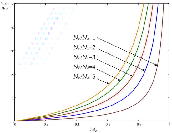
Figure 7.
The voltage gains VOUT/VIN versus duty under different turns ratio NP/NS.
3.2. Design Equation of the Magnetizing Inductor LM
The magnetization inductance LMB in the boundary mode can be expressed as follows [31].
With an output voltage VOUT of 20 volts, an NP/NS of 1, an output current IOB of 0.6 amperes, and a switching frequency fS of 50 kHz, the value of the magnetization inductance LMB in the boundary conduction mode can be calculated as
In order to operate the magnetizing inductor current in continuous conduction mode, the magnetizing inductor LM is designed to be 129 μH.
3.3. Design Equation of the Output Capacitors C1 and C2
The design expressions of output capacitors C1 and C2 can be obtained as [31]
where ΔVOUT is the peak-to-peak value of the output voltage occurred on the output capacitor.
Substituting the circuit parameters into Equation (4), with a VOUT of 20 V, an NP/NS of 1, a Duty of 0.5, a fS of 50 kHz, an LM of 129 μH, and a ΔVOUT of 0.01 V, the values of capacitors C1 and C2 can be obtained as follows:
When implementing the circuit, the output capacitors C1 and C2 are selected as 680 μF.
3.4. Description of Voltage Stress of the Power Switch
The voltage stress of the power switch used in the proposed converter are expressed by
With an input voltage of 14.8 V, Figure 8 displays the voltage stresses VDS versus duty under different turn ratios NP/NS according to Equation (8).
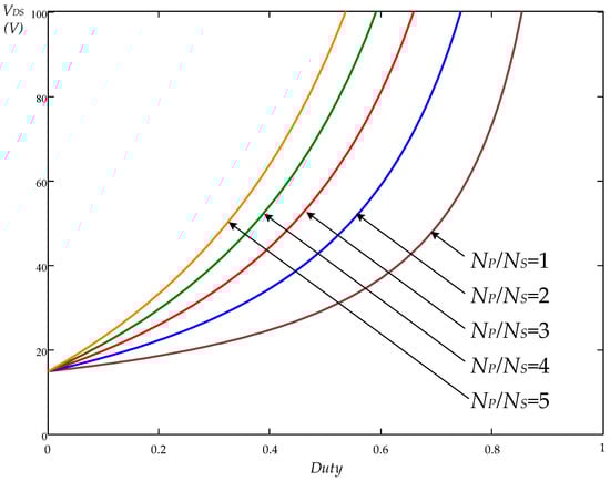
Figure 8.
The voltage stresses VDS of the switch versus duty under different turn ratios NP/NS.
4. Specification and Experimental Results Along with Loss Breakdown Analysis of Prototype DC-Powered LED Lamp Driver Circuit for Outdoor Emergency Lighting Applications
4.1. Specification and Experimental Results of Prototype DC-Powered LED Lamp Driver Circuit
A prototype DC-powered LED lamp driver circuit with a rated output power of 12 W has been successfully designed, implemented, and experimentally verified. The circuit operates from a DC input voltage of 14.8 V, delivering a regulated output voltage of 20 V and an output current of 0.6 A. The experimental LED lamp is composed of twelve light-emitting diodes (LEDs) connected in series. Each LED is characterized by a rated power of 1.2 W, a rated voltage of 2 V, and a rated current of 0.6 A. Consequently, the overall configuration yields a total rated power of 12 W, a total rated voltage of 20 V, and a total rated current of 0.6 A. The detailed electrical specifications of the proposed LED driver circuit, intended for outdoor emergency lighting applications, are summarized in Table 1. The power switch within the circuit operates at a fixed switching frequency fS of 50 kHz. The key components employed in the implementation of the proposed driver circuit are listed in Table 2. The control strategy is based on pulse-width modulation (PWM), and the PWM controller utilized is the UC3842 integrated circuit.

Table 1.
Specifications of the Proposed DC-Powered LED Lamp Driver Circuit for Outdoor Emergency Lighting Applications.
Table 2.
Key Components Used in the Proposed DC-Powered LED Lamp Driver Circuit for Outdoor Emergency Lighting Applications.
The measured gate-driving signal vGS is shown in Figure 9, clearly indicating a switching frequency of 50 kHz. Figure 10 illustrates the measured switch voltage vDS and switch current iDS of the proposed converter. Minor distortions and oscillations are observed in the waveform of vDS, which can be attributed to the absence of turn-on snubber and turn-off snubber circuits. Nevertheless, the peak value of the measured switch voltage remains relatively low, not exceeding 40 V. Similarly, the peak switch current iDS is below 3 A. These results indicate that the selected MOSFET used as the power switch in the proposed converter operates within safe voltage and current stress limits, confirming its suitability for the intended application. Figure 11 and Figure 12 present the measured currents through the leakage inductors, denoted as iLK1 and iLK2, respectively. The measured input voltage VIN and input current IIN are depicted in Figure 13, with average values of 14.96 V and 0.89 A. Similarly, the measured output voltage VOUT and output current IOUT, shown in Figure 14, exhibit average values of 20.05 V and 0.61 A.
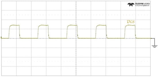
Figure 9.
Measured gate-driving signal vGS (10 V/div); time scale: 10 μs/div.
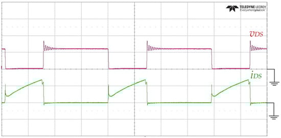
Figure 10.
Measured switch voltage vDS (20 V/div) and switch current iDS (2 A/div); time scale: 5 μs/div.
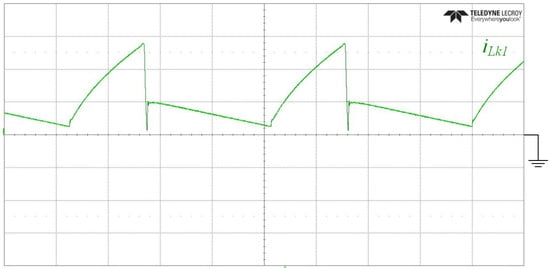
Figure 11.
Measured leakage inductor current iLK1 (1 A/div); time scale: 5 μs/div.
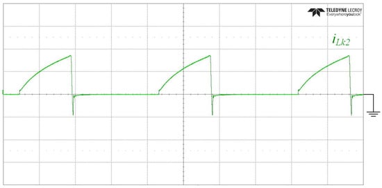
Figure 12.
Measured leakage inductor current iLk2 (1 A/div); time scale: 5 μs/div.
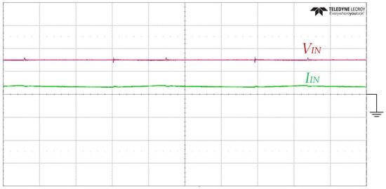
Figure 13.
Measured input voltage VIN (10 V/div) and input current IIN (2 A/div); time scale: 5 μs/div.
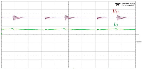
Figure 14.
Measured output voltage VO (10 V/div) and output current IO (1 A/div); time scale: 5 μs/div.
The efficiency of the proposed DC-powered LED lamp driver circuit was evaluated through both simulation and experimental analysis. Circuit simulation software was employed to estimate the input power, output power, and power dissipation, yielding values of 13.6615 W, 12.5001 W, and 1.16141 W, respectively. These results correspond to an estimated power conversion efficiency of 91.50%. Complementary to the simulation, experimental measurements were carried out, indicating an input power of 13.31 W, an output power of 12.23 W, and a power dissipation of 1.08 W. Consequently, the measured power conversion efficiency was determined to be 91.88%.
A photographic demonstration of the prototype system powering the experimental LED lamp is presented in Figure 15. The image confirms successful operation, as the LED lamp is visibly illuminated using the proposed DC-powered driver circuit. Additionally, a digital oscilloscope, in conjunction with voltage and current probes, was employed to capture and analyze the electrical waveforms of the prototype during operation.
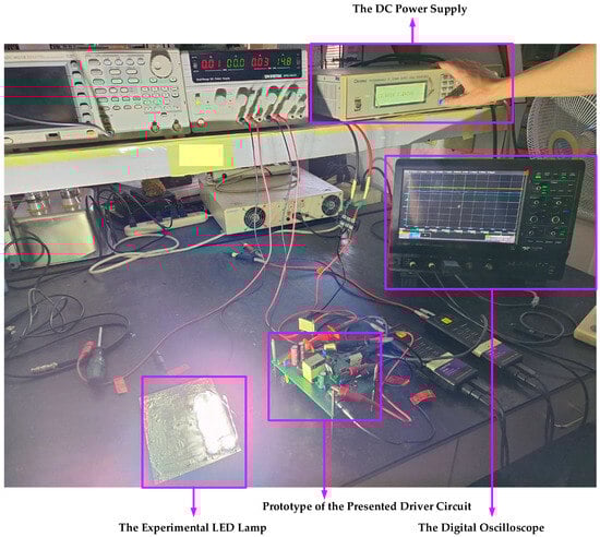
Figure 15.
Photograph of supplying the experimental LED lamp using the prototype DC-powered driver circuit.
4.2. Loss Breakdown Analysis of Prototype DC-Powered LED Lamp Driver Circuit
The analysis of loss breakdown chart in the presented LED tube lamp driver are accomplished and calculated in the following.
(1) The prototype LED lamp driver circuit exhibits a measured input power of 13.31 W. At an input voltage of 14.8 V, the proposed driver achieves a measured efficiency of 91.88%. Consequently, the total power losses within the system can be determined as follows:
(2) The equation for calculating conduction loss of the power switch SB is given by
where the IDS,mean is the mean level of the switch current iDS and the RDS,ON is the equivalent resistor when the power switch is turned on.
The average drain-source current iDS flowing through the power switch is measured to be 0.643 A. The on-state resistance RDS,ON of the employed power MOSFET (IRFP460) is specified as 0.27 Ω. Accordingly, the conduction loss associated with the power switch $S_B$ can be calculated as follows:
Additionally, the percentage of conduction loss for the power switch is given by
(3) The equation for calculating conduction loss of one power diode is given by
where the VF is the forward voltage drop of the diode and the ID,mean is the mean level of the diode current.
To evaluate the conduction loss of the power diode D1, the measured average current ID1 flowing through the diode is 0.2647 A, while the forward voltage drop Vf of the employed power diode (MUR460) is specified as 1.2 V. Therefore, the conduction loss associated with diode D1 can be calculated as follows:
Additionally, the percentage of conduction loss for the power diode D1 is given by
To evaluate the conduction loss of the power diode D2, the measured average current ID2 flowing through the diode is 0.2443 A, while the forward voltage drop Vf of the employed power diode (MUR460) is specified as 1.2 V. Therefore, the conduction loss associated with diode D2 can be calculated as follows:
Additionally, the percentage of conduction loss for the power diode D2 is given by
(4) Other losses of the LED lamp driver are given by
Additionally, the percentage of other losses is given by
Additionally, Figure 16 shows the loss breakdown chart of the presented DC-powered LED lamp driver. The percentages of conduction losses of power switch SB, power diode D1, power diode D2 and other losses are 10.33%, 29.41%, 27.15%, and 33.11%, respectively.
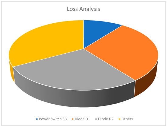
Figure 16.
The loss breakdown chart of the presented DC-powered LED lamp driver.
4.3. Stability Analysis of Prototype DC-Powered LED Lamp Driver Circuit Using a Simulation Software
The stability of a power converter can be evaluated through the use of phase margin and gain margin. A higher phase margin and gain margin generally indicate a more stable system, albeit with a slower dynamic response. Conversely, lower margins may result in a faster response but increase the risk of oscillation or instability. In this study, the stability analysis of the proposed DC-powered LED lamp driver circuit is performed using circuit simulation software. Figure 17 presents the frequency-domain analysis, specifically the bode plot, of the proposed DC-powered LED lamp driver circuit obtained from the simulation. For a power converter to exhibit satisfactory stability, it is generally recommended that the phase margin lies between 45° and 60°, and the gain margin exceeds 6 dB. Based on the data extracted from Figure 17, the phase margin and gain margin of the proposed circuit are 59.27° and 23.69 dB, respectively. These results fall within the recommended stability criteria, thereby confirming the stable operation of the proposed LED driver circuit.
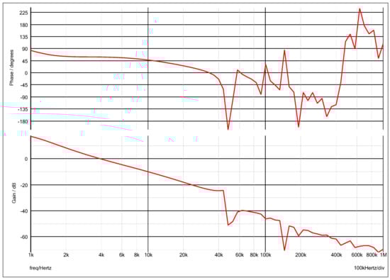
Figure 17.
Frequency-domain analysis (bode plot) of the proposed DC-powered LED lamp driver circuit obtained from the simulation.
5. Conclusions
This study has highlighted the significance of outdoor emergency lighting and emphasized the numerous advantages of employing LED technology in such applications, including energy efficiency, durability, and environmental sustainability. To address the demand for a reliable and efficient power supply system in emergency scenarios, a novel LED driver circuit was proposed. The proposed topology integrates a buck-boost converter with a flyback converter, forming a hybrid architecture capable of recovering leakage inductance energy from the transformer. This design not only enhances energy conversion efficiency but also reduces the number of power switches and associated components, thereby lowering overall system cost and complexity.
A prototype LED driver circuit with a DC input voltage of 14.8 V and a rated output of 12 W (20 V/0.6 A) was successfully designed and implemented to validate the proposed architecture. Experimental results confirm that the circuit operates with high efficiency and reliable performance, achieving a measured power conversion efficiency of 91.88%. These findings demonstrate the practicality and effectiveness of the proposed LED driver for outdoor emergency lighting applications and suggest its potential for broader adoption in energy-conscious emergency lighting systems.
Author Contributions
C.-A.C. developed topology and designed the methodology of the LED lamp driver circuit; C.-H.C., H.-L.C. (Hung-Liang Cheng) and E.-C.C. set up the simulation software and performed simulations of the LED lamp driver circuit; H.-J.H., J.-H.D., H.-L.C. (Hsiang-Lin Chang) and P.-Y.Y. carried out the prototype LED lamp driver circuit, and measured as well as analyzed experimental results with the guidance from C.-A.C.; C.-A.C. and E.-C.C. prepared the first draft of the article and revised the manuscript for submission. All authors have read and agreed to the published version of the manuscript.
Funding
The authors would like to express their greatest and sincerest thanks to National Science and Technology Council (NSTC) of Taiwan for its grant numbers NSTC 113-2813-C-214-021-E and NSTC 113-2221-E-214-020.
Data Availability Statement
Data are contained within the article.
Conflicts of Interest
The authors declare no conflicts of interest.
References
- Abdelmoumene, A.; Bentarzi, H.; Iqbal, A.; Krama, A. Developments and trends in emergency lighting systems: From energy-efficiency to zero electrical power consumption. Life Cycle Reliab. Saf. Eng. 2024, 13, 129–145. [Google Scholar] [CrossRef]
- Narasimha, S.; Salkuti, S.R. Design and Development of Smart Emergency Light. Telkomnika Telecommun. Comput. Electron. Control 2020, 18, 358–364. [Google Scholar] [CrossRef]
- Xu, W.; Kim, J.Y.; Huang, W.; Kanhere, S.S.; Jha, S.K.; Hu, W.; Misra, P. A Novel Emergency Light Based Smart Building Solution: Design, Implementation, and Use Cases. In Proceedings of the 2022 IEEE 19th International Conference on Mobile Ad Hoc and Smart Systems (MASS), Denver, CO, USA, 20–22 October 2022; pp. 577–585. [Google Scholar]
- Kiwan, S.; Abo Mosali, A.; Al-Ghasem, A. Smart Solar-Powered LED Outdoor Lighting System Based on the Energy Storage Level in Batteries. Buildings 2018, 8, 119. [Google Scholar] [CrossRef]
- AlRuwais, S.; AlQahtani, R.; AlHajri, N.; AlHashim, B.; Bashar, A.; AlZubaidi, L. S-LIGHT: Smart LED Lamppost using PWM-based Adaptive Light Controller. In Proceedings of the 2021 10th IEEE International Conference on Communication Systems and Network Technologies (CSNT), Bhopal, India, 18–19 June 2021; pp. 325–331. [Google Scholar]
- Cheng, Y.; Fang, C.; Yuan, J.; Zhu, L. Design and Application of a Smart Lighting System Based on Distributed Wireless Sensor Networks. Appl. Sci. 2020, 10, 8545. [Google Scholar] [CrossRef]
- Primiceri, P.; Visconti, P. Solar-powered LED-based lighting facilities: An overview on recent technologies and embedded IoT devices to obtain wireless control, energy savings and quick maintenance. ARPN J. Eng. Appl. Sci. 2017, 12, 140–150. [Google Scholar]
- Zhou, Y.; Li, G. Design and Fabrication of Multifunctional Portable Bi2Te3-Based Thermoelectric Camping Lamp. J. Electron. Mater. 2018, 47, 4090–4097. [Google Scholar] [CrossRef]
- Chinchero, H.F.; Alonso, J.M.; T, H.O. LED lighting systems for smart buildings: A review. IET Smart Cities 2020, 2, 126–134. [Google Scholar] [CrossRef]
- Lozano-Miralles, J.A.; Hermoso-Orzáez, M.J.; Gago-Calderón, A.; Brito, P. LCA Case Study to LED Outdoor Luminaries as a Circular Economy Solution to Local Scale. Sustainability 2020, 12, 190. [Google Scholar] [CrossRef]
- Kerbiriou, C.; Barré, K.; Mariton, L.; Pauwels, J.; Zissis, G.; Robert, A.; Le Viol, I. Switching LPS to LED Streetlight May Dramatically Reduce Activity and Foraging of Bats. Diversity 2020, 12, 165. [Google Scholar] [CrossRef]
- Robles, J.; Zamorano, J.; Pascual, S.; Sánchez de Miguel, A.; Gallego, J.; Gaston, K.J. Evolution of Brightness and Color of the Night Sky in Madrid. Remote Sens. 2021, 13, 1511. [Google Scholar] [CrossRef]
- Arias, M.; Lamar, D.G.; Linera, F.F.; Balocco, D.; Diallo, A.A.; Sebastián, J. Design of a Soft-Switching Asymmetrical Half-Bridge Converter as Second Stage of an LED Driver for Street Lighting Application. IEEE Trans. Power Electron. 2011, 27, 1608–1621. [Google Scholar] [CrossRef]
- Alharbi, F.; Almoshaogeh, M.I.; Ibrahim, A.H.; Haider, H.; Elmadina, A.E.M.; Alfallaj, I. Performance Appraisal of Urban Street-Lighting System: Drivers’ Opinion-Based Fuzzy Synthetic Evaluation. Appl. Sci. 2023, 13, 3333. [Google Scholar] [CrossRef]
- Muneer, A.; Fayyaz, A.; Iqbal, S.; Jabbar, M.W.; Qaisar, A.; Farooq, F. Single Stage Active Power Factor Correction Circuit for Street LED Light with Battery Backup. Eng. Proc. 2021, 12, 69. [Google Scholar]
- Kolla, H.R.; Vishwanathan, N.; Murthy, B.K. Independently Controllable Dual-Output Half-Bridge Series Resonant Converter for LED Driver Application. IEEE J. Emerg. Sel. Top. Power Electron. 2021, 10, 2178–2189. [Google Scholar] [CrossRef]
- Deshpande, T.; Das, S.; Chavan, H.; Hangloo, A.K.; Jadhav, S. Solar Powered LED Street Lighting with Digital Control for Dimming operation. In Proceedings of the 2021 4th Biennial International Conference on Nascent Technologies in Engineering (ICNTE), Navi Mumbai, India, 15–16 January 2021; pp. 1–5. [Google Scholar]
- George Allwyn, R.; Al Abri, R.; Malik, A.; Al-Hinai, A. Economic Analysis of Replacing HPS Lamp with LED Lamp and Cost Estimation to Set Up PV/Battery System for Street Lighting in Oman. Energies 2021, 14, 7697. [Google Scholar] [CrossRef]
- Zhang, Y.; Ma, D. A Single-Stage Solar-Powered LED Display Driver Using Power Channel Time Multiplexing Technique. IEEE Trans. Power Electron. 2014, 30, 3772–3780. [Google Scholar] [CrossRef]
- Kathiresan, R.; Xiong, T.M.; Panda, S.K.; Das, P.; Reindl, T. A non-isolated converter design with time-multiplexing control topology for un-binned high-power LEDs in parallel operation for off-grid solar-PV streetlamps. In Proceedings of the 2016 IEEE International Conference on Sustainable Energy Technologies (ICSET), Hanoi, Vietnam, 14–16 November 2016; pp. 359–363. [Google Scholar]
- Xu, H.; Wen, H.; Li, X. Design and evaluation of a solar based single inductor multiple outputs LED lighting. In Proceedings of the International Conference on Renewable Power Generation (RPG 2015), Beijing, China, 17–18 October 2015; pp. 1–5. [Google Scholar]
- Ocenasek, J.; Bednar, B.; Tyrpekl, M.; Michalik, J.; Kosan, T. Design of Two-Channel LED Stand-Alone Solar Lamp Driver Prototype for Biodynamic Application. In Proceedings of the 2022 IEEE 20th International Power Electronics and Motion Control Conference (PEMC), Brasov, Romania, 25–28 September 2022; pp. 691–696. [Google Scholar]
- Ramprasad, S.; Raj, S.; Wei, H.J.; Wong, J.K.C.; Mueller, T.; Aberle, A.G. Implementation of a novel LED based light soaking system for solar cell characterisation. In Proceedings of the 2018 IEEE 7th World Conference on Photovoltaic Energy Conversion (WCPEC) (A Joint Conference of 45th IEEE PVSC, 28th PVSEC & 34th EU PVSEC), Waikoloa, HI, USA, 10–15 June 2018; pp. 2234–2236. [Google Scholar]
- Chen, Y.; Nan, Y.; Kong, Q. A Loss-Adaptive Self-Oscillating Buck Converter for LED Driving. IEEE Trans. Power Electron. 2012, 27, 4321–4328. [Google Scholar] [CrossRef]
- Corradini, L.; Spiazzi, G. A High-Frequency Digitally Controlled LED Driver for Automotive Applications With Fast Dimming Capabilities. IEEE Trans. Power Electron. 2014, 29, 6648–6659. [Google Scholar] [CrossRef]
- Pollock, A.; Pollock, H.; Pollock, C. High Efficiency LED Power Supply. IEEE J. Emerg. Sel. Top. Power Electron. 2015, 3, 617–623. [Google Scholar] [CrossRef]
- Luewisuthichat, K.; Boonprasert, P.; Ekkaravarodome, C.; Bilsalam, A. Analysis and Implement DC-DC Integrated Boost-Flyback Converter with LED Street Light Stand-by Application. In Proceedings of the 2020 International Conference on Power, Energy and Innovations (ICPEI), Chiangmai, Thailand, 14–16 October 2020; pp. 197–200. [Google Scholar]
- Pouladi, F.; Farzanehfard, H.; Adib, E.; Le Sage, H. Single-Switch Soft-Switching LED Driver Suitable for Battery-Operated Systems. IEEE Trans. Ind. Electron. 2018, 66, 2726–2734. [Google Scholar] [CrossRef]
- Divya, K.M.; Parackal, R. High power factor integrated buck-boost flyback converter driving multiple outputs. In Proceedings of the 2015 Online International Conference on Green Engineering and Technologies (IC-GET), Coimbatore, India, 27 November 2015; pp. 1–5. [Google Scholar]
- Cheng, C.-A.; Chang, C.-H.; Cheng, H.-L.; Chang, E.-C.; Du, J.-H.; Huang, H.-J.; Ye, P.-Y.; Chang, H.-L. A DC-Powered LED Driver Circuit for Outdoor Emergency Lighting Applications. In Proceedings of the 2025 IEEE International Conference on Consumer Electronics, Kaohsiung, Taiwan, 16–18 July 2025; pp. 1–2. [Google Scholar]
- Cheng, C.-A.; Chang, C.-H.; Cheng, H.-L.; Chang, E.-C.; Yan, W.-Y.; Lan, L.-F. A UV-C LED Lamp Driver Circuit Applied to a Direct-Current-Input Voltage Source for Sterilization and Germicidal Applications. Appl. Sci. 2025, 15, 1498. [Google Scholar] [CrossRef]
Disclaimer/Publisher’s Note: The statements, opinions and data contained in all publications are solely those of the individual author(s) and contributor(s) and not of MDPI and/or the editor(s). MDPI and/or the editor(s) disclaim responsibility for any injury to people or property resulting from any ideas, methods, instructions or products referred to in the content. |
© 2025 by the authors. Licensee MDPI, Basel, Switzerland. This article is an open access article distributed under the terms and conditions of the Creative Commons Attribution (CC BY) license (https://creativecommons.org/licenses/by/4.0/).