1. Introduction
Reinforced concrete (RC) frame structures with unreinforced masonry infill walls represent one of the most universal structural systems employed globally for both residential and commercial buildings. Their widespread application is largely attributed to the cost-effectiveness, ease of construction, and flexibility in architectural layout offered by masonry infill panels, which are frequently used to define both internal partitions and building façades. However, despite their structural relevance, infill panels are often classified as non-structural elements in contemporary seismic codes—such as Eurocode 8, ASCE 7, and numerous national design standards—leading to their exclusion from the analytical seismic demand and capacity evaluations of RC frame systems.
A substantial body of experimental and numerical research [
1,
2,
3,
4,
5,
6,
7,
8,
9,
10,
11,
12,
13,
14,
15,
16,
17,
18,
19,
20,
21,
22,
23,
24,
25,
26,
27] has demonstrated that unreinforced masonry infill walls significantly influence the seismic behavior of RC frames. Due to their inherent in-plane stiffness and strength, these panels act as unintended diagonal compression struts under lateral loading, substantially modifying the lateral load distribution, stiffness, and failure mechanisms of the host structure. This infill–frame interaction may result in stress concentrations, shear failures, and the formation of weak or soft stories, particularly in structures lacking proper seismic detailing. These adverse effects are especially pronounced in non-seismically designed frames, where the irregular distribution of infills across stories further exacerbates lateral deformation demands.
Moreover, the out-of-plane behavior of masonry infill panels is a critical factor often overlooked in both analysis and design [
28]. During seismic events, infills are simultaneously subjected to in-plane racking forces and out-of-plane inertial forces, leading to complex stress states and potential for out-of-plane instability. Empirical studies [
29,
30,
31] have shown that panels with insufficient anchorage to surrounding frames are particularly susceptible to detachment or collapse, posing severe safety hazards to occupants and bystanders.
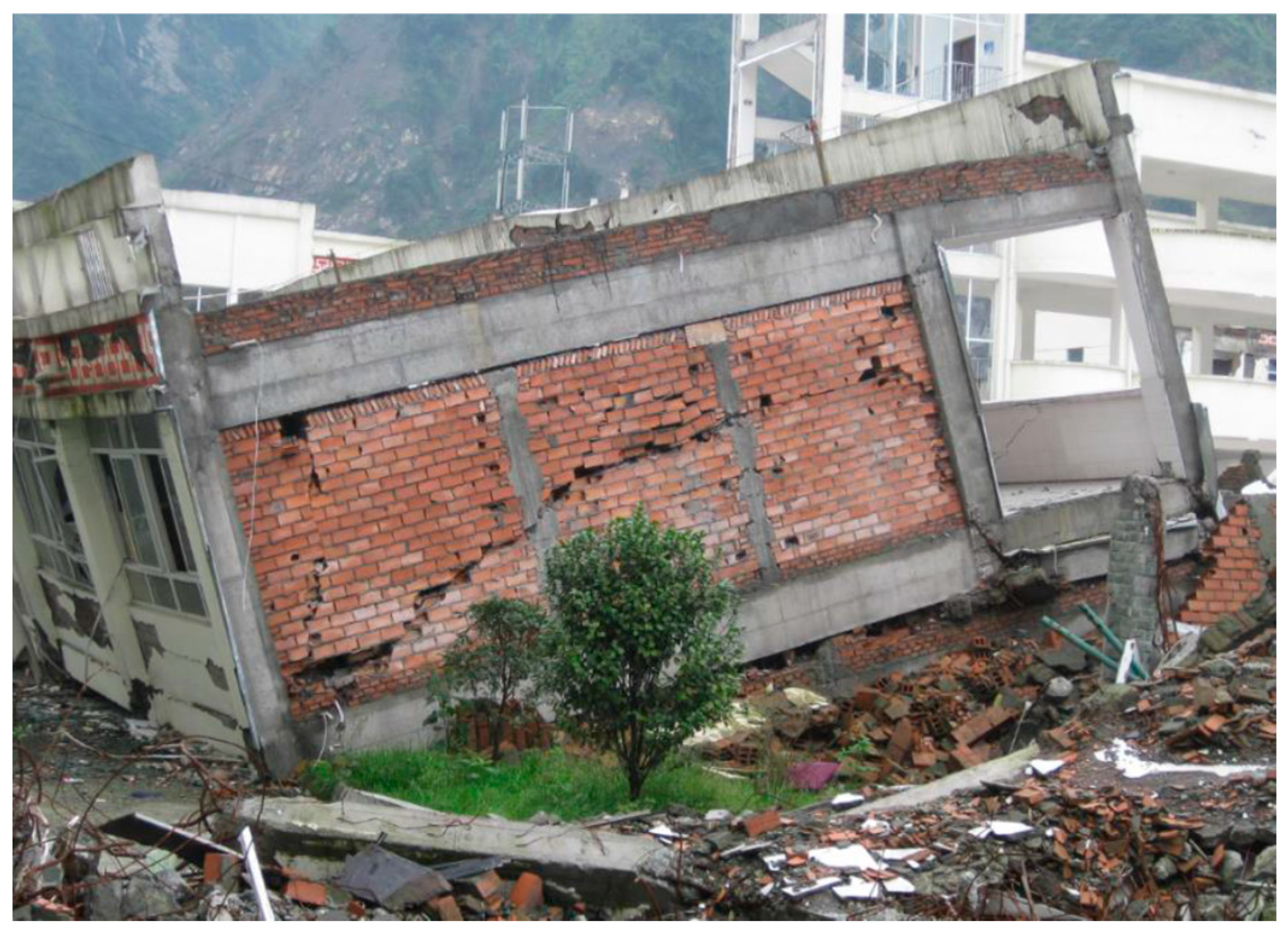
This vulnerability was starkly demonstrated during the 2023 Kahramanmaraş earthquake sequence in Türkiye, which included two major mainshocks of Mw 7.7 and Mw 7.6 occurring within hours of each other. Post-earthquake reconnaissance efforts documented extensive damage to RC frame structures with URM infills throughout affected cities such as Kahramanmaraş, Hatay, Gaziantep, and Adıyaman. Observed failure modes included diagonal cracking, corner crushing, and disintegration of infill panels, with many cases of partial or complete out-of-plane collapse. In particular, buildings with open ground stories or irregular infill distribution experienced severe soft-story mechanisms, leading to collapse. These findings are consistent with previous seismic events—such as the 1999 Kocaeli (Türkiye), 2008 Wenchuan (China), presented in
Figure 1, 2010 Maule (Chile), 2009 L’Aquila, and 2016 Central Italy earthquakes—where infill-related failures significantly contributed to structural damage and life loss.
In addition to complete collapses, a considerable number of otherwise structurally intact RC frames experienced infill panel dislodgement and detachment during the Kahramanmaraş events. These non-structural failures were responsible for injuries and fatalities, as well as long-term post-earthquake functional disruptions due to debris hazards and environmental exposure. This phenomenon highlights the inadequacy of current seismic design provisions, which often neglect both the beneficial and detrimental roles of masonry infills under strong ground motion.
The Skopje earthquake of 11 September 2016 (Mw 5.0), though of lower magnitude, produced similar damage patterns in URM-infilled RC buildings, emphasizing that even moderate seismic events can expose significant vulnerabilities in this structural typology.
In light of these cumulative findings, there is a critical need for the revision of seismic design codes to incorporate the effects of infill-frame interaction, both in-plane and out-of-plane. Analytical models that account for nonlinear infill behavior, combined with construction practices aimed at mitigating infill-related damage (e.g., use of engineered infill panels, seismic gaps, and anchorage detailing) are essential to improving the seismic resilience of RC frame structures worldwide.
Despite the wealth of empirical data and post-earthquake assessments accumulated over the past several decades, the seismic performance of reinforced concrete (RC) frame structures with unreinforced masonry (URM) infill panels remains insufficiently addressed within current engineering practice. The discrepancy between predicted structural responses from conventional computational models and actual behavior observed in real-world earthquakes remains a critical and unresolved issue in structural engineering. This persistent gap arises, in part, from the absence of a unified design framework that accurately captures the complex mechanical interaction between infills and bounding RC frames. As of today, there exists no internationally standardized database or consensus-based guidelines that enable engineers to reliably quantify or predict the role of infill walls under seismic excitation. Consequently, the lack of robust data hampers the development of rational retrofitting and strengthening strategies, as noted in [
5].
Seismic design philosophy is fundamentally governed by two performance objectives: (i) preventing structural collapse under design-level seismic action—corresponding to the Ultimate Limit State (ULS)—thus ensuring life safety; and (ii) limiting structural and non-structural damage under frequent, lower-intensity earthquakes—defined by the Serviceability Limit State (SLS)—to maintain building functionality and minimize repair costs. These dual objectives are formally embedded in the provisions of Eurocode 8, [
32], which also introduces prescriptive requirements for non-structural components, including masonry infills.
Specifically, Article 4.3.6.4 of Eurocode 8 Part 1 mandates that brittle failure mechanisms in infill panels be mitigated through measures such as light wire mesh or bed-joint reinforcement. However, beyond this general recommendation, the code does not provide sufficient procedural or analytical guidance to enable practicing engineers to incorporate infill panels into seismic design and analysis models in a consistent or performance-based manner. This shortcoming limits the engineer’s ability to accurately represent the infill’s influence, particularly under nonlinear seismic demands.
In the context of new buildings, Eurocode 8 treats infill panels conservatively—as a potential source of strength and stiffness—without allowing for reduction of input seismic action due to beneficial infill effects. As a result, the design of masonry-infilled RC frames according to EC8 tends to be overly cautious, often requiring increased reinforcement in structural members compared to equivalent bare frames. While this conservatism enhances safety, it leads to inefficiencies and does not reflect the actual seismic contribution of infill panels. To advance toward a more rational and performance-based design methodology, two key provisions must be considered:
Masonry infill panels should be explicitly included in analytical models used for seismic design, recognizing their nonlinear, potentially brittle behavior.
The seismic performance of infill walls should be evaluated against structural demands derived from nonlinear time-history or pushover analyses.
The challenge becomes even more pronounced when dealing with the seismic assessment of existing RC buildings, many of which were not designed according to modern seismic standards. In such structures, the presence of infill walls often plays a dominant role in resisting lateral loads—especially in substandard RC frames with low ductility or inadequate detailing, as commonly found in Southern Europe and the broader Mediterranean region. As noted by Nechevska-Cvetanovska et al. [
33], the failure to account for infill effects in these vulnerable building stocks has contributed to widespread damage and collapse in past earthquakes, revealing a critical weakness in both design and assessment methodologies.
To address these deficiencies, the development of comprehensive, experimentally validated modeling strategies—combined with codified design and retrofit procedures for infill walls—is essential. Such advances would enable engineers to achieve both structural safety and economic efficiency in seismic design, in alignment with modern performance-based engineering principles.
The main objective of this research is to propose and test an innovative method for the column-infill connection, minimizing unexpected seismic damage and provide optimal solutions and design recommendations for masonry infilled RC frame structures in seismic prone areas. As recommended by previous researchers [
6,
14], the presence of little reinforcement significantly improves the response of a single infilled frame, particularly for what concern damage limit states. With this optimal solution by including reinforcement technique in the connection of the infill, the RC frame column members are protected from premature shear failure and tend to deform as initially designated in the design, while providing favorable integrity and in-plane stability of the infill panels. The proposed detailing method will achieve optimal and favorable force-displacement behavior between a fully infilled RC frame and a bare frame and most significant it is a simple solution which can be easily implemented in every construction environment. The complicated failure modes of tight-fit infill panels dominated by a large number of interacting parameters, and the dangerous soft/weak story phenomenon are also anticipated to be solved.
More specifically, the goals of the research are as follows:
- -
To design and construct scaled RC frame models based on the seismic code of practice and rigorous similitude requirements. To design and validate experimental instrumentation and test protocols.
- -
To investigate the effectiveness of the proposed innovative seismic damage mitigation detailing method by conducting shake-table tests on scaled three-story two-bay specimens.
- -
To propose design guidelines identifying the advantage of the proposed connection system and make intro towards design recommendations for infilled reinforced concrete frames.
The distinguished features of the proposed IW-SB Model are three-fold:
(i) it employs a pre-defined horizontal steel-bar layout along the wall height, ensuring a uniform and predictable enhancement of the panel’s in-plane and out-of-plane response;
(ii) at the interface with the RC frame, anchor bars are placed in drilled holes within the columns (short anchor dowels are hammered in) and lapped with a continuous exterior tie bar; a layer of cementitious mortar is added along the length of the wall at each location, creating a confined embedment that transfers forces to the frame and minimizes slip—an improvement over bed-joint or near-surface-mounted solutions that rely solely on bond; and
(iii) the technique is supported by a straightforward construction protocol requiring only drilling, dowel insertion, and mortar packing, making it readily deployable in low-technology or resource-constrained settings.
2. Innovative Method for Improvement of Seismic Resistance of Masonry Infill Walls in Rc Frame Structures
The research project was focused on the development and upgrading of a method for increasing the seismic capacity of reinforced concrete building structures with masonry infills. To this end, a comprehensive experimental program consisting of the following activities was realized:
laboratory testing of concrete, steel, masonry unit (bricks) specimens for definition of their strength characteristics, which are presented in detail in the work of [
34,
35];
quasi-static testing of different types of masonry wall samples for definition of mechanical characteristics and failure mechanisms;
construction of models of a three story RC building with different types of masonry infill, to a scale of 1:2.5 and preparation for shake-table testing;
shake-table testing of scaled models applying a program of experimental tests including gradual increase of intensity of input earthquake excitation, aimed at monitoring the progressive development of cracks (damages) and the phases of dynamic behavior of the models. Even though previous shake tables have been performed dealing with infill walls in RC building structures as given in [
14,
28], the presented work is oriented to results obtained from the shake-table tests of the innovative low-cost method for connection of the infill, which is significant contribution to the research topic.
In the research, the models from the experimental investigations which were performed in the frames of the research project “Frame—Masonry Composites for Modeling and Standardizations (FRAmed-MAsonry)” realized by the Faculty of Civil Engineering and Architecture, Osijek, Josip Juraj Strossmayer University of Osijek, Croatia, and the Institute of Earthquake Engineering and Engineering Seismology were used as referenced models. The project was realized in the period between September 2014 and August 2017 (Necevska Cvetanovska et al. 2015) [
33].
The referenced models are given in
Figure 2. The height of the models was 3.9 m. Model 1 structure consisted of hollow-clay infill walls, while the Model 2 structure was composed of solid-clay infill walls. The total weight of Model 1 was 29,200 kg, while that of Model 2 was 30,600 kg [
34].
2.1. Quasi-Static Tests on Masonry Panels
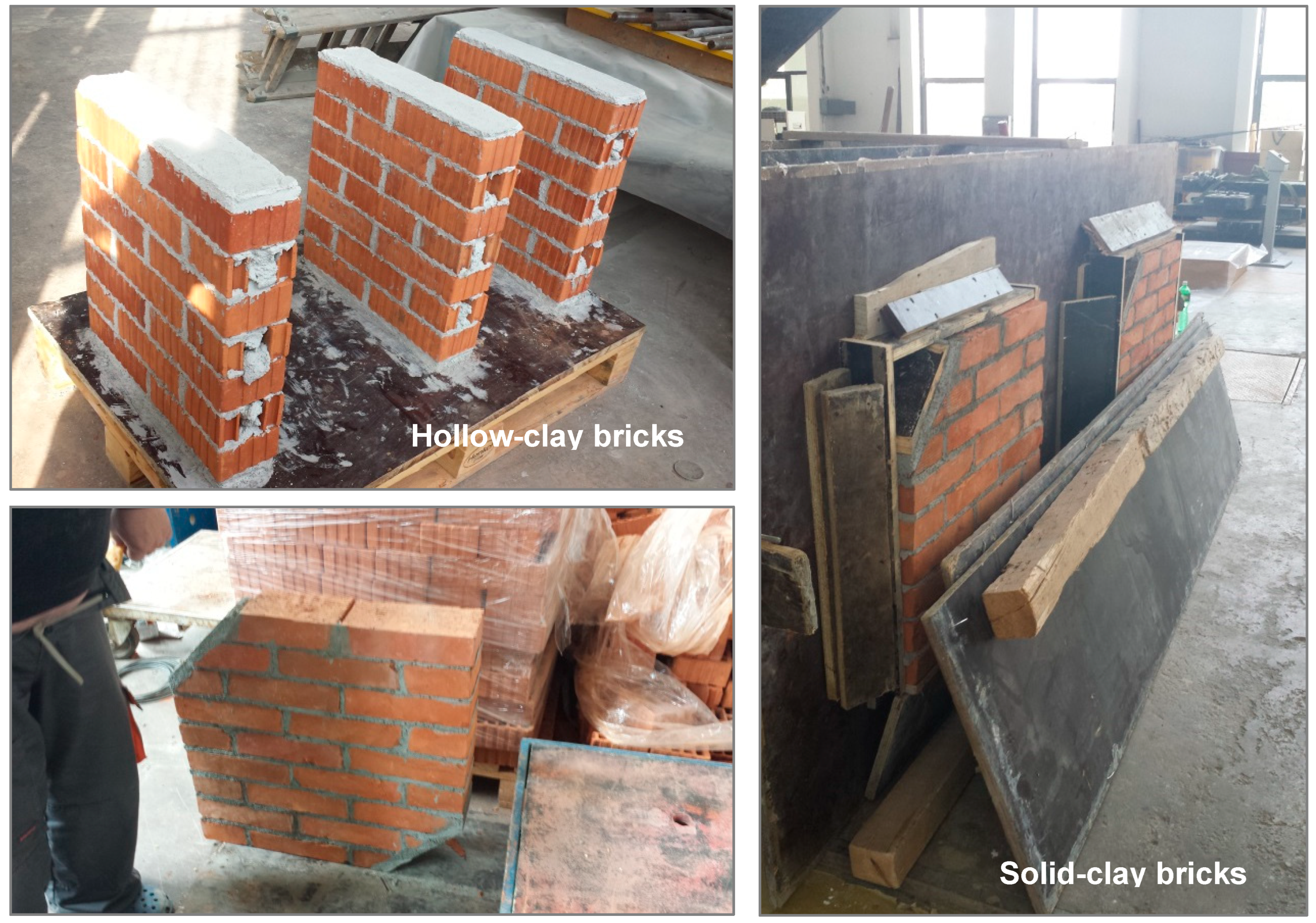
In order to evaluate the mechanical properties, load-bearing capacity, and failure mechanisms of masonry wall systems, a comprehensive series of quasi-static tests was conducted on two types of masonry configurations. The experimental program comprised two groups of six wall specimens each, constructed using cement-lime mortar. The first group consisted of walls made from hollow-clay masonry units, while the second group utilized solid-clay brick masonry.
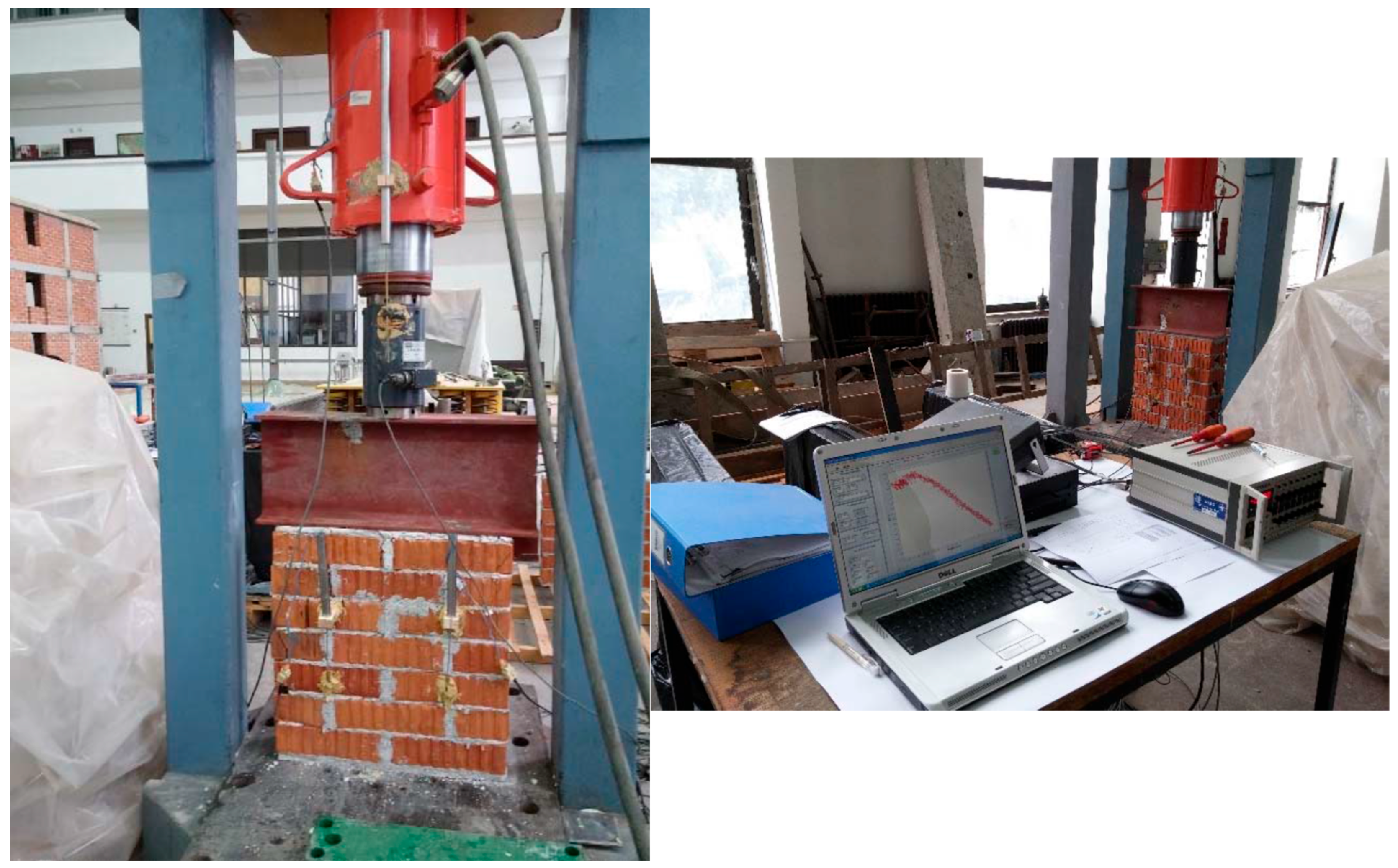
Prior to analytical modeling, all twelve wall specimens were constructed under controlled laboratory conditions at the Dynamic Testing Laboratory of the Institute of Earthquake Engineering and Engineering Seismology (IZIIS), as illustrated in
Figure 3. The quasi-static testing methodology offered a key advantage: it enabled high-precision control of loading protocols and allowed for detailed observation and documentation of damage evolution, crack propagation, and failure modes.
However, a recognized limitation of this testing approach is the absence of dynamic loading effects, which are critical to replicating the inertial forces and strain-rate-dependent responses typical of real seismic events. Despite this constraint, the experimental campaign provided essential insights into the in-plane behavior of masonry wall assemblies and served as a foundational step for subsequent analytical and numerical modeling.
Based on the carried out experimental quasi-static tests on wall elements performed at IZIIS Lab, the following is concluded:
- -
The average characteristics compressive strength of the hollow-clay masonry units was 1.50 MPa and average characteristics tensile and shear strength were 0.05 MPa and 0.08 MPa, accordingly.
These results from these quasi-static tests are prerequisite for correct further analysis of the scaled model as well as for interpretation of the model behavior.
Two basic types of wall element built from hollow-clay were tested in the considered case (
Table 1). Two distinct testing protocols were employed to characterize the mechanical response of the masonry wall specimens. The first set of specimens was subjected to uniaxial compressive loading to evaluate their behavior under axial stress conditions (
Figure 4). The second set underwent diagonal compression testing, commonly referred to as the shear or diagonal tensile test, to assess the in-plane shear capacity and failure modes (
Figure 5).
All tests were conducted either until the onset of cracking or the complete failure of the specimen, depending on the observed behavior. In addition to the applied axial or diagonal force, the displacement of the loading actuator in the direction of force application was continuously monitored. A comprehensive instrumentation setup was implemented to capture all relevant response parameters, including force–displacement relationships, crack initiation points, and deformation patterns, ensuring accurate and detailed characterization of the mechanical performance of the tested masonry assemblies.
- b.
Instrumentation
Instrumentation of the masonry wall specimens was designed and implemented in alignment with the specific objectives and testing protocols of the experimental program. A dedicated load cell was employed to measure the applied axial or diagonal force, while multiple channels were allocated to record relative displacements using Linear Variable Differential Transformers (LVDTs) positioned at strategically selected locations on each specimen.
This configuration enabled the acquisition of detailed displacement profiles and provided insight into the deformation behavior and crack development of the wall elements under loading. The relative displacements recorded at characteristic points facilitated the experimental determination of key strength parameters and stiffness properties of the masonry assemblies. Representative results and observed behavioral patterns from the tested specimens are presented and discussed in the subsequent sections.
- c.
Tests on panels from hollow-clay masonry units
Within this testing program six wall elements were subjected to monotonous increase of the force amplitude up to total failure of the elements. The compressive strength of hollow-clay masonry wall samples (W1, W2 and W3) was determined using the procedure established on the EN 1052-1:2004 standard and the referent tensile strength of hollow-clay masonry walls (W4, W5, and W6) was determined using the procedure established on the American ASTM E519/E519M-10 standard. The average characteristics compressive strength was 1.50 MPa (
Figure 6) and average characteristics tensile and shear strength were 0.05 MPa and 0.08 MPa, accordingly (
Figure 7).
2.2. Design and Construction of Model with Innovative Infill Connection (Model IW-SB)
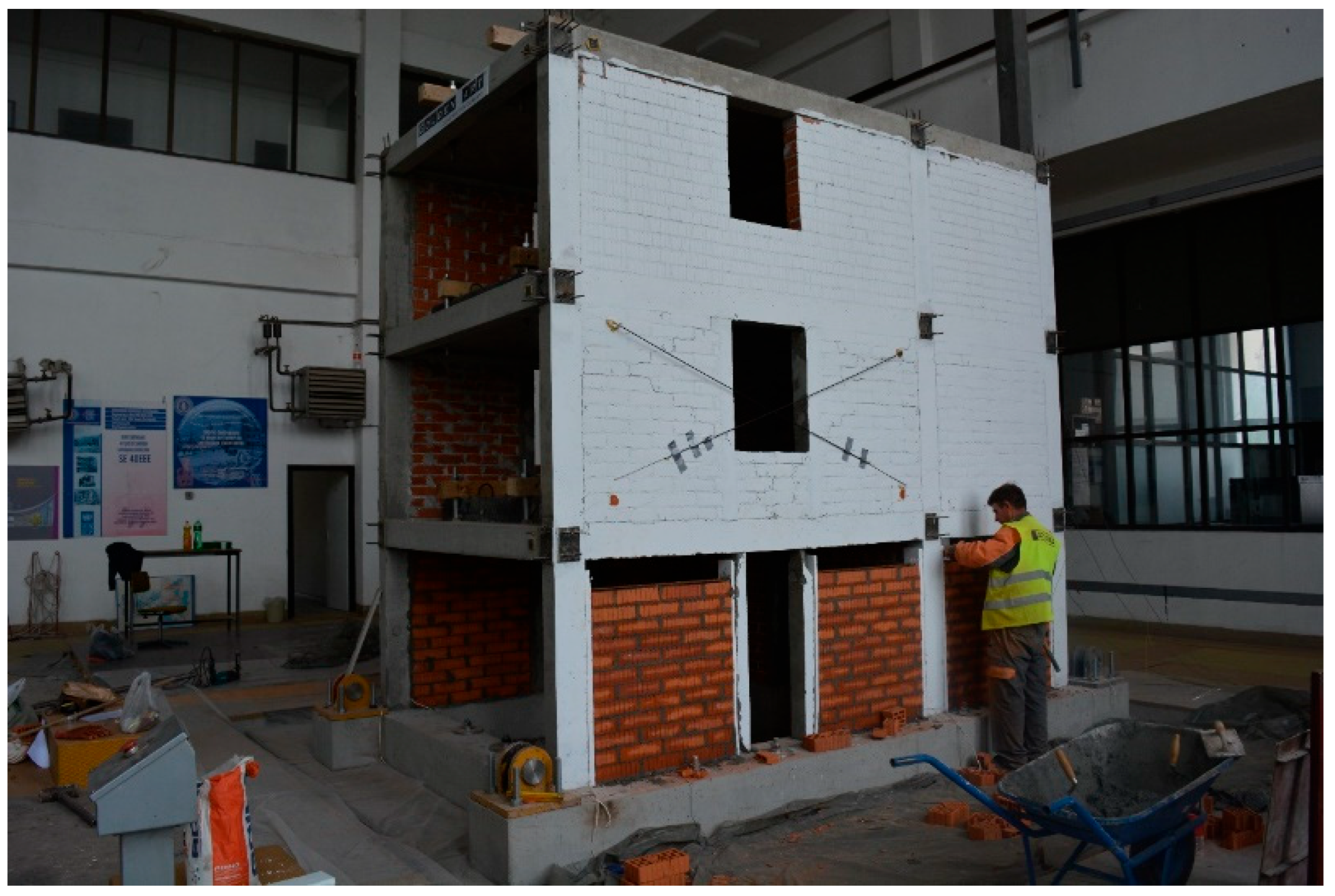
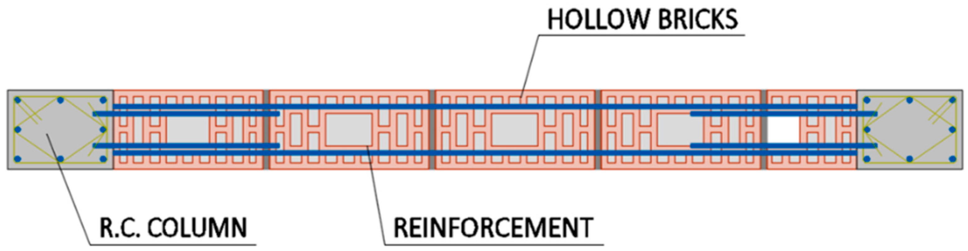
For the purpose of the presented research, a third IW-SB (Infill Wall—Steel Bars) model was designed and tested. The third model (
Figure 8) was built using the same reinforced concrete frame structure of Model 1 and Model 2, and an innovative method was introduced for the connection of the masonry infill to the structure (
Figure 9). The proposed technical solution consists of the connection of the infill panel with bounding columns with steel reinforcement connections, which are deployed in mortar layers and anchored to columns.
Figure 9 represents a cross-section of the proposed connection method. The proposed simple connection is practical, cheap, and easy to implement without any specific technology, which is very important for developing countries in seismic regions such as N. Macedonia.
While the first two models, namely, Model 1 and Model 2, were fully infilled by a masonry wall; in the third Model IW-SB, the proposed connection between the columns and the infill walls was introduced. They were connected by spaced mild steel bars without a gap between the infill and the frame and using steel reinforcement (
Figure 9).
A tailor-made experimental program was used to investigate whether the proposed column-infill connection details can effectively improve the seismic performance of masonry-infilled RC frame structures. In addition, the displacement ductility and energy dispassion capacity of the RC frame system with masonry infill was taken into consideration.
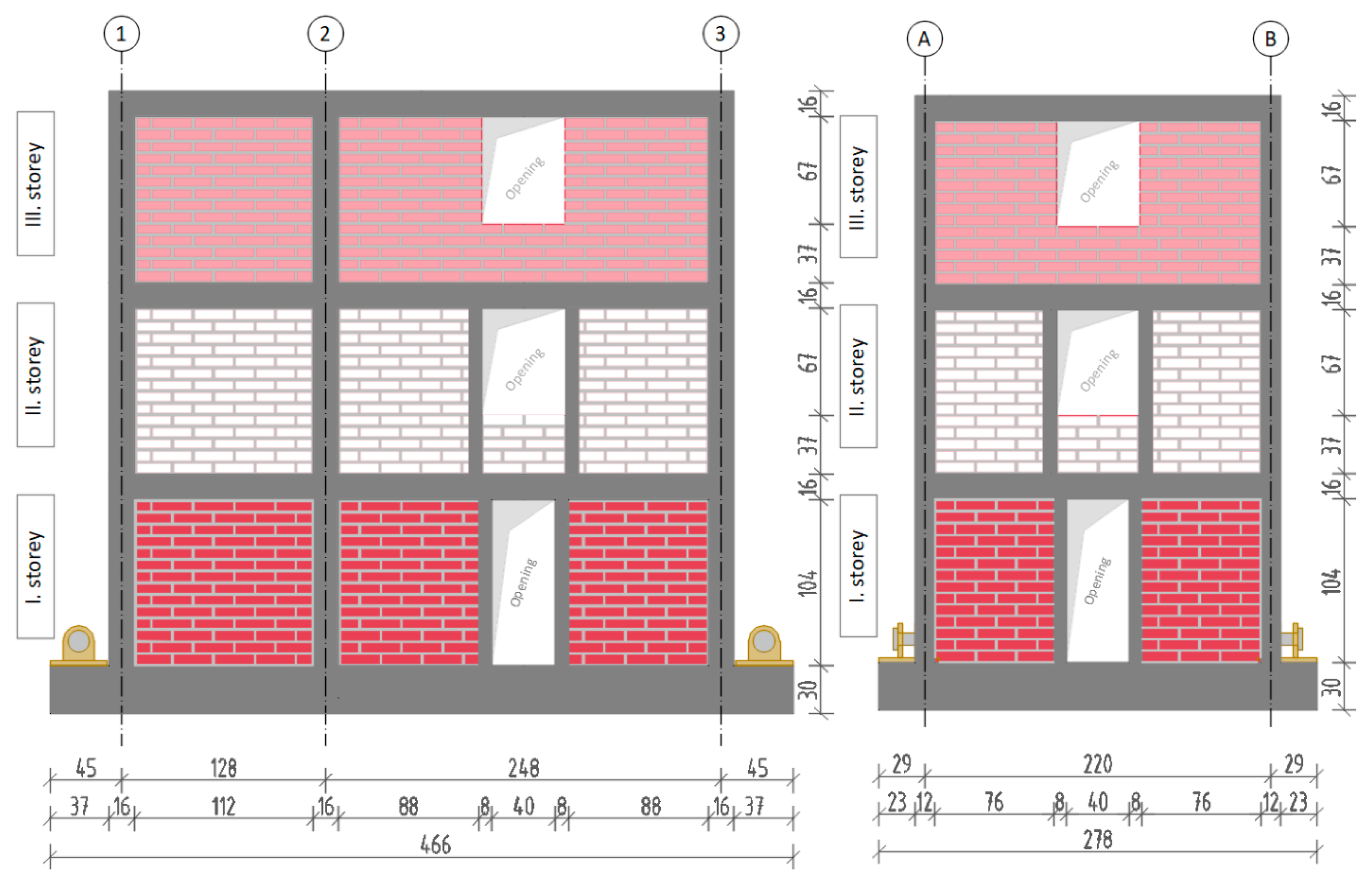
The three-dimensional reinforced concrete (RC) frame specimen, designated as Model IW-SB, was composed of two parallel, planar RC frames located along axes A and B, each infilled with hollow-clay brick masonry panels. These frames were interconnected in the orthogonal direction by transverse RC girders positioned along axes 1, 2, and 3, forming a spatial structural system (
Figure 10 and
Figure 11). Additionally, the frame aligned with axis 2 was infilled using the same hollow-brick masonry units to ensure uniformity of the bounding system.
The infill walls were constructed with fully mortared joints, using 10 mm thick horizontal and vertical mortar layers, thereby simulating realistic construction practices. The overall dimensions of the model were 2.78 m (width) × 4.66 m (length) × 3.90 m (height). The imposed loading direction during dynamic excitation was in-plane, parallel to axes A and B, subjecting the masonry infills to in-plane seismic action representative of actual earthquake-induced demand conditions.
All column dimensions were 12 × 16 cm and there were three schemes of reinforcement—the columns along axis 1 contained 8ϕ6, the columns along axis 2 contained 8ϕ8, and the columns along axis 3 contained 4ϕ8 + 4ϕ6, with transverse reinforcement ϕ6/5 (10) cm. The cross-section of all beams was proportioned 12 × 16 cm and reinforced with 3ϕ8, in both the lower and the upper zone. The RC slab was 8 cm thick and reinforced with steel mesh Q139 (ϕ4/10) for bidirectional bearing capacity. The model had a rigid foundation, which was fixed to the shake table, thus preventing any sliding, displacements, and rotations. The model structure was designed according to [
32], thus satisfying the current requirement for seismic intensity of ag ≥ 0.3 g. More details for the design of the RC structures are given in [
33,
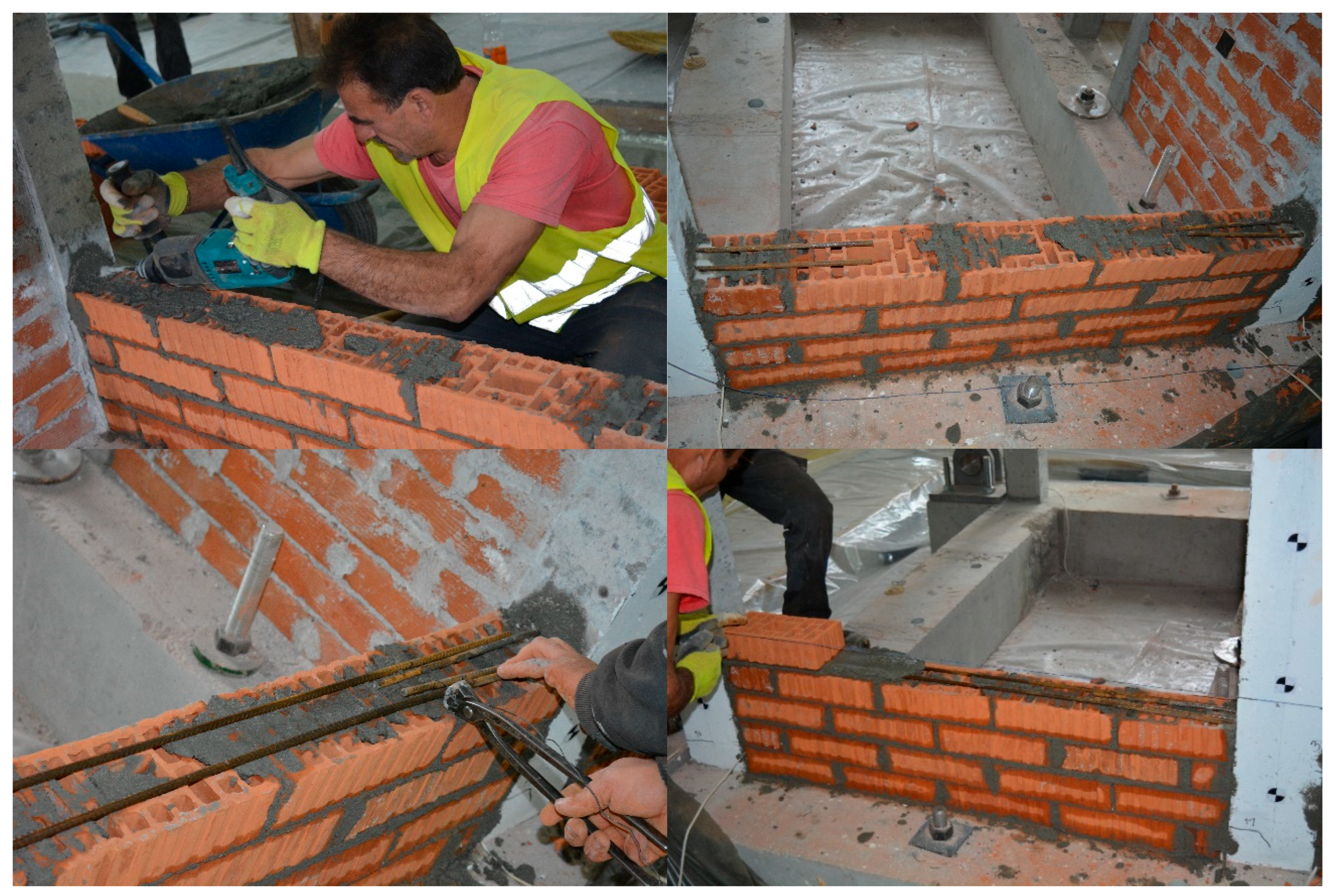
35]. Segments of the construction of the infill with the proposed connection are given in
Figure 12.
According to the design, the connection between the infill wall and the RC frame is made by two bars ∅6 mm anchored to the columns on the left and right (
Figure 12 and
Figure 13). The continuity reinforcement is placed throughout the whole length of the span. Above the reinforcement, another layer of mortar with the same depth is installed. This connection is repeated two times at each second layer of bricks starting from the top and bottom side of the wall, and one more is provided in the middle of the wall height (
Figure 14). At the bays where there were no columns, the anchorage was performed in the vertical tie. The proposed steel reinforcement is fully embedded within the mortar joints, providing substantial protection against direct exposure to humidity and temperature variations, in a similar way as regular reinforcement in reinforced-concrete elements. Therefore, it is not expecting significant impacts from environmental conditions will affect the performance of the reinforced connections over their service life.
3. Shake-Table Tests of Model with Innovative Infill Connection (Model IW-SB)
The shake-table testing of the 1:2.5 scale structural model (Model IW-SB) was conducted using a customized multi-phase testing protocol, developed to assess the seismic performance and safety of a reinforced concrete (RC) frame system with hollow-clay masonry infill walls under both linear and nonlinear dynamic excitation. The experimental program was divided into two principal phases:
(a) Dynamic Characterization Tests:
These included resonant frequency search tests performed prior to and following the seismic loading sequence. The objective was to identify the fundamental dynamic properties of the model—such as natural frequencies and modal stiffness—and to quantify stiffness degradation induced by cumulative damage (e.g., formation of micro- and macro-cracks) during testing.
(b) Seismic Response Tests:
This phase involved progressive shake-table tests using a selected earthquake ground motion record, applied in successive increments of input peak ground acceleration (PGA), ranging from 0.05 g to 1.6 g. The aim was to capture the transition from elastic behavior to inelastic response, including the onset of cracking, development of failure mechanisms, and potential collapse of the structural system under increasing seismic demand.
The specimen was constructed at a 1:2.5 geometric scale, and standard similitude principles applicable to reduced-scale dynamic testing were observed. Specifically, the Cauchy–Froude similitude law was adopted to ensure dynamic consistency between the prototype and the scale model, satisfying the relation gm/EL2 in the prototype and the model, were equal (g = gravitational acceleration, m = mass, E = elastic modulus, and L = length). To satisfy the similitude requirements, two key adaptations were implemented:
Mass addition was employed to appropriately scale the inertial effects and simulate realistic axial stress states in the vertical load-bearing members.
The ground motion time histories were compressed in accordance with the scaling law, ensuring that the dominant frequencies of the input motion matched the scaled dynamic characteristics of the model.
These adaptations are well-established in the literature on earthquake simulation of RC structures, particularly since the 1970s [
36,
37,
38,
39], and are routinely applied in experimental campaigns conducted at the IZIIS Dynamic Testing Laboratory [
40].
3.1. Instrumentation Set-Up
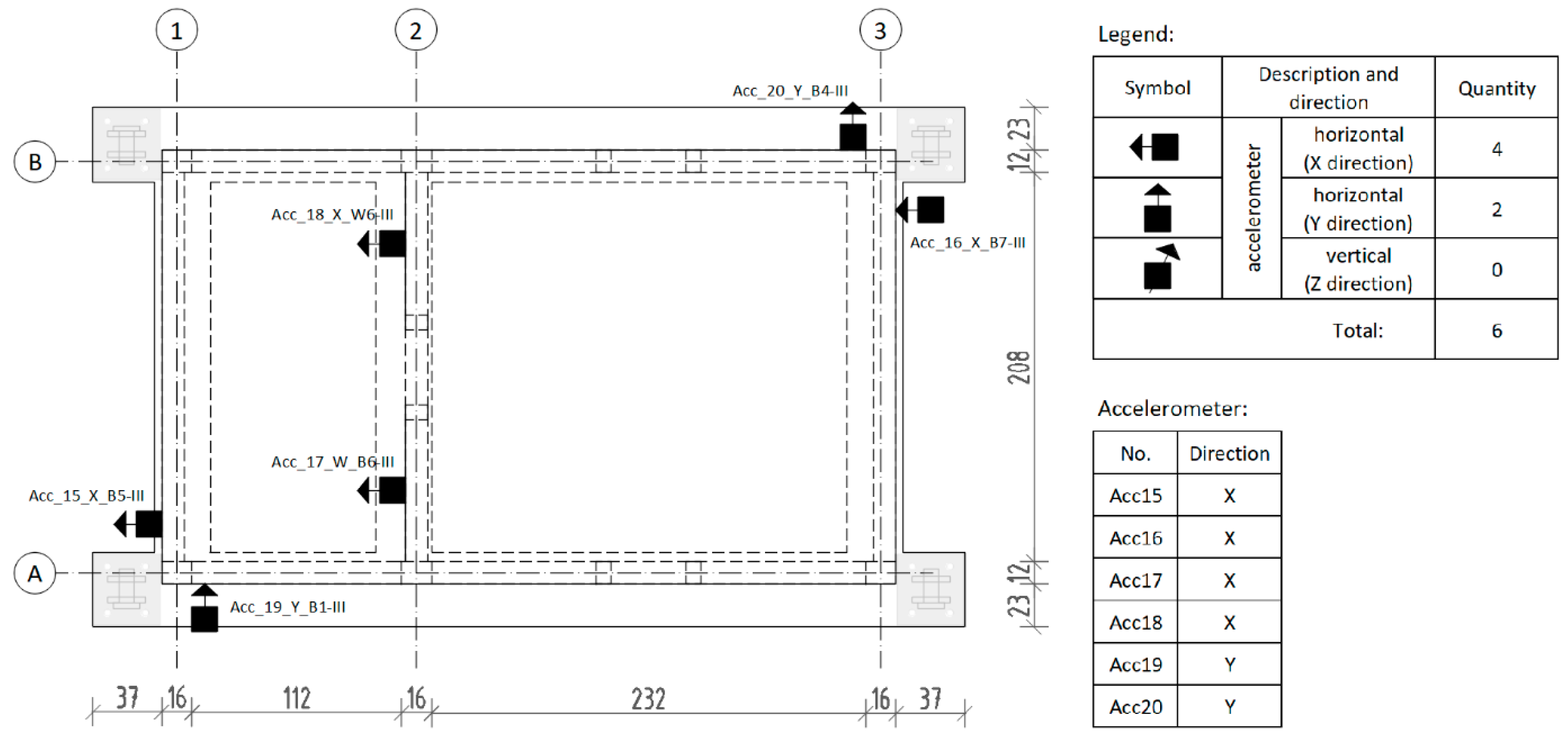
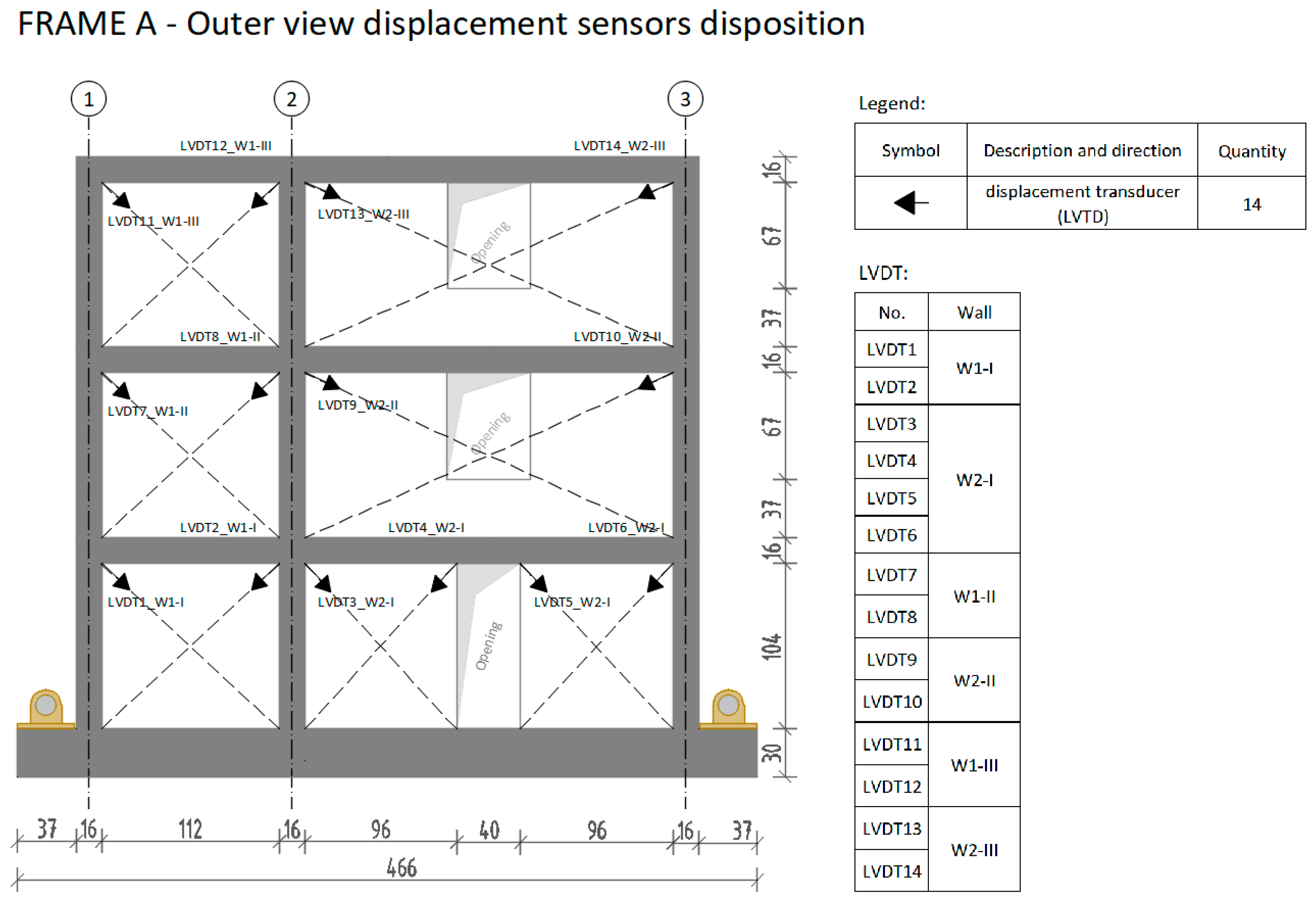
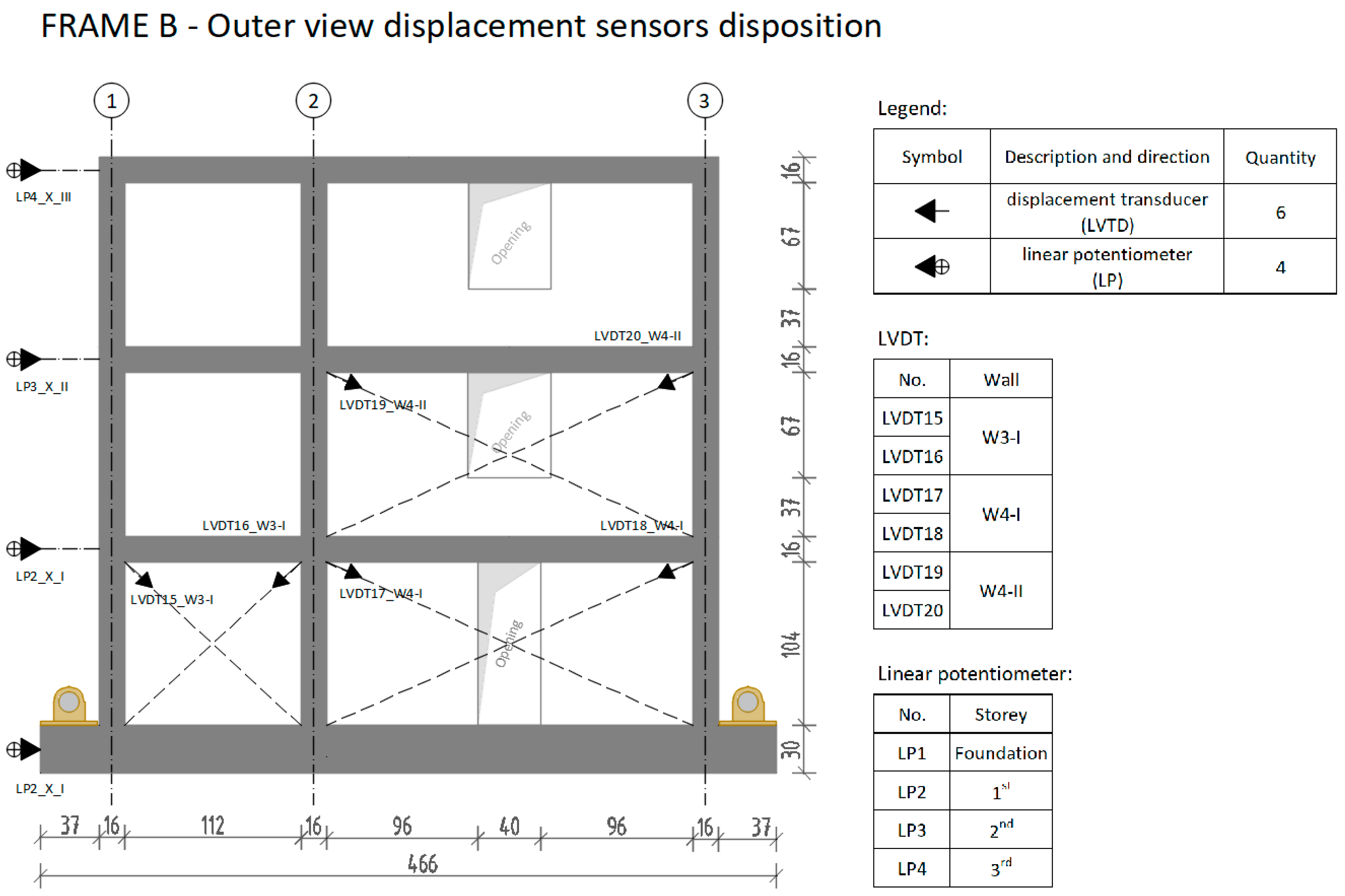
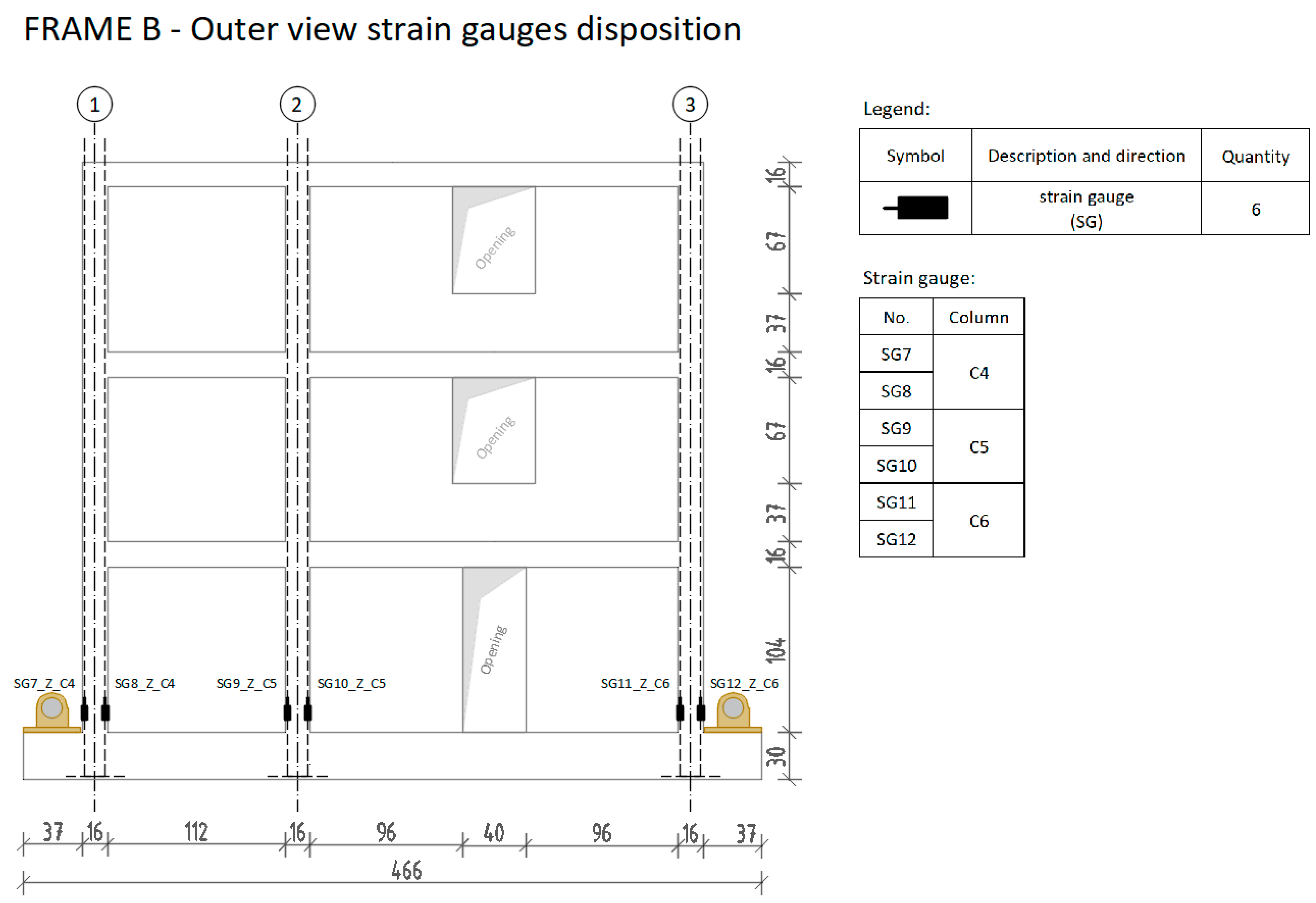
The model response was monitored by a high-speed data acquisition system consisting of 20 accelerometers (ACC), channels 1–20; 20 displacement transducers (LVDT), channels 25–44; 4 linear potentiometers (LP), channels 21–24 and 12 strain gages (SGs), channels 45–56, providing information about accelerations at different levels and points, relative displacements, deformations and strains at selected points. The complete instrumentation set-up is presented in
Figure 15,
Figure 16 and
Figure 17.
The characteristics of the transducers used for the measuring points are as follows:
- -
Linear Potentiometers (LPs):
- ∙
HSI Model 1850
- ∙
Sensitivity 0.13 mV/V/inch full range 15 inch
- -
LVDTs
- ∙
Macro Sensors Model DS750
3.2. Ground Motion for Shake-Table Tests
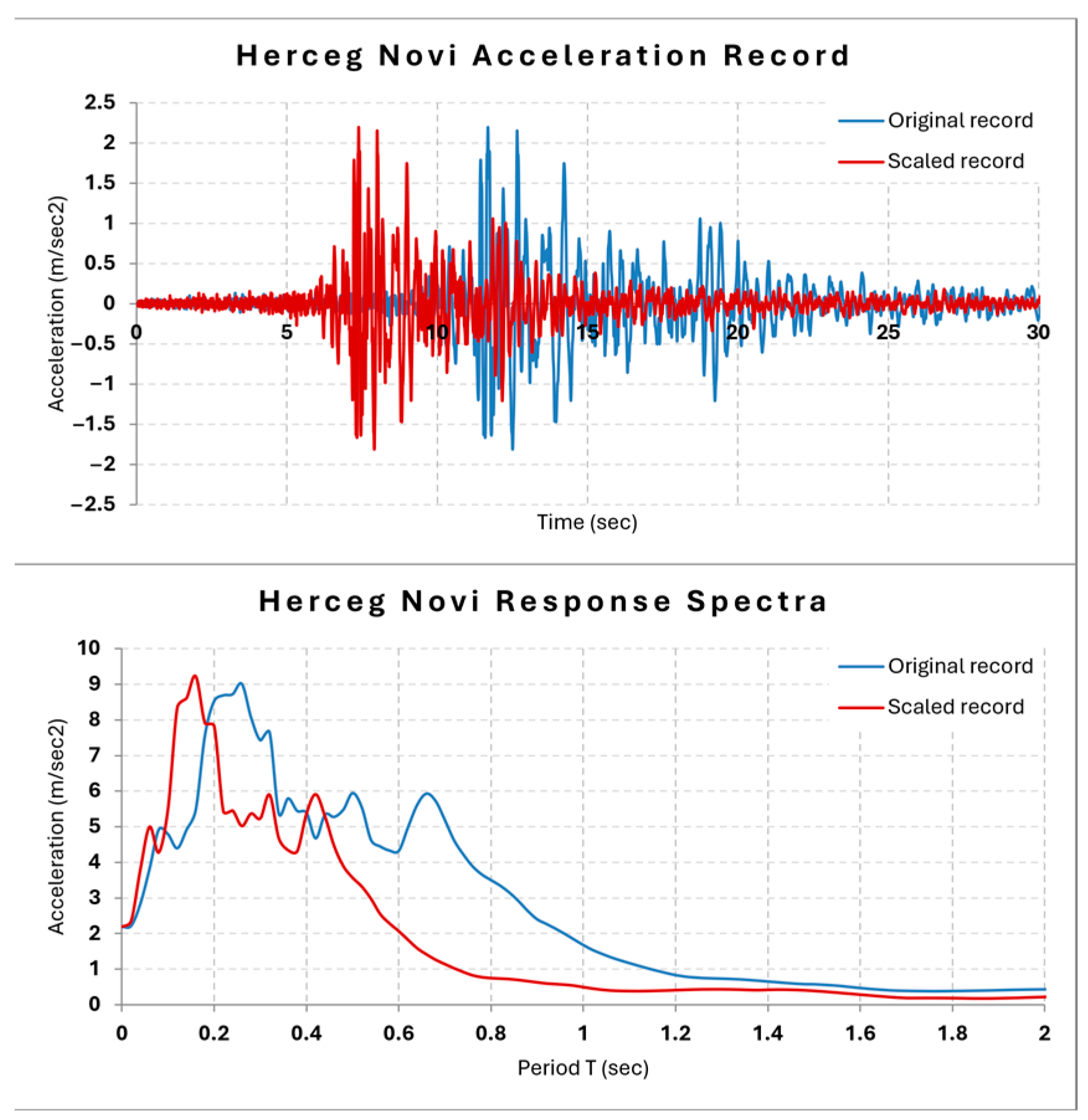
The input ground motion used for the shake-table experiments was the recorded seismic event from the Herceg-Novi station during the 15 April 1979 Montenegro earthquake (
Figure 18). This earthquake had a moment magnitude (Mw) of 6.9 and a hypocentral depth of approximately 12 km. The Herceg-Novi acceleration record was selected due to its relevance to the seismotectonic conditions of the Balkan region. Recorded in the Dinaric seismic zone—a highly active area influenced by the Adriatic-Eurasian plate interaction—it captures ground motion characteristics typical for the Balkans. The record reflects near-field effects of a shallow crustal earthquake, with appropriate PGA values and frequency content that align well with the expected seismic demands on these kinds of structures in the region. Furthermore, given the limited availability of strong-motion data from past regional events, Herceg-Novi stands out as one of the few reliable and representative records for dynamic analysis in this context.
To accommodate the 1:2.5 geometric scaling of the tested structure, the original seismic record was time-scaled by compressing its duration by a factor of 2.5, consistent with similitude requirements. Prior to scaling, the record was subjected to baseline correction to eliminate any low-frequency drifts. Subsequently, the signal was amplitude-scaled to generate input motions corresponding to different target levels of peak ground acceleration (PGA).
A total of 14 shake-table tests were conducted, of which 12 constituted seismic response tests. These tests involved incremental increases of the PGA from 0.05 g up to 1.6 g, enabling a comprehensive evaluation of the structural behavior across the full seismic intensity spectrum. This approach allowed for systematic observation of the structure’s response, capturing the transition from linear elastic behavior, through the initiation of cracking in the masonry infill walls, to the progressive development of failure mechanisms.
3.3. Selected Results Based on Measurements from Transducers
After the mounting of the model on the shake table, a random excitation test was applied in longitudinal direction of the model. This testing method is based on the concept of white noise input excitation when multi-frequency components uniformly participate in the Fourier amplitude spectrum of the input motion within the selected frequency range. Consequently, the model response contains natural frequencies as dominant in the Fourier amplitude spectra. In the presented case, a frequency range from 0.5 to 35 Hz was selected and was simulated by the shake table.
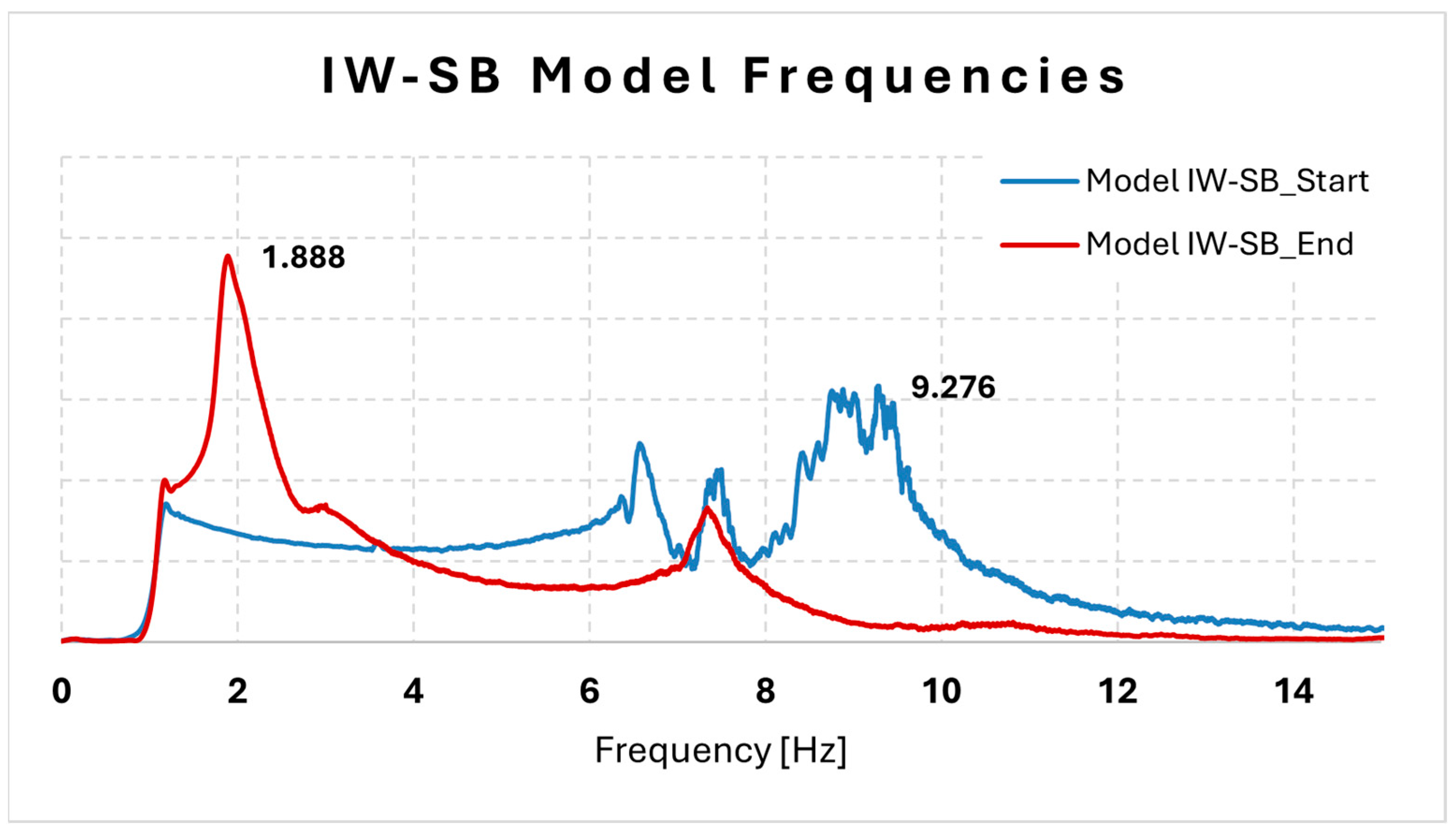
Definition of dynamic properties of Model IW-SB was the first step of the experimental testing, which enabled acquiring of important information about the stiffness (natural frequencies) of the model. Natural frequency was defined in longitudinal direction of the model by applying resonant frequency search tests. Frequencies obtained in test 01 (before the start of the seismic response tests) and in test 14 (after the finishing of the last seismic response test with PGA = 1.6 g) are presented in
Figure 19.
The analysis results indicate a significant reduction in the fundamental frequency of the structure over the course of the seismic testing. Initially, the natural frequency was measured at 9.276 Hz, which decreased to 1.888 Hz following completion of all twelve seismic response test series. Correspondingly, the fundamental period T increased from 0.108 s to 0.530 s, representing an approximate 4.91-fold increase relative to the initial period. This marked shift reflects a substantial degradation of the initial stiffness, primarily attributed to damage accumulation in the masonry infill panels.
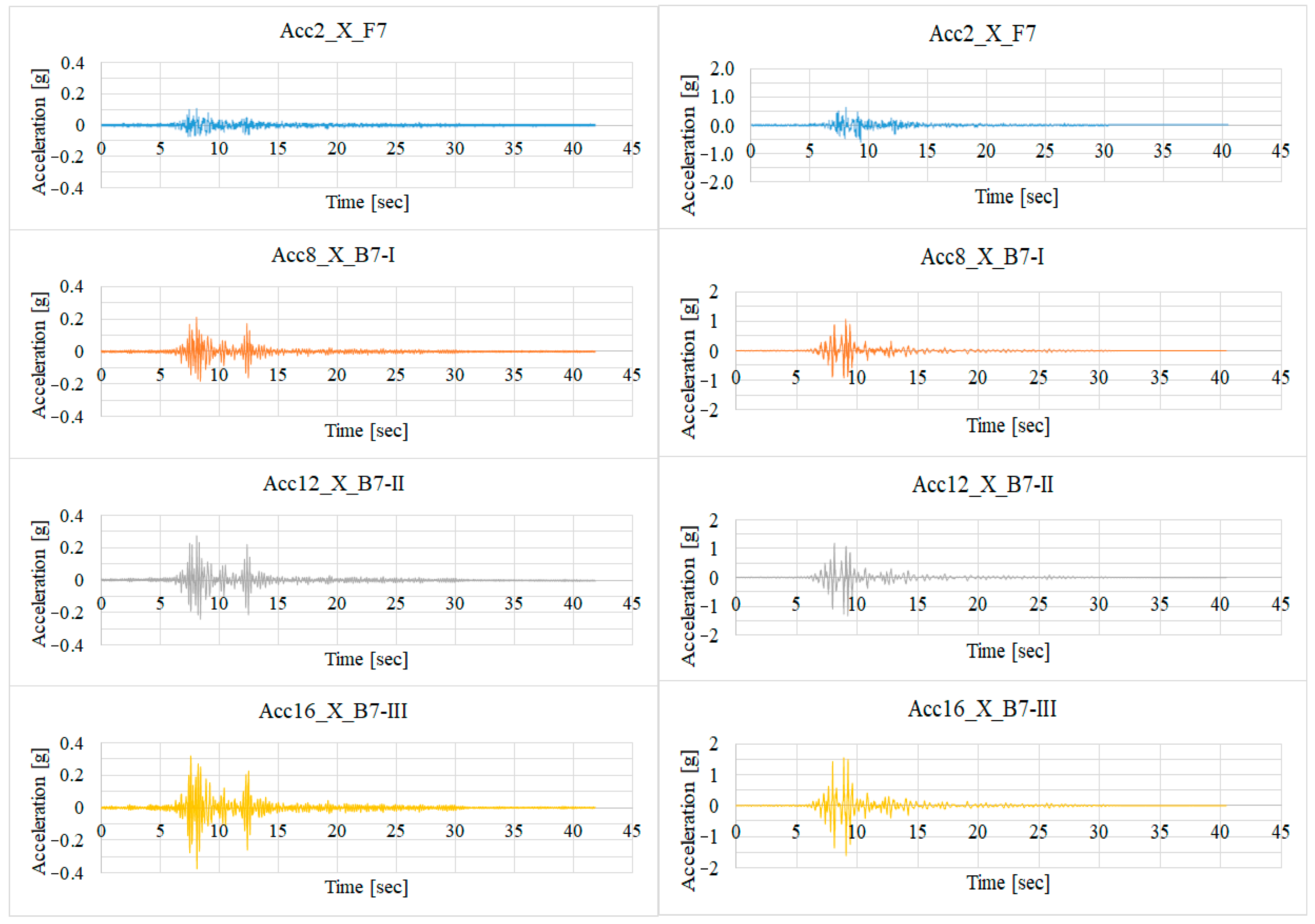
Acceleration and displacement data, recorded via transducers (
Figure 20 and
Figure 21) and complemented by strain gauge measurements, are presented for four selected peak ground accelerations (PGAs): 0.1 g (low amplitude), 0.6 g (moderate amplitude), and 1.2 g and 1.6 g (high amplitudes). Raw data were processed using a double band-pass filter with cutoff frequencies set at 0.3 Hz (low) and 44 Hz (high) to remove noise and drift effects.
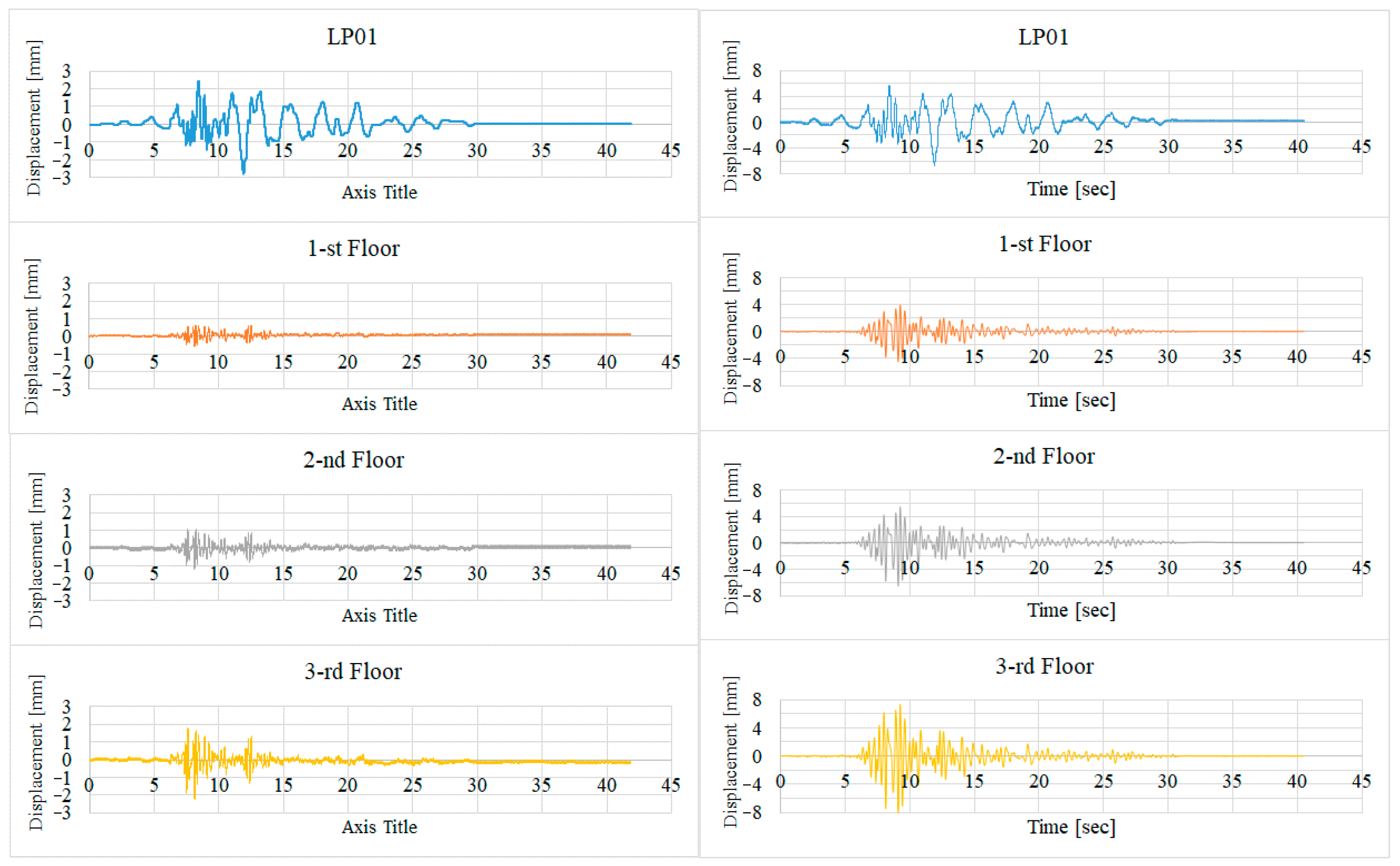
Prior to detailed analysis, displacement time histories from the linear potentiometers (LP1–LP4) were cross-validated against displacement curves derived from double integration of acceleration records. The close correspondence between these datasets confirmed the reliability of the potentiometer measurements, which were subsequently utilized for all further analyses.
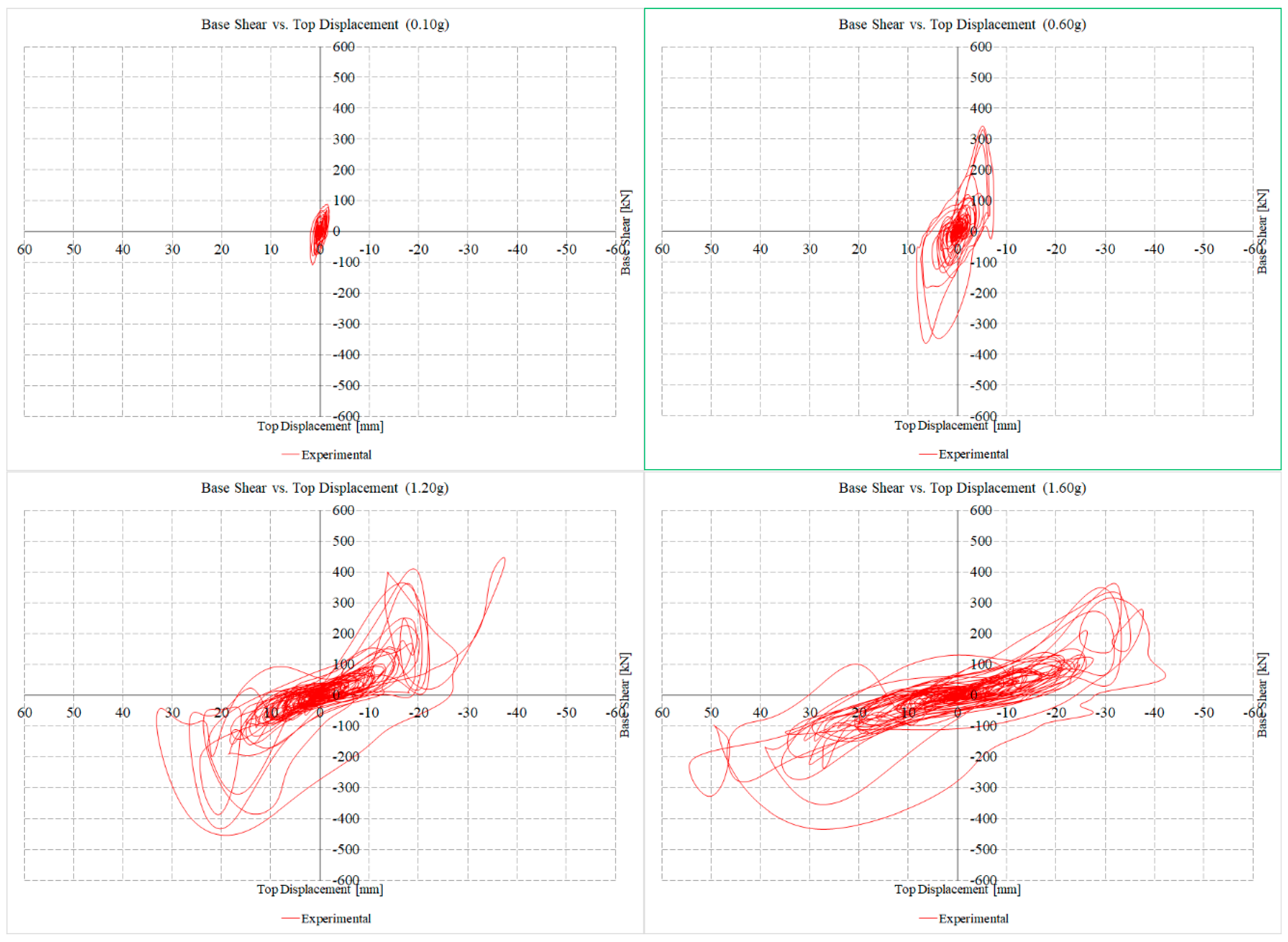
Table 2 summarizes the maximum top displacements and inter-story drifts measured at the selected excitation levels. The maximum displacement at the roof level was approximately 2 mm for 0.1 g, 7 mm for 0.6 g, 38 mm for 1.2 g, and 52 mm for 1.6 g, indicating progressive nonlinear deformation with increasing seismic intensity.
Additionally, base shear versus top displacement hysteresis loops were developed (
Figure 22) to characterize the global structural response. The displacement time history recorded by transducer LP-01, located at the foundation level, served as the reference point for calculating relative floor displacements using measurements from other channels (LP-02 through LP-04).
- -
Base shear vs. top displacement
In order to present the seismic performance of Model IW-SB during the shake-table tests, base shear vs. top displacement graphs are plotted in
Figure 17. The base shear force was calculated from the accelerometer measurement at the ground level multiplied by the model mass. The graphs clearly show the seismic performance of the structure, the degradation of stiffness, and the nonlinear behavior of the structure.
3.4. Visual Observations of Damage to the Infill
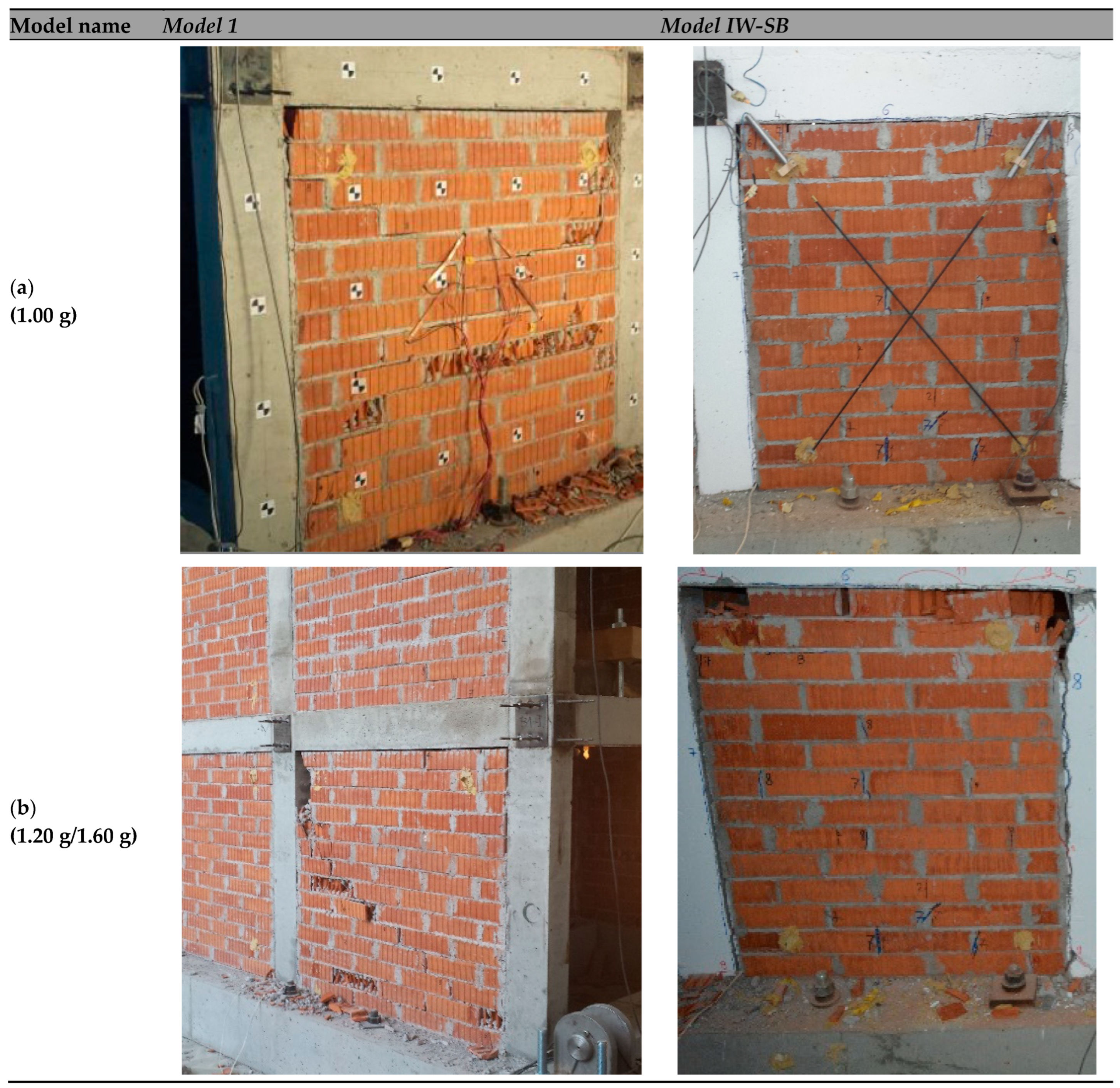
Presented further are the photos of damage to the infill during the shake-table tests in respect to the referent Model 1 (
Figure 23). The observed damage sequence during testing, including the timing and location of initial cracking, and development of localized shear cracks under defined level of excitation is presented further. Under an input acceleration of less than 0.4 g, the structure experienced negligible-to-slight damage to the first story walls (based on definitions in (ATC, 1998, [
41]). At the level of 0.4 g, in both test series, cracks began to form around the perimeter of the infill walls with some crushing at the corners. At 0.8 g, in Model 1, the first and the second story infill walls began to develop inclined cracks at isolated locations. These cracks were formed in both directions. At the end of testing of Model 1 (PGA = 1.2 g), the infill wall adjacent to the door opening collapsed and significant diagonal cracks occurred in the infill panels (
Figure 23, left).
In contrast, the infill damage at the end of testing of Model IW-SB was concentrated only at the connections of the panel with the RC frame. The infill panels in Model IW-SB were engaged more effectively in resisting the lateral demands and kept their integrity until the last level of excitation of 1.6 g. This observation contributed to the statement that, with the proposed connection, the seismic capacity and in-plane and out-of-plane stability of the infill were significantly improved (
Figure 23, right).
This failure mechanism demonstrated that full length steel bars strengthened the infill panel and improved its integrity. The infill panel was kept stable because of the six layers of full-length connection bars anchored to the columns. The full-length connection bars did improve the in-plane stability of the infill panel under earthquake excitation; however, the deployed steel bars could also change the crack propagation in the infill panel. Under PGA = 1.6 g, flexural cracks developed in the plastic hinge regions of the columns, and the maximum first story drift ratio reached 2.89%. It should be pointed out that a reliable connection detailing method could provide a stable out-of-plane capacity of the infill panels. The infilled frame exhibited a favorable seismic performance with no observed damage to the RC frame members. It should also be noted that during the entire test series, including the highest excitation levels, no visible slippage of the steel bars was observed. The bars remained embedded and fully engaged with the surrounding masonry. This observation is supported by the damage photographs (e.g.,
Figure 23), where no signs of movement or disengagement at the interface zones are visible.
For Model 1 (as a referent model for comparison) sine sweep tests are performed at the beginning and after the test with earthquake excitation of 0.60 g. The values of the frequency of the model were 8.785 Hz and 3.047 Hz respectively, or the frequency is decreased for 2.90 times. For this model, sine sweep test are not performed after the last series of seismic test of 1.20 g earthquake excitation. However, since Model 1 had already shown visible damage at that lower intensity and IW-SB remained undamaged until 1.0 g, the observed difference in frequencies shown in
Table 3 cannot be interpreted as greater stiffness degradation in IW-SB. Rather, it reflects that the IW-SB model endured higher seismic demand before reaching comparable damage levels.
It can be seen that the frequency of the Model IW-SB, at the start of the testing, is around 5.6% bigger than for Model 1 (
Figure 24,
Table 3), which is expected, as both models have the same geometry and mass, and the only difference lies in the frame–infill connection. The IW-SB reinforcement does not contribute additional stiffness in the undamaged state.
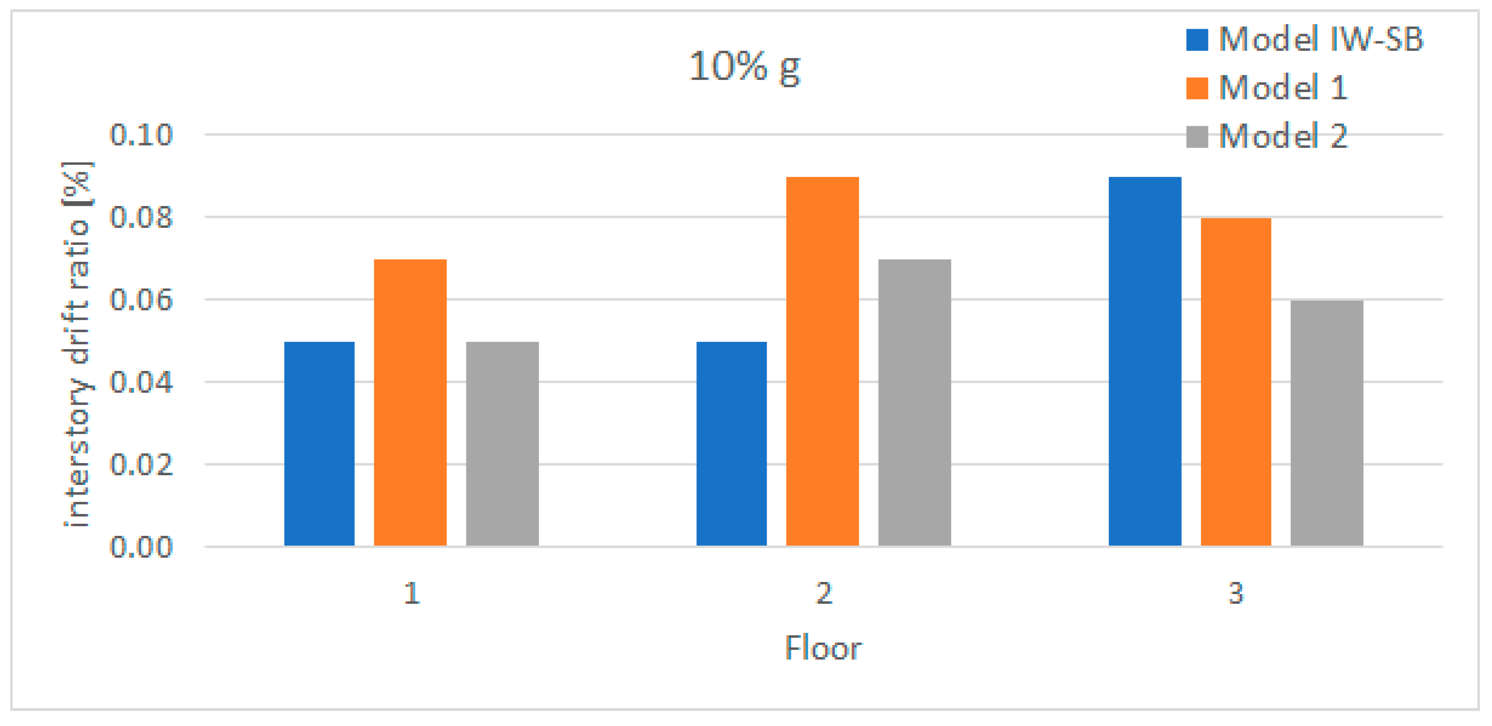
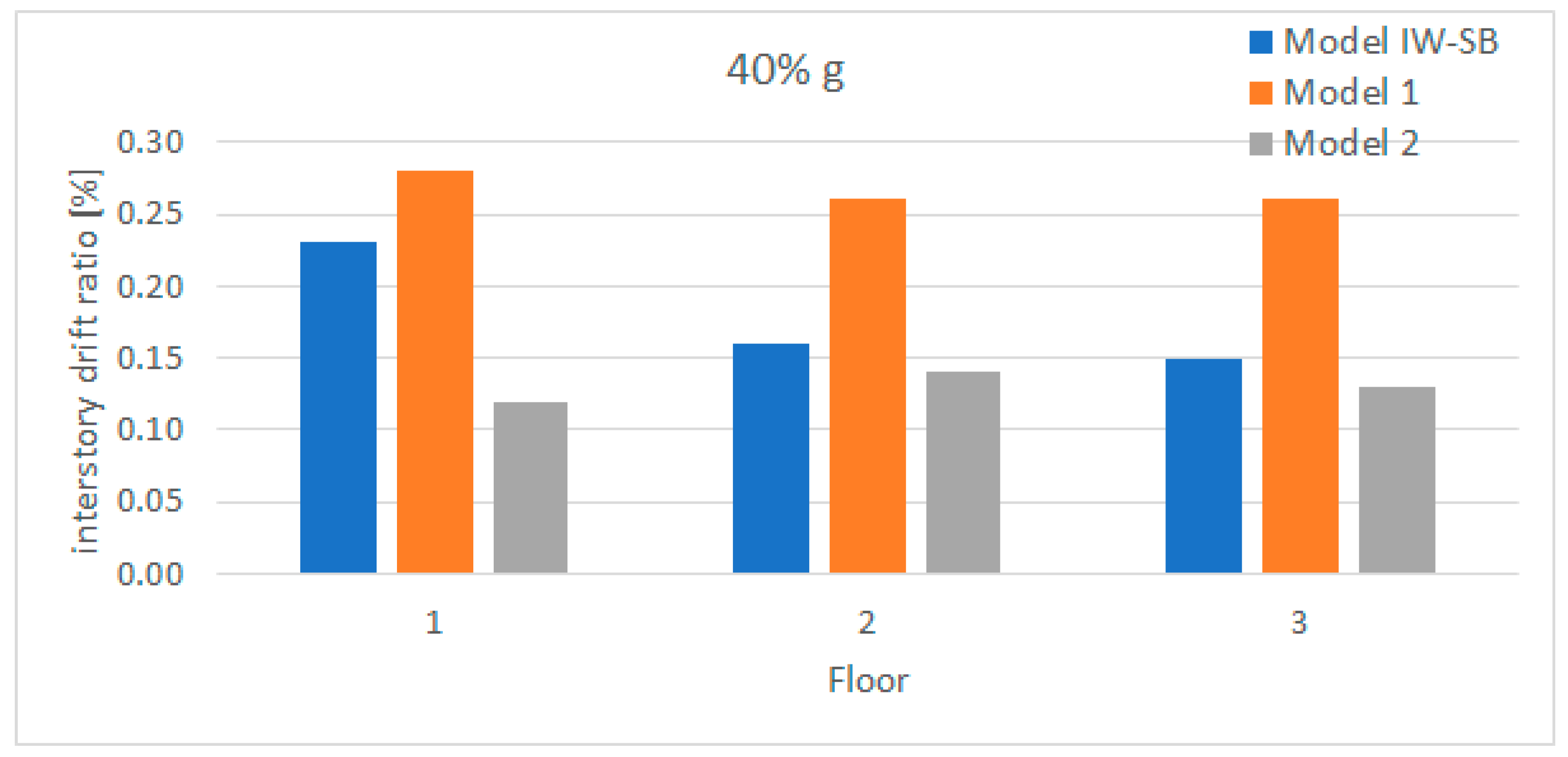
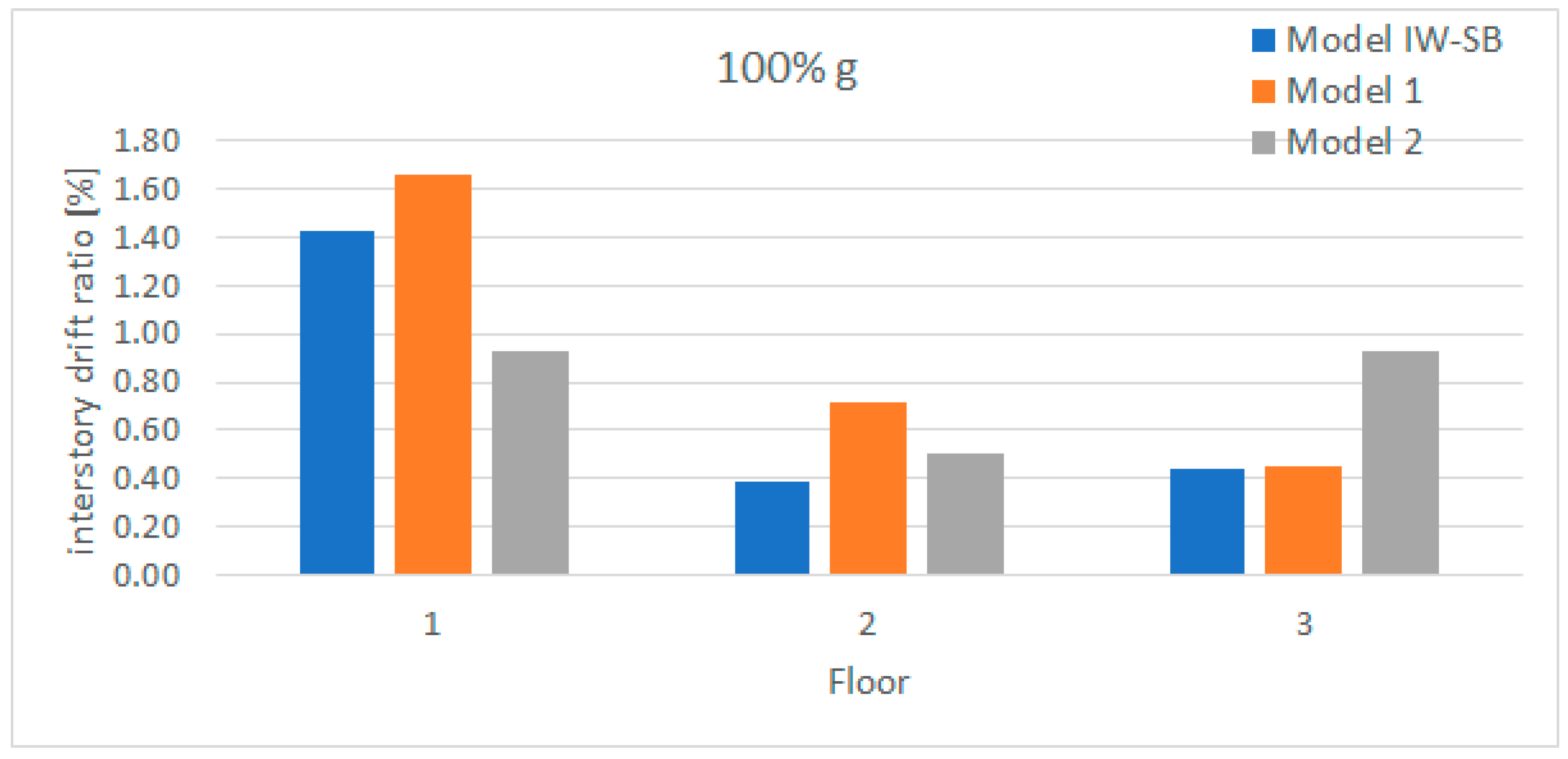
3.5. Comparison of Inter-Story Drift Ratio with Referent Models
The inter-story drift ratio was calculated for each level of seismic excitation based on the LP measurements from the tests. These drifts were compared with the results obtained for Model 1 and Model 2, published by [
34]. It can be observed that the inter-story drifts in Model IW-SB are lower than those of Model 1, which leads to the conclusion that the proposed method for connection between the infill and the RC frame significantly improves the seismic performance of the overall structure. Regarding Model 2, which is built with a solid clay infill, under lower and intermediate amplitude excitation, Model IW-SB exhibits higher values of drifts, which is expected, having in mind the higher stiffness of the solid clay masonry in general. Yet, under the highest amplitude excitation, Model 2, in some cases, goes beyond Model IW-SB with the inter-story drifts, which means that the new proposed Model IW-SB can sustain a very high level of excitation without significant damage and large plastic deformation.
Figure 25,
Figure 26,
Figure 27 and
Figure 28 show the compared values of inter-story drifts under 10% g, 40% g, 100% g, and 120% g excitation.
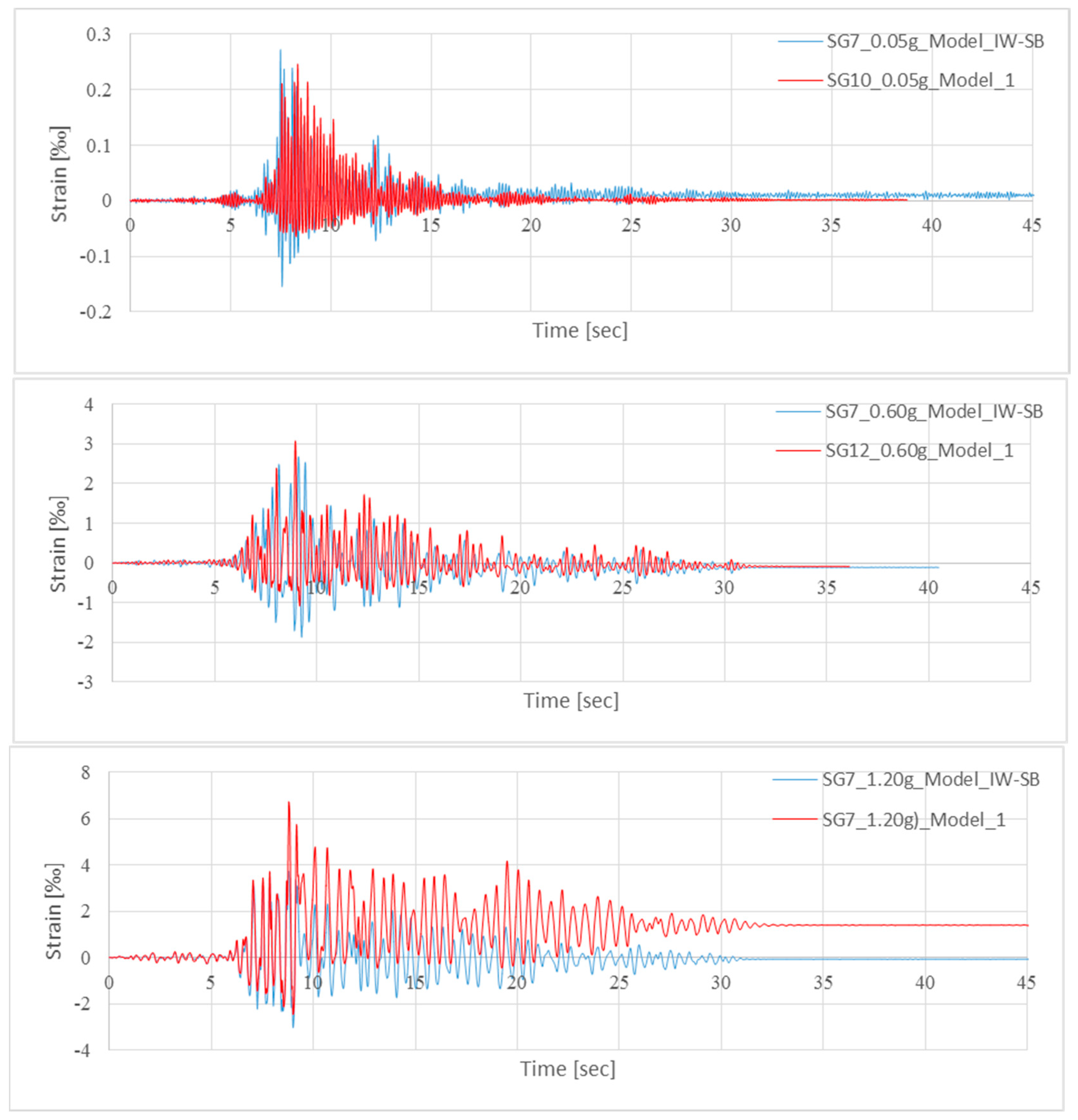
- -
Comparison of strain in the reinforcement of the columns
Results from comparison of the strain measurements with the referent Model 1 show that maximum values measured for strain for Model 1 are higher than the values measured for Model IW-SB, (
Figure 29). This statement also contributes to the fact of better seismic performance of Model IW-SB.
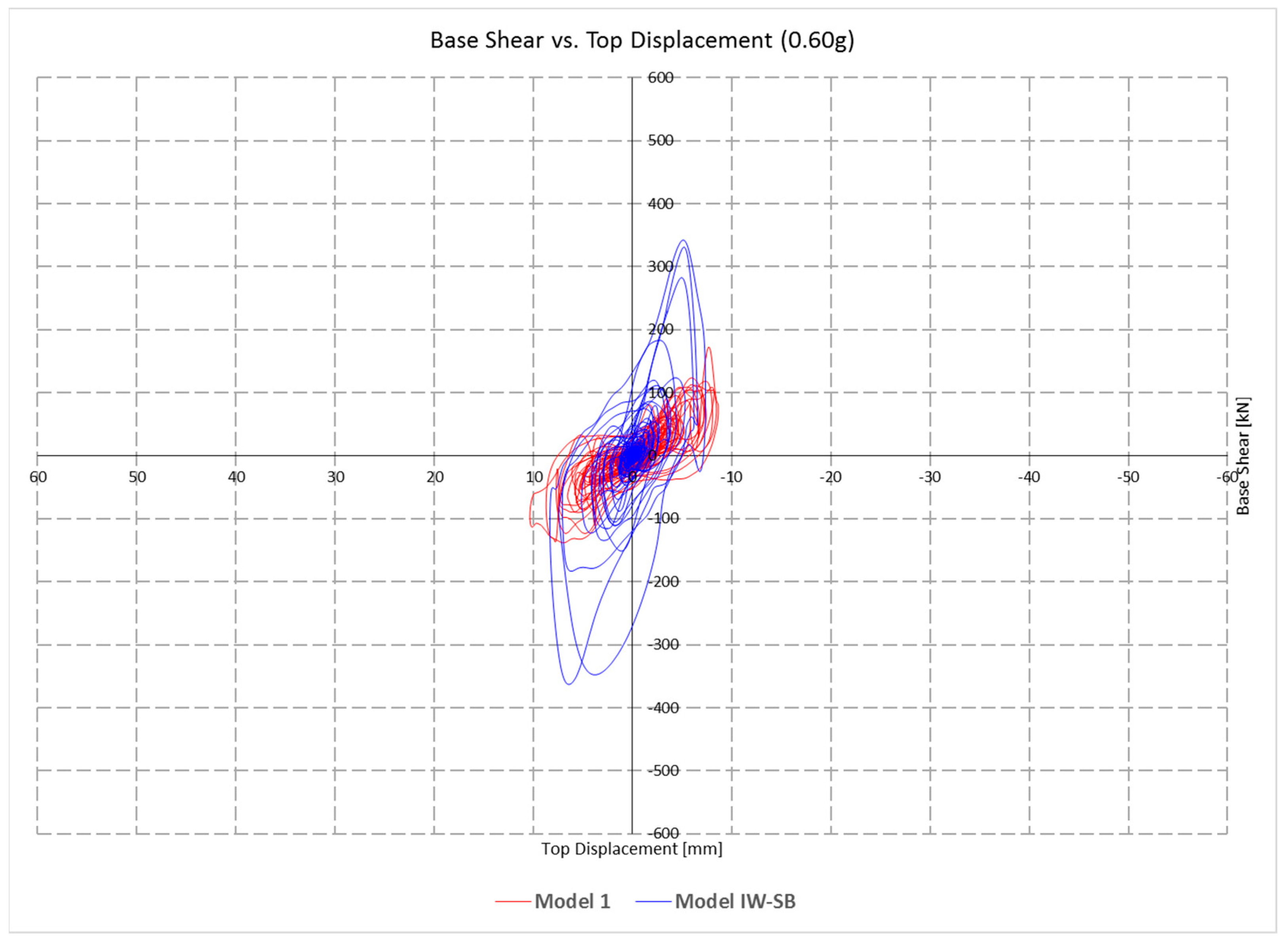
- -
Comparison of base shear—top displacement diagrams
Base shear vs. top displacement graphs are compared to the referent Model 1 and presented on the following graphs (
Figure 30,
Figure 31,
Figure 32 and
Figure 33). From the results it can be observed that for higher excitation the Model IW-SB is slightly stiffer than Model 1 and thus has better seismic performance in the nonlinear zone of structural behavior.
5. Conclusions
The innovative connection detailing method, named Model IW-SB, proposed in this research was proved to be an effective and favorable solution in high seismicity areas. Under low seismic excitation, minor cracks could be observed in the infill panels and the frame members tended to behave in the expected mode according to the structural analysis. Under medium and high seismic excitation, the infill walls interacted with the bounding frame and provided structural redundancy to resist horizontal actions, and because of steel wire connections deployed in the mortar layers, satisfying in-plane stability and integrity of the infill panels could be achieved until the ultimate level of excitation.
A general conclusion can be drawn that based on the comparative analysis between Model IW-SB and the referent Models 1 and 2, the Model IW-SB has better capacity for strength and deformation, especially for high seismic excitation.
From the extensive experimental investigation performed in this study, it can be concluded that the proposed innovative connection detailing method can effectively mitigate undesirable damage to masonry infilled RC frame structures. The proposed technical solution consists of connection of the infill panel with bounding columns with steel wire connections, which are deployed in mortar layers and anchored to columns. The proposed simple connection is practical, cheap, and easy to implement without any specific technology, which is very important for developing countries in seismic regions such as N. Macedonia. Globally, the structural stability and integrity, the displacement ductility and the energy dissipation capacity of the masonry infilled RC frame are substantially improved. In view of the large number of masonry-infilled frame buildings in N. Macedonia and the Balkan region, the presented research is expected to provide useful guidance for seismic assessment and design of safer frame structures. Unlike traditional bed-joint or surface-mounted techniques, the IW-SB system offers a simplified internal anchorage approach that responds to observed stress demands while minimizing material and installation complexity.
While the proposed method is primarily designed to offer a low-cost and easily implementable solution suitable for developing countries, it also has potential benefits in reducing overall construction costs in modern high-rise projects by serving as an effective alternative or complementary technique to more expensive methods, such as rubber bearings etc.
Real-world applications would further support the practical relevance of the proposed method. While this study is primarily experimental, the reinforcement technique was developed in close collaboration with local construction practitioners, using readily available materials and tools. Future work will focus on field implementation and validation to further demonstrate the method’s low cost and ease of use in practice. While the current study focuses on structural integrity and ultimate capacity under a single strong event, it is also important to test the method on potential impact on serviceability after multiple seismic events. It should be specifically noted that while some reduction in stiffness and minor cracking may occur, the proposed reinforcement aims to limit damage progression, suggesting a positive effect on maintaining serviceability. However, further cyclic or repeated loading tests would be beneficial to fully evaluate long-term performance in future studies.
Even though the IW-SB method was primarily developed for new construction, it may also be adapted for retrofitting existing RC frame buildings. In such applications, particular attention must be given to the local stress concentrations introduced at the anchorage zones within the existing columns. A prior structural assessment is necessary to verify whether the column cross-sections and detailing are sufficient to accommodate the added forces, or whether local strengthening is needed before implementation.
Although the IW-SB system was evaluated through a sequence of 12 scaled earthquake simulations of increasing intensity—providing valuable insight into cumulative damage effects—the campaign was nonetheless confined to 1:2.5 scale specimens. Full-scale validation remains necessary to confirm the transferability of the results to real-world structures, including the long-term behavior of the dowel-lap anchorage detail. Moreover, while the test frame did incorporate door- and window-sized openings (tied vertically at the jambs), only one opening configuration was examined. Future work should therefore explore a broader range of opening sizes, positions, and percentages, as well as frames with larger bay widths or irregular geometries. Developing simplified analytical/strut-and-tie models for everyday design use, and investigating possible enhancements through alternative tie materials or hybrid dissipative details, would further generalize the method’s applicability.


 ,
, 


