Article

Point-Kernel Code Development for Gamma-Ray Shielding Applications

by
Mario Matijević
1,*,
Krešimir Trontl
1,
Siniša Šadek
2 and
Paulina Družijanić
2
1
Department of Applied Physics, University of Zagreb Faculty of Electrical Engineering and Computing, Unska 3, 10000 Zagreb, Croatia
2
Department of Energy and Power Systems, University of Zagreb Faculty of Electrical Engineering and Computing, Unska 3, 10000 Zagreb, Croatia
*
Author to whom correspondence should be addressed.
Appl. Sci. 2025, 15(14), 7795; https://doi.org/10.3390/app15147795
Submission received: 29 May 2025 / Revised: 5 July 2025 / Accepted: 9 July 2025 / Published: 11 July 2025

Abstract

The point-kernel (PK) technique has a long history in applied radiation shielding, originating from the early days of digital computers. The PK technique applied to gamma-ray attenuation is one of many successful applications, based on the linear superposition principle applied to distributed radiation sources. Mathematically speaking, the distributed source will produce a detector response equivalent to the numerical integration of the radiation received from an equivalent number of point sources. In this treatment, there is no interference between individual point sources, while inherent limitations of the PK method are its inability to simulate gamma scattering in shields and the usage of simple boundary conditions. The PK method generally works for gamma-ray shielding with corrective B-factor for scattering and only specifically for fast neutron attenuation in a hydrogenous medium with the definition of cross section removal. This paper presents theoretical and programming aspects of the PK program developed for a distributed source of photons (line, disc, plane, sphere, slab volume, etc.) and slab shields. The derived flux solutions go beyond classical textbooks as they include the analytical integration of Taylor B-factor, obtaining a closed form readily suitable for programming. The specific computational modules are unified with a graphical user interface (GUI), assisting users with input/output data and visualization, developed for the fast radiological characterization of simple shielding problems. Numerical results of the selected PK test cases are presented and verified with the CADIS hybrid shielding methodology of the MAVRIC/SCALE6.1.3 code package from the ORNL.

1. Introduction

The point-kernel technique (PK) applied to gamma radiation shielding is a very developed method, originating from the early days of nuclear reactors, nuclear power expansion and digital computers [1]. The Oak Ridge National Laboratory (ORNL) in USA was and still is one of the leading world facilities conducting pioneering research on computational and experimental aspects of radiation shielding, such as criteria and procedures for shield design, neutron-gamma attenuation, pool-type reactors, fast neutron removal, radiation streaming (albedos, ducts and voids), scattering from various structures, shield heating and weight optimization, shielding materials, analytical (ray tracing) and Monte Carlo (MC) methods, buildup B-factor concept, etc. The PK method for gamma radiation shielding is one of many successful methods developed over time, such as the Goldstein moments method, Spinney removal diffusion, corrective B-factor, etc. The basis of PK method is the linear superposition principle applied to distributed radiation sources, which are shielded with relatively simple shields, with point detector response being the objective of the calculation [2]. In a mathematical sense, the distributed source will produce a detector response equivalent to numerical integration of the radiation received from an equivalent number of point sources. In such a treatment, there is no interference between individual point sources, while inherent limitations of the PK method are inability to properly account for gamma scattering in shield and application of simple boundary conditions. Besides these restrictions, the PK method generally works for gamma-ray shielding problems (with inclusion of B-factor concept) and only specifically for fast neutron attenuation in hydrogenous medium (with definition of removal cross section) [1,2].
The common exposure B-factors used in most computer programs are for point gamma source in infinite medium and have a remarkable durability since they were introduced by Goldstein in the late 1950s [3]. Tables of B-factors are readily available for gamma-ray energy and shield thickness (in mean free paths) for different materials and should be differentiated for point source and planar source. When performing the integration of distributed sources, it is often necessary to express B-factors in analytical form, and in this paper, we have used and compared several different forms. An excellent overview and historical evolution of analytical B-factor forms was carried out by Trubey [4], while supplementary data on B-factor parameters can be found in most appendices of typical radiation shielding handbooks [1].
Relatively recent publications and ongoing research in connection with B-factor concept in PK gamma-ray shielding can be seen in a variety of fields. The common intention of these trends is to achieve a better predictability of B-factors for complex composite shields, more flexible energy spectra, the integration of data-driven machine learning (ML) models trained on referent MC datasets, localized MC corrections for particle streaming, curvature corrections, multiphysics coupling, and so on. These efforts should well surpass traditional PK limitations of tabulated B-factors that have been used successfully for many decades in the radiation shielding community.
Kang et al. [5] developed a user-friendly PK program to estimate dose rates from 15 fixed geometry sources, 98 shield materials and compounds, several B-factor forms, 18 organ models from various exposure directions, internal decay library for 550 nuclides, and visualization options. Trontl et al. [6] showed how a support vector regression model, coming from a statistical learning theory, can be used for estimation of gamma-ray B-factors in multilayered shields. Subbaiah and Sarangapani [7] developed a stand-alone PK code similar to a well-known QADCGGP code, with geometry improvements in connection to fast reactors and radioactive plum release from a stack: multiple source shapes and energy distributions, hexagonal cylinder as a shield body, arbitrary source orientation, visualization of 3D objects, etc. Zeb and Wasim [8] developed an open-source program for estimating the thickness and height of depleted uranium shield for storing the gamma-ray point sources commonly used in nuclear industry and medicine, such as 60Co, 137Cs, 131I and 99Mo. Yang et al. [9] implemented a voxelization algorithm using the PK method for modeling arbitrary shape 3D solids. The method is suitable for the radiological assessment of arbitrary shape components produced by cutting during decommissioning phase. Li et al. [10] developed a 3D model-based gamma-ray shielding package using a virtual reality platform for radiation dose assessment in nuclear safety and better usage of the PK method in interactive virtual simulations. Kumar and Mammen [11] developed 3D geometry and mesh modeling based on open-source finite element software with additional features such as irregular source shapes, distributed gamma spectrum, modeling multilayered shields, and exporting results for advanced visualization. Li et al. [12] integrated deep neutral network for calculating the B-factor of multilayered shields. Important physical parameters of photon transport were trained using a neural network for B-factor prediction, resulting in a quick and accurate method for 3D radiation field calculation with broad application prospects.
Xu et al. [13] extended previous work to a GPU-based computing framework for advancing the computing power of virtual engine and proposed a novel voxelization algorithm of volumetric radioactive source. Sun et al. [14] introduced NPTS-PK code supporting various B-factor calculations, acceleration of ray tracing, adaptive source geometry discretization and ability to handle a large-scale grid counting. Chen et al. [15] developed a new 3D PK gamma shielding tool which proved to be proficient in calculating multi-layer buildup factors.
The concept of buildup factors can be, at least in general, applied to both gamma rays and neutrons [16,17], but for practical purposes it is mainly used for gamma-ray attenuation calculation as complex neutron interactions are more suitable for the MC method. The advance in machine learning and AI algorithms also gives an incentive to integrate such novelties inside the classical point-kernel paradigm [18].
It is evident how the “historical” PK method is used even today for integration with novel methods and technologies, boosting its potential for various applications. This paper presents one such effort, giving the theoretical and programming aspects of the analytical gamma flux solution on a point detector from several distributed sources of photons (line, disc, plane, sphere, volume slab, etc.) penetrating a slab shield. The used analytical B-factor forms are simple enough to allow the integration and derivation of closed-form solutions for gamma flux. These specific computational modules are currently being incorporated into a graphical user interface (GUI) with visualization options, developed for fast radiological characterization of simple shielding geometries. This will provide the user with a valuable supporting information in initial stage of shield design, often requiring many fast calculations for “filtering” out suitable composition of materials and/or geometry arrangement. After that, a more demanding particle transport simulation using production codes can provide the user with a detailed physical solution, capturing many microscopic phenomena which are out of the reach for the PK method. For that purpose, we have verified our selected PK shielding test cases with a referent MAVRIC MC solution [19]. This effort is an ongoing process with future plans for PK program expansion and implementation of machine learning and AI algorithms.
The rest of the paper is organized as follows. Chapter 2 gives a formal PK definition for a point gamma source with the introduction of the exponential attenuation kernel and B-factor. Chapter 3 presents the analytical solution of gamma-ray flux in a slab shield for several source distributions (disc, plane, line, sphere, volume slab). The programming details and overview of the PK program are given in Chapter 4 using a test case of gamma disc, slab shield, and point detector. The comparison of PK and referent MC results are presented in Chapter 5 for normalized gamma sources of isotropic disc, sphere and slab using sensitivity study on slab shield thickness. Chapter 6 presents a discussion on the obtained results and PK program functionalities with future work plans. Conclusions are given in Chapter 7, while the supportive CADIS methodology [19] used in MC simulations is briefly presented in the Appendix A. The list of references is given at the end of the paper.

2. The Point-Kernel Approach in Radiation Shielding

The PK method has a long history in radiation shielding problems and is mostly used for gamma-ray simulations, since complexities of the neutron cross sections demand alternative computational approaches such as MC or deterministic method of discrete ordinates (SN) [20]. The gamma source of arbitrary shape (linear, planar or volumetric) can be represented by an equivalent number of point sources, so total point detector response can be found as a summation, i.e., numerical integration of radiation received from those point sources. The exponential attenuation kernel is used for such point source, and depends on source–detector distance R, gamma-ray energy Eγ and shielding material properties (mass attenuation coefficient µ/ρ) [1,2]. For an isotropic point gamma emitter of Sp intensity (phot/s) located in a uniform medium with linear attenuation coefficient μ (cm−1), the uncollided gamma flux at a distance R from the source is given as
ϕ ( R ) = S p 4 π R 2 exp ( μ R ) .
The shield thickness is given as μR, which is equal to the number of gamma-ray mean free paths inside the shield. The PK attenuation kernel is defined as the point detector response from a point source emitting one particle per second, so it has the following form:
G ( R ) = exp ( μ R ) 4 π R 2 .
However, every practical shield is thick enough to produce multiple scatterings of gamma rays, increasing their probability of reaching the detector. The flux correction is introduced by a multiplicative buildup factor B > 1, so the corresponding kernel is given as
G ( R ) = exp ( μ R ) B ( μ R , E γ ) 4 π R 2 .
This corrective B-factor is crucial in shielding calculations, and tables and curves of B-factors are readily available as functions of gamma-ray energy and shield thickness. To permit an analytical integration of general, distributed gamma source, B-factors are typically expressed in parametric form with tables of fitting coefficients that depend on shielding material and gamma-ray energy. In our work, we used a well-known Taylor form given as
B ( μ R , E γ ) = A exp ( α 1 μ R ) + ( 1 A ) exp ( α 2 μ R ) ,
where A, α1 and α2 are readily available from the classic literature on the gamma radiation shielding [1,2]. The total or buildup flux would be calculated by merely multiplying Equation (1) using the Taylor or alternatively Berger form of the B-factor given as [1,2]
B ( μ R ) = 1 + μ R ( C e D μ R ) ,
where tabulated parameters C and D again depend on the gamma-ray energy and shielding material. The first term represents the uncollided, and the second term the scattering contribution. These forms balance accuracy with simplicity to permit analytical integration, while more complicated forms, such as the modified geometric progression of Y. Harima [21], will be fully implemented in future program versions. A comprehensive review on the current status of B-factors calculations and applications can be found in [22].

3. Gamma Flux Solution for Simple Source Geometries

This section gives an overview of the most common source geometries that are encountered in practical shielding and are implemented in our PK code. These source distributions correspond to a real-life source such as a fuel rod, spherical reactor core, general surface source or slab source of radioactive material. The variations in these geometries can be found in a classical reference by Wood [23] and implement similar analytical steps. The derived flux solutions go beyond classical textbooks as they include analytical integration of Taylor B-factor, obtaining a closed form readily suitable for programming.

3.1. Planar Gamma Source

The presented concept of PK method is now applied to a uniform gamma disc with specific intensity of Sa (phot/cm2/s), radius a (cm), and a point detector located on the symmetrical line at distance z (cm). Figure 1 shows a narrow annulus area 2 π ρ d ρ for arbitrary radius ρ, with source points distant R from the detector, so the differential response is
d ϕ = 2 π ρ d ρ S a G ( R ) .
Proceeding with integration, one would obtain the following general solution for a flux emerging from the gamma disc or infinite plane:
ϕ = 2 π S a R = z R = z 2 + a 2 R G ( R ) d R   (finite disc)
ϕ = 2 π S a R = z R R G ( R ) d R   (infinite plane)
If the slab shield of thickness t (cm) is now put between disc and the point detector, using the G(R) from Equation (3) with B = 1.0, one can easily derive the analytical solution of the uncollided gamma flux:
ϕ = S a 2 E 1 ( μ t ) E 1 ( μ t 1 + ( a / z ) 2 )   (finite disc)
ϕ = S a 2 E 1 ( μ t )   (infinite plane)
The exponential integral function E1(x) of order 1 is a special case of a more general definition (order n) given as
E n ( x ) = x n 1 x e t t n d t ,
which can be found in standard shielding handbooks [1,3]. However, this solution is not conservative since it is neglecting the process of gamma-ray scattering or buildup inside the shield, so the B-factor of some form must be included in the analytical integration step. Repeating the mathematical derivation using Equation (4), one would arrive at the following results:
ϕ = S a 2 A E 1 ( μ t ( 1 + α 1 ) ) E 1 ( μ t ( 1 + α 1 ) 1 + ( a / z ) 2 ) + ( 1 A ) E 1 ( μ t ( 1 + α 2 ) ) E 1 ( μ t ( 1 + α 2 ) 1 + ( a / z ) 2 ) (gamma buildup flux from a finite disc)
ϕ = S a 2 A E 1 ( μ t ( 1 + α 1 ) ) + ( 1 A ) E 1 ( μ t ( 1 + α 2 ) ) (gamma buildup flux from an infinite plane)
The derived equations form the basis for the programming of the PK code with following variants: “easy solution”—shield thickness is a known input parameter, while buildup flux is calculated; “hard solution”—point detector buildup flux is a known input parameter, while shield thickness is being searched iteratively.

3.2. Line Gamma Source

This section presents the application of the PK method to an isotropic gamma line source emitting Sl particles/cm/s. If we take a differential element of line length dl (cm), then the product Sl·dl represents point gamma source (particles/s). The detector response at distance R is then given by PK definition as integration over the total source length l
ϕ ( R ) = l S l G ( R ) d l .
This result is completely general, so an actual problem setup is needed to perform specific integration. One should bear in mind how effects of problem boundaries are not included, and gamma rays, which may be scattered multiple times in the shield before reaching the detector, are modeled by means of B-factors. We are considering a long line representing a linear isotropic radiator of photons in front of a slab shield with thickness t (see Figure 2).
The exponential kernel of Equation (2) is substituted in Equation (14) for a general line source. The distance R for any point source to the detector is expressed in perpendicular distance from the line source to the point detector P (variable z) and angle θ, i.e., R = z sec θ . The attenuation kernel for the uncollided flux is written as a function of variables z, t, and θ, giving
G ( z , t , θ ) = exp ( μ t sec θ ) 4 π R 2 = exp ( μ t sec θ ) 4 π ( z sec θ ) 2 .
To perform integration, we express the differential line element dl as a function of variables z and θ. This is first performed by a derivation of expression R 2 = z 2 + l 2 , giving l d l = R d R in turn. The same is repeated for the differential element dR, i.e., the derivation of z = R cos θ is giving d R = ( l d θ ) / cos θ . Combining obtained expressions, we eliminate the l variable and finally obtain a connection between differentials as d l = z ( sec θ ) 2 d θ , which will permit two-part integration over the whole line length l in terms of angle θ as
ϕ ( R ) = S l 4 π z l exp ( μ t sec θ ) d θ = S l 4 π z 0 θ 1 e μ t sec θ d θ + 0 θ 2 e μ t sec θ d θ .
It is customary to introduce the secant or Sievert integral F(θ, x), so the uncollided flux solution can be finally expressed as
F ( θ , x ) = 0 θ e x sec θ d θ ϕ l ( z , t ) = S l 4 π z F ( θ 1 , μ t ) + F ( θ 2 , μ t )
Sievert integral plots can be found in radiation shielding books [1,2,23] for various values of (θ, x) or in tabulated values of auxiliary function F ¯ ( θ , x ) as F ( θ , x ) = θ e x F ¯ ( θ , x ) or in form of series expansion over ranges of (θ, x). For the purposes of programming, the tabulated F-function approach was selected in this work [24].
To obtain the buildup flux, one must include the B-factor in exponential kernel and perform integration. The Taylor form becomes
B = A exp ( α 1 μ t sec θ ) + ( 1 A ) exp ( α 2 μ t sec θ ) ,
and the corresponding kernel for buildup flux is
G ( z , t , θ ) = 1 4 π ( z sec θ ) 2 A e μ t sec θ ( 1 + α 1 ) + ( 1 A ) e μ t sec θ ( 1 + α 2 ) .
The total or buildup flux from the isotropic gamma line emitter becomes
ϕ l ( z , t ) = S l 4 π z A F ( θ 1 , μ t ( 1 + α 1 ) ) + F ( θ 2 , μ t ( 1 + α 1 ) ) + ( 1 A ) F ( θ 1 , μ t ( 1 + α 2 ) ) + F ( θ 2 , μ t ( 1 + α 2 ) ) .
This buildup flux from the gamma line can be expressed as a relative ratio to the uncollided flux component, giving the so-called numerical B-factor, which can be readily compared to the values of Taylor or Goldstein [3].

3.3. Spherical Surface Gamma Source

The gamma flux received from a spherical surface source at point detector can be interpreted as a response from two infinite gamma planes. Figure 3 shows a geometrical arrangement, where surface gamma source of radius r and specific strength of SA (γ/cm2/s) is surrounded inside and outside by uniform absorption medium. The radius of surface annulus is r sin θ and width is r d θ , so surface element dA becomes 2 π r 2 sin θ d θ , allowing the calculation of differential flux by PK definition:
d ϕ = ( S A d A ) K ( R ) = 2 π S A r 2 sin θ d θ K ( R )
The total flux received at point detector is equal to integrating the total surface of the sphere, and by changing integration variable from θ to R, one obtains detector response as a difference of infinite planes located at (r0r) and (r0 + r) as follows:
ϕ = r r 0 2 π S A r 0 r R K ( R ) d R 2 π S A r 0 + r R K ( R ) d R
For practical applications, the analytical form of kernel function K(R) must be known to proceed with integration. Using the previous results of infinite gamma plane and Taylor B-factor form, one can derive expressions for uncollided and buildup gamma flux as
ϕ u = r r 0 S A 2 E 1 ( μ ( r 0 r ) ) E 1 ( μ ( r 0 + r ) ) ,
ϕ b = r r 0 S A 2 A E 1 ( μ ( r 0 r ) ( 1 + α 1 ) ) E 1 ( μ ( r 0 + r ) ( 1 + α 1 ) ) + ( 1 A ) E 1 ( μ ( r 0 r ) ( 1 + α 2 ) ) E 1 ( μ ( r 0 + r ) ( 1 + α 2 ) ) .
The modification of this geometry by inserting a large slab shield leads to a useful practical result: the sphere is now filled with a “black” (or opaque) material for the gamma radiation, while the shield thickness is b with the linear attenuation coefficient µ. The point detector is placed on the opposite side of the slab and has distance of r0 from the center of the source sphere. If the geometry arrangement fulfills the condition r / r 0 1 , meaning the surface source is point-like, the uncollided gamma flux becomes approximately
ϕ u = S A 2 r r 0 2 e μ b .
The buildup flux can be calculated by merely multiplying this result by Taylor or alternatively the Berger form of the B-factor.

3.4. Source Slab with a Parallel Slab Shield

This subsection presents an infinite slab of thickness t (cm) that is shielded by an infinite slab of thickness b (cm). The linear attenuation coefficients of the source and shield materials are µ1 and µ2, respectively. The source slab has a constant volume emission rate of SV (phot/cm3/s) and material with self-absorption. The point detector flux on the surface of the slab shield (P) has the arrangement given in Figure 4.
The volume source can be interpreted as the sum of differential slabs of thickness dx corresponding to infinite plane sources of specific intensity SVdx (phot/cm2/s), for which the gamma flux solution is presented in Equation (10). The contribution to the point detector P from the infinite isotropic plane at position x is given as follows:
d ϕ = S V d x 2 E 1 ( μ 1 x + μ 2 b ) .
The uncollided flux at detector P is thus obtained by integrating the source thickness variable x from 0 to t, giving in turn an analytical solution based on the E2 function as follows:
ϕ = S V 2 μ 1 E 2 ( μ 2 b ) E 2 ( μ 1 t + μ 2 b ) .
The straightforward generalization of the buildup flux based on the Taylor B-factor is not possible, since the gamma-ray buildup is produced in composite shield, using two layers of different materials. However, approximation to buildup flux can still be obtained by means of calculating the composite B-factor based on several methods. For the purpose of this work, we have implemented methods of Goldstein, Blizard, Broder [23] and Bowman–Trubey [4].
Practical shields are often laminated, with layers of different materials, have finite thicknesses and have an outer boundary. Such multilayered or composite shields introduce difficulties for B-factor determination, since the propagating gamma radiation will change its angular and energy distribution inside the shield, as well as in the vicinity of regional boundaries. This somewhat carries a memory effect since incident gamma rays depend on previous layers, and their ordering is important due to high-Z dependence of photoelectric absorption and pair-production. The explicit modeling using the elaborate methods of radiation transport (MC or SN) is the proper way to conduct such simulations, but accumulated empirical data over history suggests “accurate enough” approximations for most practical purposes. The user-based intuition in synthesizing the composite B-factor based on simple averaging or multiplication over different layers is out of the question, so most common methods “that work” are implemented and briefly mentioned in the following.

3.4.1. Method of Goldstein

H. Goldstein proposed the homogenization of a laminated shield by calculating the weighted-effective atomic number Zeff of the shield using the atomic numbers Zi of individual layers with thicknesses µixi (in mfps):
Z e f f = i = 1 N Z i μ i x i i = 1 N μ i x i .
With this proposal, the composite shield is replaced by an equivalent homogenized pseudo-shield of artificial atomic number Zeff.

3.4.2. Method of Blizard

This method uses the last layer of shielding material as representative of the composite shield Zeff and total shield thickness as parameters for interpolating B-factor from available tabular data. The suggestion from E.P. Blizard is that gamma rays tend to forget the nature of the first materials. However, this method works only if the last layer is not below 3 mfps in thickness.

3.4.3. Method of Broder

This more complicated method assumes that the B-factor of each layer is additive, and the total B-factor can be found using a method of differentiation between the N-layers as follows:
B ( i = 1 N μ i x i ) = n = 1 N B n ( i = 1 n μ i x i ) n = 2 N B n ( i = 1 n 1 μ i x i ) .
The case of two layers is reduced to Blizard form, i.e.,
B ( μ 1 x 1 , μ 2 x 2 ) = B 2 ( μ 1 x 1 + μ 2 x 2 ) + B 1 ( μ 1 x 1 ) B 2 ( μ 1 x 1 ) ,
but with an additional correction term depending on differences in B-factors.

3.4.4. Method of Bowman–Trubey

L. Bowman and D. Trubey proposed this formula for energy absorption (heating) in a 2-layer slab shield and proved to be adequate in comparison with their MC calculations:
B ( μ 1 x 1 , μ 2 x 2 ) = B 1 ( μ 1 x 1 ) B 2 ( μ 2 x 2 ) e μ 2 x 2 + B 2 ( μ 1 x 1 + μ 2 x 2 ) 1 e μ 2 x 2 .
All of these methods are based on fundamental exposure B-factor data of point gamma source in infinite homogeneous media [3]. For the first two methods, the B-factor is expressed as a linear function of composite shield thickness, gamma-ray energy and Zeff as follows:
B ( Z e f f , E , i = 1 N μ i x i ) = α e f f ( Z e f f , E ) i = 1 N μ i x i .
The fitting parameter αeff is found using the bilinear interpolation of gamma-ray energy E over eight discrete energies (0.5, 1, 2, 3, 4, 6, 8 and 10 MeV) and of Zeff atomic number over seven typical shielding materials (H2O, Al, Fe, Sn, W, Pb and U) [23].

4. The PK Program Overview

The C-programming language [25] was used for solving numerical forms of equations presented in the previous chapter. The dynamical data structures, matrices, arrays and pointers on structures were used for storing and retrieving various energy-dependent material data [26,27]. The Goldstein infinite medium B-factors and parameters of Taylor and Berger forms were coded as matrices, together with data on material densities and the energy-dependent mass attenuation coefficients of seven shielding materials: water, concrete, aluminum, iron, tin, lead and depleted uranium. For retrieving such data, auxiliary functions for linear and bilinear interpolation were coded in external files, with various user-driven arguments on shielding material and gamma-ray energy. The timing functions were also implemented using external libraries to measure total and per-iteration elapsed CPU time. Special functions such as the exponential integral function of order En and Sievert integral F were programed as independent program modules [28]. The auxiliary function was written that transforms final buildup flux to exposure rate in air (R/h) or dose rates (Gy/h) in four practical materials (water, tissue, concrete and sodium–iodine). This is achieved by the kerma factor, i.e., multiplying the mass energy absorption coefficients (cm2/g), gamma-ray energy (MeV) and appropriate conversion factors.
The compiled modules are built to solve a specific gamma shielding problem (line, disc, plane, sphere or volumetric slab) and input–output communication is carried out in the command prompt terminal window. The redirection of input and output data using external files is also possible. The PK program functionality will be briefly demonstrated for the case of the finite gamma disc and slab shield. Figure 5 shows a simple input prompt using the terminal window.
The user is prompted to select or input problem-dependent parameters, such as shielding material (choices 1–7), gamma-ray energy (in MeV), specific source intensity (in phot/cm2/s), gamma disc radius (in cm), and perpendicular distance (in cm) between the source and the point detector. 
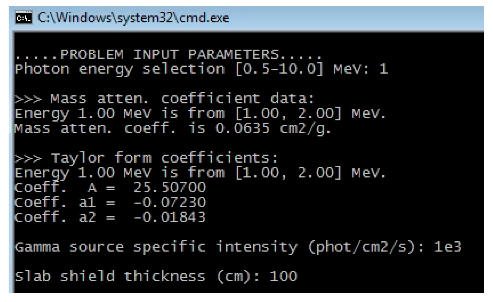
Figure 6 shows basic input data with an on-screen printout of intermediate results of energy-dependent coefficients (mass attenuation and Taylor B-factor). The computational case considered as an example is the gamma disc of radius 25 cm emitting ispotropically 1.0 × 10³ phot/cm2/s in front of the 100 cm-thick concrete slab shield. The point detector is located 200 cm from the gamma disc center.
The compiled modules can be run in two basic modes, depending on what is a search variable: detector buildup flux or a slab shield thickness. The latter is harder to solve since a nonlinear equation with the shield thickness unknown must be found iteratively, using a numerical algorithm for root finding; we have implemented a simple iteration and Newton method [29]. Regardless of the selected mode, the program will print information on material data, shield thickness, B-factors and fluxes. Additional info on CPU timing (total and per-iteration) will be printed for iterative cases. 
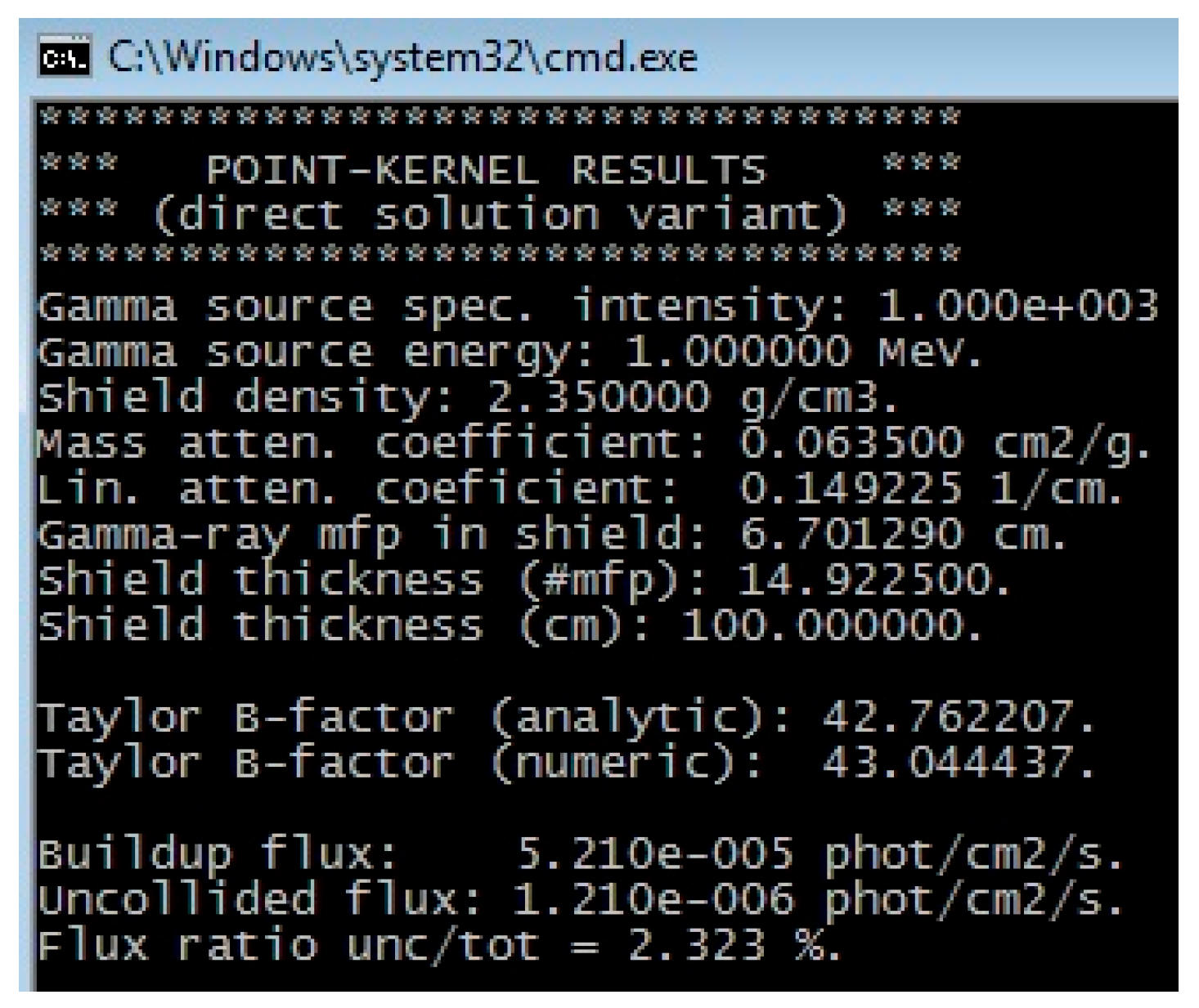
Figure 7 shows the results of the “easy variant” solution for a 100 cm-thick concrete shield and 1 MeV gamma rays emitted from a planar disc 25 cm in radius.
One can notice that the 100 cm-thick concrete slab equals almost 15 mfps for 1 MeV gamma ray. The user should be aware of how various analytical forms of B-factors actually represent different fitting functions of fundamental exposure B-factor data [3] available for shield thickness [1, 20] mfps and gamma-ray energy [0.5, 10] MeV. In our case, we have a good agreement of B-factors: the “numerical” 43.04 is calculated by buildup-to-uncollided flux ratio while the “analytical” 42.7 comes directly from the Taylor formula. Finally, as the shield thickness increases, the uncollided part of the flux takes a decreasing share in the total buildup part.
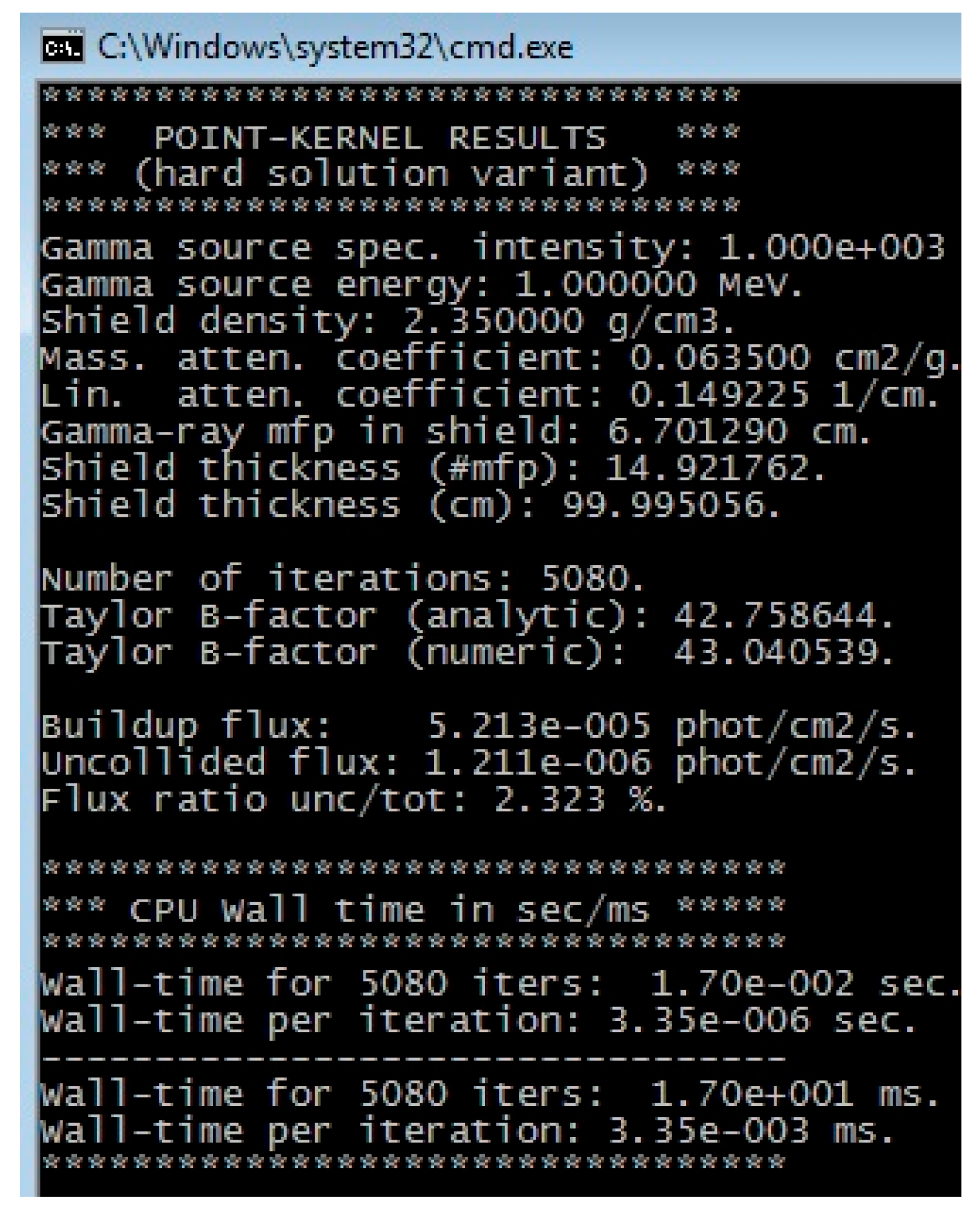
It is interesting to re-run the same shielding problem in backwards, in the “hard variant” solution, where the user inputs a buildup flux of 5.21 × 10⁻⁵ phot/cm2/s and keeps all other input data fixed. The result is shown in Figure 8, where additional info on CPU timing and iterations is provided.
Total of 5080 iterations on shield thickness in mfps (default step of 1.0 × 10⁻³) were needed to practically reproduce the same result. A total wall time of 17 milliseconds was needed on core i-5 CPU at 3.2 GHz, which scales down to 3.36 microseconds per iteration. This wall time was also conservative, since the trail value of shield thickness was selected to be the low-end value from the interval [1, 20], i.e., the worst-case scenario for numerical iterations. The user can easily change the numerical epsilon-value (default 1.0 × 10⁻⁵) controlling the desired flux solution precision.
The final effort was put into a GUI development, written in C++ language [30] as a desktop application using Qt cross-platform [
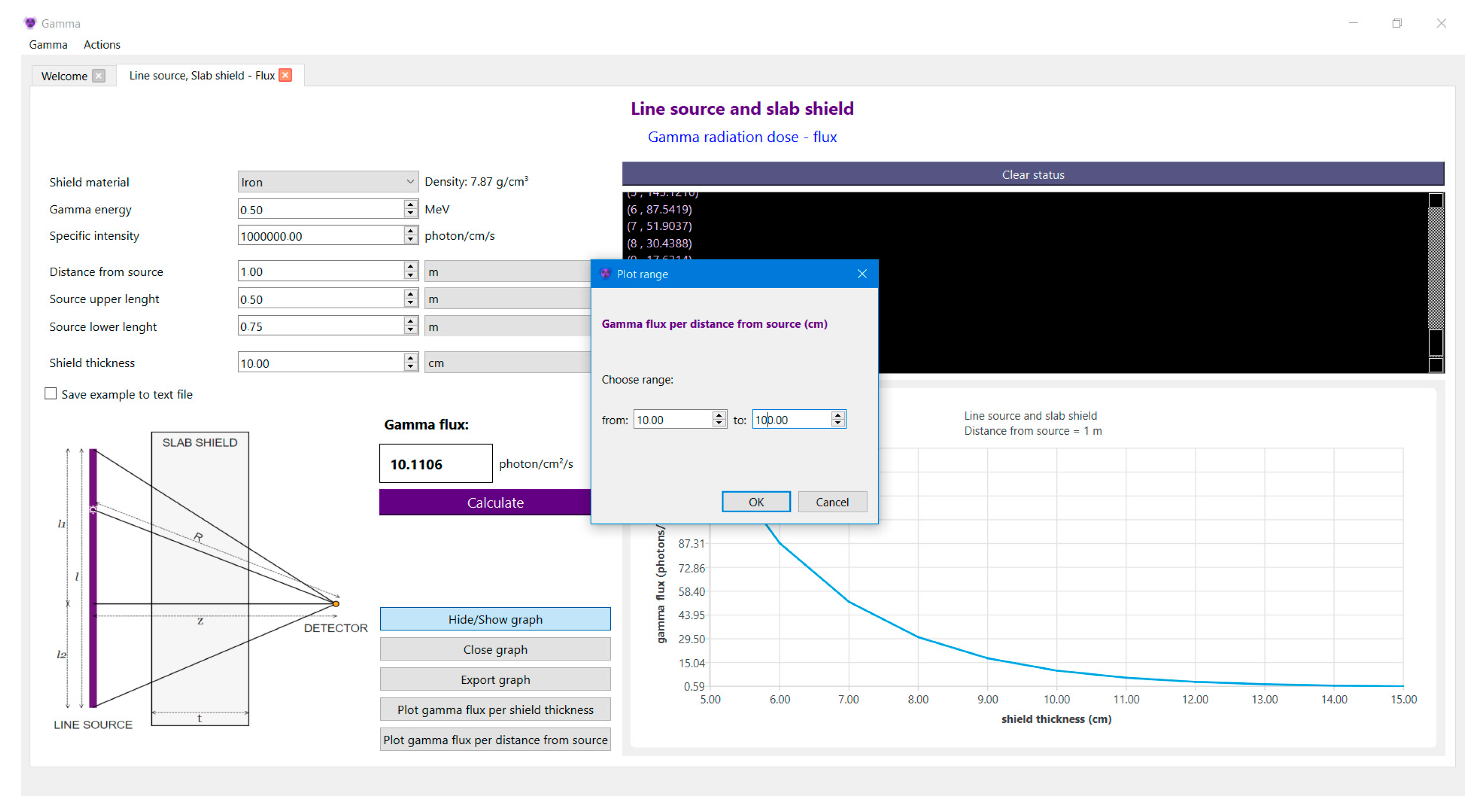
31] development framework as a widget toolkit. The GUI is an interface program between precompiled executable modules and text-based input and output files. The main window in Figure 9 is a tab Widget that holds all open tabs. For both calculation variants, there are input data fields, the option to save the result to a text file, a scheme of geometric configuration, a result field, status and output fields, and options to generate graphs by running the C-application in the loop. The program displays and exports graphs for selected ranges of input data and provides a display of previously saved calculations in a separate tab. All input data are checked when pressing “Calculate” button and any error messages are shown in the status field. This software was implemented with the aim of enabling further development by adding new components/modules such as other source geometric configurations and visualization elements.

5. The PK Program Verification with MAVRIC

The radiation attenuation from a gamma line and slab shield, programming details, and test cases were previously studied in [32]. This section will thus provide PK results for selected case studies related to slab shield and gamma source in the form of finite disc, surface sphere, and volumetric slab source with a self-absorption.

5.1. Isotropic Gamma Disc with a Slab Shield

A series of calculations were performed for an isotropic gamma disc of radius 50 cm and intensity 1 phot/s, emitting 1.27 × 10⁻⁴ phot/cm2/s. The slab shield thickness varied from 1 cm to 50 cm, and two typical shielding materials were considered (iron and concrete). The center of the slab shield was always positioned symmetrically between the source and the point detector at a fixed distance of 100 cm from the source. Two gamma lines of 0.5 MeV and 10 MeV were used independently for source photons, thus enveloping available data on B-factors. The obtained PK solution, with sensitivity study on material, slab shield thickness and gamma-ray energy, was then verified using the MAVRIC shielding sequence of the SCALE6.1.3 code package [19]. The Monaco MC module was used with following options: “v7-27n19g” cross section library, gamma source of 1 phot/s, point detector 100 cm from the gamma disc, and 500 batches with 1000 photons per batch. The CADIS variance reduction (VR) methodology [19,33] was used only for thick shields, especially for iron, while analog MC was used for all others. The average MC relative error on the point detector for all simulation cases was well below 0.1% and CPU time was about 5 min, equal to the MC and VR parts.
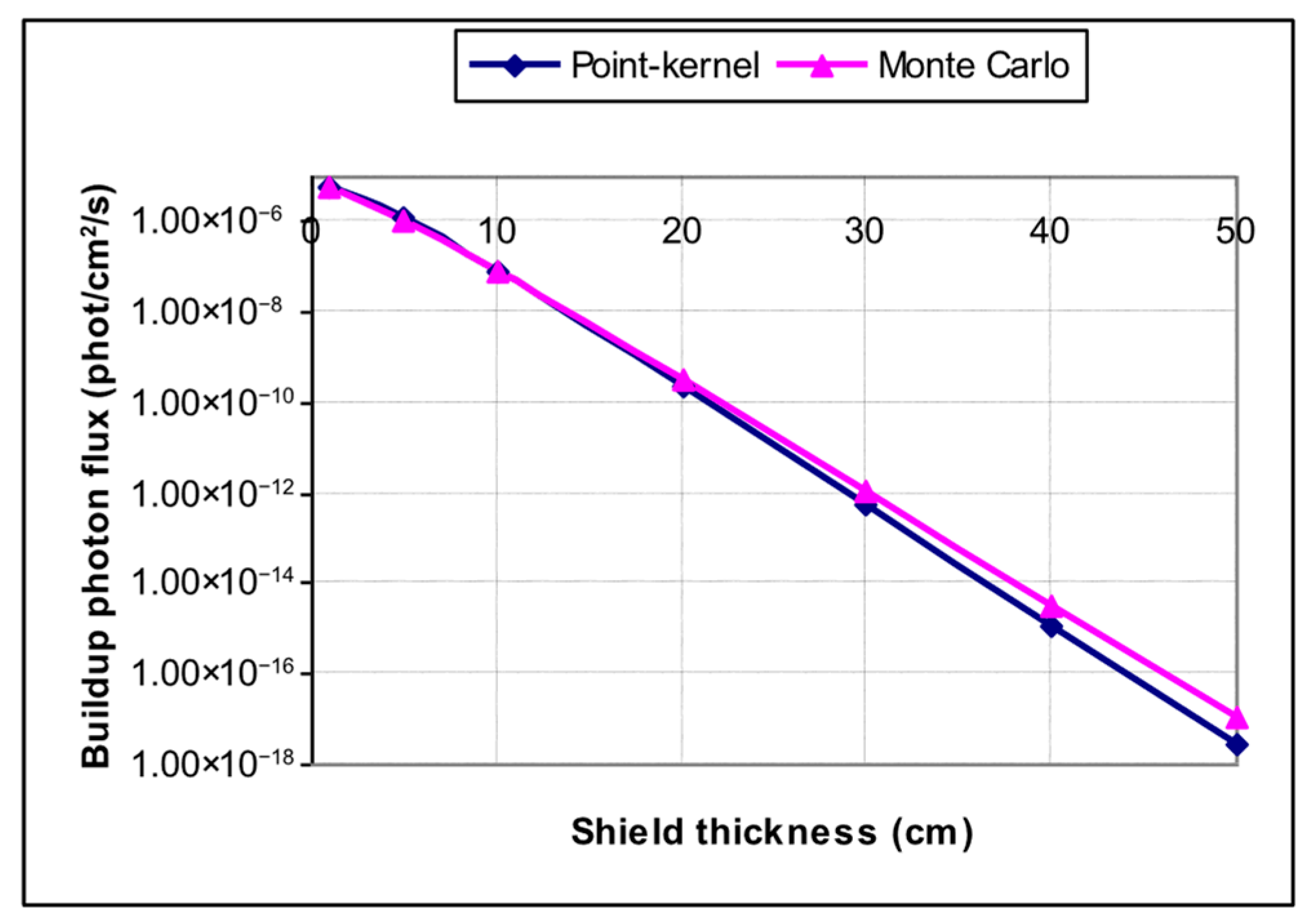
The selected results of 0.5 MeV gamma ray and iron slab shield are presented next. 
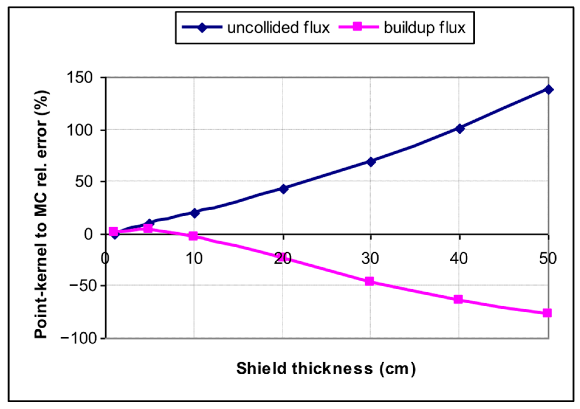
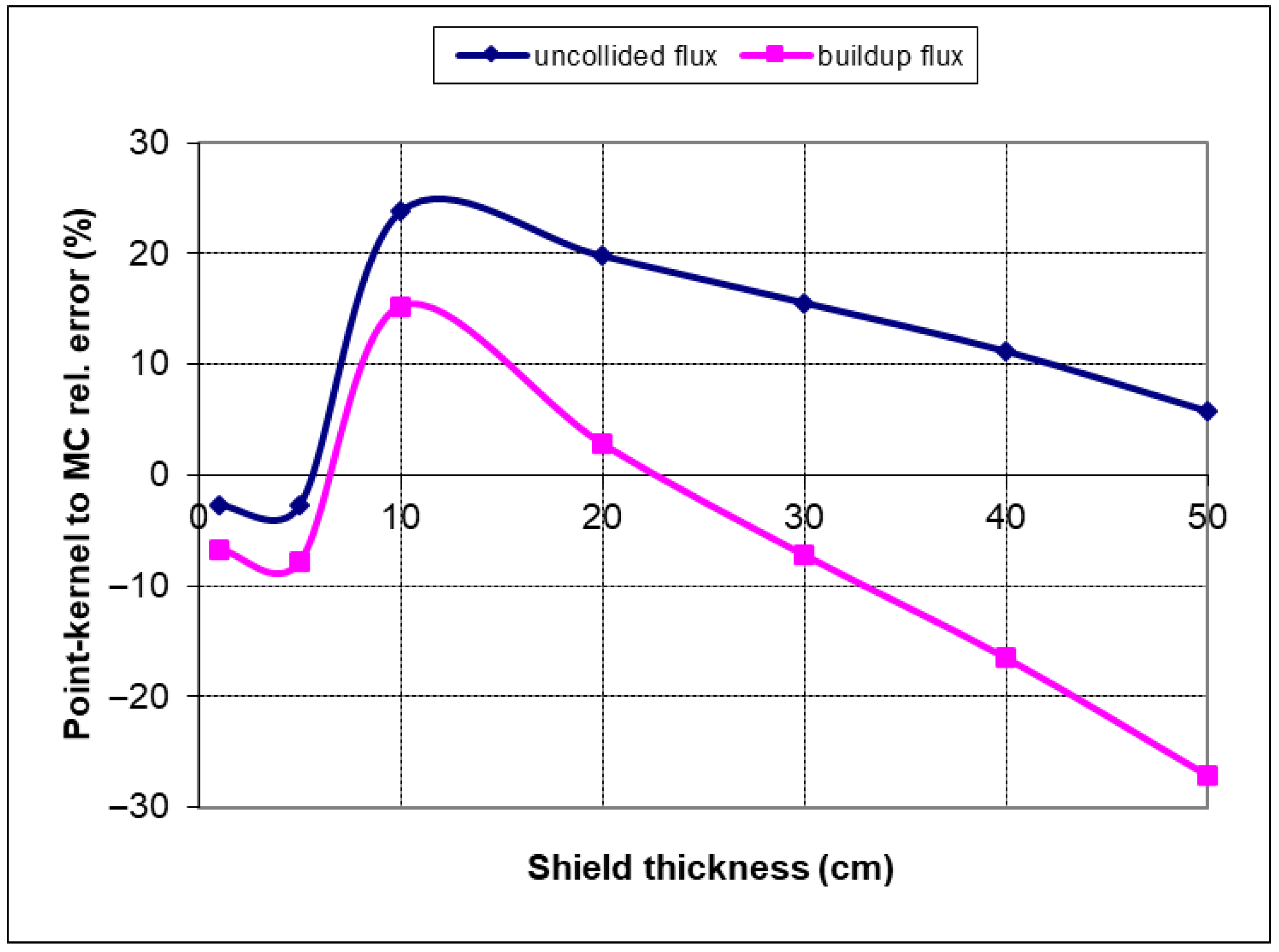
Figure 10 shows a good agreement of PK and MC buildup flux, with PK-to-MC relative errors shown in Figure 11 (with uncollided and buildup parts). Since bulk metal components like RPV will have thickness up to circa 25 cm, these results confirm PK applicability in practical shielding studies, even in high attenuating iron-based shields.
Figure 11 also shows different “conservatism” trends in curves with increasing shield thickness, i.e., the uncollided PK flux is relatively higher than the MC part, but final MC buildup flux proved to be higher. For example, PK buildup flux is 50% lower than MC for 30 cm iron slab, but since the flux value is on the order of 1 × 10⁻¹², this is an acceptable deviation. The inevitable differences have an origin in the MC process, capturing many physical interactions of 0.5 MeV photons that are neglected in a simple PK integration technique.
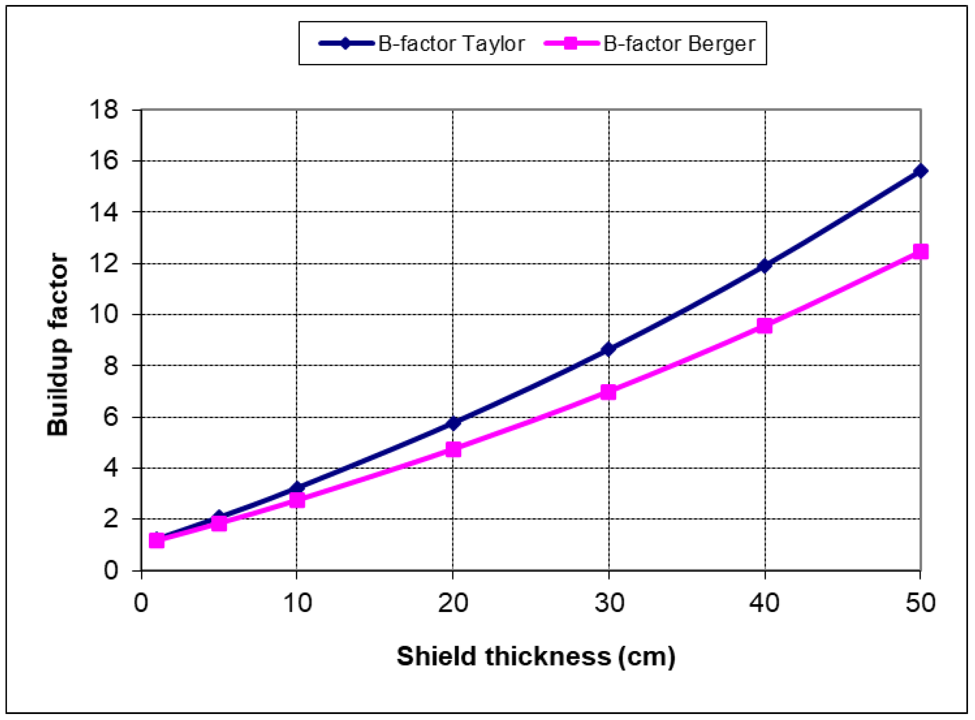
The comparison of B-factors in PK calculations is shown in Figure 12. A good agreement and similar trends in numeric and analytic B-factors were obtained, with B-factor values of over 200 for an iron slab of 50 cm.
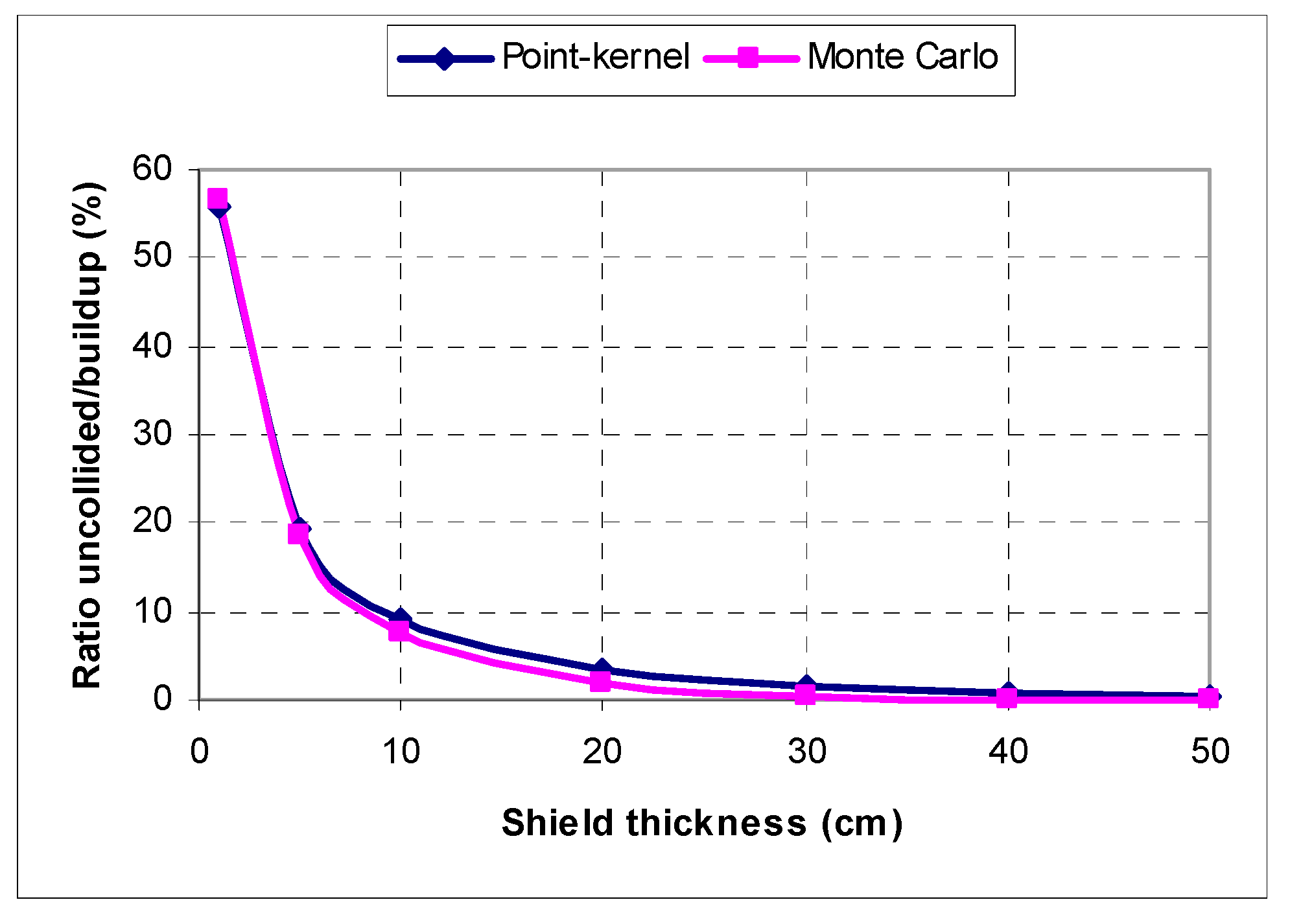
The high-valued B-factor is implying intensive gamma-ray scattering inside the iron shield, so relative ratio of uncollided to buildup flux is expected to be small (Figure 13). One can notice similar uncollided-to-total flux ratio trends in PK and MC solutions, ranging over 50% in 1 cm-thin shield to values well below 10% starting with 10 cm-thick shield.
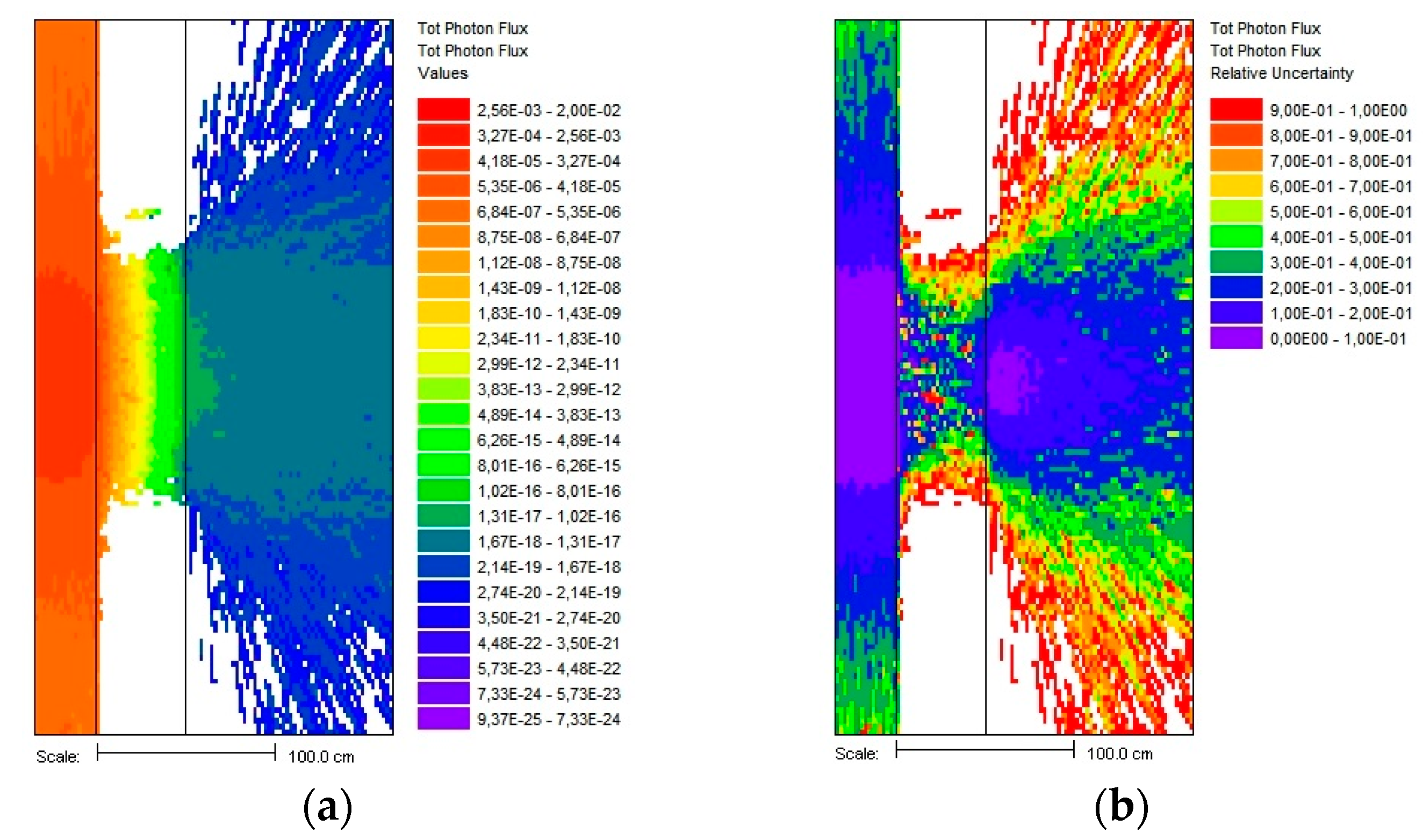
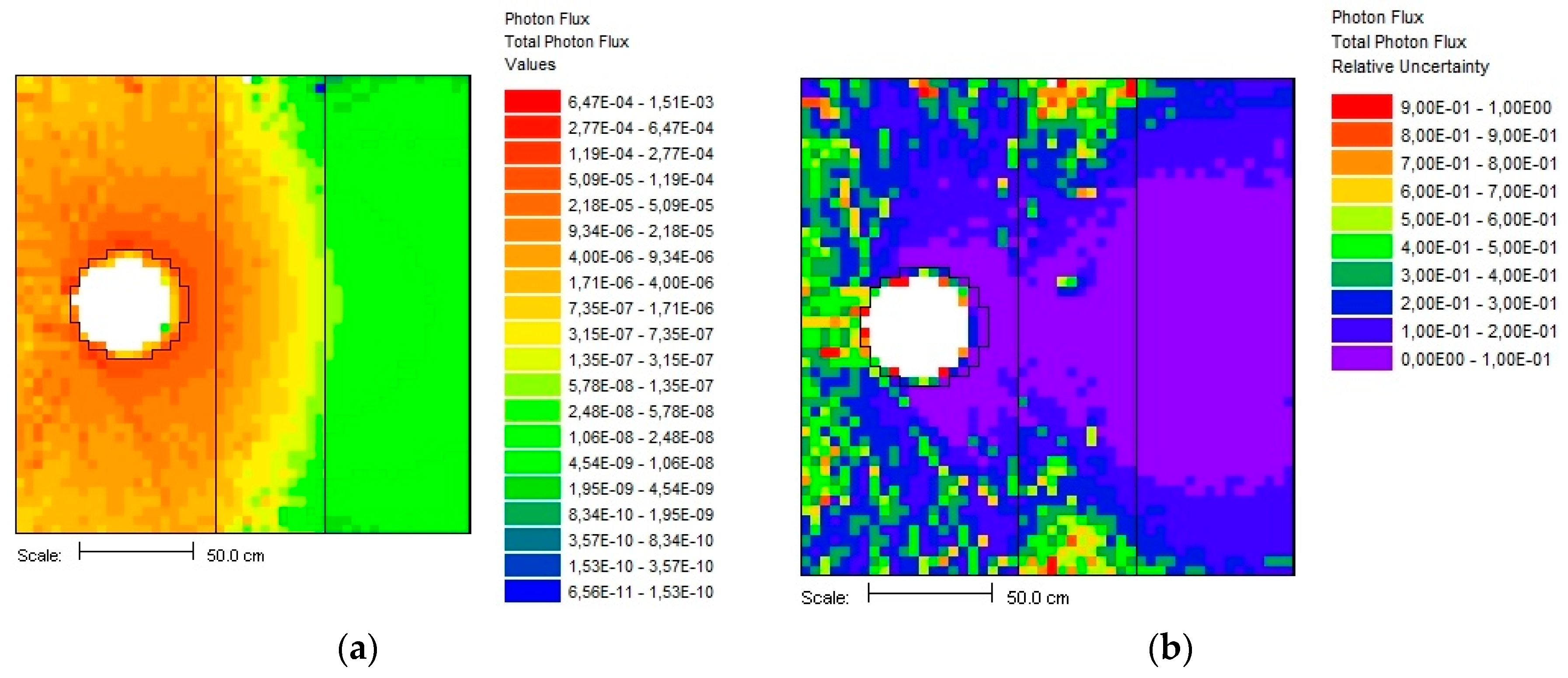
Finally, the mesh tally plot of the MC total flux with relative errors is shown in Figure 14 for 0.5 MeV photons and a 50 cm iron shield. The optimization of gamma-ray transport in the slab shield using the CADIS method is clear, preferentially splitting photons in forward-peaked direction towards the detector. This is a simple case of a deep penetration shielding problem with significant gamma flux attenuation for which effective VR technique is necessary. The CADIS methodology is based on the adjoint SN solver Denovo [34,35], and will optimize the final MC flux only at the point detector location, leaving other spaces weakly populated or with high statistical errors (see Figure 14b). In addition, a point detector has a specific MC estimator form [19] for which ray tracing is used at every photon interaction site, generally increasing the computational time as more details (surfaces) are added in the simulation model.
For comparison, taking 30 cm of iron slab, the PK approach gives a somewhat smaller (about 46%) buildup flux of 5.57 × 10⁻¹³ phot/cm2/s compared to the MC value of 1.04 × 10⁻¹² phot/cm2/s. On the other hand, the PK approach will show drastic speedup, taking only tens of microseconds compared to a 10 min optimized MAVRIC simulation. This advantage of PK can be seen in the initial phase of the shield design, rendering favorable characteristics of shield materials and geometry. The PK method in gamma radiation shielding is still a useful computational tool, but only if used inside its well-known limitations. A specific PK constraint from the perspective of practical usage is the problem of multilayer or composite shields, and it will be inspected later.

5.2. Isotropic Gamma Sphere with a Slab Shield

The PK calculations of the uranium (“black”) sphere 25 cm in radius and point detector located 100 cm from the sphere center are presented next. The concrete slab shield (2.35 g/cm3) of variable thickness (1, 5, 10, 20, 30, 40, and 50 cm) is located symmetrically between the sphere and point detector. The spherical surface source has an intensity of 1 phot/s and is emitting photons of 1 MeV isotropically. The results obtained were again verified using the MAVRIC shielding sequence of SCALE6.1.3 with the same simulation parameters as before. Figure 15 shows a good agreement of PK and MC total fluxes with larger differences of −16% and −27% for slab thicknesses of 40 cm and 50 cm, respectively.
The exceptionally good agreement of PK and MC total gamma flux can be noticed. The slab shield is large with uniform material while point detector is distant relative to the source sphere radius. In this case the source behaves as an isotropic point source concentrated at the sphere center. These conditions strongly fulfill PK “theoretical” assumptions in B-factors, so a high similarity of PK to MC solution was obtained.
The uncollided parts of the flux are practically the same and their ratio to buildup part has a similar behavior. The B-factors are shown in Figure 16 where the Taylor form shows more conservatism over the Berger form.
The relative error of uncollided and buildup flux (PK to MC) is shown in Figure 17 with different trends compared to the gamma disc and slab shield solution. The fundamental shape function is preserved in both cases and decreases with shield thickness.
The MAVRIC photon flux distribution after passing through 50 cm concrete slab is shown in Figure 18 using the CADIS VR technique for optimizing point detector flux.

5.3. Volumetric Gamma Slab with a Slab Shield

These calculations were performed for several combinations of thicknesses and slab shield materials, as presented in Figure 4, so the presented case is for the volume source emitting 1 phot/s of energy 1 MeV in the water layer of 25 cm followed by 25 cm of ordinary concrete. The height and width of slabs were 200 cm, giving in turn 1 × 10⁻⁶ phot/cm3/s in water. The gamma flux was calculated on the slab shield external surface, considering self-absorption in the water. The MAVRIC results of the adjoint gamma flux and weight windows of group 12 (1.0–0.8 MeV) in the “v7_27n19g” library show the “recipe” for MC biasing, i.e., photon splitting is more intense in the vicinity of the detector (Figure 19).
It is clear how 1 MeV photons are attenuated by penetrating the shield, but contribution from other groups is necessary for total photon flux. For the PK approach, this is a composite shield 50 cm in thickness, with an uncollided flux of 2.72 × 10⁻⁸ phot/cm2/s. The obtained buildup factors were 15.9, 14.2 and 10.0 for the Goldstein, Blizard, and Broder methods, respectively. Taking the first one as the most conservative, the buildup flux was 4.32 × 10⁻⁷ phot/cm2/s; this is comparable to the uncollided MC solution of 3.39 × 10⁻⁸ ± 0.04% and total MC flux of 5.51 × 10⁻⁷ ± 0.9%. This PK-to-MC flux difference is only −21.6%, but PK total CPU time was a fraction of second (>1 ms) compared to approximately 12 min for MAVRIC simulation, giving significant speedups for a little loss in accuracy. Of course, increasing the number and/or thickness of shielding layers can generally worsen PK agreement with MC. This behavior is shown next for the concrete layer extending from the initial 25 cm to 100 cm using steps of 25 cm. Figure 20 shows a comparison of PK and MC total gamma flux at external composite shield surface while relative errors of flux components are shown in Figure 21.
One can notice higher values of MC flux components relative to PK and correspondingly increasing relative errors with increasing concrete layer thickness. However, this PK flux is still an acceptable approximation taking that absolute flux value is order of 1 × 10⁻¹³ phot/cm2/s at a composite shield surface. Actually, this flux difference is a consequence of various composite B-factor models, which are compared and shown in Figure 22. The Goldstein model of shield homogenization proved to be the most conservative one, so it was used for all PK buildup flux calculations. For an increasingly thicker concrete shield, these composite B-factor models converge to the same value.
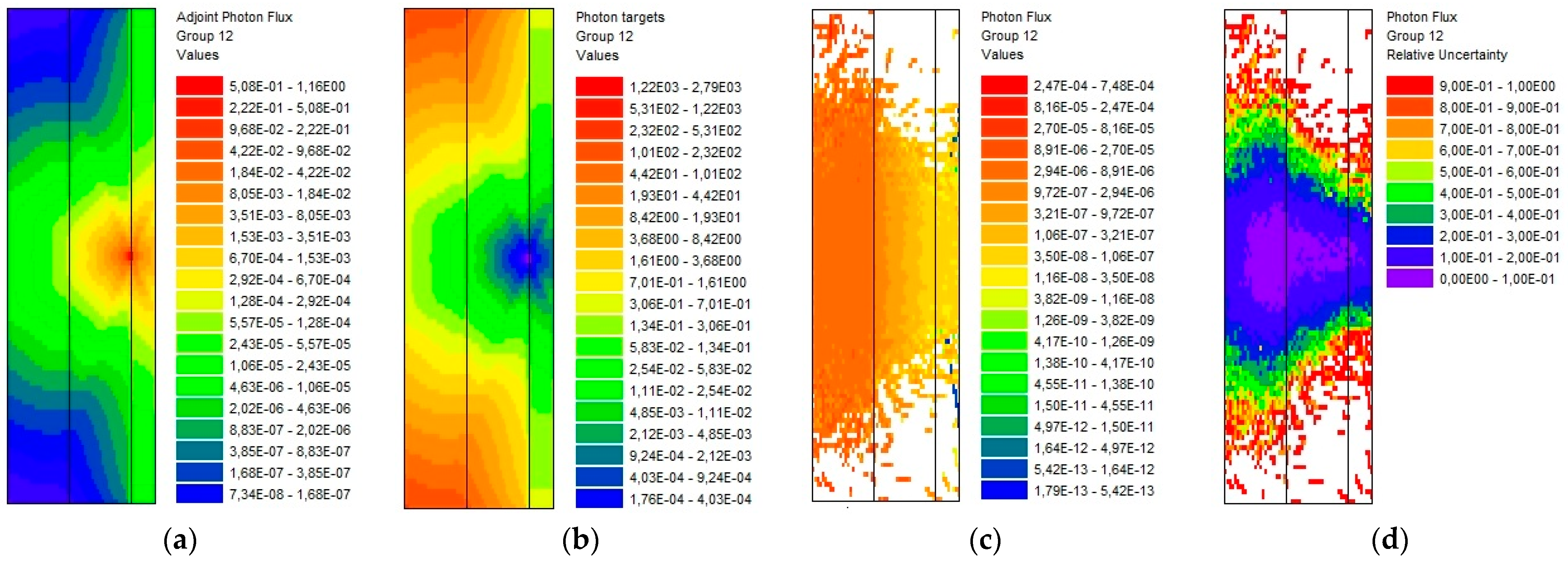
Lastly, the influence of layer ordering on composite B-factor and MC simulation was examined. The specific volume sources were 5 cm lead (SA = 5 × 10⁻⁶ phot/cm3/s) and 50 cm water (SA = 5 × 10⁻⁷ phot/cm3/s). All other control and numerical MAVRIC parameters remained the same. MAVRIC results of total gamma flux with relative errors for lead–water are shown in Figure 23a,b while water–lead results are given in Figure 23c,d. This is a case of composite shield with geometrical setup from Figure 4.
The first ordering of materials (lead–water) proves to be more problematic, since the composite B-factor takes values of 7.6, 26.3 and 12.5 for the Goldstein, Blizard and Broder methods, respectively. The PK uncollided flux was 1.78 × 10⁻⁸ phot/cm2/s and Goldstein buildup flux was 1.35 × 10⁻⁷ phot/cm2/s. These PK values are comparable to MC solution: uncollided flux 2.08 × 10⁻⁸ phot/cm2/s and total flux 5.21 × 10⁻⁷ phot/cm2/s. On the other hand, the second ordering (water-led) produces B-factors of 7.6, 2.4 and 7.7 for the Goldstein, Blizard and Broder methods, respectively. The PK uncollided flux was 1.28 × 10⁻⁸ phot/cm2/s and Goldstein buildup flux was 9.74 × 10⁻⁸ phot/cm2/s. This is in better agreement with the MC solution: uncollided flux 1.49 × 10⁻⁸ phot/cm2/s and total flux 4.89 × 10⁻⁸ phot/cm2/s.
The first layer will cause a continuous gamma spectrum incident on the second layer, so by interchanging the media, one can expect generally different exiting fluxes. Also, by inspecting the B-factor tables, one can see higher values for water than for lead, meaning greater buildup and the propagation of low-energy gamma rays. In lead, however, photoelectric absorption will be a dominant interaction, effectively removing low-energy photons. In turn, if the lead is put first, the gamma-ray buildup in water will propagate toward the detector and increase the buildup flux.

6. Discussion

The development of the PK program for gamma shielding analysis using several basic source distributions and a slab shield has been demonstrated through theoretical and numerical study. The verification of PK results for selected test cases has been carried out by MAVRIC shielding sequence of SCALE6.1.3 code. A generally good agreement of obtained results was noticed for reasonable shield thicknesses and obtained numerical B-factors showed excellent agreement with theoretical values. Noticeable PK deviations from the referent MC solution, which simulates real physical interactions, demonstrate inherent limitations of this fast method, which are generally compensated by a high CPU time speedup.
The PK-to-MC difference will always occur when the PK method is used outside of its “design basis assumptions”, and in our experience, this happens for the following: irregular geometry configurations, composite or multilayered shields with ducts, voids or mazes, complicated sources (in geometry, gamma spectrum, anisotropic emission), non-symmetric shielding and off-line point detectors. In such cases, significant PK underprediction in gamma fluxes is possible relative to the MC solution. The PK method cannot handle gamma-ray scattering (so a corrective B-factor is needed), streaming radiation-augmenting angle-dependent radiation peaks with localized radiological significance, real-life sources with energy-spatial gradients, radiation backscattering from surrounding structures, albedos, and similar boundary conditions. For such specific purposes, the MC should be used as a standard simulation tool for coupled neutron-photon transport, but this burdens computational hardware and requires user experience in transport theory.

7. Conclusions

The future work on PK program expansion will upgrade GUI to better assist user with input/output data handling and to provide additional visualization of geometry setup and calculated fluxes. The next program version should expand source shapes, materials, options for composite shields, standard flux-to-dose factors, and a more elaborate geometrical progression B-factor form for cross-verification. Machine learning algorithms will be integrated in the future workflow primarily for composite B-factor determination. Upon completion of these tasks, we will consider other prospects for the PK program upgrade, such as producing new MC-based and ML-based attenuation kernels as opposed to available tabulated B-factors for standard sources and shield geometries.

Author Contributions

Conceptualization, M.M. and K.T.; methodology, M.M.; software, M.M.; validation, M.M., K.T. and S.Š.; formal analysis, M.M., K.T. and S.Š.; investigation, M.M. and P.D.; resources, M.M., K.T. and P.D.; data curation, M.M., K.T. and S.Š.; writing—original draft preparation, M.M.; writing—review and editing, M.M., K.T., S.Š. and P.D.; visualization, M.M. and S.Š.; supervision, M.M. and K.T.; project administration, K.T. and S.Š.; funding acquisition, S.Š. All authors have read and agreed to the published version of the manuscript.

Funding

This work was supported by the Croatian Science Foundation under the project number HRZZ-IP-2024-05-4011. The APC was funded by the Croatian Science Foundation under the project number HRZZ-IP-2024-05-4011. Applsci 15 07795 i001

Institutional Review Board Statement

Not applicable.

Informed Consent Statement

Not applicable.

Data Availability Statement

The original contributions presented in the study are included in the article and further inquiries can be directed to the corresponding author.

Conflicts of Interest

The authors declare no conflicts of interest.

Abbreviations

The following abbreviations are used in this manuscript:
PKPoint-kernel method for gamma flux attenuation calculations
MCMonte Carlo method for solving particle transport
B-factorBuildup factor of gamma radiation inside shields
ORNLOak Ridge National Laboratory in USA
GUIGraphical User Interface for PK computational modules
MAVRICMonaco with Automated Variance Reduction based on Importance Calculations; shielding analytical sequence of SCALE6.1.3 code package
CADISConsistent Adjoint Driven Importance Sampling
SNMethod of discrete ordinates for solving Boltzmann transport equation
CPUCentral Processing Unit
VRVariance Reduction
RPVReactor Pressure Vessel

Appendix A

CADIS VR Methodology Overview

MAVRIC is the main shielding sequence of SCALE6.1.3 code package and is implementing CADIS approach to automate calculation and usage of deterministic VR parameters (biased source and importance map) calculated by SN code Denovo for multigroup MC code Monaco [19]. The user is required, besides preparing complete input listing for a MC model, to enter an additional block of parameters typical for SN solvers: structured mesh overlaying the physical geometry, SN/PN parameters (angular quadrature and Legendre order for cross section polynomial expansion), spatial differencing option, macromaterials for improving geometry discretization, and various control/numeric options. Denovo will then produce a quick estimate of the multigroup fluxes used for generating VR parameters that are consistent with particle weights and work in tandem. CADIS will thus allow the user to optimize MC result at one specific location (i.e., point detector) which is quantified by the FOM (Figure of Merit) factor, combining CPU time needed to achieve the MC result of desired precision. Since CADIS is already well documented, only a brief overview of fundamental equations is provided here.
To calculate the reaction rate R at some point detector using the unit source q, the scalar flux ϕ is convoluted with a detector response function σ as the following integral over detector volume Vd and energy E of reaction interest:
R = V d , E σ d ( r , E ) ϕ ( r , E ) d V d E .
Using the theory of general reciprocity [35], we can arrive alternatively to R by integrating the source q with an adjoint scalar flux ϕ calculated from the corresponding adjoint problem (detector response function σ is an adjoint source q):
R = V s , E q ( r , E ) ϕ ( r , E ) d V d E .
The quick SN estimate of the adjoint flux by Denovo is allowing calculation of a biased source distribution to be used for source particle sampling
q ^ ( r , E ) = q ( r , E ) ϕ ( r , E ) R ,
which means that particle source weight is in accordance with mesh importance map (or weight windows) used for transport biasing, i.e., splitting and rouletting:
w ¯ ( r , E ) = R ϕ ( r , E )
The last two equations form consistent energy-dependent, mesh-based VR parameters that work in tandem during a final MC simulation of Monaco.

References

  1. Schaeffer, N.M. Reactor Shielding for Nuclear Engineers; U.S. Atomic Energy Commission Office of Information Services: Springfield, VA, USA, 1976. [Google Scholar]
  2. Glasstone, S.; Sesonske, A. Nuclear Reactor Engineering—Reactor Design Basics, 4th ed.; Chapman & Hall: New York, NY, USA, 1994. [Google Scholar]
  3. Goldstein, H. Fundamental Aspects of Reactor Shielding; Addison-Wesley Publishing Company, Inc.: Boston, MA, USA, 1959. [Google Scholar]
  4. Trubey, D.K. Early Test Facilities and Analytic Methods for Radiation Shielding; History and Evolution of Buildup Factors. In Proceedings of the a Special Session for the Radiation Protection and Shielding Division at the American Nuclear Society Winter Meeting, Chicago, IL, USA, 15–20 November 1992. [Google Scholar]
  5. Kang, S.; Lee, S.; Chung, C.; Lee, C.; Lee, J. Development of Point Kernel Shielding Analysis Computer Program Implementing Recent Nuclear Data and Graphic User Interfaces. J. Radiat. Prot. 2001, 26, 215–224. [Google Scholar]
  6. Trontl, K.; Šmuc, T.; Pevec, D. Support vector regression model for the estimation of γ-ray buildup factors for multi-layer shields. Ann. Nucl. Ene. 2007, 34, 939–952. [Google Scholar] [CrossRef]
  7. Subbaiah, K.V.; Sarangapani, R. IGSHIELD: A new interactive point kernel gamma ray shielding code. Ann. Nucl. Ene. 2008, 35, 2234–2242. [Google Scholar] [CrossRef]
  8. Zeb, J.; Wasim, M. U-Shielder—an open source software for the estimation of gamma shielding using depleted uranium. Radioprotection 2017, 52, 273–275. [Google Scholar] [CrossRef]
  9. Yang, L.; Liu, Y.; Peng, M.; Li, M. A gamma-ray dose rate assessment method for arbitrary shape geometries based on voxelization algorithm. Rad. Phy. Chem. 2019, 158, 122–130. [Google Scholar] [CrossRef]
  10. Li, M.; Xu, Z.; Li, W.; Yang, J.; Yang, M.; Lu, H.; Dai, X. MIGSHIELD: A new model-based interactive point kernel gamma ray shielding package for virtual environment. Nucl. Eng. Tech. 2020, 52, 1557–1564. [Google Scholar] [CrossRef]
  11. Kumar, M.H.; Mammen, S. 3DGShield: A new 3D gamma ray shielding code for arbitrary source and shield geometry based on point kernel technique. Ann. Nucl. Ene. 2021, 159, 108352. [Google Scholar]
  12. Li, C.; Song, Y.; Zhang, Z.; Mao, J.; Yuan, W.; Wang, B. A Novel and High-Precision Method for Calculating the γ-Ray Build-Up Factor for Multilayer Shields. Sci. Tech. Nuc. Inst. 2021, 2021, 1–15. [Google Scholar] [CrossRef]
  13. Xu, Z.; Li, M.; Zou, B.; Yang, M. A GPU-based point kernel gamma dose rate computing code for virtual simulation in radiation-controlled area. Nucl. Eng. Tech. 2023, 55, 1966–1973. [Google Scholar] [CrossRef]
  14. Sun, P.; Zhang, H.; Xing, L.; Zhong, B.; Ying, Y.; Shen, H. NPTS-PK: A new point kernel code for fast calculation of 3D gamma radiation field. Rad. Phy. Chem. 2025, 226, 112329. [Google Scholar] [CrossRef]
  15. Chen, J.; Li, R.; Chen, Y.; Cao, C.; Liang, J. POKER: A new point kernel 3D radiation field characterization code with stratified and deep shielding capabilities. Nuc. Eng. Tech. 2025, 57, 1–12. [Google Scholar] [CrossRef]
  16. Matijević, M.; Ječmenica, R.; Grgić, D. Spent Fuel Pool Dose Rate Calculations Using Point Kernel and Hybrid Deterministic-Stochastic Shielding Methods. J. Energy 2016, 65, 151–161. [Google Scholar]
  17. Trontl, K.; Pevec, D.; Matijević, M. Monte Carlo Codes for Neutron Buildup Factors. J. Energy 2013, 62, 171–179. [Google Scholar] [CrossRef]
  18. Dučkić, P.; Trontl, K.; Grgić, D.; Matijević, M. Point Kernel Modification Including Support Vector Regression Neutron Buildup Factor Models. J. Energy 2019, 68, 156–170. [Google Scholar]
  19. Scale: A Comprehensive Modeling and Simulation Suite for Nuclear Safety Analysis and Design, ORNL/TM-2005/39, Version 6.1, June 2011, Available from Radiation Safety Information Computational Center at Oak Ridge National Laboratory as CCC-785. Available online: https://www.ornl.gov/scale (accessed on 26 May 2025).
  20. Lewis, E.E.; Miller, W.F., Jr. Computational Methods of Neutron Transport; American Nuclear Society, Inc.: Westmont, IL, USA, 1993. [Google Scholar]
  21. Harima, Y. An Approximation of Gamma-Ray Buildup Factors by Modified Geometrical Progression. Nucl. Sci. Eng. 1983, 83, 299–309. [Google Scholar] [CrossRef]
  22. Harima, Y. An Historical Review and Current Status of Buildup Factor Calculations and Applications. Radiat. Phys. Chem. 1993, 41, 631–672. [Google Scholar] [CrossRef]
  23. Wood, J. Computational Methods in Reactor Shielding, 1st ed.; Pergamon Press: Oxford, UK, 1982. [Google Scholar]
  24. Shure, K.; Wallace, O.J. Compact Tables of Functions for Use in Shielding Calculations. Nucl. Sci. Eng. 1975, 56, 84–94. [Google Scholar] [CrossRef]
  25. Kernighan, B.W.; Ritchie, D.M. The C Programming Language, 2nd ed.; Prentice Hall PTR: Saddle River, NJ, USA, 1988. [Google Scholar]
  26. The GNU C Compiler. Available online: https://gcc.gnu.org/ (accessed on 26 May 2025).
  27. The GNU C Language Intro and Reference Manual. Available online: https://www.gnu.org/software/c-intro-and-ref/manual/ (accessed on 26 May 2025).
  28. Press, W.H.; Teukolsky, S.A.; Vetterling, W.T.; Flannery, B.P. Special Functions. In Numerical Recipes in C—The Art of Scientific Computing, 2nd ed.; Cambridge University Press: New York, NY, USA, 1992; pp. 222–225. [Google Scholar]
  29. Press, W.H.; Teukolsky, S.A.; Vetterling, W.T.; Flannery, B.P. Root Finding and Nonlinear Sets of Equations. In Numerical Recipes in C—The Art of Scientific Computing, 2nd ed.; Cambridge University Press: New York, NY, USA, 1992; pp. 347–393. [Google Scholar]
  30. Stroustrup, B. The C++ Programming Language, 4th ed.; Pearson Education, Inc.: Upper Saddle River, NJ, USA, 2013. [Google Scholar]
  31. Qt documentation. Available online: https://doc.qt.io/ (accessed on 10 May 2025).
  32. Matijević, M.; Kaselj, A.; Trontl, K. Calculation of Sievert Integral for Point-Kernel Shielding Applications. In Proceedings of the 14th International Conference of the Croatian Nuclear Society, Zadar, Croatia, 9–12 June 2024. [Google Scholar]
  33. Wagner, J.C.; Haghighat, A. Automated Variance Reduction of Monte Carlo Shielding Calculations Using the Discrete Ordinates Adjoint Function. Nucl. Sci. Eng. 1998, 128, 186–208. [Google Scholar] [CrossRef]
  34. Evans, T.M.; Stafford, A.S.; Slaybaugh, R.N.; Clarno, K.T. Denovo: A new three-dimensional parallel discrete ordinates code in SCALE. Nucl. Tech. 2010, 171, 171–200. [Google Scholar] [CrossRef]
  35. Bell, G.I.; Glasstone, S. Nuclear Reactor Theory; Van Nostrand Reinhold Company, Litton Educational: New York, NY, USA, 1970. [Google Scholar]
Figure 1. Gamma disc uncollided flux as a superposition of point sources [2].
Applsci 15 07795 g001
Figure 2. Geometry setup for gamma line and slab shield [2].
Applsci 15 07795 g002
Figure 3. Point detector response from the spherical gamma source [23].
Applsci 15 07795 g003
Figure 4. Geometry arrangement of the volume source slab and parallel slab shield [23].
Applsci 15 07795 g004
Figure 5. The PK program’s main selection menu.
Applsci 15 07795 g005
Figure 6. The PK program input parameters overview.
Applsci 15 07795 g006
Figure 7. The PK program results (“easy variant” solution).
Applsci 15 07795 g007
Figure 8. The PK program results (“hard variant” solution).
Applsci 15 07795 g008
Figure 9. The main window of PK GUI program for gamma line and slab shield.
Applsci 15 07795 g009
Figure 10. Comparison of PK and MC buildup flux.
Applsci 15 07795 g010
Figure 11. PK to MC relative errors of buildup flux for 0.5 MeV gamma rays.
Applsci 15 07795 g011
Figure 12. Comparison of “numeric” and “analytic” B-factor.
Applsci 15 07795 g012
Figure 13. Ratio of uncollided to buildup flux (PK and MC).
Applsci 15 07795 g013
Figure 14. MC total flux solution for 0.5 MeV photons using CADIS technique: (a) mesh tally total gamma flux; (b) relative errors of mesh tally flux.
Applsci 15 07795 g014
Figure 15. Total gamma flux (PK and MC) from the 1 MeV gamma-ray sphere.
Applsci 15 07795 g015
Figure 16. Buildup factors for 1 MeV gamma-ray sphere in concrete shield.
Applsci 15 07795 g016
Figure 17. PK to MC relative error for 1 MeV gamma rays in a concrete shield (spherical source).
Applsci 15 07795 g017
Figure 18. Total MC flux distribution of 1 MeV photons leaving spherical surface using CADIS technique: (a) mesh tally total gamma flux; (b) relative errors of mesh tally flux.
Applsci 15 07795 g018
Figure 19. MAVRIC results (group 12, 1.0–0.8 MeV) for the slab source with self-absorption: (a) adjoint SN gamma flux; (b) weight windows; (c) MC photon flux; (d) MC photon flux relative error. The rightmost layer is part of the global unit filled with dry air.
Applsci 15 07795 g019
Figure 20. Total gamma flux (PK and MC) from 1 MeV gamma-ray volume source.
Applsci 15 07795 g020
Figure 21. PK to MC relative error for 1 MeV gamma ray in concrete shield (volume source).
Applsci 15 07795 g021
Figure 22. Comparison of composite B-factors in concrete shield.
Applsci 15 07795 g022
Figure 23. Total MC flux with relative errors for the slab source with self-absorption and slab shield: (a,b) lead–water composite shield; (c,d) water–lead composite shield. The rightmost layer is part of the global unit filled with dry air.
Applsci 15 07795 g023
Disclaimer/Publisher’s Note: The statements, opinions and data contained in all publications are solely those of the individual author(s) and contributor(s) and not of MDPI and/or the editor(s). MDPI and/or the editor(s) disclaim responsibility for any injury to people or property resulting from any ideas, methods, instructions or products referred to in the content.

