Abstract
Hydrogen is a promising fuel in the current transition to zero-net CO2 emissions. However, most practical combustion equipment is not yet ready to burn pure hydrogen without adaptation. In the meantime, blending hydrogen with natural gas is an interesting option. This work reports a computational study of the performance of swirl-stabilized natural gas/hydrogen flames in a novel combustion chamber design. The combustor employs an air-staging strategy, introducing secondary air through a top-mounted plenum in a direction opposite to the fuel jet. The thermal load is fixed at 5 kW, and the effects of fuel composition (hydrogen molar fraction ranging from zero to one), excess air coefficient (λ = 1.3, 1.5 or 1.7), and primary air fraction (α = 50–100%) on the velocity, temperature, and emissions are analysed. The results show that secondary air changes the flow pattern, reducing the central recirculation zone and lowering the temperature in the primary reaction zone while increasing it further downstream. Secondary air improves the performance of the combustor for pure hydrogen flames, reducing NO emissions to less than 50 ppm for λ = 1.3 and 50% primary air. For natural gas/hydrogen blends, a sufficiently high excess air level is required to keep CO emissions within acceptable limits.
1. Introduction
The world is facing an unprecedented and fast transformation in energy supply sources. In the 1970s, fossil fuels accounted for more than 80% of global primary energy consumption [1]. Nowadays, the share of renewable energy sources is rising sharply, and projections indicate that fossil fuels will play a significantly reduced role in the near future [2]. This shift in the global energy paradigm is primarily driven by concerns over climate change, which is strongly linked to greenhouse gas emissions. A substantial portion of these emissions originates from the combustion of fossil fuels, making their reduction a key strategy in mitigating global warming [3]. Moreover, renewable energy sources help reduce dependence on external energy supplies, thereby enhancing resilience to pandemics, environmental disasters, and geopolitical disruptions. However, the shift towards alternative energy sources requires gradual implementation and cannot be accomplished in a short timeframe [4].
Meanwhile, cleaner fuels are emerging as promising alternatives to traditional fossil fuels. Among them, hydrogen stands out as a viable option [5]. However, several challenges must be addressed before hydrogen can be widely adopted. Although hydrogen is the most abundant element in the universe, it does not exist in a free state on Earth and is instead bound to other elements in compounds such as water and methane. Extracting hydrogen requires energy-intensive processes such as water electrolysis or methane reforming, which should ideally be powered by renewable energy sources to minimize carbon emissions [6]. Another major challenge is the lack of infrastructure for hydrogen transport and distribution. While existing natural gas pipelines can accommodate hydrogen when blended in low concentrations, large-scale hydrogen transport remains a technical and economic hurdle [7]. Additionally, hydrogen storage presents significant challenges due to its low density, high diffusivity, material compatibility issues arising from hydrogen embrittlement, high permeation and leakage potential, and the associated risks of explosion. Safe and efficient storage solutions are under development but require further advancements for widespread implementation [7].
In addition to the problems associated with production, transport, and storage, the use of hydrogen as a fuel is also challenging. In fact, hydrogen has a high laminar flame speed, making it prone to flashback in premixed combustion systems, and a low ignition energy and extended flammability range, that may cause premature or unintended ignition. Accordingly, it cannot be readily burnt [8]. An interesting alternative that has been widely investigated, particularly in the last 2 decades, is the blending of hydrogen with natural gas or methane [9].
The present work reports a computational investigation of a novel swirl combustor burning mixtures of natural gas (NG) and hydrogen, with the molar fraction of hydrogen in the fuel ranging from 0% to 100%. Among the methods used to stabilize turbulent flames, swirl is one of the most widely used ones, and several works addressing the combustion of CH4/H2 or NG/H2 mixtures in swirl burners have been reported, as summarized below.
Unconfined swirling flames were experimentally studied by Kim et al. [10], who focused on the impact of hydrogen enrichment and swirl strength in methane–air premixed flames in a swirl-stabilized laboratory-scale burner, at constant thermal power. They found that hydrogen accelerates chemical reactions, increases the temperature, and reduces the recirculation flow in the reaction zone. The NO concentration in the reaction zone decreased with the increase in the hydrogen content at low swirl intensity, while an opposite trend was found at high swirl intensity. The influence of the hydrogen content and swirl strength was further investigated by Kashir et al. [11] for an unconfined bluff-body stabilized swirling burner, usually referred to as a Sydney swirl burner. Their numerical simulations reveal that hydrogen addition reduces the flame length, but this effect is attenuated with the increase of the swirl number. The NO reaction pathways in an unconfined swirl burner at constant thermal power were computationally investigated by Wang et al. [12]. They found that, for the studied conditions, prompt NO contributes the most to NO formation for hydrogen molar fractions up to 60%, even though its relative contribution decreases with the increase of the hydrogen content. Although thermal NO becomes more important with hydrogen addition, it only accounts for about 25% of the total NO emissions at 60% H2 (vol.) in the fuel due to the relatively low flame temperatures caused by co-flow air and dilution. The importance of the NNH (diazenyl radical) pathway increases significantly, contributing to around 20% of the total NO emissions with hydrogen enrichment of 60%. The N2O pathway for NO production is the least important.
Most studies on swirling flames have been conducted under confined conditions for premixed, non-premixed of partially premixed flames. The influence of the swirl intensity on the premixed combustion of natural gas/hydrogen or methane/hydrogen mixtures was explored by Du et al. [13] and Elbayoumi et al. [14]. The former study found that CO and NO emissions gradually decreased with the increase of the swirl intensity, while combustion performance improved when the swirl angle was set to 45°. The latter one reported that increasing swirl intensity enlarges the inner recirculation zone, shortens the flame, and raises the temperature.
The flame structure of CH4/H2 flames has been extensively investigated. Cozzi and Coghe [15] studied non-premixed flames with hydrogen contents ranging from 0% to 100% in a co-flow swirl burner, maintaining a constant volumetric fuel flow rate. Their results showed that hydrogen addition shortened the flame, bringing it closer to the burner head. Building on their previous work [10], Kim et al. [16] found that under confined conditions, adding hydrogen to methane enhanced the flame stability, shifted the reaction zone upstream, and increased the peak flame temperature. The increase in flame temperature with hydrogen addition was corroborated by other studies [17,18,19], while the reduction in flame size was confirmed by Rajpara et al. [18] and Ge et al. [20]. In the latter studied, Ge et al. observed that the flame structure remained nearly unchanged for hydrogen contents up to 5%. However, at concentrations above 11%, the flame shrank and expanded towards the wall.
Most studies on emissions from swirling CH4/H2 flames have reported a decrease in CO emissions with increasing hydrogen molar fraction in the fuel, e.g., [17,18,20,21], Liu et al. [22]. This reduction is primarily due to the lower carbon content in the fuel and the enhanced formation of OH radicals with higher hydrogen content, which promote CO oxidation. However, the extent of CO reduction varies between studies. Some, like Ge et al. [20], observed a small decrease, while others, such as Rajpara et al. [18], reported a significant reduction. Moreover, some studies have reported opposite trends. Patel and Shah [23] experimentally investigated hydrogen enrichment in swirling and non-swirling inverse diffusion flames. At constant energy per unit mass input, CO emissions decreased with increasing hydrogen content. However, when hydrogen enrichment was conducted at a constant fuel volumetric flow rate, CO emissions increased. This latter trend aligns with the findings of Cozzi and Coghe [15], who observed a monotonic increase in CO emissions for hydrogen molar fractions up to 0.8 in a co-flow swirl burner while maintaining a constant volumetric fuel flow rate.
Most studies have reported an increase in NOx emissions with higher hydrogen content in the fuel (e.g., [15,16,18,20,24,25]). This is primarily due to the rise in adiabatic flame temperature, which promotes thermal NO formation, typically dominant at temperatures above 1800 K. Additionally, higher hydrogen content increases the concentration of O, H, and OH radicals, further enhancing NO formation. However, the magnitude of the NOx increase varies widely among studies, being small in some (e.g., [18]) and significant in others (e.g., [25]). Kim et al. [16] pointed out that increasing the swirl intensity or the excess air could help mitigate NOx emissions. Interestingly, not all studies found a direct correlation between hydrogen content and NOx emissions. Schefer et al. [21] observed no significant effect, while Patel and Shah [23] reported lower NOx emissions with hydrogen enrichment at a constant fuel volumetric flow rate. These discrepancies highlight that the sensitivity of both CO and NOx emissions to fuel composition depends on burner design, operating conditions, and the specific constraints of each study, such as maintaining constant the Reynolds number, the thermal input, the volumetric fuel flow rate, etc.
The stability of CH4/H2 turbulent swirling flames has also been addressed in the literature. Shanbhogue et al. [26] experimentally investigated the transition between stable and unstable combustion in a swirl-stabilized premixed combustor. They observed that combustion remained stable at low equivalence ratios but developed harmonic oscillations above a critical equivalence ratio, regardless of the fuel composition. Ren et al. [27] conducted a numerical investigation of a swirl vortex–tube combustor. Their results show that the local flow velocity near the reaction zone decreases, while the tangential velocity remains high due to the strong vortex flow. This effect inhibits blow-out and enhances stability. Xia et al. [28] performed a numerical study on flashback in a bluff–body swirl burner, demonstrating that the preferential diffusion of H2 significantly increases flashback susceptibility.
Marragou et al. [29] experimentally investigated flame stabilization mechanisms and emissions in a dual swirl low-NOx burner. Hydrogen was introduced into the combustor through a central tube with an internal swirler, while a methane–air mixture was injected via an annular swirler. The swirl imparted to the hydrogen stream improved flame stabilization, resulting in low NOx emissions. Additionally, a small recess in the central injector significantly extended the operability range of the burner. NOx emissions were further reduced at higher thermal power for a fixed equivalence ratio. Laera et al. [30] conducted large eddy simulations of these flames. Their results indicated that while hydrogen injection had a minimal impact on the overall flame structure, it led to a more intense reaction. Pignatelli et al. [31] investigated the influence of a pilot flame on swirling turbulent premixed CH4/H2 flames in a laboratory gas turbine combustor. Their experiments demonstrated that the pilot flame extended the stable flame regime and that the lean bluff-off equivalence ratio decreased with increasing the hydrogen content in the fuel.
A few recent works studied swirling flames in the moderate or intense low-oxygen dilution (MILD) combustion regime. Mousavi et al. [32] conducted a numerical study of non-premixed CH4/H2 swirling flames in a hot co-flow emulating MILD combustion. Their results showed that swirl extended the reaction zone radially while reducing its length compared to the purely MILD combustion regime. In addition, swirl decreased CO production but enhanced NOx emissions. Roy and Gupta [33] experimentally investigated CH4/H2 flames in a swirl-stabilized burner operating either under partial premixed conditions or MILD combustion while maintaining constant thermal power. Their experiments revealed a gradual increase in chemiluminescence intensity and a narrowing of the flame with hydrogen enrichment up to 40% (vol.) for both combustion regimes. NO emission increased in the conventional combustion regime but decreased under distributed combustion as the hydrogen content increased.
The present work reports a computational investigation of NG/H2 combustion in a swirl burner in a new combustor configuration. A unique feature of this combustor is the injection of secondary air through a set of holes placed circumferentially, near the exit of the combustor, in a direction opposite to the swirl burner, as sketched in Figure 1. The motivation to use this configuration is two-fold. First, the secondary air has a cooling effect for the walls, which is beneficial in gas turbine combustors. Second, air-staging is expected to contribute to reducing NOx emissions, which tend to increase when hydrogen is added to natural gas.
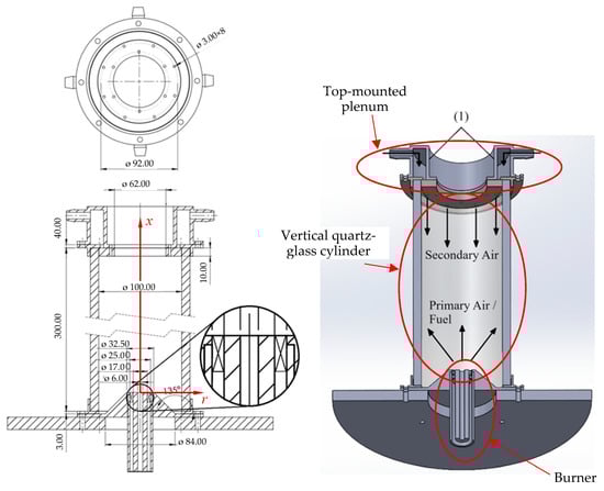
Figure 1.
Schematic of the combustion chamber.
2. Materials and Methods
2.1. Combustion Chamber
The combustion chamber investigated in the present work is shown in Figure 1. It is a vertical quartz-glass cylinder wrapped in a thick glass–fiber blanket to provide insulation. The inner diameter and the length of the chamber are equal to 100 mm and 300 mm, respectively. The thickness of the wall of the cylinder is 10 mm, and the insulation is 30 mm thick. The burner features a central tube, coaxial with the cylindrical chamber, surrounded by an annular swirler with vanes inclined at 45° to the axial direction. The burner head is elevated, positioned inside the chamber at a height of 25.8 mm above the base, resting atop a truncated cone.
The chamber is designed for both primary and secondary air injections. Primary air enters through the central tube of the burner and secondary air is supplied via a top-mounted plenum. This plenum contains eight holes, each 3 mm in diameter, positioned 2 mm from the chamber’s inner wall, as illustrated in Figure 1. During operation, primary air and fuel are introduced through the swirler and the central tube of the burner, respectively. The fuel is a mixture of natural gas and hydrogen. The properties of methane (the main component of natural gas) and hydrogen relevant to the present work are listed in Table 1.

Table 1.
Physical properties of hydrogen and methane at 300 K and 1 atm.
Limited experimental data are available for this combustor chamber. After ignition, the chamber operated for 1 h to achieve stable conditions and minimize transient heat losses before measurements were conducted. The thermal input (5 kW) was maintained unchanged during the experiments. The measurements of temperature and species concentration were conducted using probes mounted on a movable arm, inserted through the exit section of the chamber. Local mean temperatures were recorded using 76 μm diameter fine-wire platinum/platinum-13% rhodium (type R) thermocouples. Gas concentrations of O2, CO2, CO, and NO were measured using a stainless-steel, water-cooled probe. The gas species data exhibited high repeatability, with an average standard deviation of 5% from the mean. The experimental setup, the temperature measuring system, and the gas sampling system are identical to those described in Pacheco et al. [36]. Further details on the measurement procedures can be found in Silva [37].
2.2. Mathematical and Physical Models
2.2.1. Governing Equations
The mathematical model is based on the numerical solution of the Favre-averaged conservation equations for mass, momentum, energy, and mass fractions of chemical species, which may be written as follows for steady state conditions [38]:
where the overbar denotes a time-averaged value and the tilde denotes a density-weighted average value, while the double prime identifies a fluctuation about the density-weighted averaged value. In these equations, uj and xj are the velocity component and the coordinate in the jth direction, respectively, h is the specific enthalpy (sum of sensible and chemical enthalpy), yi the mass fraction of species i, p the pressure, ρ the density, μ the dynamic viscosity, λ the thermal conductivity, cp the specific heat capacity, Lei the Lewis number of species i, gi the component of the gravity vector in the ith direction, the radiative heat source, and the volumetric reaction rate of species i. These equations are based on the assumptions that the fluid is Newtonian, mass diffusion is governed by Fick’s law, the Dufour effect is negligible, and the mixture behaves as an ideal gas. The second term on the right side of Equation (3) is usually neglected. Similarly, the third and fourth terms on the right side of Equation (3), which account for viscous dissipation, are negligible, except in high Mach number flows. Furthermore, the second term into the square brackets in Equation (3) is also often neglected, assuming that the Lewis number is equal to unity for all species. The laminar diffusive fluxes of enthalpy and species may be modelled as [38]:
The Reynolds stresses, the enthalpy turbulent fluxes and the species turbulent fluxes (last term into parenthesis in Equations (2), (3), and (4), respectively) are calculated using a turbulence model. The mean reaction rate in Equation (4) and the radiative heat source in Equation (3) are modelled according to the combustion model and the radiation model, respectively. These models are summarized below.
2.2.2. Turbulence Model
The realizable k-ε model [39] was used in the present work. It has often been used in the simulation of turbulent flames in swirling burners, e.g., [40,41,42]. According to this model, the Reynolds stresses and the turbulent scalar fluxes are approximated as follows:
where k is the turbulent kinetic energy, ϕ is the scalar under consideration ( or ), and σϕ is the turbulent Prandtl or Schmidt number, which was set to 0.7. The turbulent viscosity is given by
where ε is the dissipation rate of turbulent kinetic energy. The model requires the solution of the following transport equations for k and ε [39]:
where S is the strain rate, Gb is the production of turbulent kinetic energy due to buoyancy, σκ, σε, and are constants of the model (σκ = 1.0, σε = 1.2, = 1.9, and = 1.0), is a dynamically computed parameter, and is a damping function.
2.2.3. Combustion Model
The eddy dissipation concept (EDC) [43] was selected for combustion modelling. It requires the solution of the transport equations for the species mass fractions. The EDC model is based on the detailed description of dissipation of the turbulent eddies. The flow is divided into two regions, namely the region that contains the small scales of turbulence, called the region of fine structures of the turbulence, and the region surrounding it. The model assumes that chemical reactions occur only in the region of fine turbulence structures, where all the turbulent kinetic energy is dissipated into heat. The fine structures of turbulence are considered small chemical reactors, and it is assumed that the reaction rate is equal to the rate of mass transfer of species between the fine turbulence structures and their surroundings.
The source term of the transport equation for the ith species, which represents the rate of mass production/consumption of that species per unit volume, [kg/m3·s], is given by [44]:
where γ* is the ratio of the mass in the fine structures to the total mass, χ the reacting fraction of fine structures, the fine-structure ith species mass fraction after reacting over the time scale τ*, the mass fraction of species i in the surroundings of the fine structures, and the mean mass fraction of species i. The time scale is defined as follows [44]:
where Cτ is a constant of the model, taken as 0.4083, and ν is the kinematic viscosity. Different definitions of γ* and χ have been proposed in the literature. In this work, a constant value of unity was used for χ, as proposed by Gran and Magnussen [45], and γ* was defined as [44]:
where is the mass of fine-structure regions divided by total mass, which is computed as
The volume fraction constant, , is equal to 2.1377.
An operator splitting algorithm was used in every iteration to determine the species mass fractions. In the first step, the fine-structure species mass fractions were calculated by solving a system of ordinary differential equations for a constant pressure chemical reactor using the stiff CVODE ordinary differential equations solver [46]. A clustering technique was used to accelerate the chemistry calculations. This technique joins together control volumes with similar chemical compositions, integrates the reduced set of equations, and then interpolates the clusters back to the control volumes. The computed values of the species mass fractions in the fine structures at t = τ* are used in Equation (12) to determine the mean reaction rates, which are required to solve the transport equations for the mean species mass fractions in the second step of the operator splitting algorithm.
The DRM-19 reaction mechanism [47] was used to describe the combustion of NG/H2 mixtures. This is a reduced mechanism based on Gri-Mech 1.2, an earlier version of Gri-Mech 3.0 [48], comprising 21 species and 84 reactions. The DRM-19 mechanism was also used by other authors to model NG/H2 flames, e.g., [49]. A test case was run using both DRM-19 and Gri-Mech 3.0. Since it was found that the results were quite close to each other and the DRM-19 mechanism requires fewer computational resources, it was selected for the present work. Since the NO chemistry is not included in this mechanism, a transport equation for the mass fraction of NO is solved, with the thermal NO production modelled using the extended Zeldovich mechanism [50] and the prompt NO formation simulated according to De Soete [51].
2.2.4. Radiation Model
Radiation in an emitting-absorbing medium is governed by the following equation [52]:
where Iν is the spectral radiation intensity at location r and along s direction, is the Planck function, κν is the spectral absorption coefficient, s is the coordinate along the direction of propagation of radiation, and subscripts ν and b denote wave number and black body, respectively. The integration of Equation (16) over all directions (solid angle of 4π) yields the radiative source term of the energy conservation equation [52]:
where q is the total radiative heat flux vector, which is defined as
and G is the incident radiation given by
The angular discretization is performed using the level symmetric SN quadrature. The radiative properties of the medium are determined using the weighted-sum-of-grey gases (WSGG) model [53].
2.2.5. Boundary Conditions
The mass flow rates of air and fuel were specified at their respective inlets (see Table 2). The velocity direction at the swirler exit was aligned with the inclination angle of the swirling vanes. A turbulence intensity of 10% was assumed at the inlets. The combustor operates at atmospheric pressure and the inlet air and fuel temperatures were set to 300 K for all studied cases. The species mass fractions of the fuel at the inlet were determined according to the considered hydrogen content, assuming that the natural gas is entirely constituted by methane. A pressure outlet boundary condition with zero-gauge pressure was applied at the exit section.
Table 2.
Fuel and mass flow rates for the studied operating conditions.
The laws of the wall were used to define the boundary conditions at the walls for the velocity and energy equations. The size of the control volumes adjacent to the walls was chosen to guarantee that y+ marginally exceeds 30, so that the corresponding grid nodes lie in the logarithmic layer, allowing for the use of the wall functions. The temperature of the cylindrical wall, as well as the temperatures of the other surfaces facing the interior of the combustion chamber, was set to 900 °C, based on measurements acquired using a thermocouple embedded in the wall. The temperature of the annular surface at the burner exit, between the fuel tube and the annular swirler, was set to 300 K.
To optimize computational efficiency, the computational domain was restricted to a sector of 45° of the combustion chamber, taking advantage of the geometrical periodicity. Periodic boundary conditions were applied to the axial planes delimiting the computational domain.
2.3. Numerical Methods and Computational Details
The Simcenter Star CCM+ code [54], based on the finite-volume method, was used to solve the governing equations. The convective fluxes of these equations were determined using the second-order upwind scheme to calculate cell face values. The variable gradients were computed using a hybrid Gauss-least squares method and the gradient limiter proposed by Venkatakrishnan [55]. The SIMPLE algorithm was employed for pressure-velocity coupling, and the algebraic systems of discretized equations were solved using the algebraic multigrid linear solver. Under-relaxation factors of 0.7 and 0.3 were used for the momentum and pressure, respectively, 0.8 for the turbulent kinetic energy and its dissipation rate, and 1.0 for the energy and species mass fraction equations.
Three different meshes were tested, consisting of approximately 128, 300, and 700 thousand control volumes. This corresponds to a refinement ratio of r = 1.33, defined as the cubic root of the ratio of the number of control volumes between two successive grids.
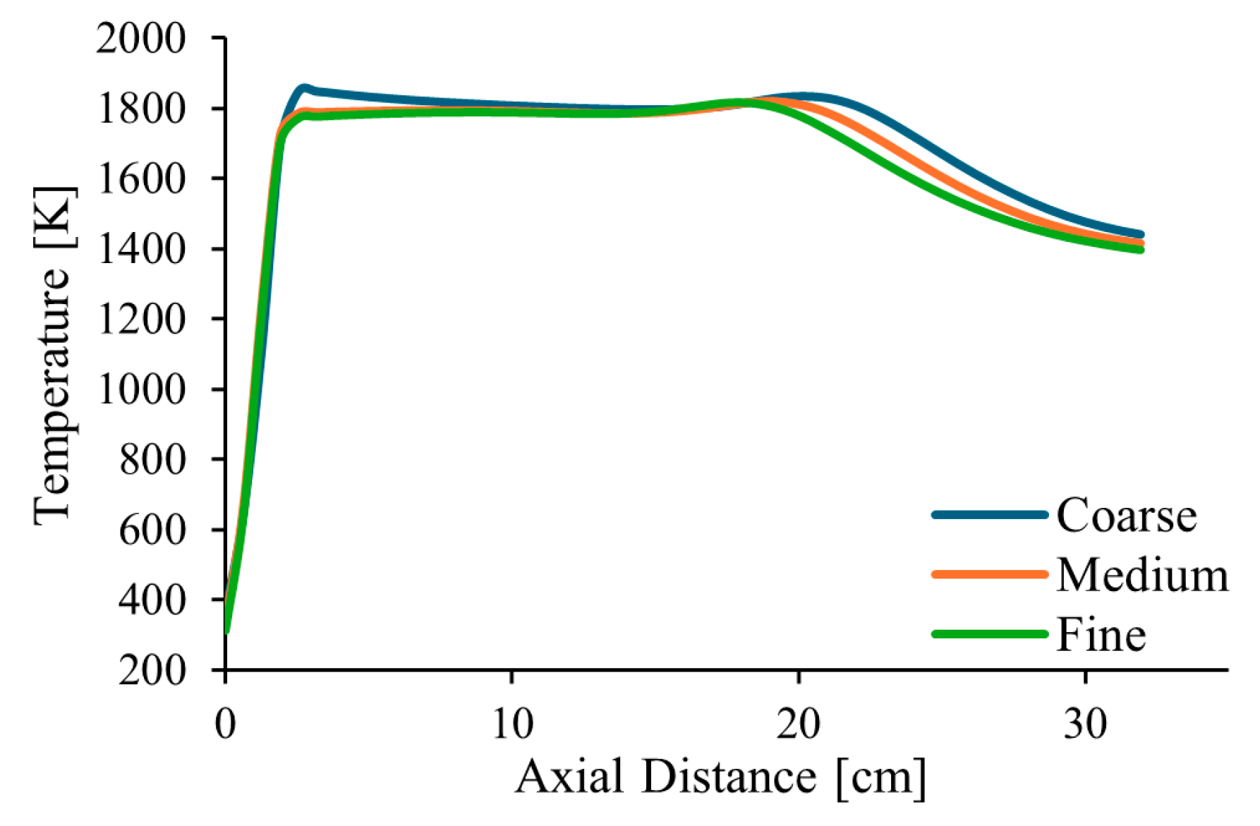
Figure 2 shows the temperature profiles along the centreline of the combustor and along a radial profile at the exit, in the middle axial plane of the computational domain, for pure natural gas, λ = 1.7 and α = 50%. The estimated order of convergence was found to be p = 1.77 and p = 1.84 for two points along the centreline, at distances of 210 and 345 mm from the burner exit, respectively. These values are a little lower than the theoretical value of p = 2, which is expected for a second-order spatial discretization scheme. This deviation is not surprising, as the actual order of convergence is influenced by factors such as grid quality and the non-linearities of the governing equations.
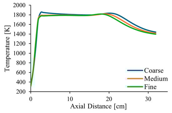
Figure 2.
Influence of the grid size on the axial temperature profile.
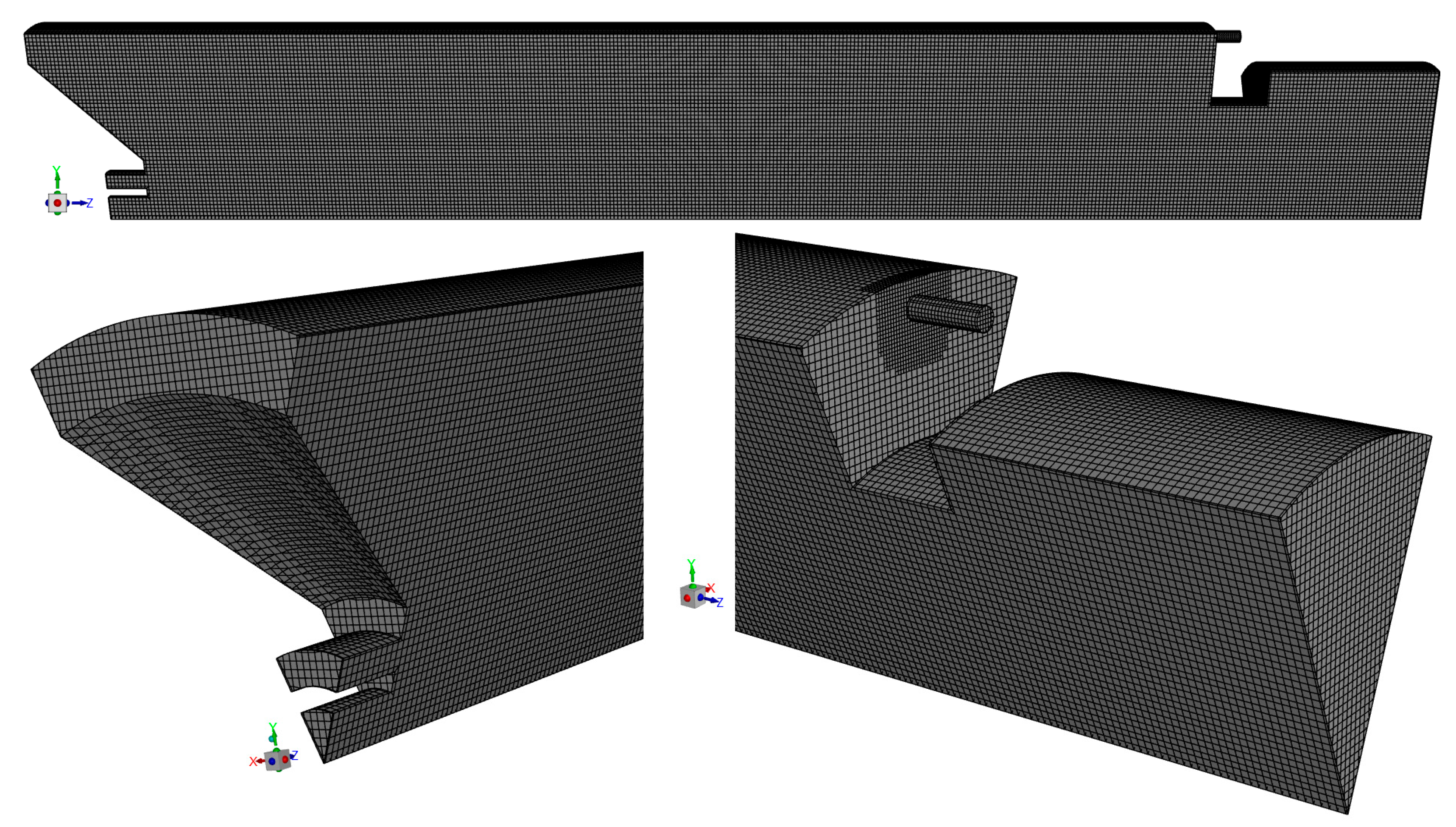
Additionally, the Grid Convergence Index (GCI), as defined by Roache [56], was calculated for the temperature at the two points mentioned above. The following results were obtained: GCI2,3 = 0.20% and GCI1,2 = 0.20% for the point closer to the burner and GCI2,3 = 3.43% and GCI1,2 = 2.05% for the other point, where subscripts 1, 2, and 3 denote the fine, medium, and coarse grids, respectively. These values are relatively small, especially the former ones, revealing that the solution is weakly sensitive to the grid size. The ratio GCI2,3/(rp GCI1,2) was found to be very close to unity, namely 0.999 for one point and 0.989 for the other. This indicates that the asymptotic range of convergence was reached. Based on these results, the medium mesh, shown in Figure 3, was selected for the calculations presented in the remainder of this paper.
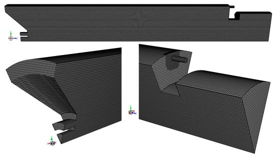
Figure 3.
Mesh used in the discretization of the computational domain.
3. Results and Discussion
3.1. Temperature and Velocity Fields
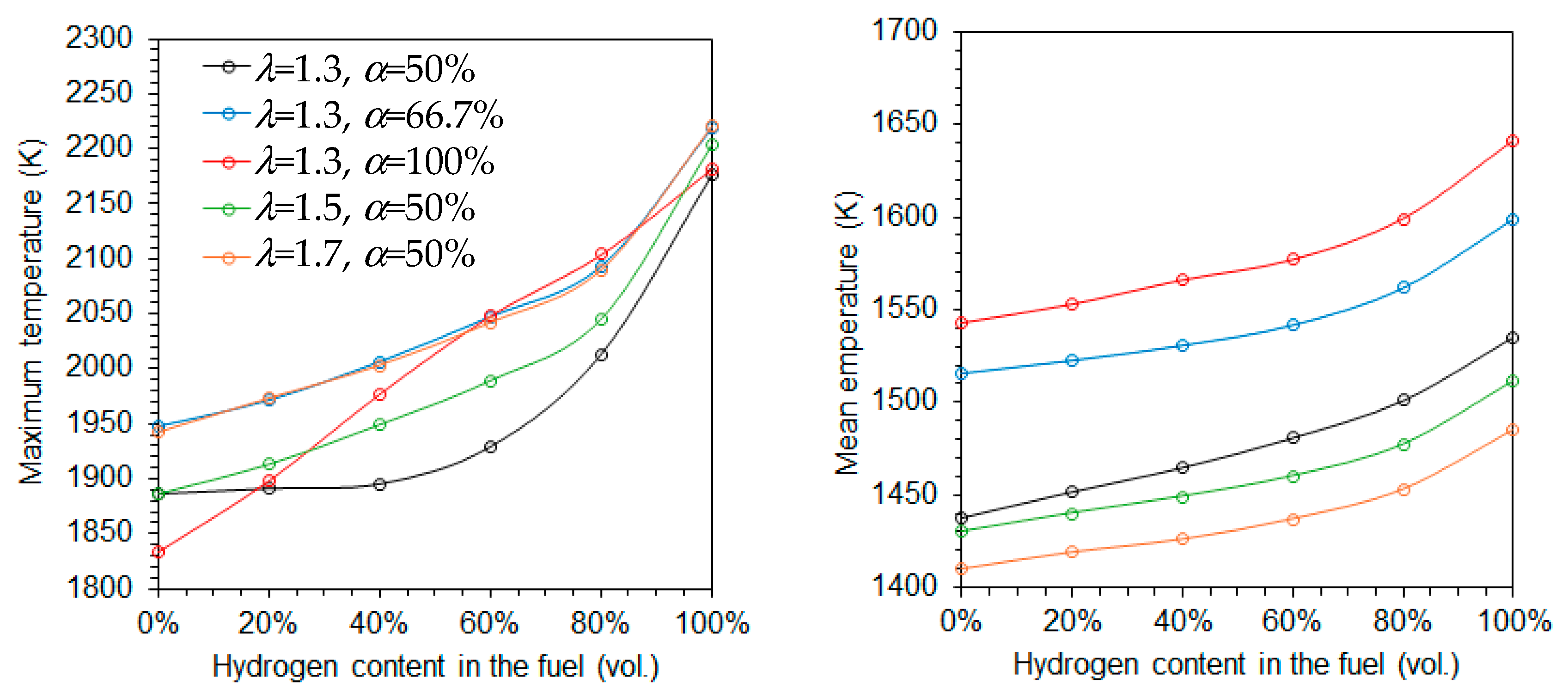
Figure 4 shows the variation of the maximum and average temperatures as a function of the hydrogen content in the fuel for five different combinations of the excess air coefficient (λ) and fraction of primary air (α). Both temperatures increase with rising hydrogen content, regardless of the specific values of λ and α. This trend is primarily attributed to the higher adiabatic flame temperature of hydrogen compared to natural gas. The increase is more significant for the maximum temperature than for the average temperature, especially at higher hydrogen content. However, when combustion is conducted using only primary air, the maximum temperature increases approximately linearly with the hydrogen molar fraction.
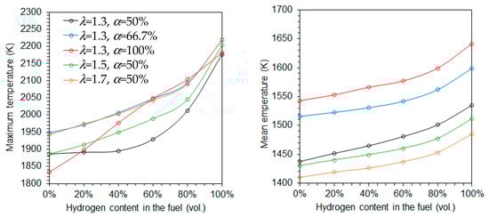
Figure 4.
Maximum (left side) and mean (right) temperatures as a function of the hydrogen content in the fuel.
The average temperature decreases with increasing excess air coefficients at a fixed α = 50%, as expected, due to the dilution effect of the excess air, as illustrated in Figure 4. However, the maximum temperature exhibits an opposite trend. This reversal is linked to the fact that combustion takes place under fuel-rich conditions in the reaction zone downstream of the burner. As the global equivalence ratio increases, the equivalence ratio based solely on the primary air approaches unity, enhancing combustion intensity in that zone, as discussed later.
When the excess air coefficient is held constant at 1.3, both the average and maximum temperatures increase with the fraction of primary air as α increases from 50% to 66.7%. This is because the combustion in the primary zone occurs closer to stoichiometric conditions at α = 66.7% than at α = 50%. When only primary air is used, i.e., α = 100%, the average temperature continues to rise, while the maximum temperature retains a near-linear dependence on the hydrogen molar fraction, as previously observed.
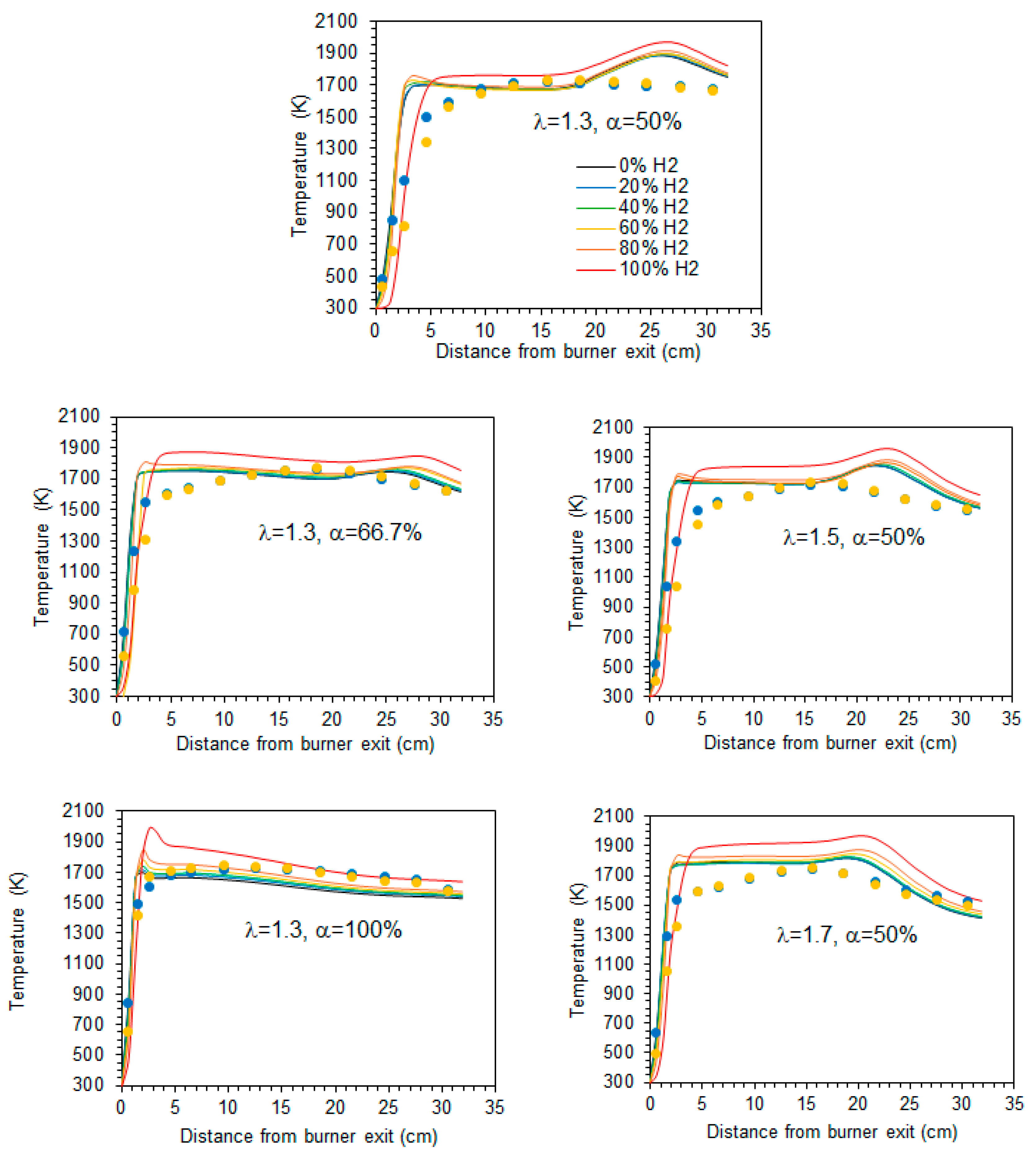
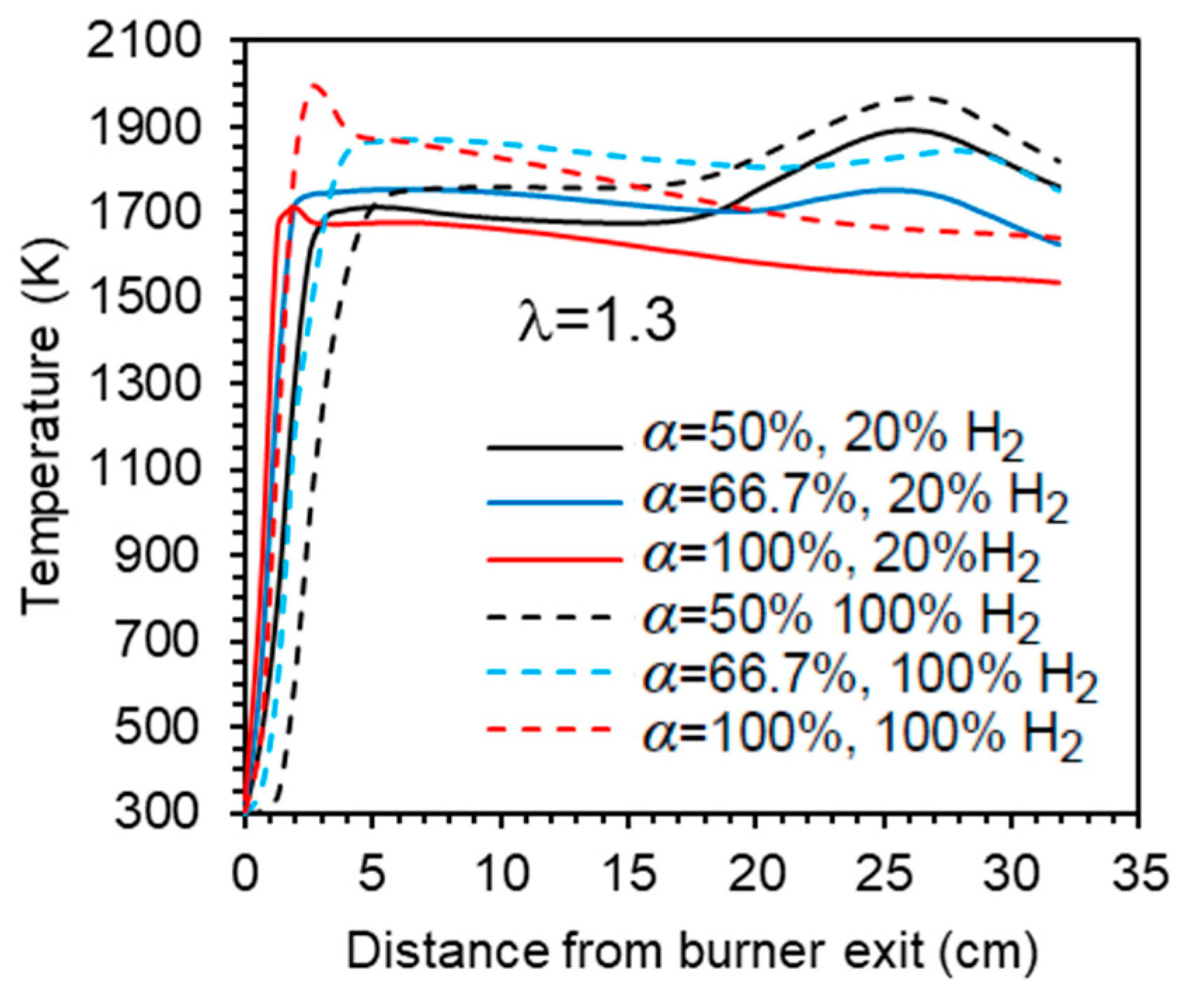
The mean temperature along the centreline of the combustor is shown in Figure 5 for a hydrogen content in the fuel ranging from 0% to 100% (by volume) and for the studied combinations of λ and α. A comparison of the various profiles reveals that there is a marginal temperature increase when the hydrogen content in the fuel rises from 0% to 80% (vol.). In the case of pure hydrogen, the increase of temperature at the burner exit occurs a little further downstream, and the temperature remains from 50 to 80 K higher than for the other fuel mixtures. Overall, while the temperature profiles for fuels with up to 80% H2 are relatively close to each other, the pure hydrogen flame temperature profile is clearly distinguishable from those, regardless of the excess air coefficient and fraction of primary air. This general observation is consistent with the findings of Gee et al. [25] and Daurer et al. [19]. Both studies investigated turbulent non-premixed NG/H2 flames in scaled industrial low-swirl, considering unconfined flames in the former study and confined flames in the latter one. Gee et al. found minimal visual differences for volumetric hydrogen contents of 10% and 30% (vol.), with only slight reductions in visible flame length, while Daurer et al. observed that the overall flame change remained largely unchanged up to 50% (vol.) hydrogen molar fraction, but a pure hydrogen flame exhibited different characteristics. However, the burner design flame, the combustion system configuration, the operating conditions, and the studied conditions (e.g., constant thermal input, constant volumetric fuel flow rate, constant Reynold number, etc.) vary widely in the literature, and other authors have reported changes in flame shape or length even for relatively small hydrogen molar fractions. Several authors observed a shorter flame and a shift of the temperature peak and reaction zone towards the burner as the hydrogen content in the fuel increased [11,15,18,21].

Figure 5.
Temperature profiles along the centreline. Blue and yellow symbols denote experimental data [37] for 20% and 60% H2 (vol.) in the fuel, respectively.
The axial profiles displayed in Figure 5 show a sharp temperature increase near the burner exit. Further downstream, the temperature remains nearly constant up to x ≈ 20 cm before rising again to reach a peak in case α = 50%, after which it decreases towards the exit section of the combustor. That peak is attenuated for α = 66.7% and does not occur for α = 100%, i.e., when there is no secondary air. In the latter case, the peak temperature occurs close to the burner. The higher temperatures observed for hydrogen flames in comparison to blended mixtures of hydrogen and natural gas have also been observed in many previous studies, e.g., [10,16,18,19]. This is due to the increase of the adiabatic flame temperature when the hydrogen content in the fuel rises. However, this increase is relatively small for low hydrogen content and only becomes larger when it approaches 100%, which explains the differences in the temperature profiles between the NG/H2 blends and the hydrogen flame.
In the present work, the thermal load was maintained constant. Therefore, for fixed values of λ and α, an increase in the hydrogen content in the fuel leads to a higher lower heating value (LHV) on a mass basis, resulting in a reduction of the fuel mass flow rate. Notably, the LHV of a mixture containing 20% NG and 80% H2 (vol.) is approximately 40% higher than that of a pure natural gas flame. In comparison, the LHV on a mass basis of a pure H2 flame is almost 150% higher than that of a natural gas flame [57], and so the fuel mass flow rate in the latter case is about 150% higher in comparison to the former one. Hydrogen has a molar weight and density that are both approximately one-eighth of those of methane, the primary component of natural gas. The mass flow rate of air decreases, similarly to the fuel mass flow rate, as the molar fraction of hydrogen increases, provided that λ remains constant. Therefore, the amount of nitrogen is reduced due to the lower air mass flow rate, further contributing to the temperature rise as the hydrogen fraction increases, as pointed out by Daurer et al. [19].
Experimental data [37] for hydrogen molar fractions of 20% and 60% are also presented in Figure 5. The predictions accurately capture the temperature rise downstream of the burner. However, the maximum temperature is overestimated and exhibits a sharp, nearly right-angled profile, in contrast to the smoother profile experimentally observed. Moreover, the measured temperature reaches a peak upstream of the numerically predicted maximum at x ≈ 20 cm, and the measured profile is smoother than the computational one.
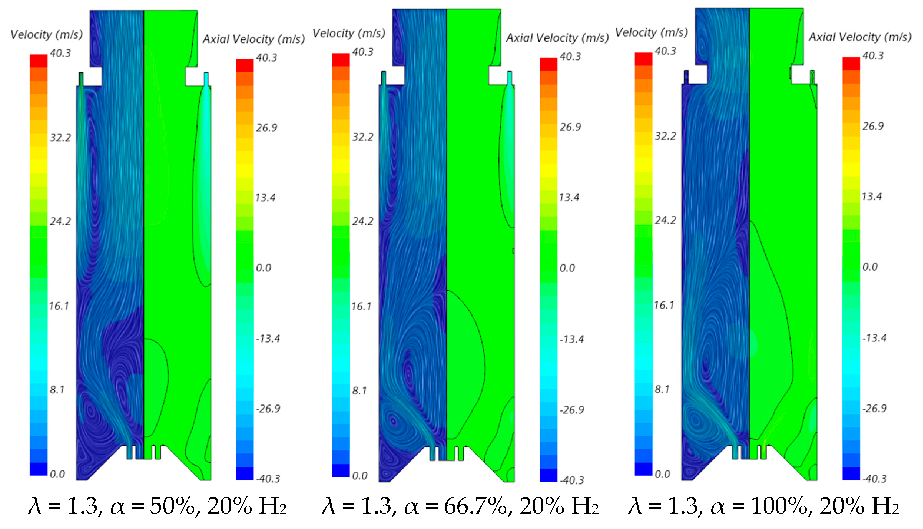
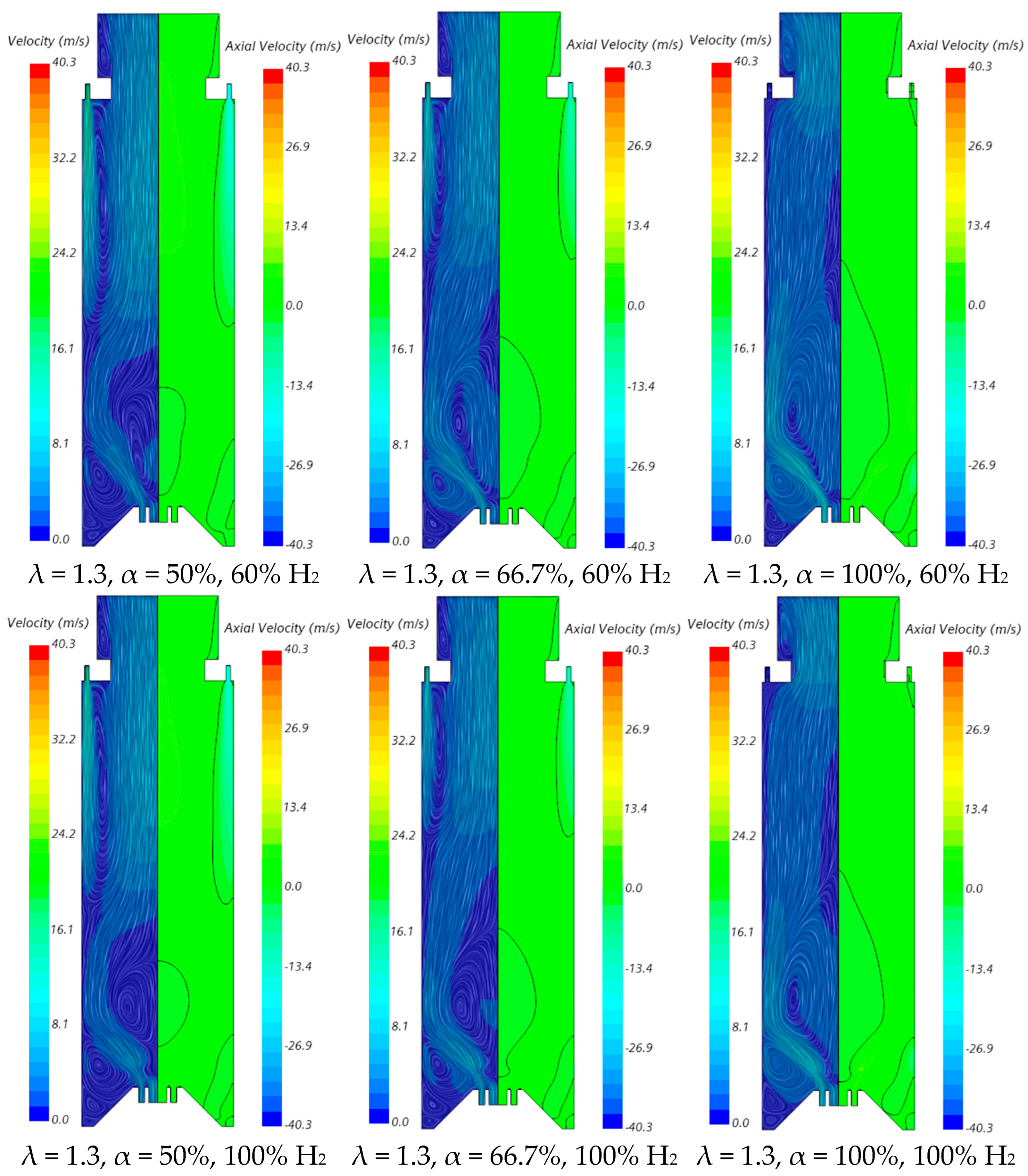
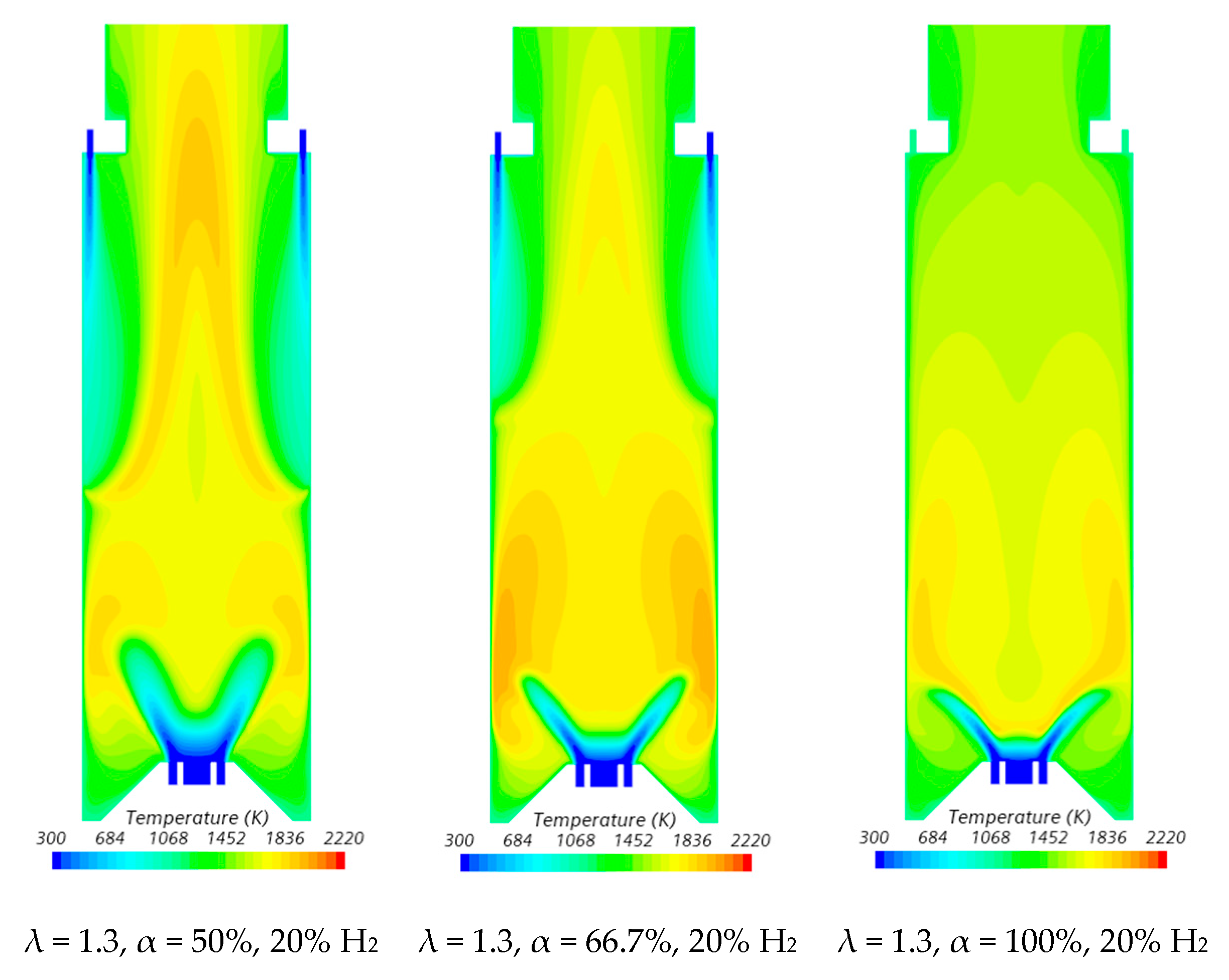
The velocity field and temperature contours in an axial plane passing through the centre of a secondary air injection hole are presented in Figure 6 and Figure 7, respectively, for λ = 1.3. Figure 6 indicates that the momentum of the secondary air jets for α = 50% or 66.7% is not sufficiently high to allow that air to reach the reaction zone near the burner. When α = 50%, the secondary air jets penetrate roughly up to one half of the chamber length, while for α = 66.7%, the penetration is reduced to about 1/3 of that length, regardless of the hydrogen content in the fuel. There is a slight decrease in the size of the central recirculation zone downstream of the burner, induced by the swirler, for pure hydrogen flames compared to NG/H2 flames. This aligns with the findings reported by several authors regarding the shrinkage of the reaction zone in the former case, as mentioned above. The flow pattern for α = 100% is different from that for α = 50% or 66.7%, since there is only primary air. The central recirculation zone is larger, and a small recirculation zone develops underneath the top-mounted plenum.
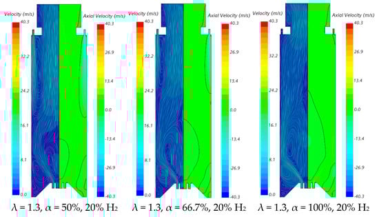
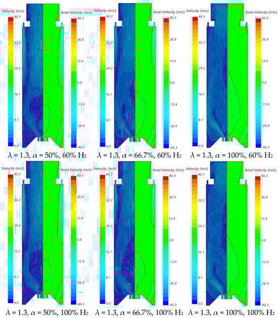
Figure 6.
Influence of the primary air fraction and hydrogen content in the fuel on the velocity field.
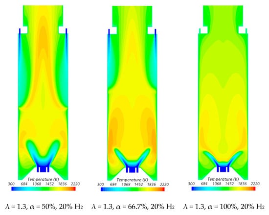
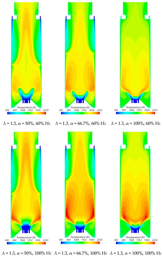
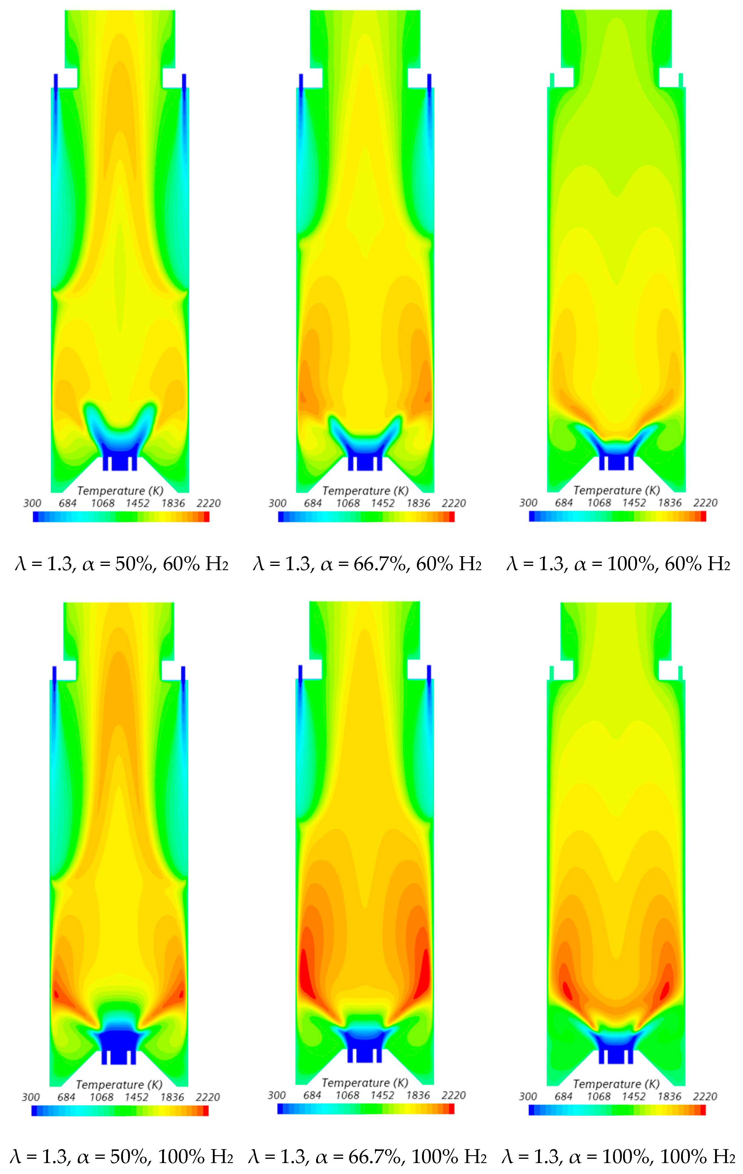
Figure 7.
Influence of the primary air fraction and hydrogen content in the fuel on the temperature field.
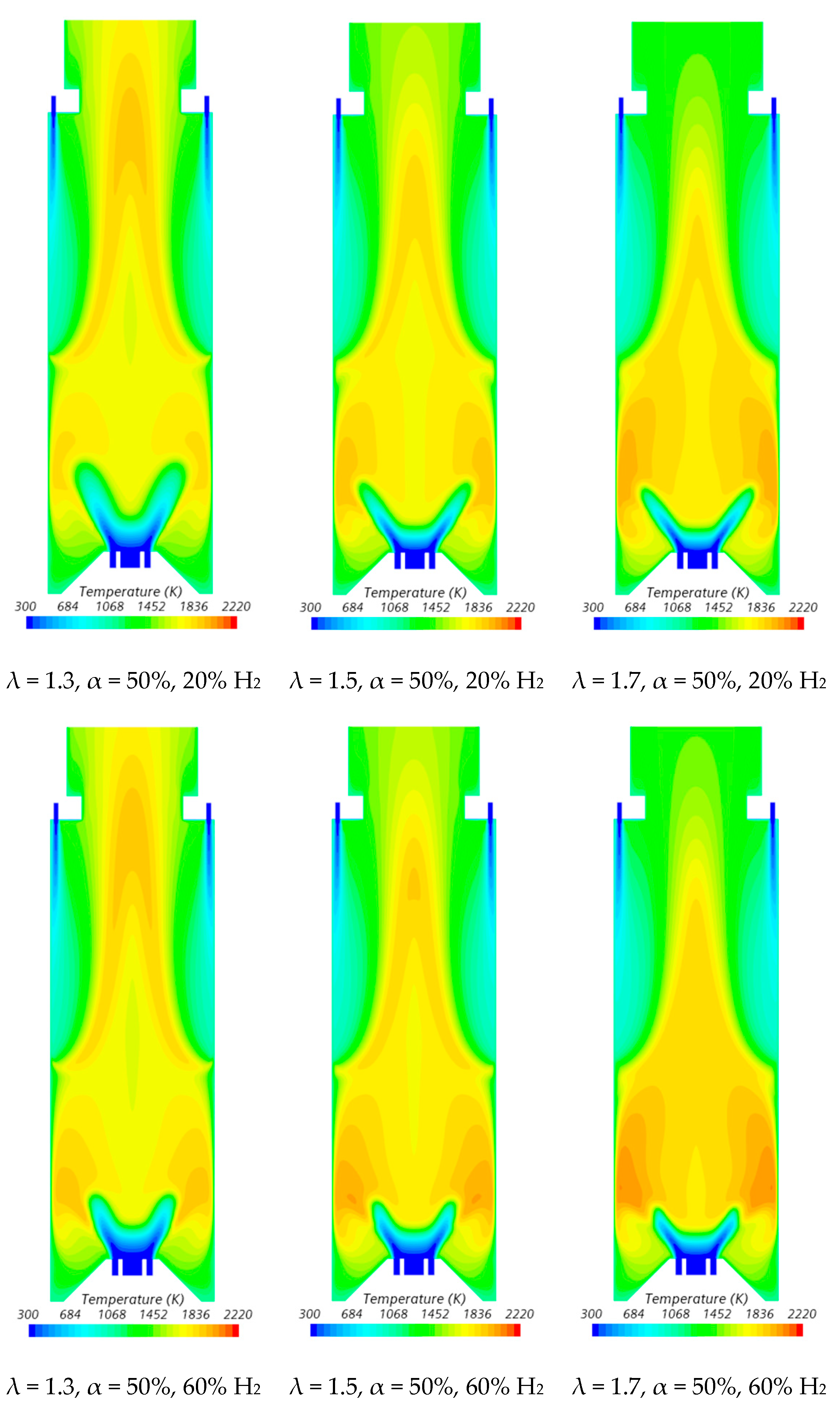
In the region between the inner shear layer (separating the main swirling flow and the central recirculation zone) and the outer shear layer (separating the main recirculation flow and the outer recirculation zone), the temperature is higher for hydrogen flames compared to blended NG/H2 flames, as illustrated in Figure 7. For α = 50%, the primary air supply is insufficient to achieve complete combustion, resulting in locally fuel-rich conditions near the burner and lower temperatures in the reaction zone. The secondary air jet mixes with recirculated combustion products and, after losing momentum, entrains the upward flow of the fuel-rich mixture, which contains unburned fuel and combustion products transported from the primary reaction zone. This leads to a temperature increase due to the combustion of the remaining unburned fuel at the mixing layer between the upward flow and the mixture of secondary air and recirculated combustion products.
The contraction of the horizontal cross-section, caused by the top mounted plenum, results in a peak temperature in the centreline at x ≈ 25 cm, as previously observed in Figure 5, particularly for α = 50%. These characteristics of the temperature field are also observed for the pure hydrogen flame, even though the temperatures are higher in this case. The inlet fuel and air velocities are also higher for hydrogen flames because the decrease in density, as the hydrogen content in the fuel increases, outweighs the reduction in mass flow rate. The higher velocities contribute to a reduction in the size of the central recirculation zone (see Figure 6) and a downstream shift in the initial temperature rise, despite the greater reactivity of hydrogen compared to natural gas.
The temperature field is not uniform at the exit section, suggesting that the combustion chamber may be slightly too short, potentially leading to incomplete combustion. For α = 66.7%, combustion near the burner still occurs under fuel-rich conditions but with a lower equivalence ratio. This results in higher local temperatures while reducing the amount of unburned fuel available for reactions further downstream, where temperatures are lower compared to α = 50%. When all the air is introduced through the swirler (α = 100%), combustion is concentrated near the burner, leading to more complete fuel consumption in this region. As a result, the temperature distribution becomes more uniform further downstream.
The influence of the primary air fraction on the temperature profile along the centreline is further illustrated in Figure 8 for λ = 1.3. In the case of α = 66.7%, the mixture remains fuel-rich in the reaction zone near the burner, but the temperature profiles are smoother compared to α = 50%. Higher temperatures are reached in the central recirculation zone, while the peak temperature at x ≈ 25 cm is significantly reduced. When α = 100%, a single peak temperature occurs near the burner, followed by a gradual decrease further downstream towards the exit section.
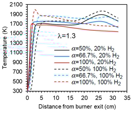
Figure 8.
Influence of the primary air fraction and hydrogen content in the fuel on the axial temperature profile.
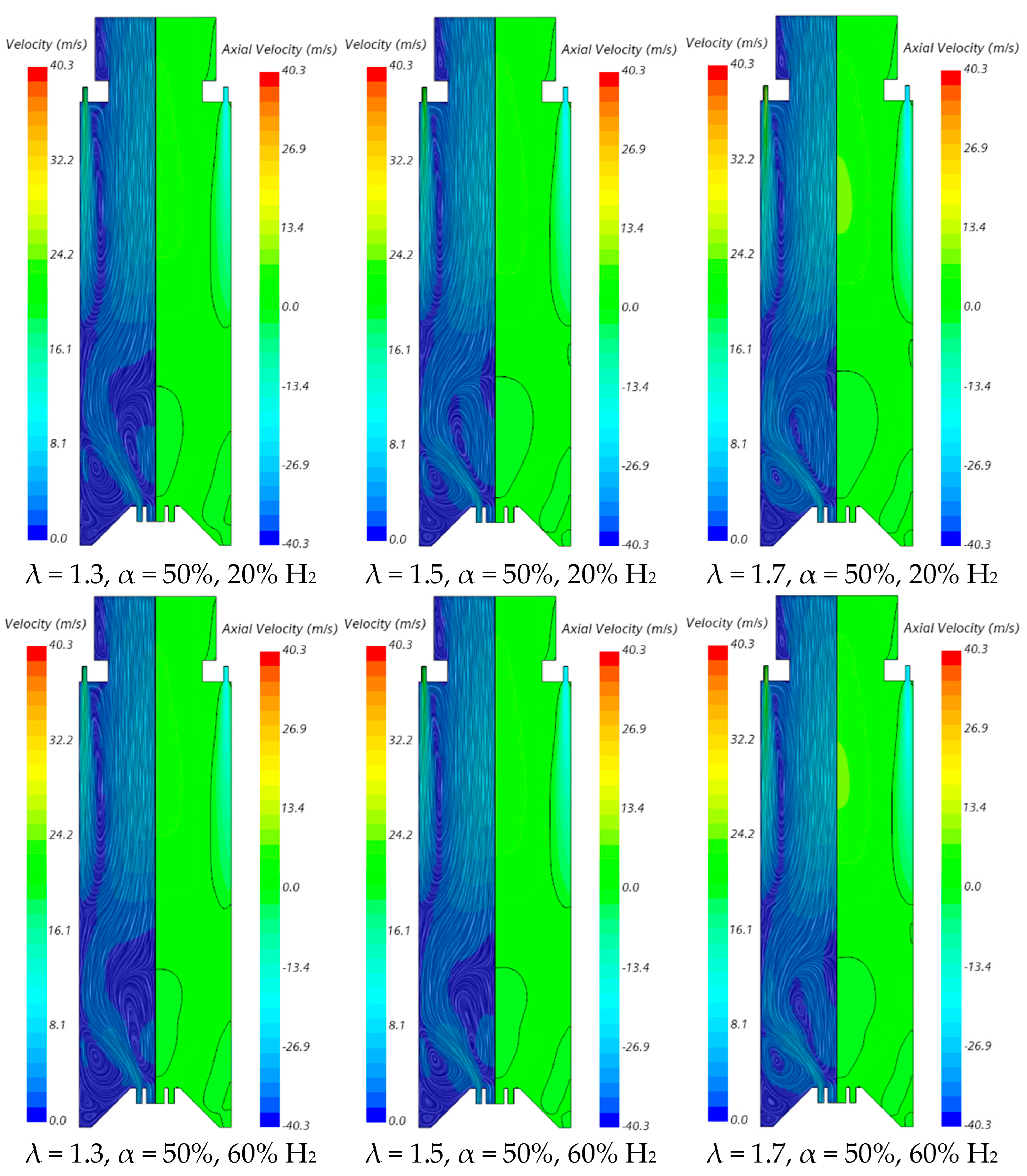
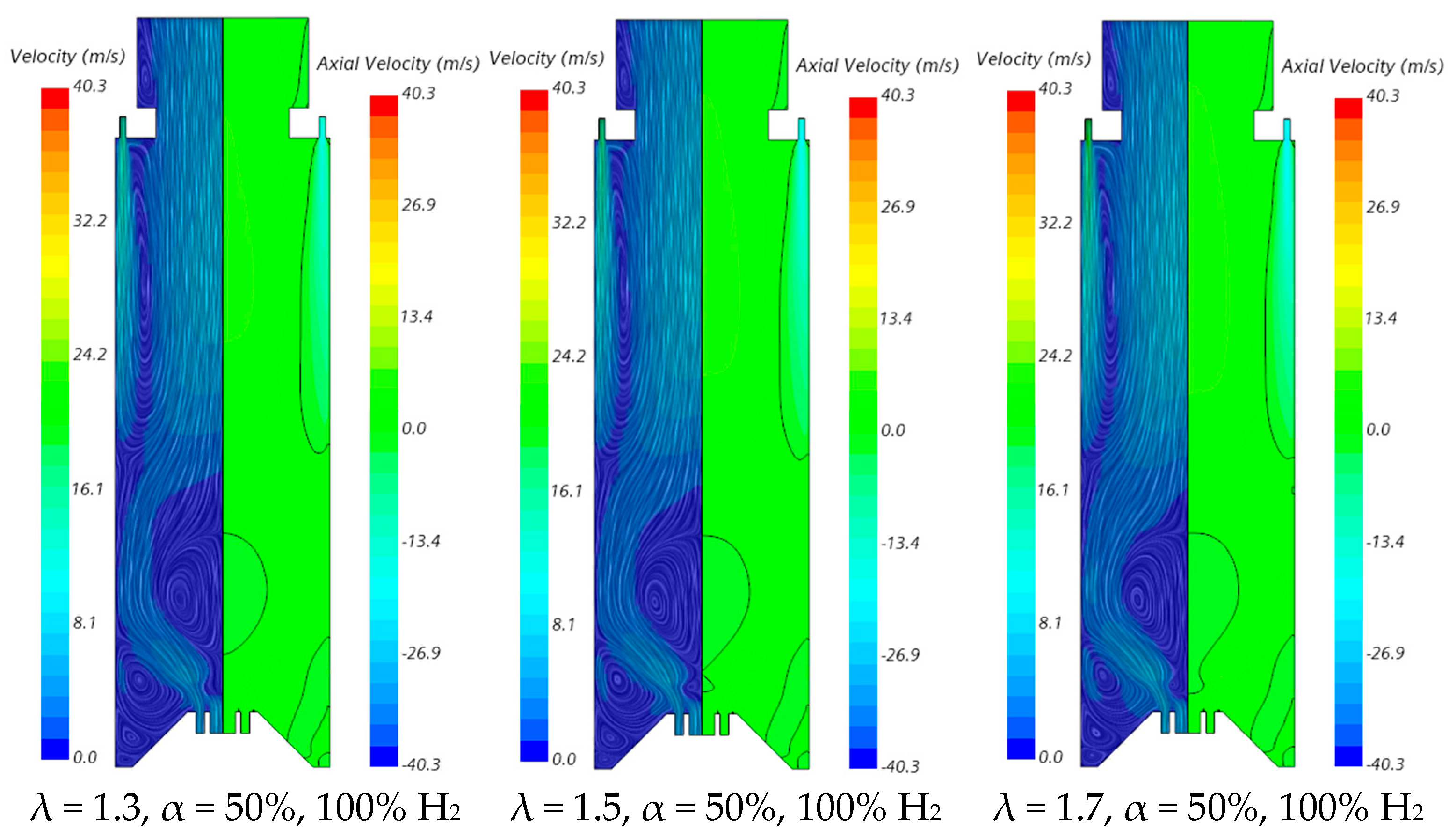
The influence of the excess air coefficient on the velocity field and temperature contours in an axial plane passing through the centre of a secondary air injection hole is illustrated in Figure 9 and Figure 10, respectively, for α = 50%. The velocity field remains nearly unchanged with varying λ for a given fuel composition. However, a slight increase in the size of the central recirculation zone is observed as λ increases. This occurs due to the enhanced swirl intensity with additional air, which strengthens mixing and recirculation. An increase in the excess air coefficient leads to higher temperatures in the region between the inner and outer shear layers of the swirling flow. This is because, for α = 50%, combustion near the burner occurs under fuel-rich conditions, and the local equivalence ratio, based only on the primary air and fuel, approaches unity as λ increases from 1.3 to 1.7, raising the adiabatic flame temperature. In addition, as λ increases, the amount of unburned fuel leaving the reaction zone near the burner decreases. Consequently, the reaction with secondary air occurring further downstream takes place under leaner conditions, leading to lower temperatures towards the exit section.
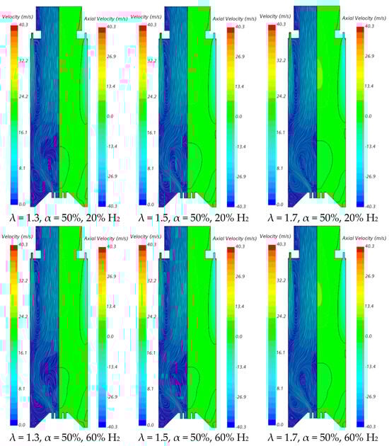
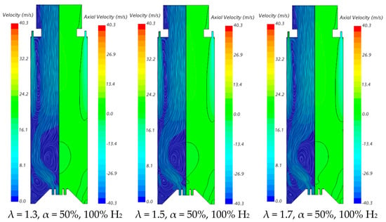
Figure 9.
Influence of the excess air coefficient and hydrogen content in the fuel on the velocity field.


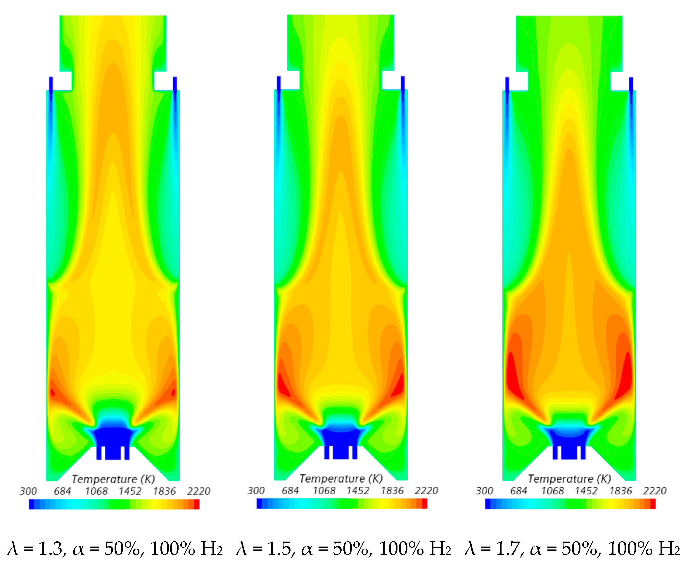
Figure 10.
Influence of the excess air coefficient and hydrogen content in the fuel on the temperature field.
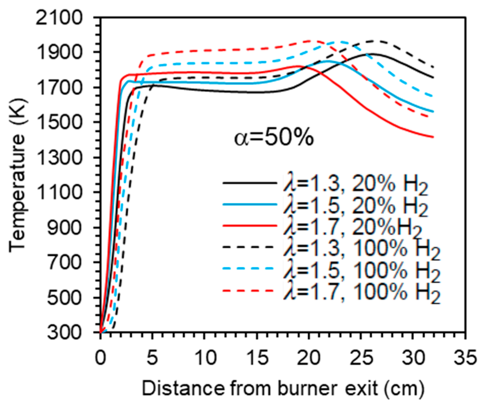
Figure 11 presents the centreline temperature profiles as a function of the excess air coefficient for α = 50%. As λ increases, the initial temperature rise shifts slightly to the burner. This occurs because the additional air enhances mixing, strengthening the reaction zone near the burner and raising the temperature. Further downstream, the temperature increases and reaches a peak for λ = 1.3 and λ = 1.5, as previously explained. However, the peak is less pronounced for λ = 1.5, occurs furthest from the exit, and nearly disappears for λ = 1.7. Beyond the peak, dilution effects cause the temperature to decrease towards the exit section.
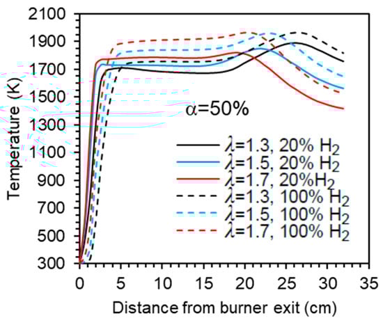
Figure 11.
Influence of the excess air coefficient and hydrogen content in the fuel on the axial temperature profile.
3.2. Emissions
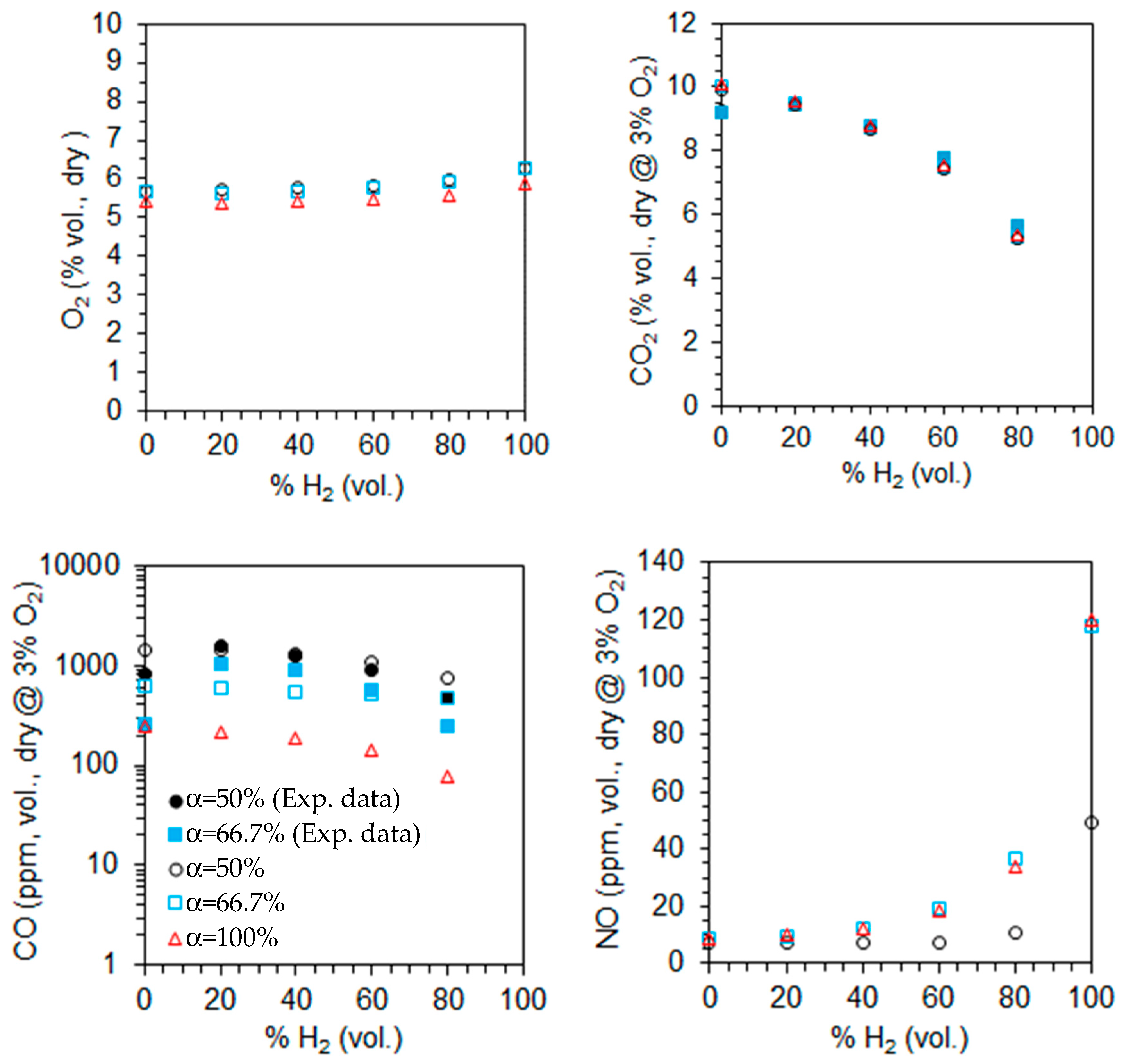
The computed emissions of O2, CO2, CO, and NO on a volumetric and dry basis are shown in Figure 12 for λ = 1.3 as a function of the primary air fraction and hydrogen content in the fuel. The measured CO and CO2 emissions for two different primary air fractions, α = 50% and α = 66.7%, are also plotted in Figure 12. The CO2, CO, and NO emissions are corrected to 3% O2. The O2 molar fraction increases slightly, while that of CO2 decreases with increasing hydrogen content in the fuel, as expected from a single step, global and complete chemical reaction. These trends become more pronounced for higher hydrogen content in the fuel. The O2 emissions are similar for α = 50% and 66.6% but slightly lower for α = 100%, suggesting incomplete combustion in the former cases. This is consistent with the high CO emissions observed for α = 50% and 66.6%, which can be attributed to the limited penetration of the secondary air jets. This restricted penetration reduces the residence time in the high-temperature oxidation zone and diminishes mixing efficiency, both of which are critical for the complete oxidation of CO.
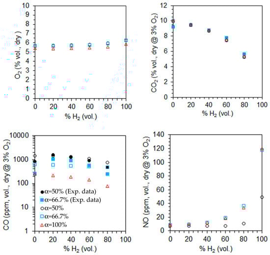
Figure 12.
Molar fractions of the species at the exit for λ = 1.3 as a function of the primary air fraction and hydrogen content in the fuel (open symbols—predictions, solid symbols—measurements).
The NO emissions are lowest for α = 50% and show little variation between α = 66.7% and α = 100%. For a given fuel composition, secondary air helps to reduce temperatures in the primary reaction zone, downstream of the burner, where most fuel is burned (see Figure 7 and Figure 9 for α = 100%). This temperature reduction leads to lower NO emissions, particularly for α = 50%. As the hydrogen molar fraction in the fuel increases from 0% to 80%, NO emissions rise, with a more pronounced increase for pure hydrogen flames. This trend is linked to temperature levels, which remain relatively low in the former case (see Figure 7 and Figure 9), significantly limiting NO formation via the thermal route. As a result, NO emissions are much lower than in pure hydrogen flames.
The reduction in CO emissions with increasing hydrogen content in the fuel has been reported by several authors, e.g., [18,58]. This reduction is primarily attributed to two factors: the lower amount of carbon in the fuel, which directly reduces CO formation, and the enhanced production of OH radicals due to the higher hydrogen content, which significantly accelerates CO oxidation.
In contrast, the NO emissions increase as the molar fraction of hydrogen in the fuel rises, and this trend is stronger when the molar fraction approaches the unity. As the hydrogen molar fraction increases, the adiabatic flame temperature rises, promoting NO formation through the thermal mechanism. Additionally, the increased concentration of O, H, and OH radicals with hydrogen enrichment further enhances NO production through the same pathway. As a result, in the absence of mitigating factors, an increase in NOx emissions is expected. This trend has been widely observed in both experimental and computational studies across various flame and burner configurations, as well as different combustion systems (see, e.g., [15,18,24]).
The predicted CO2 emissions for natural gas were underestimated compared to the experimental data, while those of CO were overpredicted. A reverse trend was observed for 60% and 80% H2, while accurate predictions were obtained for 20% and 40% H2 at α = 50%. The CO emissions were underestimated for 20% and 40% H2 at α = 66.7%. Several reasons may explain the discrepancies between the measurements and the predictions. However, since the physical phenomena (turbulence, combustion, chemical kinetics) are strongly coupled, and there are always experimental measurement uncertainties; especially in regions of steep gradients, it is not feasible to ascertain the main reason for the observed differences. These are most likely due to the combination of different sources of uncertainty.
The marginal impact or a slight increase of the CO emissions from 0% to 20% aligns with the findings of other authors. Rørtveit et al. [59] conducted experiments using four different burners while maintaining the thermal power and excess air coefficient unchanged. Their results indicated that, although CO emissions varied with the burner type, they were largely unaffected by hydrogen molar fractions between 0% and 30%. Similarly, Ge et al. [20], in experiments with a low dry emission burner, observed that CO emissions remained nearly unchanged, at constant thermal power, from 0% to 26% H2 (vol.).
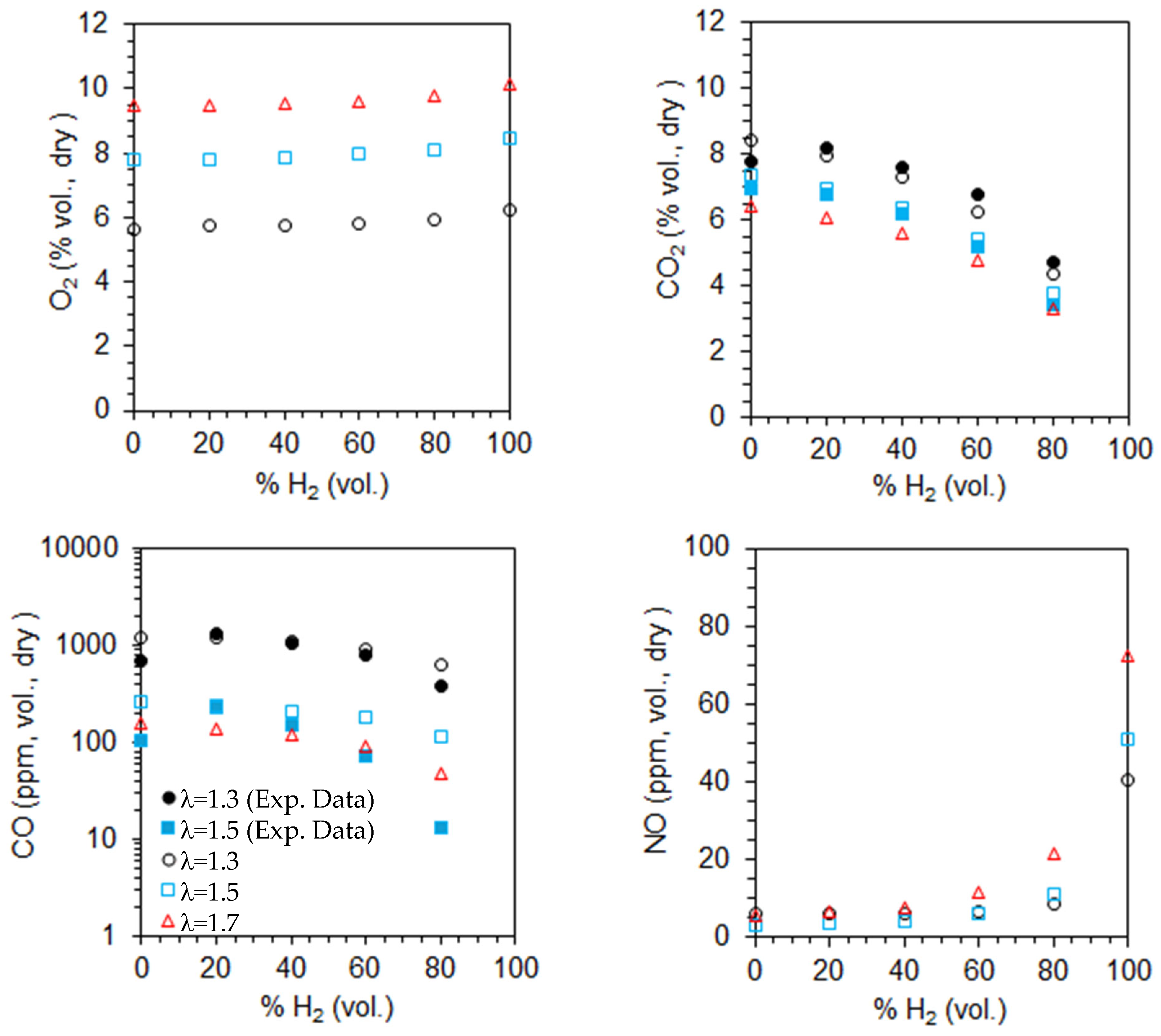
Figure 13 presents the computed emissions of O2, CO2, CO, and NO on a volumetric, dry basis for α = 50%, as a function of the excess air coefficient and hydrogen content in the fuel. The influence of the fuel composition on emissions was discussed earlier. For a given fuel composition, the O2 emissions increase as the excess air coefficient rises, while CO and CO2 emissions decrease, as expected. This occurs because a higher excess air coefficient provides more oxygen for fuel combustion, leading to lower CO emissions. Additionally, CO2 emissions decrease due to dilution effects. The CO emissions remain high for λ = 1.3 and 1.5, but they drop below 100 ppm when the hydrogen content in the fuel reaches 60% or more.
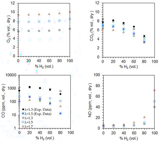
Figure 13.
Molar fractions of the species at the exit for α = 50% as a function of the excess air coefficient and hydrogen content in the fuel (open symbols—predictions, solid symbols—measurements).
NO emissions increase with the excess air coefficient for a given fuel composition, particularly at high hydrogen content. In fact, for α = 50%, the adiabatic flame temperature in the reaction zone near the burner, based on the local equivalence ratio, rises as λ increases from 1.3 to 1.7, as previously discussed. The higher temperatures, which can be observed in Figure 10, enhance thermal NO formation, resulting in increased NO emissions.
These results indicate that secondary air is particularly beneficial for pure hydrogen flames, as there are no CO emissions and NO emissions are relatively low despite an increase in NO emissions with a higher excess air coefficient. For NG/H2 mixtures, CO emissions are high and increase with the primary air fraction. However, this effect is mitigated by increasing the excess air coefficient. Thus, there is potential to optimize the combustor design to reduce CO emissions while using secondary air. Possible improvements include reducing the diameter of the secondary air injection holes to enhance the jet momentum and penetration and lengthening of the top-mounted plenum, and, consequently, the overall combustor length, to increase the residence time of secondary air, thereby allowing for complete fuel combustion. Additional NOx-reduction strategies, including exhaust gas recirculation, lean combustion, and MILD combustion, warrant further investigation.
The EDC model is based on the assumptions that the reaction rates are controlled by turbulence–chemistry interaction and reactions occur primarily in fine turbulence structures. Accordingly, the model may not capture the fast chemical kinetics of hydrogen combustion well and, therefore, the accuracy may decrease when the molar fraction of hydrogen in the fuel is high. This issue should be investigated in future work, even though the EDC model has been used by several authors to simulate hydrogen flames, e.g., [60,61].
4. Conclusions
A computational study was conducted on NG/H2 turbulent swirling flames in a novel combustion chamber, with the molar fraction of hydrogen varying from 0% to 100%. The key findings are:
- (i)
- The size of the central recirculation zone induced by the swirler slightly decreases for pure hydrogen flames compared to NG/H2 flames. Flow patterns vary depending on the presence of secondary air. When only primary air is used, the central recirculation zone is larger, and a smaller recirculation zone forms beneath the top-mounted plenum.
- (ii)
- The maximum and average temperatures in the combustor increase with rising hydrogen content in the fuel. At a fixed fuel composition and primary air fraction (α = 50%), the average temperature decreases while the maximum temperature increases with increasing excess air coefficient. When the excess air coefficient is held constant (λ = 1.3), both the average and maximum temperatures increase with the primary air fraction as α increases from 50% to 66.7%. At α = 100%, the average temperature continues to increase while the maximum temperature maintains a near-linear dependence on the hydrogen molar fraction.
- (iii)
- The temperature in the region delimited by the inner and outer shear layers of the swirling flow increases with the rise of the hydrogen content in the fuel. The temperature rise at the centreline shifts slightly downstream for pure hydrogen flames, and the temperature remains 50° to 80 °C higher than for blended CH4/H2 flames towards the exit section. When secondary air is introduced, the temperature decreases in the reaction zone, but a second temperature peak appears at the centreline, near the exit due to the combustion of unburned fuel transported from the primary reaction zone.
- (iv)
- Increasing the primary air fraction results in a smoother temperature profile along the centerline. When only primary air is used, the centerline profile exhibits a single temperature peak near the burner, followed by a gradual downstream decline. As the excess air coefficient increases, the initial rise in centerline temperature shifts slightly closer to the burner. Further downstream, a temperature peak appears for λ = 1.3 and λ = 1.5, though it is less pronounced at λ = 1.5 and nearly disappears at λ = 1.7. Beyond this peak, dilution effects dominate, leading to a temperature decrease towards the combustor exit.
- (v)
- The O2 and CO emissions are higher for α = 50% and 66.6% than for α = 100%, indicating incomplete combustion in the former case. The NO emissions are lowest for α = 50% and show little variation between α = 66.7% and α = 100%. They do not exceed 50 ppm, except for pure hydrogen combustion and α ≥ 66.7%. For a given fuel composition, CO2 and CO emissions decrease, while NO emissions increase with the excess air coefficient.
- (vi)
- The CO emissions decrease and NO emissions increase with rising hydrogen content in the fuel, a trend that becomes more pronounced as the hydrogen molar fraction approaches unity.
- (vii)
- Secondary air is particularly useful for hydrogen flames, as NO emissions remain relatively low (e.g., ~40 ppm at λ = 1.3 and α = 50%) despite increasing with higher excess air coefficients, and CO emissions are absent. For NG/H2 flames, secondary air is effective only at sufficiently high excess air levels to keep CO emissions within acceptable limits.
Author Contributions
Conceptualization, M.A.A.M. and P.J.C.; methodology, M.A.A.M. and P.J.C.; validation, B.M.P.; formal analysis, B.M.P.; investigation, B.M.P. and G.P.P.; resources, M.A.A.M. and P.J.C.; data curation, B.M.P.; writing—original draft preparation, P.J.C.; writing—review and editing, G.P.P., M.A.A.M. and P.J.C.; visualization, B.M.P.; supervision, M.A.A.M. and P.J.C.; project administration, P.J.C.; funding acquisition, P.J.C. All authors have read and agreed to the published version of the manuscript.
Funding
The authors acknowledge Fundação para a Ciência e a Tecnologia (FCT) for its financial support via the projects no. 2022.08675.PTDC (http://doi.org/10.54499/2022.08675.PTDC) and LAETA Base Funding (DOI: 10.54499/UIDB/50022/2020). Gonçalo Pacheco acknowledges FCT for the provision of Scholarship 2021.04674.BD.
Institutional Review Board Statement
Not applicable.
Informed Consent Statement
Not applicable.
Data Availability Statement
The data that support the findings of this study are available from the corresponding author upon reasonable request. The data are not publicly available due to privacy.
Conflicts of Interest
The authors declare no conflicts of interest.
References
- Ritchie, H.; Rosado, P. Energy Mix. Available online: https://ourworldindata.org/energy-mix (accessed on 18 November 2024).
- International Energy Agency. World Energy Outlook 2024. Available online: https://www.iea.org/reports/world-energy-outlook-2024 (accessed on 29 May 2024).
- Hassan, Q.; Viktor, P.; Al-Musawi, T.J.; Ali, B.M.; Algburi, S.; Alzoubi, H.M.; Al-Jiboory, A.K.; Sameen, A.Z.; Salman, H.M.; Jaszczur, M. The renewable energy role in the global energy Transformations. Renew. Energy Focus 2024, 48, 100545. [Google Scholar] [CrossRef]
- Mistry, A. The (annoyingly) slow pace of energy transition. MRS Bull. 2023, 48, 688–689. [Google Scholar] [CrossRef]
- Capurso, T.; Stefanizzi, M.; Torresi, M.; Camporeale, S.M. Perspective of the role of hydrogen in the 21st century energy transition. Energy Convers. Manag. 2022, 251, 114898. [Google Scholar] [CrossRef]
- Ishaq, H.; Dincer, I.; Crawford, C. A review on hydrogen production and utilization: Challenges and opportunities. Int. J. Hydrogen Energy 2022, 47, 26238–26264. [Google Scholar] [CrossRef]
- Xie, Z.; Jin, Q.; Su, G.; Lu, W. A review of hydrogen storage and transportation: Progresses and challenges. Energies 2024, 17, 4070. [Google Scholar] [CrossRef]
- Levinsky, H. Why can’t we just burn hydrogen? Challenges when changing fuels in an existing infrastructure. Prog. Energy Combust. Sci. 2021, 84, 100907. [Google Scholar] [CrossRef]
- Abdin, Z. Bridging the energy future: The role and potential of hydrogen co-firing with natural gas. J. Clean. Prod. 2024, 436, 140724. [Google Scholar] [CrossRef]
- Kim, H.S.; Arghode, V.K.; Gupta, K. Flame characteristics of hydrogen-enriched methane–air premixed swirling flames. Int. J. Hydrogen Energy 2009, 34, 1063–1073. [Google Scholar] [CrossRef]
- Kashir, B.; Tabejamaat, S.; Jalalatian, N. A numerical study on combustion characteristics of blended methane-hydrogen bluff-body stabilized swirl diffusion flames. Int. J. Hydrogen Energy 2015, 40, 6243–6258. [Google Scholar] [CrossRef]
- Wang, D.; Tan, Z.; Xu, J.; Meng, H. Quantitative studies of NO emissions from various reaction pathways in swirling combustion of hydrogen-enriched methane. Int. J. Hydrogen Energy 2024, 53, 409–421. [Google Scholar] [CrossRef]
- Du, W.; Zhou, S.; Qiu, H.; Zhao, J.; Fan, Y. Experiment and numerical study of the combustion behavior of hydrogen-blended natural gas in swirl burners. Case Stud. Therm. Eng. 2022, 39, 102468. [Google Scholar] [CrossRef]
- Elbayoumi, M.; Garnier, F.; Seers, P. Numerical study of the impact of hydrogen addition, swirl intensity and equivalence ratio on methane-air combustion. Int. J. Turbo Jet. Eng. 2024, 41, 377–393. [Google Scholar] [CrossRef]
- Cozzi, F.; Coghe, A. Behavior of hydrogen-enriched non-premixed swirled natural gas flames. Int. J. Hydrogen Energy 2006, 31, 669–677. [Google Scholar] [CrossRef]
- Kim, H.S.; Arghode, V.K.; Linck, M.B.; Gupta, A.K. Hydrogen addition effects in a confined swirl-stabilized methane-air flame. Int. J. Hydrogen Energy 2009, 34, 1054–1062. [Google Scholar] [CrossRef]
- Ilbas, M.; Yilmaz, I. Experimental analysis of the effects of hydrogen addition on methane combustion. Int. J. Energy Res. 2012, 36, 643–647. [Google Scholar] [CrossRef]
- Rajpara, P.; Shah, R.; Banerjee, J. Effect of hydrogen addition on combustion and emission characteristics of methane fueled upward swirl can combustor. Int. J. Hydrogen Energy 2018, 43, 17505–17519. [Google Scholar] [CrossRef]
- Daurer, G.; Schwarz, S.; Demuth, M.; Gaber, C.; Hochenauer, C. Experimental and numerical analysis of industrial-type low-swirl combustion of hydrogen enriched natural gas including OH* chemiluminescence imaging. Int. J. Hydrogen Energy 2024, 80, 890–906. [Google Scholar] [CrossRef]
- Ge, B.; Ji, Y.; Zhang, Z.; Zang, S.; Tian, Y.; Yu, H.; Chen, M.; Jiao, G.; Zhang, D. Experiment study on the combustion performance of hydrogen-enriched natural gas in a DLE burner. Int. J. Hydrogen Energy 2019, 44, 14023–14031. [Google Scholar] [CrossRef]
- Schefer, R.W.; Wicksall, D.M.; Agrawal, A.K. Combustion of hydrogen-enriched methane in a lean premixed swirl-stabilized burner. Proc. Comb. Inst. 2002, 29, 843–851. [Google Scholar] [CrossRef]
- Liu, X.; Zhu, G.; Asim, T.; Mishra, R. Combustion characterization of hybrid methane-hydrogen gas in domestic swirl stoves. Fuel 2023, 333, 126413. [Google Scholar] [CrossRef]
- Patel, V.; Shah, R. Effect of hydrogen enrichment on combustion characteristics of methane swirling and non-swirling in-verse diffusion flame. Int. J. Hydrogen Energy 2019, 44, 28316–28329. [Google Scholar] [CrossRef]
- Mokheimer, E.M.A.; Sanusi, Y.S.; Habib, M.A. Numerical study of hydrogen-enriched methane–air combustion under ultra-lean conditions. Int. J. Energy Res. 2016, 40, 743–762. [Google Scholar] [CrossRef]
- Gee, A.J.; Smith, N.; Chinnici, A.; Medwell, P.R. Characterisation of turbulent non-premixed hydrogen-blended flames in a scaled industrial low-swirl burner. Int. J. Hydrogen Energy 2024, 49, 747–757. [Google Scholar] [CrossRef]
- Shanbhogue, S.J.; Sanusi, Y.S.; Taamallah, S.; Habib, M.A.; Mokheimer, E.M.A.; Ghoniem, A.F. Flame macrostructures, combustion instability and extinction strain scaling in swirl-stabilized premixed CH4/H2 combustion. Combust. Flame 2016, 163, 494–507. [Google Scholar] [CrossRef]
- Ren, S.; Jones, W.P.; Wang, X. Hydrogen-enriched methane combustion in a swirl vortex-tube combustor. Fuel 2023, 334, 126582. [Google Scholar] [CrossRef]
- Xia, H.; Zhang, W.; Han, W.; Wang, J.; Huang, Z.; van Oijen, J. FGM-LES study of premixed H2/CH4/air flame flashback in a bluff-body swirl burner: The impact of preferential diffusion. Combust. Flame 2025, 275, 114059. [Google Scholar] [CrossRef]
- Marragou, S.; Magnes, H.; Poinsot, T.; Selle, L.; Schuller, T. Stabilization regimes and pollutant emissions from a dual fuel CH4/H2 and dual swirl low NOx burner. Int. J. Hydrogen Energy 2022, 47, 19275–19288. [Google Scholar] [CrossRef]
- Laera, D.; Agostinelli, P.W.; Selle, L.; Cazères, Q.; Oztarlik, G.; Schuller, T.; Gicquel, L.; Poinsot, T. Stabilization mechanisms of CH4 premixed swirled flame enriched with a non-premixed hydrogen injection. Proc. Combust. Inst. 2021, 38, 6355–6363. [Google Scholar] [CrossRef]
- Pignatelli, F.; Sanned, D.; Derafshzan, S.; Szasz, R.Z.; Bai, X.S.; Richter, M.; Ehn, A.; Lörstad, D.; Petersson, P.; Subash, A.A. Impact of pilot flame and hydrogen enrichment on turbulent methane/hydrogen/air swirling premixed flames in a model gas turbine combustor. Exp. Therm. Fluid Sci. 2024, 152, 111124. [Google Scholar] [CrossRef]
- Mousavi, S.M.; Kamali, R.; Sotoudeh, F.; Karimi, N.; Jeung, I.-S. Numerical investigation of the effects of swirling hot co-flow on MILD combustion of a hydrogen-methane blend. J. Energy Resour. Technol. 2020, 142, e112301. [Google Scholar] [CrossRef]
- Roy, R.; Gupta, A.K. Performance enhancement of swirl-assisted distributed combustion with hydrogen-enriched methane. Apply Energy 2023, 338, 120919. [Google Scholar] [CrossRef]
- NIST Chemistry WebBook, Standard Reference Database Number 69. Available online: https://doi.org/10.18434/T4D303 (accessed on 22 November 2024).
- Arya, A.K.; Katiyar, R.; Kumar, P.S.; Kapoor, A.; Pal, D.B.; Rangasamy, G. A multi-objective model for optimizing hydrogeninjected-high pressure natural gas pipeline networks. Int. J. Hydrogen Energy 2023, 48, 29699–29723. [Google Scholar] [CrossRef]
- Pacheco, G.; Pereira, J.; Mendes, M.; Coelho, P. Investigation of a fuel-flexible diffusion swirl burner fired with NH3 and natural gas mixtures. Energies 2024, 17, 4206. [Google Scholar] [CrossRef]
- Silva, M.; Pacheco, G.P.; Mendes, M.A.A.; Coelho, P.J. Experimental investigation of the combustion of natural gas/hydrogen mixtures in a novel laboratory combustor. In Proceedings of the 13th Mediterranean Combustion Symposium, Corfu, Greece, 1–5 June 2025. [Google Scholar]
- Poinsot, T.; Veynante, D. Theoretical and Numerical Combustion, 2nd ed.; Edwards, Inc.: Philadelphia, PA, USA, 2005. [Google Scholar]
- Shih, T.H.; Liou, W.W.; Shabir, A.; Yang, Z.; Zhu, J. A new k-ε eddy viscosity model for high Reynolds number turbulent flows. Comput. Fluids 1995, 24, 227–238. [Google Scholar] [CrossRef]
- Cellek, M.S.; Pınarbasi, A. Investigations on performance and emission characteristics of an industrial low swirl burner while burning natural gas, methane, hydrogen-enriched natural gas and hydrogen as fuels. Int. J. Hydrogen Energy 2018, 43, 1194–1207. [Google Scholar] [CrossRef]
- İlbaş, M.; Karyeyen, S.; Yilmaz, I. Effect of swirl number on combustion characteristics of hydrogen-containing fuels in a combustor. Int. J. Hydrogen Energy 2016, 41, 7185–7191. [Google Scholar] [CrossRef]
- Chakchak, S.; Hidouri, A.; Ghabi, A.; Chrigui, M.; Boushaki, T. Numerical study of turbulent swirling diffusion flame under lean and rich conditions using turbulence realizable k-epsilon model. Combust. Sci. Technol. 2023, 195, 1461–1482. [Google Scholar] [CrossRef]
- Magnussen, B.F. On the Structure of Turbulence and a Generalized Eddy Dissipation Concept for Chemical Reaction in Turbulent Flow. In Proceedings of the Nineteenth AIAA Meeting, St. Louis, MO, USA, 12–15 January 1981. [Google Scholar] [CrossRef]
- He, D.; Yu, Y.; Ma, H.; Liang, H.; Wang, C. Extensive discussions of the eddy dissipation concept constants and numerical simulations of the Sandia flame D. Appl. Sci. 2022, 12, 9162. [Google Scholar] [CrossRef]
- Gran, I.R.; Magnussen, B.F. Numerical study of a bluff-body stabilized diffusion flame. Part 2. Influence of combustion modeling and finite-rate chemistry. Combust. Sci. Technol. 1996, 199, 191–217. [Google Scholar] [CrossRef]
- Pope, S.B.; Hiremath, V.; Lantz, S.R.; Ren, Z.; Lu, L. ISAT-CK7: A Fortran 90 Library to Accelerate the Implementation of Combustion Chemistry. 2012. Available online: http://tcg.mae.cornell.edu/ISATCK7 (accessed on 18 December 2024).
- Kazakov, A.; Frenklach, M. Reduced Reaction Sets Based on GRI-Mech 1.2. Available online: http://combustion.berkeley.edu/drm/ (accessed on 18 December 2024).
- Smith, G.P.; Golden, D.M.; Frenklach, M.; Moriarty, N.W.; Eiteneer, B.; Goldenberg, M.; Bowman, C.T.; Hanson, R.K.; Song, S.; Gardiner, W.C., Jr.; et al. GRI-Mech 3.0. Available online: http://www.me.berkeley.edu/gri_mech/ (accessed on 18 December 2024).
- Parente, A.; Galletti, C.; Tognotti, L. A simplified approach for predicting NO formation in MILD combustion of CH4–H2 mixtures. Proc. Combust. Inst. 2011, 33, 3343–3350. [Google Scholar] [CrossRef]
- Zeldovich, Y.B. The oxidation of nitrogen in combustion and explosions. Acta Physicochim. URSS 1946, 11, 577–628. [Google Scholar] [CrossRef]
- De Soete, G.G. Overall reaction rates of NO and N2 formation from fuel nitrogen. In Proceedings of the 15th Symposium (International) on Combustion, Tokyo, Japan, 25–31 August 1974; pp. 1093–1102. [Google Scholar] [CrossRef]
- Modest, M.F.; Mazumder, S. Radiative Heat Transfer, 4th ed.; Academic Press: New York, NY, USA, 2021. [Google Scholar]
- Hottel, H.; Sarofim, A. Radiative Transfer; McGraw-Hill: New York, NY, USA, 1967. [Google Scholar]
- Simcenter Star CCM+ 2020.2. Available online: https://plm.sw.siemens.com/en-US/simcenter/fluids-thermal-simulation/star-ccm/ (accessed on 22 November 2024).
- Venkatakrishnan, V. On the accuracy of limiters and convergence to steady state solutions. In Proceedings of the AIAA 31st Aerospace Sciences Meeting, Reno, NV, USA, 11–14 January 1993. AIAA Paper 93-0880. [Google Scholar] [CrossRef]
- Roache, P.J. Perspective: A method for uniform reporting of grid refinement studies. ASME J. Fluids Eng. 1994, 116, 405–413. [Google Scholar] [CrossRef]
- Sorgulu, F.; Ozturk, M.; Javani, N.; Dincer, I. Experimental investigation for combustion performance of hydrogen and natural gas fuel blends. Int. J. Hydrogen Energy 2023, 48, 34476–34485. [Google Scholar] [CrossRef]
- Burbano, H.J.; Amell, A.A.; García, J.M. Effects of hydrogen addition to methane on the flame structure and CO emissions in atmospheric burners. Int. J. Hydrogen Energy 2008, 33, 3410–3415. [Google Scholar] [CrossRef]
- Rørtveit, G.J.; Zepter, K.; Skreiberg, Ø.; Fossum, M.; Hustad, J.E. A comparison of low-NOx burners for combustion of methane and hydrogen mixtures. Proc. Combust. Inst. 2002, 29, 1123–1129. [Google Scholar] [CrossRef]
- Xiao, J.; Liu, Q.; He, S.; Wang, S.; Zhang, Z. Numerical simulation on combustion characteristics of methane/hydrogen blended fuel for non-premixed conical bluff body burner. Int. J. Hydrogen Energy 2024, 65, 50–60. [Google Scholar] [CrossRef]
- Wang, S.; Xiao, G.; Duan, Y.; Mi, H. Effect of obstacle arrangement on premixed hydrogen flame: Eddy-dissipation concept model based numerical simulation. Int. J. Hydrogen Energy 2023, 43, 16445–16456. [Google Scholar] [CrossRef]

Disclaimer/Publisher’s Note: The statements, opinions and data contained in all publications are solely those of the individual author(s) and contributor(s) and not of MDPI and/or the editor(s). MDPI and/or the editor(s) disclaim responsibility for any injury to people or property resulting from any ideas, methods, instructions or products referred to in the content. |
© 2025 by the authors. Licensee MDPI, Basel, Switzerland. This article is an open access article distributed under the terms and conditions of the Creative Commons Attribution (CC BY) license (https://creativecommons.org/licenses/by/4.0/).