Article

Design and Realization of a Multi-Band, High-Gain, and High-Isolation MIMO Antenna for 5G mmWave Communications

Department of Electrical Engineering, College of Engineering, Qassim University, Buraydah 52571, Saudi Arabia
*
Authors to whom correspondence should be addressed.
Appl. Sci. 2025, 15(12), 6857; https://doi.org/10.3390/app15126857
Submission received: 26 May 2025 / Revised: 12 June 2025 / Accepted: 16 June 2025 / Published: 18 June 2025
(This article belongs to the Special Issue Multi-Band/Broadband Antenna Design, Optimization and Measurement)

Abstract

This research introduces a novel, high-performance multiple-input–multiple-output (MIMO) antenna designed to operate in allocated millimeter-wave (mmWave) 5G wireless communications. Operating in the tri-band, 28, 35, and 38 GHz, the four-port MIMO antenna possesses a compact size—measuring just 50 × 50 × 0.787 mm3 (4.67λo × 4.67λo × 0.73λo). The antenna delivers a remarkable performance, achieving peak gains of 9.6, 7.8, and 13.7 dBi in the tri-band, respectively. The realized bandwidths are 1.1, 2.2, and 3.7 GHz, at the tri-band frequencies. The antenna’s performance was significantly improved by carefully spacing the elements and employing a decoupling technique using metamaterial cells. This minimized interference between the antenna elements, resulting in efficient MIMO operation with a low envelope correlation coefficient of 0.00015 and a high diversity gain approaching 10 dB, and high isolation of 34.5, 22, and 30 dB, in the tri-band. This proposed design is confirmed with experimental measurements and offers a promising candidate for multi-band use of mmWave communication systems.

1. Introduction

Recent times have shown an ever-increasing number of users for the excess of electronic devices, something that has burdened communication systems, as the users are looking for higher data rates, which must still be achieved through a singular wireless communication technology and broadband integration. Therefore, every new generation of wireless technology has seen a vast amount of upgradation and change from the previous one in terms of features, advantages, and improvements. 5G wireless communication utilizes various frequency bands comprising the sub-1 GHz, mid-band frequencies 2.5/3.5/3.7–4.2/4.8–5 GHz, in addition to the newly allocated millimeter-wave (mmWave) including 24, 28, 37–40, and 47 GHz [1,2,3,4,5]. Additionally, the 64–71 GHz band is reserved for unlicensed wireless applications, such as Wireless Gigabit (Wi-Gig) [6,7].
MIMO (multiple-input–multiple-output) technologies use multiple-port antennas on the transmitting and receiving ends to boost communication characteristics through multiple aspects. MIMO systems can transmit and receive numerous data streams simultaneously, enhancing signal quality, data throughput, and overall wireless communication efficiency. Therefore, exploring the 5G MIMO antenna, especially in mmWave, presents an intriguing avenue for intensive research [8,9,10]. This new trend in antenna design aims to enhance spectral efficiency, improve interference mitigation, and optimize bandwidth flexibility. These goals conform to the needs of the 5G technology, which is characterized by the efficient use of the spectrum, proper interference control, and use of bandwidth that can be adjusted according to the requirements. MIMO antennas support spatial multiplexing and beamforming techniques to improve spectral efficiency and simultaneously reduce radiation interference by utilizing diversely adaptive radiation patterns, polarization control, and beamforming directions [11,12,13,14,15].
The main challenges in the design of MIMO antennas include reducing antenna elements’ mutual coupling, miniaturizing size and shape, increasing antenna gains, expanding bandwidth and frequency use, and maintaining high antenna efficiencies. Thus, many antenna design techniques have recently been described as promising developments toward coping with these challenges.
Several MIMO antenna designs have been proposed for 5G applications, particularly targeting the 28 GHz and 38 GHz bands. Reference [16] presented a 28 GHz MIMO antenna featuring three circular rings inside an infinity-shaped shell, achieving a simulated gain of 6.1 dBi and 92% efficiency. A compact, tree-like four-element MIMO antenna [17] was designed for wideband 5G operation, exhibiting peak total gains of 10.6/8.9/11.5 dBi for the tri-band 28/33/38 GHz, respectively. In Reference [18], a flexible dual-band MIMO antenna operated at 28/38 GHz, with gains of 4.2/7.7 dBi, respectively. Another dual-band MIMO design reported in [19] utilized a 1 × 4 elliptical array with a crescent slot, achieving a 10.4 dBi gain and 7.8 GHz bandwidth. The authors of [20] employed spatial and polarization diversity to attain 23 dB isolation, covering the 28/38 GHz dual-band with gains of 9.5 and 11.7 dBi and bandwidths of 1.75 and 6.5 GHz, respectively.
Metamaterials (MTMs) are artificially engineered materials that exhibit unique electromagnetic properties, making them highly effective tools for improving both gain and isolation in MIMO antennas. This can be realized by focusing electromagnetic waves to improve antenna directivity, thereby boosting antenna gain. Additionally, MTM structures act as absorbent barriers or blockers for undesirable radiation between narrowly spaced antenna ports, significantly suppressing mutual coupling and hence minimizing crosstalk and interference in densely packed MIMO structures. Through strategic integration, MTMs enable the customization of antenna properties to optimize performance, enhancing both gain and isolation for improved communication reliability and efficiency [21,22,23].
Recent advancements in MIMO antenna design for millimeter-wave (mmWave) applications demonstrate a consistent reliance on metamaterials to achieve high gain, low mutual coupling, and reconfigurable operation. One study presents a four-port MIMO antenna resonating at 28 GHz, using a series-fed array with metamaterial decoupling to achieve a 15.5 dBi gain and mutual coupling below −40 dB [24,25]. The trend extends to dual-band reconfigurable MIMO antennas, such as a proposed 28/38 GHz design emphasizing wideband operation and high isolation, utilizing metamaterials [26]. Similarly, another study introduces a frequency-reconfigurable MIMO antenna for 24 GHz ISM and automotive radar applications, employing a varactor diode for tunability and a split-ring resonator (SRR) metamaterial absorber to attain a 16 dBi gain and 38.4 dB isolation [27]. Collectively, these studies underscore metamaterials as a critical solution for optimizing mmWave MIMO systems, enabling high gain, strong isolation, and adaptive functionality through tunable elements. Further research has explored the use of periodic metamaterial-photonic bandgap structures to address isolation challenges in densely packed array antennas, with applications extending to MIMO systems and Synthetic Aperture Radar (SAR) [28].
Additional studies have investigated mitigating surface wave effects in antenna arrays by incorporating metasurface inclusions in MIMO and SAR systems [25]. Moreover, an approach involves integrating metamaterials as a decoupling slab to mitigate mutual coupling in array antennas, thereby enhancing performance in complicated communication media [29,30].
The multi-band MIMO antenna addresses critical system-level challenges in 5G mmWave deployments beyond conventional performance metrics. Unlike traditional approaches that optimize antennas in isolation, our design explicitly considers the interplay between antenna characteristics and communication system requirements, particularly in challenging propagation environments [31]. The high-isolation topology mitigates mutual coupling effects that could degrade channel estimation accuracy in dense multipath scenarios, while the multi-band operation provides flexibility for carrier aggregation in heterogeneous networks. Furthermore, the antenna’s consistent radiation patterns across operational bands ensure reliable beamforming performance, which is crucial for maintaining link quality in mobile mmWave applications. These features collectively enhance the practical viability of our design for real-world 5G systems where antenna performance directly impacts channel estimation complexity and overall network efficiency.
Employing multiple ports in a MIMO antenna array offers several merits, including enhanced channel capacity, improved spectral efficiency, and robust multipath resilience, which are crucial for high-speed 5G/6G communications. The independent excitation of antenna elements allows for beamforming and spatial diversity, reducing interference and increasing signal reliability. However, downsides include increased design complexity, mutual coupling between ports degrading isolation, and higher power consumption. Additionally, the physical size of the antenna may grow with more ports, making integration into compact devices challenging. Careful optimization of feeding networks and decoupling techniques is required to mitigate these drawbacks while maintaining performance.
From an implementation perspective, the antenna’s high gain characteristics compensate for mmWave propagation losses while maintaining a compact form factor suitable for modern user equipment. The design achieves this without resorting to complex feeding networks or external decoupling structures that would increase fabrication complexity and cost [32]. The measured results demonstrate robust performance across temperature variations and mechanical tolerances, indicating suitability for mass production. Additionally, the antenna’s wideband isolation properties reduce the need for adaptive cancellation algorithms in baseband processing, thereby lowering the computational overhead in the transceiver design. These practical advantages position our solution as an attractive option for 5G device manufacturers seeking to balance performance, size, and power efficiency in next-generation mobile devices. Therefore, the proposed work holds significant importance for various reasons:
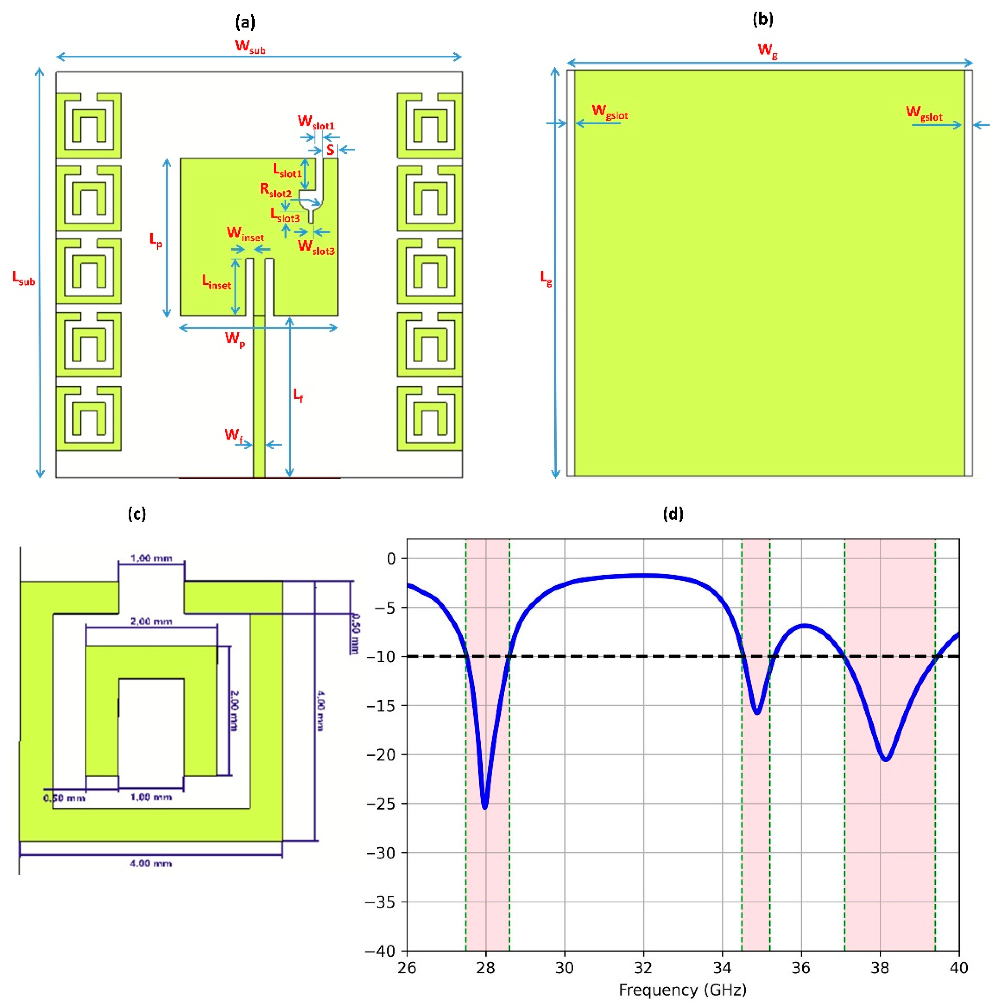
  • Compact antenna design, measuring a mere 50 × 50 × 0.787 mm3 (4.67λo × 4.67λo × 0.73λo), delivers good performance, catering to meet the needs of modern communication devices constrained by limited space.
  • Operates within the tri-band 28, 35, and 38 GHz, offering the promise of expedited and more efficient wireless communication solutions.
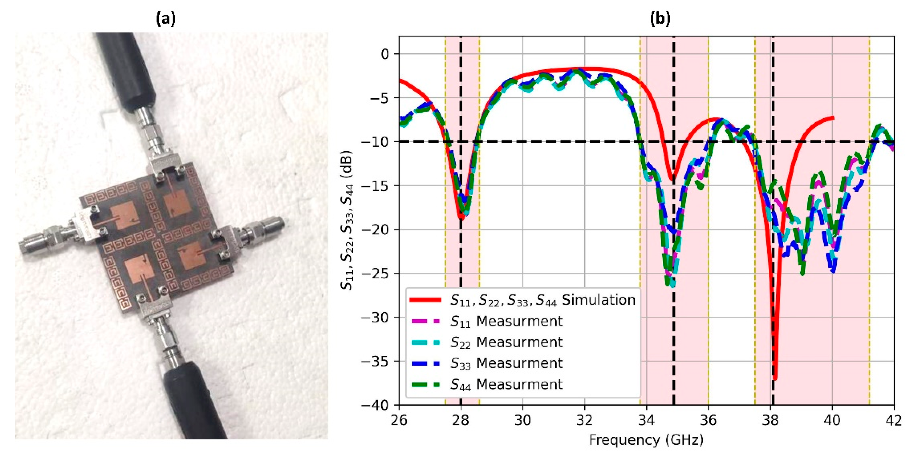
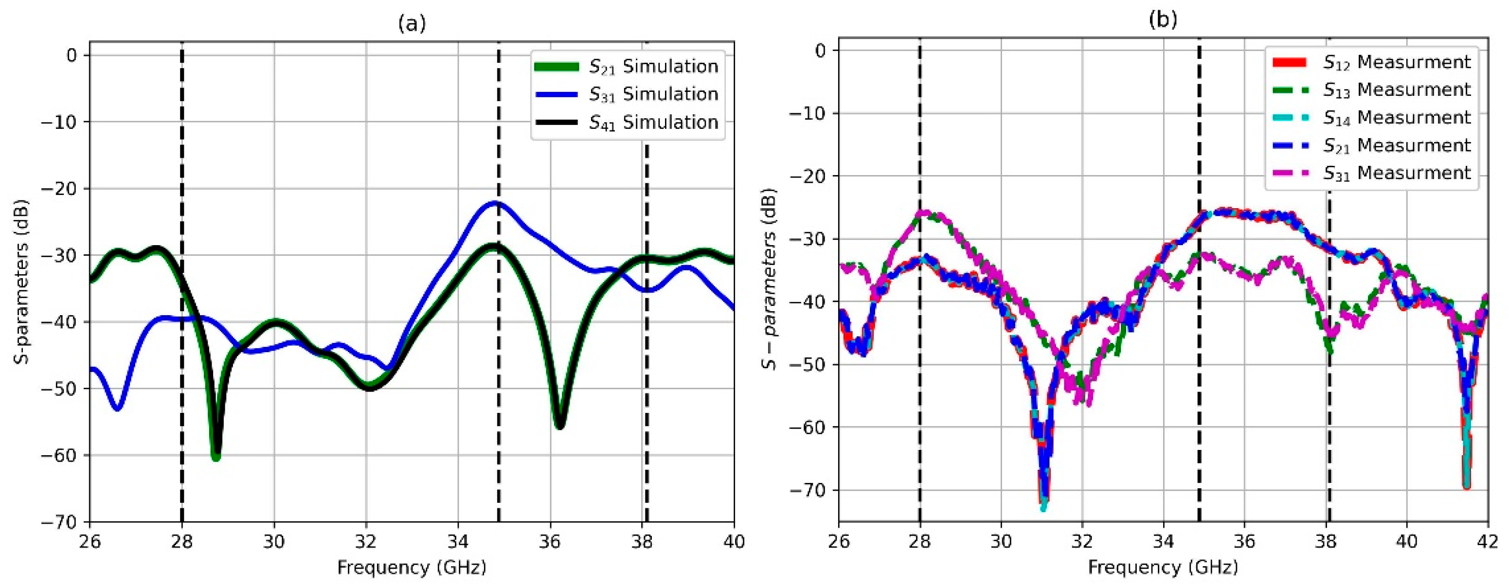
  • Features 34.5, 22, and 30 dB isolation between its ports, by which it effectively minimizes interference, ensuring the clarity and strength of the signals transmitted.
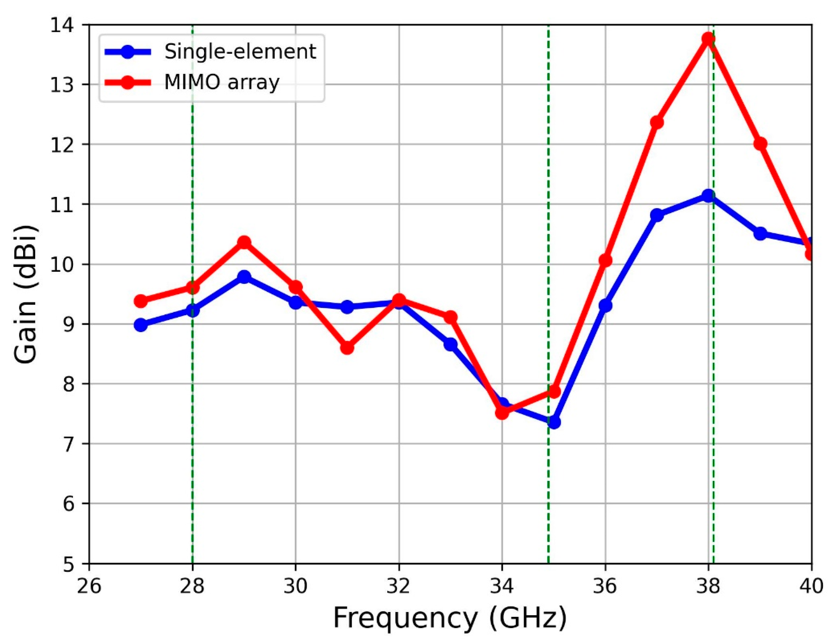
  • Achieves high gains of 9.6, 7.8, and 13.7 dBi in the tri-band, respectively, which enhances communication range and quality, facilitating improved transmission capabilities.
Experimental testing has validated the antenna’s performance, making it a reliable choice for upcoming 5G mmWave wireless applications.
The rest of this report is structured as follows: Section 2 presents the antenna design methodology, including the geometry, substrate selection, and tri-band operation for both the single-element configuration and the four-port MIMO array, along with comprehensive simulation results. Section 3 validates the design through experimental measurements, comparing prototypes’ performance with simulations. Section 4 concludes the work by summarizing its key achievements.

2. Design and Analysis

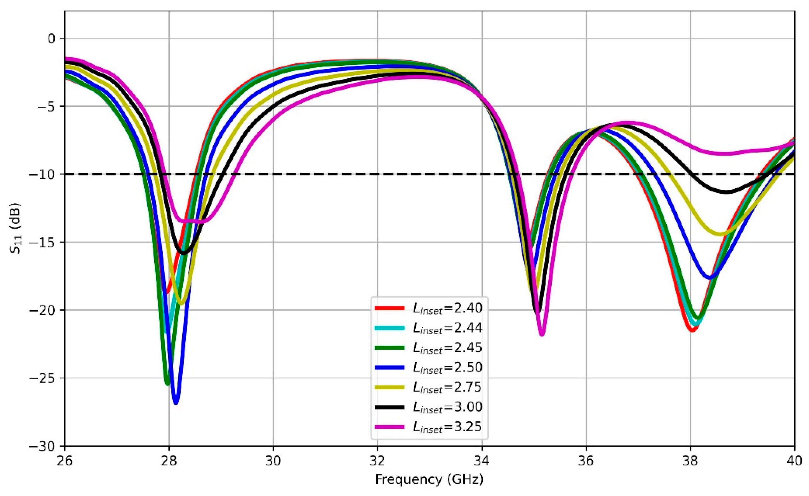
2.1. Single Antenna Element

Before investigating the proposed MIMO design, it is essential first to explore the design and operational principles of a single antenna element. The geometry of the visualized tri-band antenna is illustrated in Figure 1. This antenna, printed on a low-loss Rogers RT-5880 substrate with a height (h) of 0.787 mm and a dielectric constant (εr) of 2.2, and a 9 × 10⁻⁴ loss-tangent, encompasses a modified rectangular patch fed by a microstrip line. The antenna is a single-patch antenna with dimensions Wp × Lp, with two inset feeders with dimensions Winset × Linset to enhance the impedance matching of the antenna. The design features the rectangular slot 1 with dimensions of Wslot1 × Lslot1, established at a distance S from the right edge of the patch. This is followed by slot 2, which is a half-circle with a radius of Rslot2. Another rectangular slot is created to enhance the antenna’s bandwidth for the three bands. Feeding the slotted patch is a 50 Ω microstrip feedline with Wf and Lf dimensions. The substrate dimensions are Wsub and Lsub, and the ground plate dimensions are also Wg and Lg. Impedance matching at resonant frequencies was attained using optimization for slot dimensions and the inset feeder (Winset and Linset). Optimal performance was achieved with dimensions being 0.2 mm wide and 2.5 mm long for the inset feeder. All the design parameters are listed as shown in Table 1. The design incorporates an MTM unit cell with the dimensions shown in Figure 1c. The reflection coefficient (S11) of the antenna, shown in Figure 1d, reveals resonant frequencies at 28, 34.95, and 38.16 GHz, with reflection coefficients below −25 dB, −15.5 dB, and −20.5 dB at their corresponding frequencies of interest. The bandwidths around these resonance frequencies are 1.0 GHz, 0.83 GHz and 1.9 GHz as the bands of interest, respectively. These simulated results provide critical insights for performance analysis and optimization during the pre-fabrication phase.
After conducting a parametric sweep, it became evident that the inset length (Linset) holds paramount importance among the various dimensions listed in Table 1. Hence, altering the Linset from 2.4 to 3.5 would have a substantial impact on each band resonance frequency, as well as the reflection coefficient values and the achieved bandwidth, as demonstrated in Figure 2. The reason behind this lies in the intricate relationship between the lengths of the two insets and the input impedance of the antenna. Altering length leads to a consequential modulation of the impedance characteristics, which in turn plays a pivotal role in determining the reflection properties, resonance behavior, and bandwidth efficiency of the antenna. The best reflection characteristics of the tri-band were obtained at an Linset value of 2.5 mm.
The radiation patterns in Figure 3 characterize the single-element antenna’s performance across frequencies in both E-plane and H-plane. These patterns reveal key radiation characteristics including the gain, main lobe direction, and beamwidth:
At 28 GHz
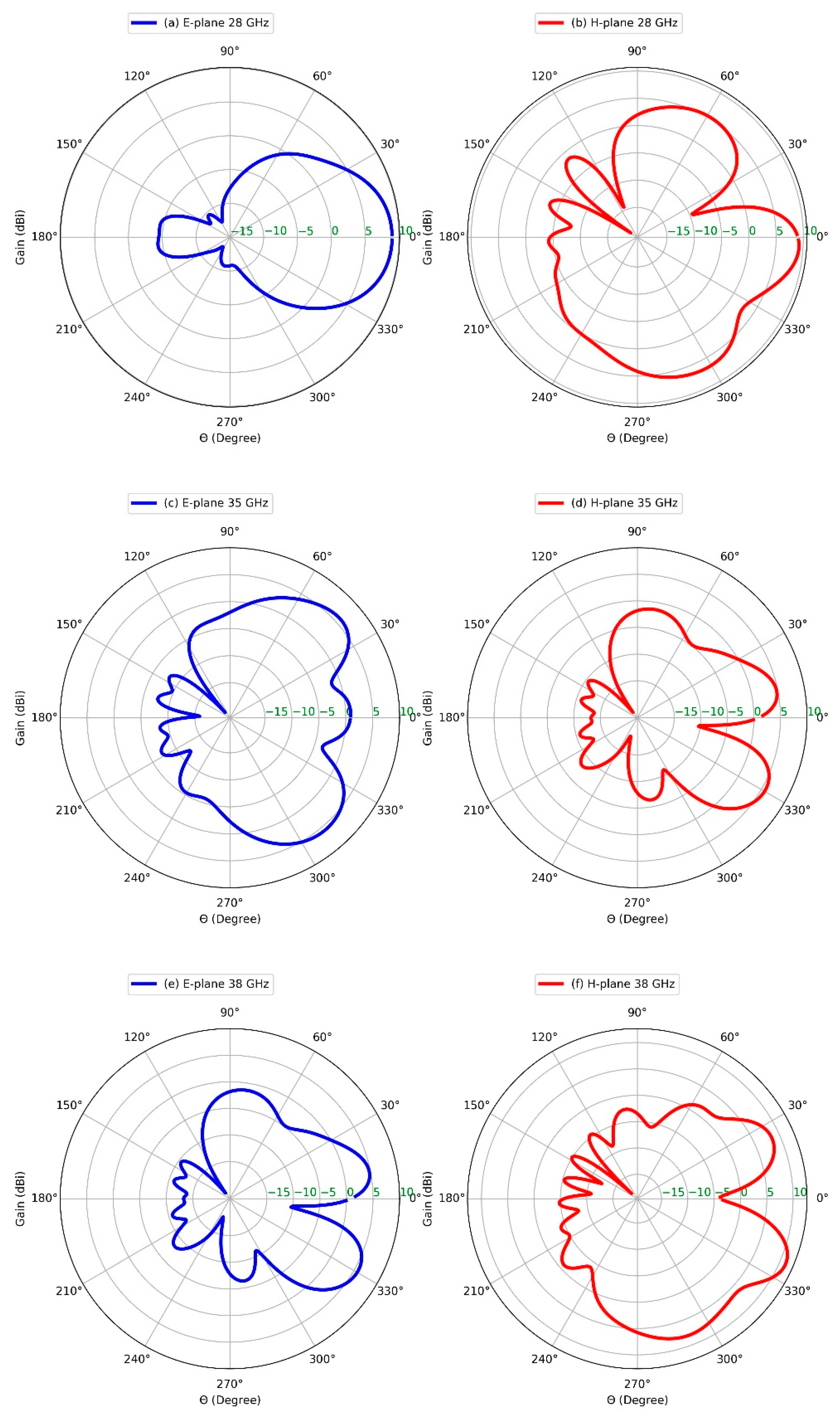
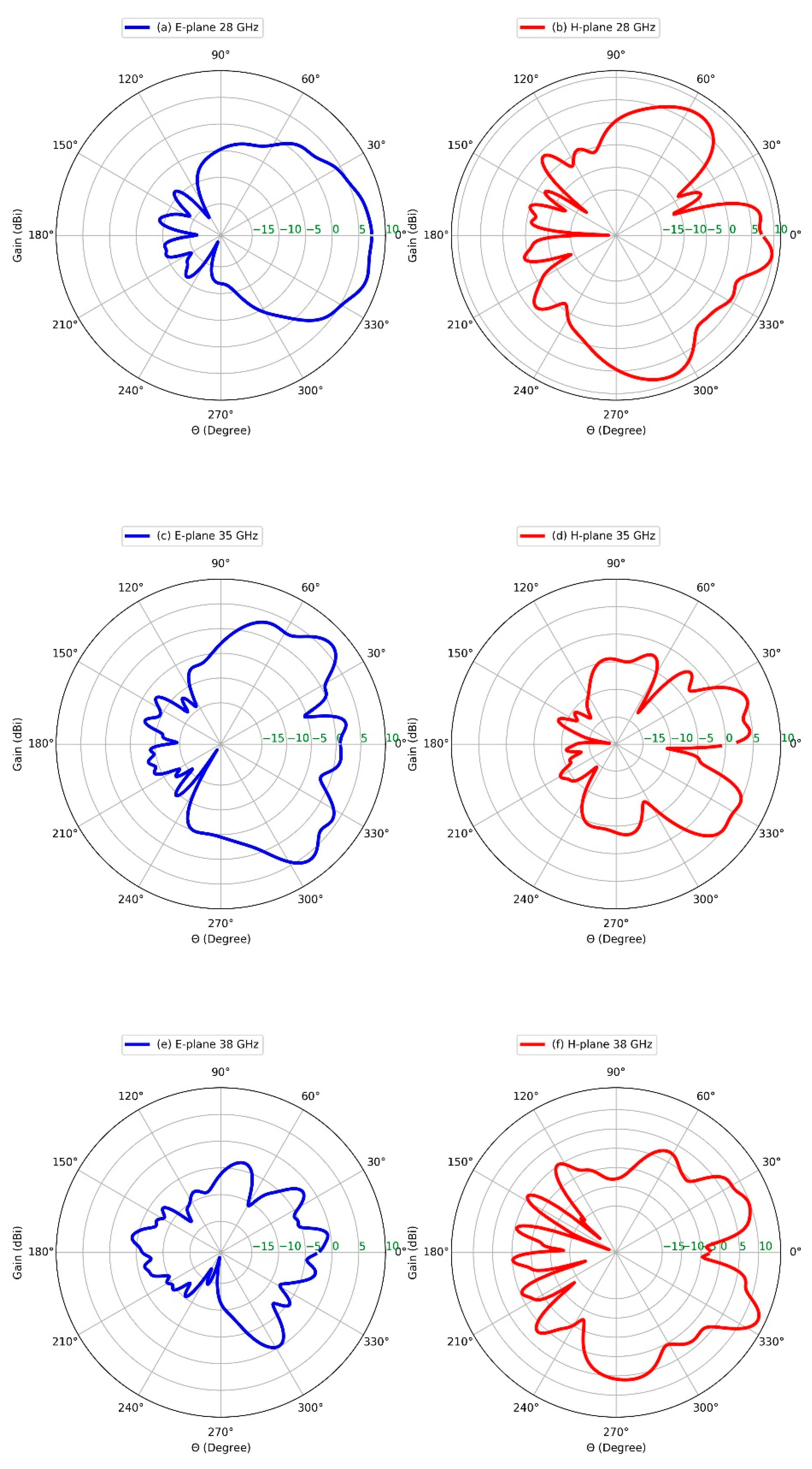
  • E-plane: 9 dBi gain, main lobe at θ = 4° (beamwidth = 50.8°).
  • H-plane: 9.3 dBi gain, main lobe at θ = 0° (beamwidth = 27.3°).
At 35 GHz
  • E-plane: 5.9 dBi gain, main lobe at θ = 42° (beamwidth = 36.9°).
  • H-plane: 5.7 dBi gain, main lobe at θ = 29° (beamwidth = 26.2°).
At 38 GHz
  • E-plane: Weaker gain pattern.
  • H-plane: 11.2 dBi gain, main lobe at θ = 24° (beamwidth = 21.4°).
This comprehensive analysis of radiation patterns across frequencies provides essential insights for antenna design optimization, ensuring efficient radiation characteristics and the desired performance across operational bands.

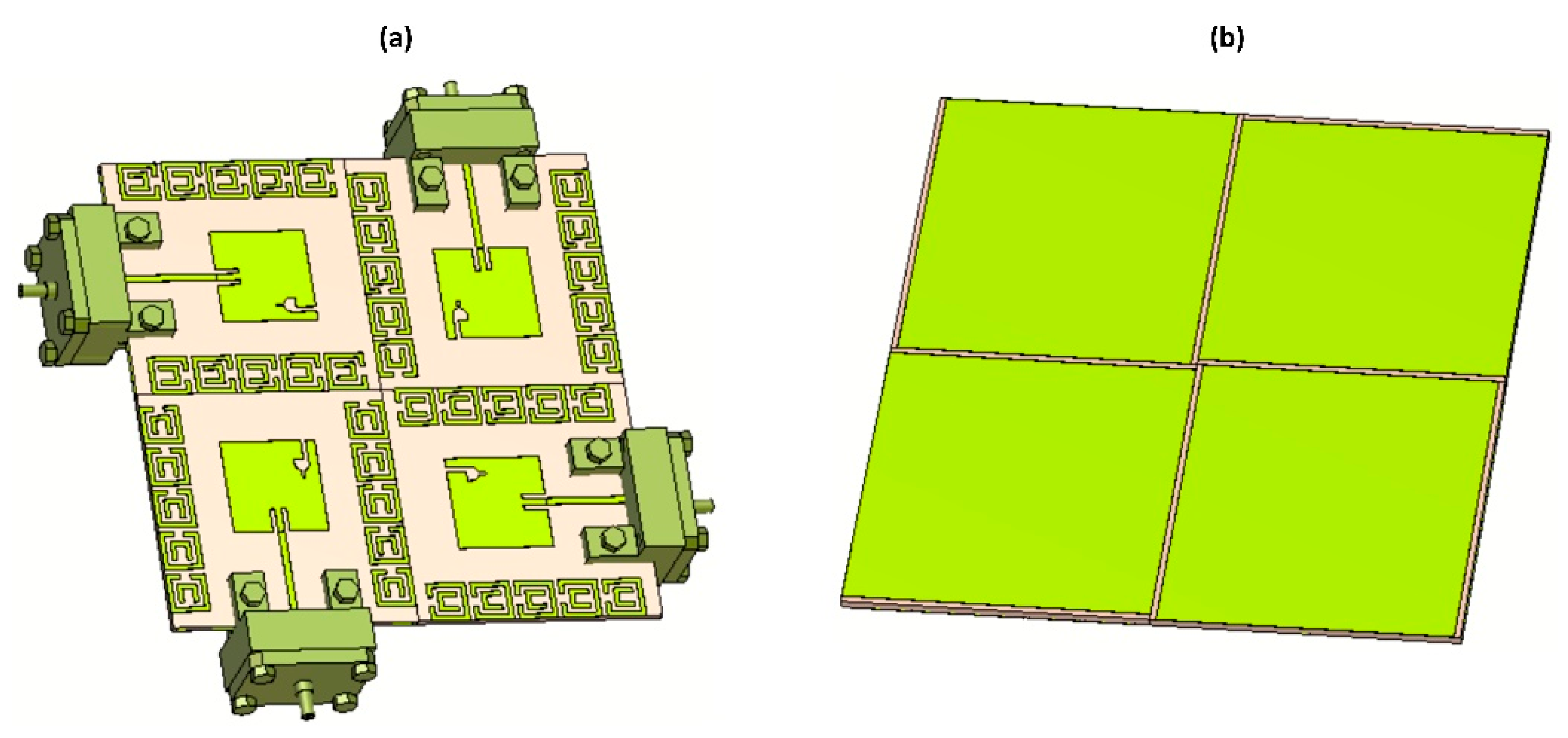
2.2. Four-Element MIMO Antenna

This design is specifically required for a four-port MIMO antenna array that operates at two frequency bands with centers around 28, 35, and 38 GHz. The spacing between antenna elements is emphasized with the aim of improving MIMO isolation. The MIMO antenna assemblage consists of 4 different elements that occupy a common area of 50 × 50 mm², alongside the substrate which is the same as for the single-element antenna. The MIMO antenna structure is displayed in Figure 4a for both top and bottom views, with each port connected to SubMiniature version A (SMA). As compared to those results obtained for a single-element antenna, the simulated reflection coefficient showed a minor degradation to −18 dB at 28 GHz and 35 GHz. However, there was a significant improvement to below −37 dB at 38 GHz. The slight deviation observed in the MIMO S-parameters, particularly S11, compared to those of a single-element antenna, can be attributed to several factors intrinsic to MIMO systems. In MIMO configurations, where multiple antennas are closely positioned, interactions such as mutual coupling between antennas can impact individual antenna performance. This coupling can alter impedance matching and radiation patterns, leading to differences in S11 parameters. Additionally, the placement of antennas in a MIMO array, the characteristics of the feed network, environmental conditions, and cross-coupling effects all contribute to the variations in S11 parameters between MIMO setups and single-element antennas. Understanding and accounting for these complexities are vital in optimizing MIMO antenna designs to achieve the desired performance levels in real-world scenarios.
In a MIMO configuration, significant coupling arising from surface wave interactions can profoundly impact the system’s performance. Hence, it is imperative to minimize such interference or crosstalk behavior to the greatest extent possible. As a consequence of these efforts, reductions in coupling of −34.5, −22, and −30 dB were achieved at 28 GHz, 35 GHz, and 38 GHz, respectively. These outcomes reveal successful mitigation of adverse coupling effects and the realization of the improved isolation and performance over the tri-band.

2.3. MIMO Assessment

There are numerous metrics for evaluating the performance of the MIMO antenna systems. The envelope correlation coefficient (ECC) can be used to judge how well the envelopes of signals received by different antennas correlate with each other. The lower the value of ECC, the better the diversity performance, as this would imply that the antennas are receiving signals that are largely uncorrelated, thus enhancing the diversity gain. ECC evaluates the correlation between received signals by antenna pairs, normalized to their total received power. This evaluation parameter can be computed using the following expression:
E C C = S i i S i j + S j i S j j 2 1 S i i 2 + S j i 2 + 1 S j j 2 + S i j 2
where S i i and S j j   represent the complex conjugate and complex values of the reflection coefficients for antennas i and j, respectively, while S i j   and S j i   denote the transmission coefficients between antennas i and j (with S j i being the complex conjugate), describing the signal coupling between these antenna pairs in the scattering matrix.
The diversity gain (DG) assigns a numerical value to measure the degree of improvement in the quality of the received signal using multiple antennas to mitigate fading effects by utilizing spatial diversity to enhance reliability. Considering the dependence of DG on ECC, it is computed using
D G = 10 1 ( E C C ) 2
The mean effective gain (MEG) provides a good picture of how an antenna pattern performs with average power gain in all directions, thereby denoting the whole efficiency of the system in its mean transmission and reception of signals. Effective diversity gain (EDG) provides a comprehensive evaluation of system diversity performance by incorporating both diversity gain and antenna correlation effects. Meanwhile, the channel capacity loss (CCL) quantifies the decrease in the maximum attainable data rate owing to channel impairments such as noise and interference, reflecting their impact on the information-theoretic capacity limits. CCL is determined by computing the logarithm of the norm of the received signal coefficients. This calculation incorporates both the correlation between antenna elements and the received power distribution. The CCL can be expressed as
  C C L = log 2 β R   where     β R = β 11 β 12 β 1 N β 21 β 22 β 2 N β N 1 β N 2 β N N where     β i i = 1 n = 1 N S i n S n i and     β i j = n = 1 N S i n S n i
βR represents a matrix of the received signal coefficients. β i i denotes coefficients of power received by antenna i after computing powers received by other antennas. β i j denotes correlation coefficients between signals received by antennas i and j, in which their values are counted from 1 up to N, where N signifies the number of antennas of the MIMO structure.
Figure 5 displays ECC and DG concerning frequency variations. Notably, the ECC values exhibited in the plot are markedly below the conventional benchmark of 0.5 across the computed spectrum. Simultaneously, the DG is observed to approach approximately 10 dB, signifying robust signal reception and mitigation of the influence of fading. Moreover, the calculated CCL reveals promising results: at 28 GHz, CCL stands at 0.039; at 35 GHz, it rises slightly to 0.203; and at 38 GHz, it falls to 0.024. These computed CCL values notably outperform the standard reference of 0.4 bit/Hz/sec, indicating a significant CCL reduction.
In Figure 6, the comparison between the gains of the MIMO antenna and the single-element antenna is illustrated across various frequencies. The results reveal a significantly higher gain for the MIMO antenna setup. Specifically, at 28 GHz, the MIMO antenna displays a gain of 9.6 dBi, slightly surpassing the gain of the single-element antenna, which is 9.2 dBi. Similarly, at 35 GHz, the MIMO antenna achieves a gain of 7.8 dBi in contrast to 7.3 dBi for the single-element antenna. Furthermore, at 38 GHz, the MIMO antenna exhibits a gain of 13.8 dBi compared to 11.1 dBi for the single-element antenna. The higher gains of the MIMO antenna over the single-element antenna come from advantages like spatial diversity, spatial multiplexing, beamforming, interference mitigation, increased channel capacity, and frequency diversity. These features collectively enhance signal quality, spectral efficiency, and interference suppression, resulting in a superior gain performance across various frequencies.
The radiation pattern analysis shown in Figure 7 depicts the MIMO antenna’s radiation characteristics across frequencies as follows:
28 GHz
  • E-plane: 7.7 dBi gain, main lobe: θ = 16°, beamwidth: 60.7°.
  • H-plane: 9.8 dBi gain, main lobe: θ = 7°, beamwidth: 25°.
35 GHz
  • E-plane: 6.7 dBi gain, main lobe: θ = 42°, beamwidth: 19.6°.
  • H-plane: 5.2 dBi gain, main lobe: θ = 19°, beamwidth: 26°.
38 GHz
  • E-plane: reduced gain performance.
  • H-plane: 13.8 dBi gain, main lobe: θ = 26°, beamwidth: 12°.
Frequency-dependent directivity variations are evident, particularly in beamwidth narrowing at higher frequencies. The H-plane maintains superior gain characteristics compared to the E-plane across all frequencies. Notable beam steering occurs with frequency changes (main lobe shifts from 7° to 26° in the H-plane). This pattern analysis enables precise antenna performance prediction, the identification of optimal operational frequencies, and the validation of design objectives for MIMO applications.

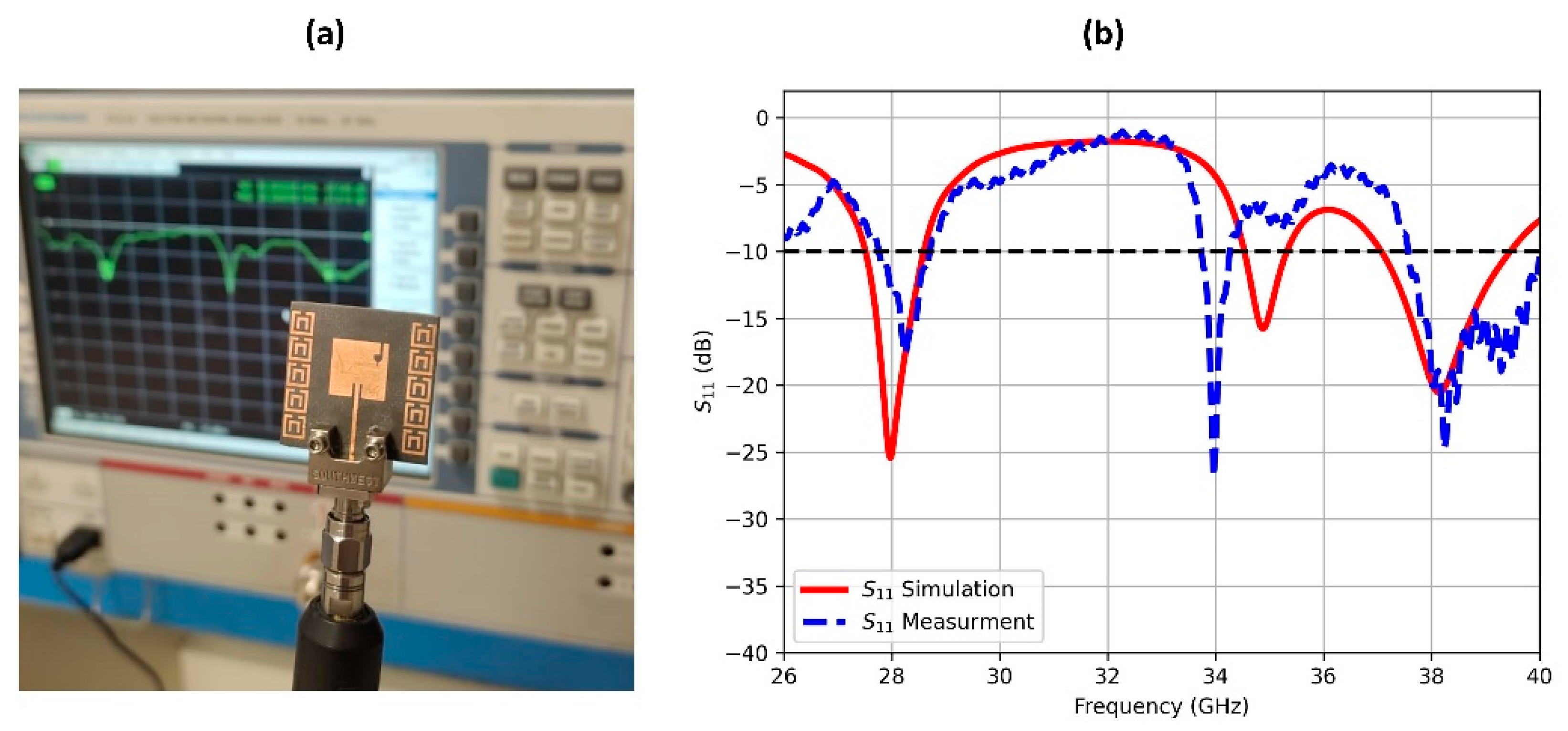
3. Measurement Results

The antenna prototypes were characterized using a 67 GHz vector network analyzer (VNA) to measure their scattering parameters. Both single-element and four-port MIMO configurations were evaluated using precision 1.85 mm end-launch connectors, as illustrated in Figure 8. Figure 8a specifically shows the measurement setup for the single-element prototype connected via an SMA connector to the VNA.
The comparison between measured and simulated reflection coefficients, presented in Figure 8b, demonstrates good agreement in both the first and third frequency bands. However, an approximately 1 GHz frequency shift was observed in the middle band. This discrepancy may be attributed to several factors including impedance mismatches, SMA connector effects, environmental influences during measurement, or inherent approximations in the simulation models. Despite this frequency shift, the measured bandwidths across all three bands remained consistent with the simulated results, representing good overall consistency between the fabricated design and its computed performance. As a rapid fix, laser trimming or post-fabrication tuning can experimentally adjust this frequency shift in the middle band without altering the 28/38 GHz bands.
The scattering parameters for the MIMO antenna were assessed using the VNA, with the unconnected ports terminated by a 50 Ω matching load, as depicted in Figure 9a. This methodology ensures accurate measurement of the inter-port coupling effects while maintaining impedance matching for the unmeasured ports, contributing to a comprehensive assessment of the antenna’s performance characteristics. Figure 9b displays the results of the measured reflection coefficients of each MIMO port (S11, S22, S33, and S44) as compared to those of the simulated results. A noteworthy consistency is observed between the simulation and experimental measurements, highlighting the reliability of the analysis. Furthermore, a notable increase is observed in the bandwidth of each one of the three frequency bands to 1.1, 2.2, and 3.7 GHz, respectively. The reflection coefficients are accompanied with a substantial reduction in loss for all of the measured antenna ports. This emphasizes the efficacy of the design enhancements in improving overall antenna performance, highlighting the importance of accurate simulations and careful experimental validation in optimizing the antenna characteristics.
Figure 10 demonstrates simulated/measured S-parameters for the MIMO configuration. The close correlation between the simulation and measurement results indicates significantly reduced mutual coupling between the antenna ports. The measured S21 isolation is slightly degraded as compared to the simulation results; this stems from unmodeled practical effects including fabrication tolerances (dielectric variation, etching precision), SMA connector parasitics and imperfect launches, and substrate/ground-coupled surface waves. At mmWave frequencies, sub-100 μm dimensional errors significantly impact coupling. Improved agreement requires EM models incorporating measured material data and connector S-parameters. Despite this, there is strong agreement between simulation and measurement that still reveals excellent isolation performance across all three operational frequency bands, validating the effectiveness of the incorporated MTM design in refining MIMO isolation. The improved isolation directly contributes to reduced inter-port interference, ultimately improving the overall antenna system performance. These results confirm the successful implementation of the metamaterial approach in achieving superior isolation characteristics for multi-port MIMO antenna systems.
Table 2 presents a comparative analysis between the proposed antenna design and the state-of-the-art implementations reported in the recent literature. The benchmarking results demonstrate that our design achieves a competitive performance across key metrics including operational bandwidth, radiation gain, and port-to-port isolation. This evaluation reveals several notable advantages of the proposed configuration: (1) improved bandwidth characteristics across operational frequencies, (2) consistent gain performance, (3) enhanced isolation compared to conventional designs. These results position the proposed design as a viable solution for next-generation wireless systems requiring high-performance antenna arrays.

4. Conclusions

This work presents a new high-performance MIMO antenna with millimeter-wave (mmWave) 5G wireless communication allocations. The tri-band working frequencies are 28, 35, and 38 GHz. A compact four-port MIMO antenna, measuring 50 × 50 mm2 exhibits good performance, with recorded peak gains of 9.6, 7.8, and 13.7 dBi at 28, 35, and 38 GHz. The bandwidths acquired are 1.1, 2.2, and 3.7 GHz for the tri-band. The performance of the antenna was significantly improved through careful spacing of the elements and a decoupling method using metamaterial cells. This brought about the minimization of coupling between antenna elements, leading to an efficient MIMO performance with a very low envelope correlation coefficient of 0.00015, a further high diversity gain nearing 10 dB, and high isolation of 34.5, 22, and 30 dB, in the tri-band. Experimental verification has proven the design’s effectiveness for broadband mmWave system implementation. Additional experimental characterization—including gain–frequency response and radiation pattern measurements—remains to be conducted for a comprehensive performance validation.

Author Contributions

Conceptualization, N.A. and M.S.; methodology, M.S.; software, N.A.; validation, M.S. and N.A.; formal analysis, M.S.; investigation, N.A.; resources, N.A.; data curation, M.S.; writing—original draft preparation, N.A. and M.S.; writing—review and editing, N.A. and M.S. All authors have read and agreed to the published version of the manuscript.

Funding

This research received no external funding.

Institutional Review Board Statement

Not applicable.

Informed Consent Statement

Not applicable.

Data Availability Statement

The original contributions presented in this study are included in the article. Further inquiries can be directed to the corresponding authors.

Acknowledgments

The researchers would like to thank the Deanship of Graduate Studies and Scientific Research at Qassim University for financial support (QU-APC-2025).

Conflicts of Interest

The authors declare no conflicts of interest.

References

  1. Federal Communications Commission. Report, order, and further notice of proposed rulemaking. Matter Revis. Comm. Rules Ensure Compat. Enhanc. 2016, 911, 94–102. [Google Scholar]
  2. Attiah, M.L.; Isa, A.A.; Zakaria, Z.; Abdulhameed, M.K.; Mohsen, M.K.; Ali, I. A survey of mmWave user association mechanisms and spectrum sharing approaches: An overview, open issues and challenges, future research trends. Wirel. Netw. 2020, 26, 2487–2514. [Google Scholar] [CrossRef]
  3. Mandloi, M.; Gurjar, D.; Pattanayak, P.; Nguyen, H. 5G and Beyond Wireless Systems; Springer: Berlin, Germany, 2021. [Google Scholar]
  4. Aboagye, S.; Saeidi, M.A.; Tabassum, H.; Tayyar, Y.; Hossain, E.; Yang, H.C.; Alouini, M.S. Multi-band wireless communication networks: Fundamentals, challenges, and resource allocation. IEEE Trans. Commun. 2024, 72, 4333–4383. [Google Scholar] [CrossRef]
  5. JY The role of millimeter-wave technologies in 5G/6G wireless communications. IEEE J. Microw. 2021, 1, 101–122. [CrossRef]
  6. Daraseliya, A.; Korshykov, M.; Sopin, E.; Moltchanov, D.; Andreev, S.; Samouylov, K. Coexistence analysis of 5G NR unlicensed and WiGig in millimeter-wave spectrum. IEEE Trans. Veh. Technol. 2021, 20, 11721–11735. [Google Scholar] [CrossRef]
  7. Xu, X.; Chen, Q.; Jiang, H.; Huang, J. Millimeter-wave NR-U and WiGig coexistence: Joint user grouping, beam coordination, and power control. IEEE Trans. Wirel. Commun. 2021, 21, 2352–2367. [Google Scholar] [CrossRef]
  8. Alnemr, F.; Ahmed, M.F.; Shaalan, A.A. A compact 28/38 GHz MIMO circularly polarized antenna for 5 G applications. J. Infrared Millim. Terahertz Waves 2021, 42, 338–355. [Google Scholar] [CrossRef]
  9. Sabek, A.R.; Ali, W.A.; Ibrahim, A.A. Minimally coupled two-element MIMO antenna with dual band (28/38 GHz) for 5G wireless communications. J. Infrared Millim. Terahertz Waves 2022, 43, 335–348. [Google Scholar] [CrossRef]
  10. Cuneray, K.; Akcam, N.; Okan, T.; Arican, G.O. 28/38 GHz dual-band MIMO antenna with wideband and high gain properties for 5G applications. AEU-Int. J. Electron. Commun. 2023, 1, 154553. [Google Scholar] [CrossRef]
  11. Ali, S.A.; Wajid, M.; Kumar, A.; Alam, M.S. Design challenges and possible solutions for 5G SIW MIMO and phased array antennas: A review. IEEE Access 2022, 10, 88567–88594. [Google Scholar] [CrossRef]
  12. Tiwari, P.; Gahlaut, V.; Kaushik, M.; Rani, P.; Shastri, A.; Singh, B. Advancing 5G connectivity: A comprehensive review of MIMO antennas for 5G applications. Int. J. Antennas Propag. 2023, 2023, 5906721. [Google Scholar] [CrossRef]
  13. Wang, Z.; Zhang, J.; Du, H.; Wei, E.I.; Ai, B.; Niyato, D.; Debbah, M. Extremely large-scale MIMO: Fundamentals, challenges, solutions, and future directions. IEEE Wirel. Commun. 2023, 31, 117–124. [Google Scholar] [CrossRef]
  14. Raj, T.; Mishra, R.; Kumar, P.; Kapoor, A. Advances in MIMO antenna design for 5G: A comprehensive review. Sensors 2023, 12, 6329. [Google Scholar] [CrossRef]
  15. Jemaludin, N.H.; Al-Gburi, A.J.; Elabd, R.H.; Saeidi, T.; Akbar, M.F.; Ibrahim, I.M.; Zakaria, Z. A comprehensive review on MIMO antennas for 5G smartphones: Mutual coupling techniques, comparative studies, SAR analysis, and future directions. Results Eng. 2024, 10, 102712. [Google Scholar] [CrossRef]
  16. Kamal, M.M.; Yang, S.; Ren, X.; Altaf, A.; Kiani, S.H.; Anjum, M.R.; Iqbal, A.; Asif, M.; Saeed, S.I. Infinity Shell Shaped MIMO Antenna Array for mm-Wave 5G Applications. Electronics 2021, 10, 165. [Google Scholar] [CrossRef]
  17. Sehrai, D.A.; Abdullah, M.; Altaf, A.; Kiani, S.H.; Muhammad, F.; Tufail, M.; Irfan, M.; Glowacz, A.; Rahman, S. A Novel High Gain Wideband MIMO Antenna for 5G Millimeter Wave Applications. Electronics 2020, 9, 1031. [Google Scholar] [CrossRef]
  18. Tiwari, R.N.; Sharma, D.; Singh, P.; Kumar, P. A flexible dual-band 4 × 4 MIMO antenna for 5G mm-wave 28/38 GHz wearable applications. Sci. Rep. 2024, 14, 14324. [Google Scholar] [CrossRef] [PubMed]
  19. Wang, L.; Li, H.; Shi, Y.; Chen, M.; Li, C.; Wang, H.; Zheng, L. An elliptical dual-band antenna with crescent slot for 5G mm Wave applications. J. Phys. Conf. Ser. 2024, 2807, 012033. [Google Scholar] [CrossRef]
  20. Sghaier, N.; Belkadi, A.; Hassine, I.B.; Latrach, L.; Gharsallah, A. Millimeter-wave dual-band MIMO antennas for 5G wireless applications. J. Infrared Millim. Terahertz Waves 2023, 44, 297–312. [Google Scholar] [CrossRef]
  21. Sharma, P.; Tiwari, R.N.; Singh, P.; Kumar, P.; Kanaujia, B.K. MIMO antennas: Design approaches, techniques and applications. Sensors 2022, 22, 7813. [Google Scholar] [CrossRef]
  22. Kumar, P.; Ali, T.; Pai, M.M. Electromagnetic metamaterials: A new paradigm of antenna design. IEEE Access 2021, 22, 18722–18751. [Google Scholar] [CrossRef]
  23. Ketzaki, D.A.; Yioultsis, T.V. Metamaterial-based design of planar compact MIMO monopoles. IEEE Trans. Antennas Propag. 2013, 30, 2758–2766. [Google Scholar] [CrossRef]
  24. Alsaab, N.; Alhassoon, K.; Alsaleem, F.; Alsunaydih, F.N.; Madbouly, S.O.; Khaleel, S.A.; Ameen, A.M.; Shaban, M. High-Performance Series-Fed Array Multiple-Input Multiple-Output Antenna for Millimeter-Wave 5G Networks. Sensors 2025, 25, 1036. [Google Scholar] [CrossRef]
  25. Shaban, M. Development and Implementation of High-Gain, and High-Isolation Multi-Input Multi-Output Antenna for 5G mmWave Communications. Telecom 2025, 6, 14. [Google Scholar] [CrossRef]
  26. Alsalman, A.; Alhumaid, A.; Alnogithan, A.; Hamad, E.K.; Shaban, M. Reconfigurable 28/38 GHz wideband and high isolation MIMO antenna for advanced mmWave applications. J. Electr. Eng. 2024, 75, 467–483. [Google Scholar] [CrossRef]
  27. Shaban, M. Design and Modeling of a Reconfigurable Multiple Input, Multiple Output Antenna for 24 GHz Radar Sensors. Modelling 2025, 6, 2. [Google Scholar] [CrossRef]
  28. Alibakhshikenari, M.; Virdee, B.S.; Shukla, P.; See, C.H.; Abd-Alhameed, R.A.; Falcone, F.; Quazzane, K.; Limiti, E. Isolation enhancement of densely packed array antennas with periodic MTM-photonic bandgap for SAR and MIMO systems. IET Microw. Antennas Propag. 2020, 14, 183–188. [Google Scholar] [CrossRef]
  29. Alibakhshikenari, M.; Virdee, B.S.; See, C.H.; Abd-Alhameed, R.A.; Falcone, F.; Limiti, E. Surface wave reduction in antenna arrays using metasurface inclusion for MIMO and SAR systems. Radio Sci. 2019, 54, 1067–1075. [Google Scholar] [CrossRef]
  30. Alibakhshikenari, M.; Khalily, M.; Virdee, B.S.; See, C.H.; Abd-Alhameed, R.A.; Limiti, E. Mutual-coupling isolation using embedded metamaterial EM bandgap decoupling slab for densely packed array antennas. IEEE Access 2019, 9, 51827–51840. [Google Scholar] [CrossRef]
  31. Wang, H.; Xiao, P.; Li, X. Channel parameter estimation of mmWave MIMO system in urban traffic scene: A training channel-based method. IEEE Trans. Intell. Transp. Syst. 2022, 25, 754–762. [Google Scholar] [CrossRef]
  32. Wang, H.; Xu, L.; Yan, Z.; Gulliver, T.A. Low-complexity MIMO-FBMC sparse channel parameter estimation for industrial big data communications. IEEE Trans. Ind. Inform. 2020, 17, 3422–3430. [Google Scholar] [CrossRef]
  33. Khalid, M.; Iffat Naqvi, S.; Hussain, N.; Rahman, M.; Fawad Mirjavadi, S.S.; Khan, M.J.; Amin, Y. 4-Port MIMO antenna with defected ground structure for 5G millimeter wave applications. Electronics 2020, 9, 71. [Google Scholar] [CrossRef]
  34. Ramanathan, S.; Maria, A.B. A Compact Four-Element MIMO Antenna for 5 G Millimeter-Wave (37–39 GHz) Applications. J. Infrared Millim. Terahertz Waves 2024, 23, 604–620. [Google Scholar] [CrossRef]
  35. Abbasi, N.A.; Virdee, B.; Din, I.U.; Ullah, S.; Althuwayb, A.A.; Rashid, N.; Soruri, M.; See, C.H. High-Isolation Array Antenna Design for 5G mm-Wave MIMO Applications. J. Infrared Millim. Terahertz Waves 2025, 46, 12. [Google Scholar] [CrossRef]
  36. Farahat, A.E.; Hussein, K.F. Dual-band (28/38 GHz) wideband MIMO antenna for 5G mobile applications. IEEE Access 2022, 10, 32213–32223. [Google Scholar] [CrossRef]
  37. Marzouk, H.M.; Ahmed, M.I.; Shaalan, A.A. Novel dual-band 28/38 GHz MIMO antennas for 5G mobile applications. Prog. Electromagn. Res. C 2019, 93, 103–117. [Google Scholar] [CrossRef]
  38. Sghaier, N.; Belkadi, A.; Malleh, M.A.; Latrach, L.; Hassine, I.B. Design and Analysis of a Compact MIMO Antenna for 5G mmWave N257, N260, and N262 Band Applications. J. Infrared Millim. Terahertz Waves 2024, 45, 247–264. [Google Scholar] [CrossRef]
Figure 1. (a) Front, (b) back view of single element antenna, (c) MTM unit cell dimensions, and (d) reflection coefficient parameter, S11, versus frequency.
Applsci 15 06857 g001
Figure 2. Parametric sweep of the antenna design illustrating the impact of Linset on reflection coefficient versus frequency.
Applsci 15 06857 g002
Figure 3. Radiation patterns of single-element antenna: (a) E-plane, (b) H-plane at 28 GHz, (c) E-plane, (d) H-plane at 35 GHz, (e) E-plane, and (f) H-plane at 38 GHz.
Applsci 15 06857 g003
Figure 4. Four-port MIMO antenna; (a) front, (b) back view with SMA connectors, and (c) simulated S-parameters versus frequency.
Applsci 15 06857 g004aApplsci 15 06857 g004b
Figure 5. (a) ECC and (b) DG versus frequency of 4-port MIMO antennas.
Applsci 15 06857 g005
Figure 6. Peak gain versus frequency of single-element and MIMO array antennas.
Applsci 15 06857 g006
Figure 7. Radiation patterns of 4-port MIMO antenna; (a) E-plane, (b) H-plane at 28 GHz, (c) E-plane, (d) H-plane at 35 GHz, (e) E-plane, and (f) H-plane at 38 GHz.
Applsci 15 06857 g007
Figure 8. (a) Measurement setup of single-element antenna and (b) measured reflection coefficient as compared to the simulated one.
Applsci 15 06857 g008
Figure 9. (a) 4-port MIMO prototype, and (b) Measured and simulated reflection coefficients for each MIMO port, S11, S22, S33, and S44.
Applsci 15 06857 g009
Figure 10. (a) Simulated and (b) measured S-parameters of 4-port MIMO antenna.
Applsci 15 06857 g010
Table 1. Single-element antenna parameters.
ParameterValue (mm)ParameterValue (mm)
Wp9.70Wf0.70
Lp9.70Lf10.0
Wslot10.50Winset0.50
Lslot12.00Linset2.50
Rslot20.60Wsub,Lsub25.0
Wslot30.25h0.787
Lslot30.76Wg,Lg25.0
S0.93Wgslot0.50
Table 2. Quantitative comparison between the proposed antenna and contemporary designs across multiple performance metrics.
Reference No.Frequency (GHz)PortsDimensions (λo and mm2)Bandwidth (GHz)Gain
(dBi)
Isolation
(dB)
[33]2842.8λo × 3.3λo (30 × 35)4.18.322
[34]3842.3λo × 2.3λo (25 × 25)2.05.025
[35]3881.5λo × 6.5λo (16 × 70)2.67.525
[36]28/3820.7λo × 0.8λo (7.5 × 8.8)1.23/1.066.6/5.8620
[37]28/3825.1λo × 10.2λo (55 × 110)1.07/1.437/827
[38]28/39/48.720.9λo × 1.5λo (10 × 16)1.8/6.2/3.89.5/11.517
This work28/35/3844.7λo × 4.7λo (50 × 50)1.1/2.2/3.79.6/7.8/13.734.5/22/30
Disclaimer/Publisher’s Note: The statements, opinions and data contained in all publications are solely those of the individual author(s) and contributor(s) and not of MDPI and/or the editor(s). MDPI and/or the editor(s) disclaim responsibility for any injury to people or property resulting from any ideas, methods, instructions or products referred to in the content.

