Abstract
Multi-thrust solid rocket motors are extensively used in tactical missiles. To effectively achieve the desired multi-thrust performance curve, firstly, the concept of modular grain is introduced. Star grain, slot grain, and end-burning grain are chosen as the fundamental templates, which can be flexibly combined to form an arbitrary multi-thrust performance curve. Secondly, a quadric approximation of the burning perimeter is derived, leading to the establishment of a governing equation for modular grain design. This equation ensures a close match between the resulting performance curve and the target one. Thirdly, the Nelder–Mead optimization algorithm is employed to maximize the propellant loading fraction and reduce the combustion chamber size. Finally, the method successfully produces single-thrust, dual-thrust, and triple-thrust grains. The results show that the relative maximum deviation between the designed and target pressure curves is less than 6.1%. Additionally, the best grain configuration is identified, which maximizes the propellant loading fraction while adhering to the throat-to-port ratio constraints. Consequently, the concept of modular grain offers a valuable approach for creating complex internal ballistic characteristics by combining simpler grain templates. This approach allows for fast, responsive motor conceptual design, prototyping, testing, and even production, thereby advancing the development of solid rocket motors in a more efficient and effective manner.
1. Introduction
The solid rocket grain, a component of the solid rocket motor, plays a crucial role in determining the rocket’s internal ballistic performance (thrust-time curve or pressure-time curve). In order to meet the requirements of some flight missions, designers need to develop solid rocket grains that exhibit a multi-thrust performance curve. Consequently, one of the key responsibilities of designers is to design a grain shape or configuration that aligns with the desired multi-thrust profiles.
Researchers and engineers have embraced the concept of combined grain to achieve complex performance curves [,,,], such as the utilization of star grain and tube grain to generate a dual-thrust performance curve [,]. Moreover, the combination of star grain and slot grain are found in the boost stage of a multi-thrust motor []. Designing combined grain configurations necessitates a substantial amount of practical knowledge, and most of the combination patterns may not produce ideal and steady thrust platforms. During every stage, large pressure fluctuations may occur. To address this issue, one may use several segments of end-burning grain with varying burning rates to make the thrust platform as steady as possible. However, the burning surface area is constrained by the end-burning grain radius. To achieve larger thrust, a larger grain radius would be required, which may not be feasible in practical applications [].
To find the most promising grain shape (or grain configuration) matching a given multi-thrust performance curve, an optimization method should be introduced. Two main optimization methods are commonly used: size optimization and shape optimization.
Size optimization involves the selection of a grain type, such as star grain or finocyl grain, by designers. The detailed parameters of the grain are then optimized using global optimization algorithms like genetic algorithms. This method is straightforward and has been extensively studied over the years [,,]. While it can achieve a performance curve that matches the given requirements, there is no mathematical guarantee of finding the best performance-matching grain. Additionally, since the grain shape is pre-selected, the results may be influenced by the designers’ experience.
On the other hand, the grain reverse design, realized by the shape optimization, does not require the pre-selection of a grain shape. Instead, the grain shape is represented using techniques like splines [] or neural networks [,,], and it gradually evolves during the iteration process. This approach allows for the exploration of complex and irregular grain shapes, resulting in excellent matches to the desired performance curve. Moreover, it may even lead to the discovery of novel grain shapes during the optimization process. However, shape optimization is computationally intensive, with 3D grain shape optimizations taking days and 2D grain shape optimizations taking hours []. Furthermore, it may present new challenges in manufacturing irregular grain shapes.
Both size optimization and shape optimization have their respective limitations and shortcomings. Therefore, it is necessary to introduce the concept of modular grain. Modular grain represents a unique category within the realm of combined grain, wherein two or three distinct grain shapes are employed as fundamental templates. These templates can be flexibly combined to achieve a wide range of performance curves, encompassing single-thrust, dual-thrust, and triple-thrust configurations. Yang [] discusses the modulization of solid rocket motor grains and suggests it might reduce the cost and cycles during the development. X-Bow Systems, the pioneer in modular solid motors, has designed and built a suite of modular solid rocket motors and small launch vehicles for both orbital and suborbital launch services []. The concept of modular grain may enable rapid and responsive motor design, prototyping, testing, and production, making the product more competitive in the market [].
In this work, we extend the concept of modular grain in four novel ways:
- (1)
- Simplicity of Basic Grain Shape Template: The geometry of the grain template should be kept as simple as possible. By minimizing complexity, the design and manufacturing process becomes more manageable and efficient.
- (2)
- Mathematical Assurance of Steadiness: The proper combination of the grain template ensures that each thrust platform remains steady. This guarantee should be achieved through rigorous mathematical calculations and governing equations.
- (3)
- Maximization of Propellant Loading Fraction: The optimization algorithm employed in modular grain design aims to maximize the propellant loading fraction. By maximizing the propellant loading fraction, the size of the propulsion system can be reduced.
- (4)
- Time Efficiency: The design and optimization process for modular grain should be completed within strict computational time constraints. The design phase should be accomplished within one second, while the optimization phase should be limited to a few minutes.
The concept of modular grain shall change the conventional grain design method from an optimization-based approach (size or shape optimization) to an equation-solving approach. The given performance curve is not approached by numerous optimization iterations but by solving governing equations. This enables us to mathematically guarantee the steadiness during each thrust platform. By leveraging the concept of modular grain, complex internal ballistic characteristics can be created by combining several simpler grain templates. With appropriate manufacturing and assembly techniques, the development cycle for new motors can be significantly reduced []. It is also important to note that our method is not intended to replace traditional engineering practices but rather to provide theoretical support and a universal framework for simplifying the design of combined rocket grains, particularly for multi-thrust scenarios.
The structure of this work is as follows:
The second section provides an introduction to the selected grain templates, the governing equations, and the optimization method. In the third section, various results and discussions are presented, encompassing the analysis of single-thrust, dual-thrust, and triple-thrust grain configurations. Finally, the fourth section presents concluding remarks based on the findings and implications of this study.
2. Design Methods
2.1. Grain Template
Figure 1 shows a typical triple-modular grain, illustrating the concept of multi-modular grain. This triple-modular grain consisting of three individual segments, wherein each segment consists of a star grain and a slot grain. After ignition, all segments start to burn simultaneously. As the first segment burns out, the thrust or chamber pressure diminishes, transitioning to the second phase. Ultimately, the second segment burns out, resulting in a further reduction in thrust or chamber pressure, marking the transition to the third phase. In our design, all propellant segments form a single grain, which is housed within a single motor case and ignited simultaneously by a single igniter. Once ignition occurs, the entire burning surface is activated, and there is no need for any isolation mechanisms.
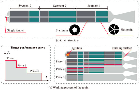
Figure 1.
Illustration of modular grain.
The reason why we chose star grain and slot grain as the fundamental templates of the modular grain lies in their burning surface behavior. As shown in Figure 2, star grain exhibits a progressive burn behavior in most cases, whereas slot grain demonstrates a regressive burn behavior. By combining these two types of grain, a neutral burning behavior may be achieved. Notably, the burning surface of star grain exhibits convex functions over time, while slot grain exhibits concave functions. This implies that their combination has the potential to ensure a very consistent and smooth thrust or chamber pressure throughout each phase. For some circumstances, end-burning grain is also used to produce the long duration thrust phase.

Figure 2.
Principle of modular grain.
The recent progress in grain reverse design also reveals the advantages of star-slot combination []. This combination is also found in the boost stage of a multi-thrust motor []. Therefore, the geometry of this combination is very simple, making it a competitive candidate as the template of modular grains.
It is also important to know that in the context of tactical missile, a multi-segmented grain sharing a single chamber is highly advantageous because it enables a more compact motor design, eliminates complex separation mechanisms, and avoids the need for multiple nozzles [].
2.2. Burning Perimeter Approximation
Figure 3 is the geometry of the star grain, where only half of the star angle is present.
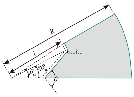
Figure 3.
Geometry of the star grain (half star angle only).
The relation between the burning perimeter (or burning surface area in 3D) of the star grain and the burned web thickness has the following analytical formula []:
where is web thickness defined by
The maximum web thickness is
The formula is too complex to make further analysis. To simplify it, a quadric approximation is proposed in this work. During the burning, the star grain will always turn into a tube grain, so the asymptotic line (or linear approximation) of Equation (1) can be written as follows:
We assume the quadric approximation has the following form:
This quadric curve must cross the point . Therefore, the coefficient to be determined (A) can be solved as follows:
In the end, the quadric approximation of star grain is written as
Figure 4 is the geometry of the slot grain, where only half of the slot is present.
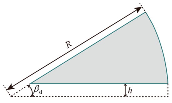
Figure 4.
Geometry of the slot grain (half star angle only).
Similarly, the burning perimeter of the slot grain has the analytical formula
The maximum web thickness is
After performing a first-order Taylor expansion at w = 0, the linear approximation of Equation (8) can be derived as follows:
We assume the quadric approximation has the following form:
This curve must go across the point , and one can solve the coefficient to be determined () as
In the end, the quadric approximation of slot grain is written as
The verification of approximation (7) and (13) is presented in Figure 5. The test results show that our quadric approximation can match the exact result very well, with a maximum deviation of less than 5%. In the subsequent section, a comprehensive derivation of the chamber pressure for a solid rocket motor will be presented.
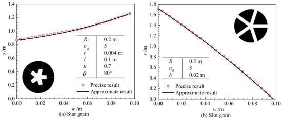
Figure 5.
The approximation of burning perimeter.
2.3. Chamber Pressure Calculation
Considering ith grain segment (star + slot), the mass flow rate (kg/s) is as follows:
where the first term is the contribution from the star grain and the second term is the contribution from the slot grain. The value t is time starting from the burning of the jth segment to present. The value means the line burning rate (m/s) of star grain at the jth segment during ith thrust phase. The value represents the line burning rate of slot grain at the jth segment during the ith thrust phase. The values and are the initial burned web thickness of star grain and slot grain at t = 0, respectively. The value and are the length of the star grain and slot grain, respectively.
In this work, erosive burning is not considered, so the line burning rate can be calculated by the empirical APN formula
where is the chamber pressure during the ith phase; is the reference burning rate of the star grain at the jth segment under reference pressure , which means different segments may have different reference burning rates; is the pressure index of the star grain at the jth segment.
Similarly, for the slot grain at the jth segment, there is
where is the reference burning rate of the slot grain at the jth segment under reference pressure ; is the pressure index of the slot grain at the jth segment.
Initial burned web thickness can be calculated as follows:
Then, substitute Equations (7) and (13) into Equation (14). After simplification, this can be organized into a quadratic function about time, as follows:
where
It is worth noting that at any moment during the ith thrust phase, the grain segments having indices smaller than i have burned out. These segments have no contribution to the total mass flow rate. Therefore, the total mass flow rate during the ith thrust stage can be calculated as follows:
The total mass flow rate can also be organized into a quadratic function
Now, according to (21), one can calculate the total mass flow rate during the ith thrust phase.
2.4. Governing Equation
Based on the aforementioned discussion, this section will provide nonlinear algebra equations for the design of modular grains. During any thrust phase, the total mass flow rate should be a constant value provided by design target, so there is
According to the pressure–flow rate relationship in a Laval nozzle, there is
where is the nozzle throat area (m2) and is the characteristic velocity of the propellant (m/s). It means that the flow rate is directly determined by the combustion chamber pressure given by the design target.
Now, there are 3N equations. To make sure the ith segment burns out simultaneously at the end of the ith thrust phase, there are the following additional equations:
where and are the max web thickness of the ith segment’s star grain and slot grain, respectively. The expanded form of the max web thickness can be found in Equations (3) and (9).
Equations (22) and (24) can be gathered to form the following governing equations:
Therefore, there are 5N equations, and at most 5N unknowns can be solved. All the unknowns are listed in Table 1.

Table 1.
Unknowns in the governing equations.
In fact, there are 13N + 1 unknowns that need to be solved, which is much more than the number of equations. So, among them, only 5N unknowns are picked out to be solved by governing equations, and others are provided by the designers.
The design steps are simple. First, according to the p~t curve, determine the grain segment number N, , and during each thrust phase. Second, according to experience, provide the unknowns marked with “Given by designer” in Table 1. Third, solve the governing equations to obtain the unknowns marked with “Needs solving” in Table 1. In theory, the grain design result shall match the given internal ballistic curve well.
To summarize, the design process is governed by 5N algebraic equations, providing an easy way to design a multi-thrust grain.
2.5. Optimization Approach
For a simple design problem, the above approach is enough. However, in order to obtain better results for a given objective and constraints, an optimization loop should be introduced.
We suggest optimizing , , , , and R to maximize the total propellant loading fraction and avoid erosive burning by giving an upper limit of the throat-port ratio , that is,
The port area of a single star grain is calculated as follows:
and the port area of a slot grain can be integrated as follows:
Therefore, the total propellant loading fraction can be calculated by
The throat-to-port ratio can be calculated by
Since may be a nonlinear constraint, the best practice is to add a penalty to the objective function, and Equation (26) becomes
where K is a large positive number. We set K = 100.
Now, the design and optimization of modular solid rocket grain matching a multi-thrust performance curve is complete. The design and optimization code are developed in Wolfram Mathematica, which provides an easy-to-use interface for equation solving and optimization. Practice shows that the Nelder–Mead optimization algorithm [] is suitable for this scenario.
The best results should be verified in two aspects: performance and structural strength. The verification is performed with the help of finite element software, where the burning surfaces are captured to realize a more accurate performance prediction [] and stress/strain distribution is visualized for further evaluation.
The overall flow diagram is shown in Figure 6.
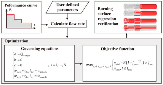
Figure 6.
Flow diagram of optimization.
3. Results and Discussions
3.1. Single-Thrust Case
The single-thrust motor is a commonly employed propulsion system in space launch vehicles. A low pressure ratio (maximum pressure to mean pressure) design can enable significant reductions in both chamber wall thickness and inert mass, providing an improved motor performance []. In this case, we will design a modular grain with a thrust of approximately 100 kN, a duration of 5 s, and a target pressure of 10 MPa. Firstly, it is necessary to determine the appropriate nozzle throat area. Assuming the thrust coefficient is 1.4, the nozzle throat area is as follows:
As the characteristic velocity c * of the propellant is given as 1400 m/s, the mass flow rate can be calculated by Equation (23).
Furthermore, in order to optimize the design, the constraints outlined in Table 2 are considered. These constraints provide guidelines and limitations for the optimization problem. In this particular case, the number of segments N is 1, indicating that the grain configuration consists of only one single segment.

Table 2.
Constrains of the optimization problem.
The optimization process for this design problem is performed using the Nelder–Mead algorithm. The optimal results obtained from the optimization process are presented in Table 3.

Table 3.
Optimal result of single-thrust grain.
The propellant loading fraction, which refers to the ratio of propellant volume to chamber volume, is determined to be 81.37%. Additionally, the throat-to-port ratio J is found to be 0.306, slightly larger than the upper limit due to:
- (1)
- The numerical process of rounding and from a floating-point number to an integer.
- (2)
- The soft-constraint nature of the penalty function in Equation (31).
The burning-to-port ratio (Po, also known as the Pobedonostsev number) can be expressed in terms of the throat-to-port ratio (J):
where is the initial total burning surface area. The calculated Po value of 60.2 (well below the critical threshold of 100) suggests that erosive burning is unlikely to occur for typical double-base propellants [].
Notably, Table 3 reveals an interesting observation that the burning rate and web thickness of star grains and slot grains are nearly identical. This suggests that both types of grains burn out simultaneously, making a more stable chamber pressure and a shorter tail-off period.
To validate the chamber pressure obtained, the Poisson equation—Eikonal equation—finite element (PEF) method is employed. This method involves solving a Poisson equation using the finite element method to approximate the viscous solution of the Eikonal equation. By transforming the burn-back analysis problem into a specialized stationary thermal conduction problem, the PEF method can be implemented by COMSOL software (version 5.6). It is particularly useful for analyzing the burn-back of three-dimensional grains with irregular geometry and a complex burning rate distribution. The internal ballistics model assumes a zero-dimensional quasi-steady state, and further details can be found in Li’s work [].
The burning surface regression is shown in Figure 7, and the pressure–time curve is shown in Figure 8.
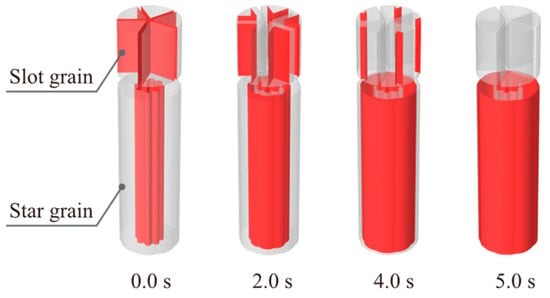
Figure 7.
Burning surface regression of the single-thrust grain.
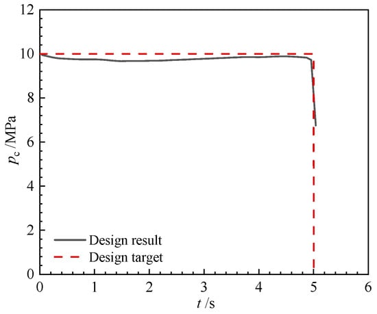
Figure 8.
Internal ballistic of the single-thrust grain.
The obtained results demonstrate a good match between the chamber pressure and the desired target, with a maximum deviation of 3.3% during the pressure platform. The relative mean squared error (RMSE) between two curves is 0.003685. Notably, both the star grain and slot grain exhibit a simultaneous burnout, resulting in a shorter tail-off. The performance matching degree can also be given by linear regression as follows []:
where and are the discretized form of designed pressure–time curve and target pressure–time curve, respectively. is a vector consisting of the mean value of . Note that r2 reflects an important aspect of the performance-matching degree. The closer r2 is to 1, the more accurately the curve shape matches the target. In engineering practice, an r2 > 0.95 demonstrates that the design captures 95% of pressure fluctuations, representing an accurate match to the target performance curve. In our single-thrust case, r2 is 0.9764 (>0.95), suggesting a very accurate match to the target performance curve.
The parametric sensitivity analysis is summarized in Table 4, where each parameter is increased by 1% to evaluate its effect on RMSE and r2. The results clearly indicate that R, , , and are the most influential parameters affecting the performance curve. These key parameters should be carefully controlled during the manufacturing process to ensure optimal performance. In contrast, the remaining parameters show a minor impact on the results.

Table 4.
Parametric sensitivity study of single-thrust grain (each parameter increased by 1% independently).
It is worth noting that the slot-grain design presents certain manufacturing challenges due to the separation of the grain into multiple independent parts by the slots. To address this issue, engineering considerations suggest that the slots should not completely penetrate the radius of the grain. Figure 9 illustrates the modified geometry of the slot grain.
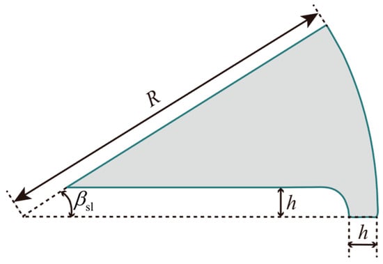
Figure 9.
Geometry of the modified slot grain.
Similarly, using the PEF method, the burning surface regression and the pressure–time curve can be obtained in Figure 10 and Figure 11.
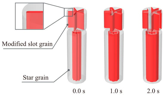
Figure 10.
Burning surface regression of the single-thrust grain (modified slot grain).
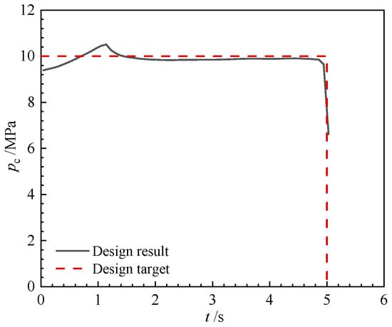
Figure 11.
Internal ballistic of the single-thrust grain (modified slot grain).
The analysis of the results reveals that the modification of the slot grain geometry from Figure 4, Figure 5, Figure 6, Figure 7, Figure 8 and Figure 9 does not significantly affect the internal ballistic performance. The new grain still maintains a good match to the target pressure curve, with a maximum deviation of less than 6.1%. The relative mean squared error (RMSE) between two curves is 0.002545. The performance matching degree (r2) calculated by Equation (34) is 0.9826, even higher than the results before slot modifications. A slight progressive burning is observed when the time t is less than 1.5 s. This progressive burning behavior can be attributed to the growth of the slot length at the beginning of the burning.
In conclusion, the single-thrust case analysis demonstrates the potential of using a modular grain design. This design allows for the production of a stable pressure platform while maintaining a high propellant loading fraction, which can be mathematically guaranteed. Building upon this finding, the subsequent section will investigate the utilization of a two-segment modular grain to achieve a dual-thrust profile.
3.2. Dual-Thrust Case
The use of a dual-thrust grain in missiles is primarily aimed at extending their flight range. This configuration consists of a boost stage and an endurance stage. While there are various methods to design a dual-thrust grain, ensuring the stability of pressure platforms is often a challenging task. In this regard, the utilization of modular grain offers a better solution.
The design objective for this particular case is to achieve a pressure of 10 MPa for a duration of 5 s, followed by a pressure of 5 MPa for an additional 5 s. The throat area of the nozzle remains constant at 0.007143 m2, and the mass flow rate during each phase can be calculated using Equation (23). The optimization problem is subject to certain constraints, as outlined in Table 2, where the number of segments N is 2. To be simple, we assume that different grain segments share the same geometry parameters, for example, .
The optimization process is conducted by the Nelder–Mead algorithm. Interestingly, it is observed that the majority of the geometry parameters remain the same as those presented in Table 3. The propellant loading fraction is 81.37%, the throat-to-port ratio is 0.306 and the burning-to-port ratio is 90.3 (<100), suggesting that erosive burning is unlikely to occur for typical double-base propellants []. However, there are differences in the burning rate and grain length, as indicated in Table 5.

Table 5.
Optimal result of dual-thrust grain.
One possible explanation is that when a fixed grain radius and a specific throat-to-port ratio are considered, the optimal solutions remain the same. It means that Table 3 provides the optimal configuration for the modular grain, which proves to be suitable not only for single-thrust scenarios but also for dual-thrust and even triple-thrust applications. Using the PEF method, the burning surface regression and the pressure–time curve can be obtained and shown in Figure 12 and Figure 13. During every phase, the relative maximum deviation between designed pressure and target pressure is 3.0%. The relative mean squared error (RMSE) between two curves is 0.001588. The performance matching degree (r2), calculated by Equation (34), is 0.9897 (>0.95), indicating a very accurate match to the target performance curve.
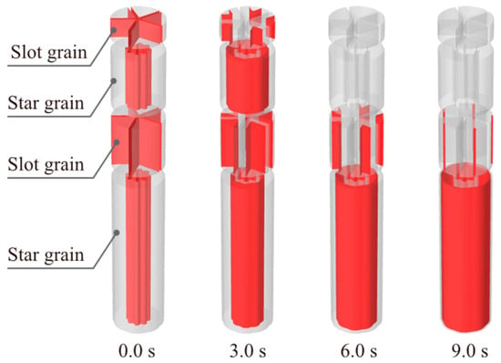
Figure 12.
Burning surface regression of the dual-thrust grain.
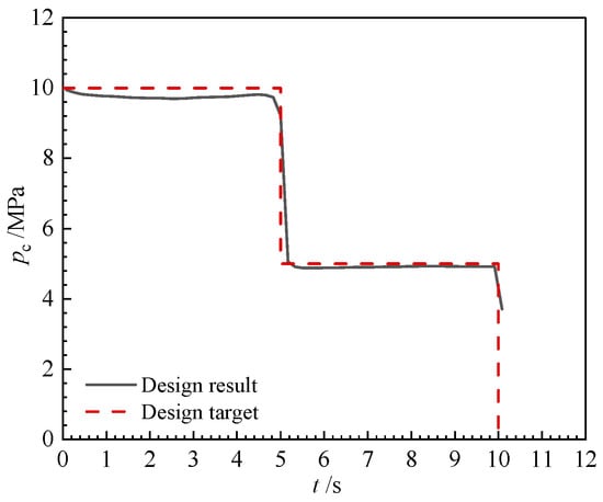
Figure 13.
Internal ballistic of the dual-thrust grain.
Due to the engineering considerations mentioned earlier, a modification has been made to the slot grain design. The resulting burning surface regression and pressure–time curve can be observed in Figure 14 and Figure 15, respectively. These graphical representations provide insights into the effects of the modified slot on the combustion process.
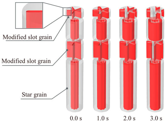
Figure 14.
Burning surface regression of the dual-thrust grain (modified slot grain).
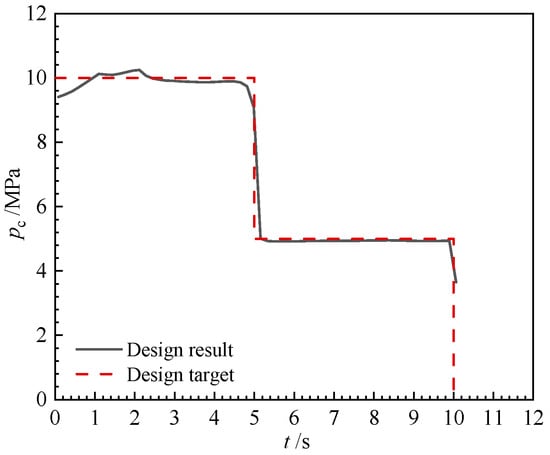
Figure 15.
Internal ballistic of the dual-thrust grain (modified slot grain).
Based on the obtained results, it is evident that the maximum deviation between the design outcome and the target is 5.9%. The relative mean squared error (RMSE) between the two curves is 0.001179. The performance matching degree (r2), calculated by Equation (34), is 0.9913 (>0.95). The modification made to the slot-grain design not only ensures its manufacturability but also enhances the initial pressure platform, resulting in a better match with the target profile.
This dual-thrust case serves as a demonstration of the capabilities of modular grain. By utilizing only two types of grain configurations, designers can effectively match the desired pressure–time curve by combining them flexibly. Moreover, the achieved pressure platform is as steady as possible, while the propellant loading fraction remains at its highest level within the given constraints.
3.3. Triple-Thrust Case
Designing a triple-thrust grain configuration poses a significant challenge. While the three-segmented modular grain theoretically has the potential to achieve the desired outcome, there is an alternative approach to consider. As shown in Figure 16, in this case, we propose replacing the third segment with an end-burning grain. This substitution may offer a viable solution in achieving the desired triple-thrust configuration.

Figure 16.
Geometry of triple-thrust grain.
The design objective is to generate a pressure of 10 MPa for a duration of 5 s, followed by a pressure of 6 MPa for 5 s, and then a pressure of 3 MPa for 10 s. In order to reduce the overall length of the grain, the allowable range for the grain radius has been adjusted from [0.05, 0.2] to [0.05, 0.25].
Since the third segment is replaced by an end-burning grain, Equation (23) needs to consider the burning of the third segment, that is,
where “ed” means the end-burning grain, and the reference burning rate can be decided by the chamber pressure of the third phase, as follows:
The length of the third segment is calculated by burning time, as follows:
The other solution process is similar to the previous sections and will not be repeated here. The burning surface regression and the pressure–time curve are shown in Figure 17 and Figure 18.
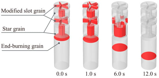
Figure 17.
Burning surface regression of the triple-thrust grain (modified slot grain).
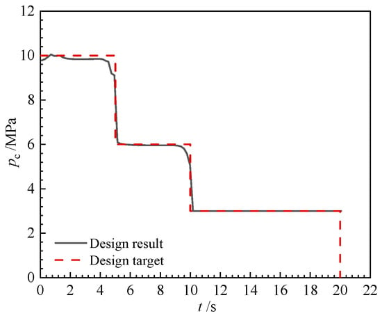
Figure 18.
Internal ballistic of the triple-thrust grain (modified slot grain).
The designed grain successfully forms the triple-thrust profile. During every phase, the relative maximum deviation between designed pressure and target pressure is 2.8%. The relative mean squared error (RMSE) between the two curves is 0.000758. The performance matching degree (r2), calculated by Equation (34), is 0.9940 (>0.95). The propellant loading fraction is 87.88%, the throat-to-port ratio is 0.301, and the burning-to-port ratio is 43.8 (<100), suggesting that erosive burning is unlikely to occur for typical double-base propellants []. It is worth noting that the transient period between phases is shorter than 1 s and there is no tail-off period at the end of burning. In this case, three types of grain templates are used, including star, modified slot, and end-burning grain, demonstrating the flexibility of modular grain.
Till now, we have examined the four features or advantages of modular grain that are highlighted in the Introduction section.
- (1)
- Simplicity of Basic Grain Shape Template: The basic template for grain shape is designed to be simple, thereby minimizing the overall complexity of the grain shape. The segmented grain technology is relatively mature, and the manufacturability of 2D grain configurations can be effectively addressed with existing techniques. In contrast, the design results of other existing grain optimization methods may be complicated and not suitable for real-world manufacturing.
- (2)
- Mathematical Assurance of Steadiness: The steadiness of the pressure platform is guaranteed by the governing equations. In contrast, other existing grain optimization methods cannot mathematically guarantee the steadiness of the results.
- (3)
- Maximization of Propellant Loading Fraction: The maximization of the propellant loading fraction is achieved by optimization.
- (4)
- Time Efficiency: As shown in Table 6, the computational time required for equation solving using Newton’s method does not exceed 24 milliseconds, while the whole optimization process takes no more than 85 s on a CPU AMD Ryzen 7 5800H. The Nelder–Mead method can obtain better results than the simulated annealing method and random search method. In contrast, other existing grain optimization methods, such as evolutionary neural networks, will take hours to finish the computation on large-scale parallel computing servers [].
 Table 6. Time cost of the triple-thrust case using different algorithms (the termination criterion is the change of the objective function value of less than 10⁻3).
3.4. Structural Strength Considerations
Modular grain designs are particularly suitable for free-standing solid rocket motors, where the propellant grain is manufactured separately and later assembled into the combustion chamber. To ensure structural integrity during combustion, an inhibitor layer must be applied to the exterior of the propellant. This layer serves two critical functions: (1) combustion suppression: preventing unintended burning on the outer surface and (2) mechanical support: providing a rigid backing structure to withstand internal stresses.
However, propellant–inhibitor debonding remains a major failure risk for modular grains, posing a significant practical challenge. To assess this risk, we performed a stress analysis on a modified slot grain configuration under 10 MPa pressure loading (from the result in Section 3.1). The finite element method (FEM) with a linear elastic material model is used. The elastic modulus of the propellant and inhibitor is 0.350 GPa and 0.280 GPa, respectively. The Poisson‘s ratio of the propellant and inhibitor are both 0.49. The simulation results (presented in Figure 19) reveal stress concentrations at the propellant–inhibitor interface, highlighting zones vulnerable to debonding during burning. The simulation results provide a basis for determining the minimum required bonding strength at the interface.

Figure 19.
The von Mise stress of the modified slot grain with different burned web thicknesses (half-star angle only).
4. Conclusions
This investigation explores the design and optimization of modular solid rocket grains matching multi-thrust performance curves. Several conclusions can be drawn from this study.
- (1)
- The concept of modular grain is introduced, consisting of star grain, slot grain, and end-burning grain as the fundamental templates (with different materials or burning rates). By combining these templates, an arbitrary multi-thrust performance curve can be achieved mathematically.
- (2)
- A governing equation system with multiple algebraic equations suitable for modular grains is developed in order to match the desired multi-thrust performance curve.
- (3)
- Optimization techniques are utilized to determine the best configuration of the modular grains in order to achieve the highest propellant loading fraction. To achieve optimal results, it is essential that each segment have the same maximum web thickness, while also ensuring that the throat-to-port ratio reaches its upper limit. The propellant loading fraction for the cases of single-thrust, dual-thrust, and triple-thrust configurations reaches 81.37%, 81.37%, and 87.88% respectively.
- (4)
- Practical implementation of our method has successfully produced single-thrust, dual-thrust, and triple-thrust grains. These grains have demonstrated the ability to maintain steady pressure platforms, making them competitive alternatives to traditional multi-thrust grains.
This theoretical work significantly simplifies the design of motor grains, especially for multi-thrust grains. By utilizing the combination of basic grain configurations, namely star, slot, and end-burning grains, complex performance curves can be mathematically guaranteed by governing equations. Future research should focus on three key aspects: (1) multi-objective optimization framework incorporating structural integrity, manufacturing constraints, and thrust stability trade-offs; (2) practical implementation of modular grain designs, focusing on manufacturability and structural integrity; and (3) the exploration of additional candidate grain (even 3D grain) configurations to serve as alternative grain templates.
Author Contributions
Conceptualization, W.L. and Y.H.; methodology, W.L. and Y.Z.; software, W.L. and Y.Z.; validation, W.L. and Y.Z.; formal analysis, W.L.; investigation, W.L.; resources, G.L.; data curation, W.L.; writing—original draft preparation, W.L.; writing—review and editing, Y.H. and G.L.; visualization, W.L.; supervision, Y.H. and G.L.; project administration, Y.H. and G.L.; funding acquisition, Y.H. and G.L. All authors have read and agreed to the published version of the manuscript.
Funding
This research received no direct external fundings.
Institutional Review Board Statement
Not applicable.
Informed Consent Statement
Not applicable.
Data Availability Statement
The original contributions presented in this study are included in the article. Further inquiries can be directed to the corresponding author(s).
Conflicts of Interest
The authors declare no conflicts of interest.
References
- Monroe, H. A High Performance, Multi-Thrust, Reusable Motor for Sled Track Propulsion. In Proceedings of the 3rd Solid Propulsion Conference, Atlantic City, NJ, USA, 4–6 June 1968. [Google Scholar]
- Shekhar, H. Burn-Back Equations for High Volumetric Loading Single-Grain Dual-Thrust Rocket Propellant Configuration. Defence Sci. J. 2011, 61, 165. [Google Scholar] [CrossRef]
- Chen, W.; Liang, G.Z. Internal Ballistic Multi-Burning-Rate Solid Rocket Motor Based on Parameterized Feature CAD Model. J. Aerosp. Power 2015, 30, 3017–3028. [Google Scholar]
- Zhou, B.H.; Wang, H.; Ruan, W.J. Internal Ballistics Design Method of Solid Rocket Motor Based on Ladder-Shaped Multiple Propellant. J. Solid Rocket. Technol. 2021, 44, 431–437. [Google Scholar]
- Raza, M.A.; Wang, L. Robust Performance Optimization of Dual Thrust Rocket Motor. Aircr. Eng. Aerosp. Technol. 2012, 84, 244–251. [Google Scholar] [CrossRef]
- El-Naggar, M.; Belal, H.M.; Abdallah, H.M. Design of a Dual Thrust Solid Motor Using Star Grains. In Proceedings of the AIAA Scitech 2021 Forum, Virtual Event, 11–15, 19–21 January 2021. [Google Scholar]
- Bu, Z.X.; Qin, G.M.; Li, H.Y. Single Chamber Multi-Thrust Solid Propellant Motors; National Defense Industry Press: Beijing, China, 2013; p. 164. [Google Scholar]
- Hashish, A.; Mohamed, M.Y.; Abdalla, H.M.; Elsanabawy, M. Design of Solid Propellant Grain for Predefined Performance Criteria. In Proceedings of the SciTech Forum, San Diego, CA, USA, 7–11 January 2019. [Google Scholar]
- Wu, Z.P.; Wang, D.H.; Zhang, W.H.; Okolo, P.N.; Yang, F. Solid-Rocket-Motor Performance-Matching Design Framework. J. Spacecr. Rocket. 2017, 54, 698–707. [Google Scholar]
- Wu, Z.P.; Wang, D.H.; Wang, W.J.; Okolo, P.N.; Zhang, W.H. Solid Rocket Motor Design Employing an Efficient Performance Matching Approach. Proc. Inst. Mech. Eng. Part G J. Aerosp. Eng. 2018, 233, 4052–4065. [Google Scholar]
- Maute, K.; De, S. Shape and Material Optimization of Problems with Dynamically Evolving Interfaces Applied to Solid Rocket Motors. Struct. Multidisc. Optim. 2022, 65, 218. [Google Scholar] [CrossRef]
- Li, W.T.; Li, W.B.; He, Y.Q.; Liang, G. Reverse Design of Solid Propellant Grain for a Performance-Matching Goal: Shape Optimization Via Evolutionary Neural Network. Aerospace 2022, 9, 552. [Google Scholar] [CrossRef]
- Li, W.T.; He, Y.Q.; Li, W.B.; Zhang, Y.; Liang, G. 3D Grain Reverse Design and Shape Optimization for Solid Rocket Motor. Acta Aeronaut. Et Astronaut. Sin. 2024, 45, 196–214. [Google Scholar]
- Li, W.T.; Li, W.B.; He, Y.Q.; Liang, G. Multi-Objective Reverse Design and Pattern Analysis of Solid Propellant Grains. Aiaa J. 2024, 62, 3914–3931. [Google Scholar] [CrossRef]
- Yang, C.G. A Brief Discussion on the Work of “Three Modernizations” in Solid Rocket Motors. Aerosp. Stand. 2002, 32–33. [Google Scholar]
- X-Bow Systems Launches Second Successful “Bolt” Rocket. Available online: https://www.prnewswire.com/news-releases/x-bow-systems-launches-second-successful-bolt-rocket-301851088.html (accessed on 22 November 2023).
- Xbow Systems. Available online: https://www.xbowsystems.com/we-build/ (accessed on 22 November 2023).
- Hartfield, R.; Jenkins, R.; Burkhalter, J.; Foster, W. A Review of Analytical Methods for Solid Rocket Motor Grain Analysis. In Proceedings of the 39th Joint Propulsion Conference and Exhibit, Huntsville, AL, USA, 20–23 July 2003. [Google Scholar]
- Nelder, J.A.; Mead, R. A Simplex Method for Function Minimization. Comput. J. 1965, 7, 308–313. [Google Scholar] [CrossRef]
- Li, W.T.; He, Y.Q.; Zhang, Y.Y.; Liang, G. Complex Burn-Back Analysis and Internal Ballistic Performance Prediction of Non-Uniform Grain. J. Beijing Univ. Aeronaut. Astronaut. 2024, 50, 2524–2537. [Google Scholar]
- Song, S.; Ren, Q.; Tang, M.; Shi, J.; Wang, J. A Study on Ultra-Low-Pressure Ratio Technology on the Basis of 3D-Printed Propellant for a Solid Rocket Motor. Aerospace 2023, 10, 862. [Google Scholar] [CrossRef]
- Arkhipov, V.A.; Zarko, V.E.; Zharova, I.K.; Zhukov, A.S.; Kozlov, E.A.; Aksenenko, D.D.; Kurbatov, A.V. Solid Propellant Combustion in a High-Velocity Cross-Flow of Gases (Review). Combust. Explos. Shock Waves 2016, 52, 497–513. [Google Scholar] [CrossRef]
Disclaimer/Publisher’s Note: The statements, opinions and data contained in all publications are solely those of the individual author(s) and contributor(s) and not of MDPI and/or the editor(s). MDPI and/or the editor(s) disclaim responsibility for any injury to people or property resulting from any ideas, methods, instructions or products referred to in the content. |
© 2025 by the authors. Licensee MDPI, Basel, Switzerland. This article is an open access article distributed under the terms and conditions of the Creative Commons Attribution (CC BY) license (https://creativecommons.org/licenses/by/4.0/).