Abstract
External fixators are frequently used to treat complex fractures with multiple bone fragments and soft tissue injuries. Inaccurate assessment of bone union and premature removal of the fixator may necessitate revisions and prolong treatment. The decision to remove an external fixator typically depends on an orthopedist’s experience. The accuracy of diagnosis can be improved by using a force sensor integrated into the modified external fixator according to Mitkovic. A sensor measuring axial compressive force is mounted between two vertical rods. Experiments with the modified external fixator were carried out using three different axial loads delivered by the universal electromechanical testing machine (UETM) and a sensor that detected the corresponding axial force. Springs with variable rigidity were used to simulate bone callus stiffness. Low rigidity springs represented a high elasticity callus, whereas high rigidity springs represented a callus with lower elasticity. The results show that the force detected by the sensor was nearly identical to the force delivered by the UETM while the callus did not form, decreased as spring rigidity increased, and eventually zeroed out as the leg healed. The findings indicated that using modified external fixator according to Mitkovic can help orthopedists assess bone healing more accurately.
1. Introduction
A bone fracture can be partial or complete and is usually caused by a fall from a height, accident, osteoporosis, and overuse [1]. In [2], the authors describe four phases of secondary bone fracture healing: hematoma formation (1–2 weeks), granulation tissue formation (2–4 weeks), bone callus formation (4–8 weeks), and bone remodeling (8–12+ weeks). Callus is the new bone tissue formed at the fracture site. It is elastic and hardens over time, reaching the stiffness of healthy bones by the end of healing. The callus deflection is greatest at the beginning and the lowest at the end of healing, when it is equivalent to the deflection of a healthy bone.
The bone healing process requires a short distance between fracture fragments with very small freedom of movement until new bone tissue develops. Until the twentieth century, immobilization was the primary technique to hold bone fragments in place. Bone fixation implants emerged with the development of medicine. There are two types of severe bone fracture fixation. Internal fixation involves inserting the entire fixation implant under the skin, while external fixation uses pins inserted into the bone, passed through the soft tissues and skin, and attached to a frame outside the body [3]. Discomfort and possible pin tract infection are considered disadvantages of external fixation [4]. An external fixator, according to Mitkovic, is a minimally invasive 3D fixation system typically used to treat open fractures with a higher risk of infection, complex fractures, and fractures with severe trauma of the surrounding nerves and blood vessels [5]. It consists of bars, adjustable clamps, and clamp-carriers designed to be highly adaptable to different fracture fragments position.
Long bones fractures (femur, tibia, etc.) are the most common types of injuries that, in addition to expected discomfort, can lead to reduced or lost limb function [6,7,8] and, also, to complications such as deep infection, vascular or nerve damage [9], delayed union, malunion, and nonunion [10,11,12,13]. Delayed union occurs when bone does not heal at the expected rate, malunion is followed by bone healing but not in the proper position, whereas nonunion occurs when broken fragments fail to be connected by the new bone [10]. The authors of [11] conducted a study on the rate and predictions of patient readmission for surgical treatment due to bone healing complications (8% of patients were readmitted to the hospital). In [12], the authors found that vulnerability of the soft tissues surrounding the fracture increases the susceptibility to non-union and infection. The authors of [13] discuss a morbidity associated with a long bone nonunion. In addition, several studies [14,15,16,17] discuss emergency fracture care in cattle orthopedics. The authors of [14,15,17] discuss external skeletal fixation (ESF) as a rigid immobilization, while the author of [16] discusses long bone fractures complications. However, the external fixation on the cattle is outside of the scope of this study.
Integration of a sensor technology into the external fixator is a strategy that provides a more accurate decision on bone healing. A modified external fixator according to Mitkovic is an electrically active system in which force is detected by a sensor integrated into the existing structure [18]. At the beginning of the treatment, the sensor readings correspond to half of the patient’s weight, implying that the broken leg was not loaded. When the callus hardens, the sensor deflection changes due to the axial load. As the force in the leg increases the force detected by the sensor drops to near-zero levels.
In the experiments, three different axial loads delivered by the Shimadzu universal electromechanical testing machine (UETM) (50 N, 250 N, and 500 N) are compared with axial forces detected by the sensor, with three springs of different rigidity (k = 1.5 N/mm, k = 3.8 N/mm, and k = 7.5 N/mm) used to simulate different stages of callus hardening [2]. The results show that the force detected by the sensor was almost identical to the force delivered by the UETM (k = 0 N/mm) and decreased as the spring rigidity increased. When the patient fully recovers, the sensor detects only minor elastic deformation caused by deflection of the bone and weight of fixator parts located above the sensor.
From a technical perspective, the fixator may be removed when sensor reading approaches zero. However, from a medical perspective, the choice to remove the fixator is influenced by the orthopedist’s subjective assessment. The results of this research indicate that the functional upgrades to the external fixator according to Mitkovic corroborate the evaluations made by orthopedists. An objective approach to using data from the sensor can facilitate clinical decision-making. It is important to highlight that the findings discussed in this article are based on mechanical tests, with plans for clinical trials to be carried out in the future.
2. Related Work
External fixator systems are characterized by their simplicity and versatility of use, ability to reduce soft-tissue damage, stability at the bone screw interface, and rigidity [19]. The decision to remove an external fixator is typically based on the interpretation of clinical results and the experience of an orthopedist. In [20] the authors discuss the lack of standardized methods for assessing bone union that result in significant disagreements among orthopedists in both clinical practice and research. Currently, X-rays and magnetic resonance imaging are the primary but unsafe diagnostic tool used to assess the callus formation and the mechanical stability of the bone. Other clinical evaluation parameters assessed by the orthopedist include the pain, soft tissue healing, (in)stability of the patient, and weight bearing [21]. In addition, mechanical assessment tools can be used to decide about the stiffness of the callus from the early stages of its formation until complete union. Direct methods (i.e., assessing the fracture stiffness by measuring the deflection at the fracture site) have the major disadvantage of removing the external fixator for each measurement. Indirect approaches (i.e., measuring strain via external fixation) have been more extensively applied. However, only a few studies have examined the displacement of external fixator components as a mean of monitoring the fracture healing.
In [22] the authors present design of a dynamic external fixator system used to treat open tibial fractures. It consists of an inner rod with axial motion in the outer tube for dynamization to improve bone healing. Clamps for rods and tube provide six degrees of freedom. An open clamp is designed to limit tube movement. Distal nuts are used for bone gap closure function. This design is developed based on the benefits of dynamization (a gradually decreasing construct-stability of a fixator as a therapy used for the final phase of fracture healing), increased union rate and the simplicity of mono-lateral frame. It is simple to use, safe, and provide a stable structure in which rigidity and alignment can be adjusted as needed during the treatment. In [23], the authors describe three-step dynamization of the hexapod circular external fixator that is primary based on the experience of an orthopedist, with no set criteria. The first step is to loosen two struts arbitrarily, then remove the loosened struts, and finally remove the remaining struts one at a time. The authors of [24] propose a non-invasive method based on changes in stress transmission, the location of stress-sensitive points, and the displacement in an external fixator system during healing process of tibial fractures. Their research focuses on developing finite element models for fractures treated with unilateral external fixation. The intersections of the lowest screw and the bone cortex, as well as the second screw and the connecting rod, can be used as sensitive points for monitoring the healing. As a next research step, the authors propose investigating the feasibility of placing non-invasive, compact sensors on external fixators. This can assist orthopedists to accurately assess fracture healing, allowing for more informed treatment decisions, including removal of the external fixator.
The orthopedist can remove the vertical rod of the fixator to check the bone healing process. If the pain persists during the orthopedist’s manual pressure at both sides of the fixator, the vertical rod should be reinserted into the device and treatment should be continued. To facilitate the assessment of the callus hardening without requiring numerous X-ray images, we have modified an external fixator according to Mitkovic [25] that detects micromovements between bone fragments and have provided data on callus elasticity based on sensor readings.
3. Modified External Fixator According to Mitkovic
In [25], the authors describe an external fixator according to Mitkovic as an external fixator that allows for gradual reduction in fixation stiffness and leads to a high rate of successful healing. The fracture fixation device facilitates the achievements of a balanced 3D wedge configuration at an angle of 90°, as well as at any other desired angle [26]. This design represents the simplest concept of external fixation, consisting of a road, clamp carriers, clamps, and pins, which can be interconnected in various configurations to form frames suitable for all trauma care requirements, primarily those that are complex and have associated soft tissue damage [27,28]. An external fixator according to Mitkovic is shown in Figure 1a. However, despite the fact that this fixator has a number of benefits, precise indicators for its removal have yet to be properly established [18]. The modified external fixator according to Mitkovic is shown in Figure 1b.
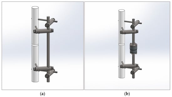
Figure 1.
External fixators: (a) external fixator according to Mitkovic; (b) modified external fixator according to Mitkovic.
The sensor is a cylinder with threaded holes on both its upper and lower surfaces, built-in between two vertical rods connecting the upper and lower parts of the supporting structure. The measuring unit is a steel loaded element with mounted strain gages. Flanges are attached to the ends of the rods and are connected to the upper and lower sides of the sensor. With this design, there is no need to loosen the screws in the clamps fixing the parts of the vertical rod during the recovery period. The disadvantage of the design is that it does not prevent the sensor from being loaded by a bending moment resulting from eccentric action of axial comprehensive force. The alternative that best fits the experimental settings is the bending moment determined by the patient’s weight. A sensor capable of measuring forces up to 10 kN (~1000 kg weight) can withstand a bending moment of 120 Nm. The compressive axial loads are related to the distances between two parts of the fractured bone. The sensor unit can be easily integrated with the external fixator and used to distinguish the external wedges relative displacements to provide information on the callus stiffness, determined as follows:
where d represents the displacement and F represents the force exerted through the leg.
For the purpose of this research, the U93A force sensor is used to detect small changes in force and to convert mechanical stimuli into an electrical signal, in response to the force exerted trough the leg [18]. The sensor dimensions are Φ35 × 30. It has four M5 threaded holes on the upper and lower surfaces. The U93A models with 0–10 V or 4–20 mA configurations are available, as well as a digital module featuring an I/O-link interface. A significant feature of this sensor is the 0.05 mm deflection at the full load.
Since the sensor does not measure force directly but detects it through deflection, calibration is performed before use, through the manufacturer’s application. When an axial load is applied, the measurement body deforms, which leads to strain near the strain gages. These gages are configured to create a Wheatstone bridge circuit, generating an output signal proportional to the variation in resistance and, consequently, the magnitude of the force, when it is under voltage. The relationship between the force F [N] and the sensor sensitivity S [mV/V] is linear (). The calibration factor k is determined by manufacturer based on two reference points: the origin and the maximum nominal load of 10 kN, which corresponds to a generated electrical signal of 1.2144 mV/V (Figure 2).
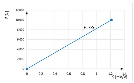
Figure 2.
Relation between axial force and sensor sensitivity.
The sensor is connected to a smartphone or tablet via Bluetooth and a free app, allowing measurement results to be displayed and recorded for future data analysis. The communication module is connected to the sensor via cable and has its own power supply (it is also power supply for the sensor).
A Mantracourt B24-SSBC-A (B24) is used for wireless transmission between the sensor and a mobile device. The B24 telemetry strain bridge sensor transmitter is designed to provide measurement systems with user-friendly access (C style enclosure with integrated battery). It enables strain measurements at close range allowing immediate engagement with data and projects. Effective power electronic provides high input sensitivity of ±6 mV/V, ±12 mV/V, ±24 mV/V, and ±48 mV/V. It aims to work for up to 3 months of continuous use of three samples per second for a close range up to 90 m, and ideally up to 12 transmitters by a single device. The transmission rate is adjustable from 10 times/second to once per 10 s. The B24 can be calibrated in kilograms and other weight units such as tons or pounds. The B24 iOS and Android App for B24 Bluetooth Transmitter interface (B24 App) generate dashboards for hands-on measurements, and display data from the strain bridge module directly on Android or iOS. In addition, the B24 App creates real-time measuring projects and can select 5 different tiles to customize dashboard. Data can be expressed as mathematical equations to describe exactly what is displayed. The B24.NET Driver Pack contains. NET drivers for configuring and calibrating B24 modules from a PC.
4. Experimental Results
The experiments were carried out in March and April 2025, at the Faculty of Mechanical Engineering, University of Nis. The objective of the experiments was to analyze the design and operational aspects of the modified fixator as a means for qualitatively assessing the healing of fractured bones.
4.1. Experiment Setup
The experiments are conducted on a fixator equipped with a U93A sensor. A sensor design sensor includes flanges that precisely match the sensor’s upper and lower surfaces. The connection is secured with four M5 screws to replicate real-world conditions; the rod and sensor are fixed until the end of the treatment.
The Shimadzu computer-controlled UETM is used to measure the compressive axial load. The UETM with the sensor inserted between joints for compression tests is shown in Figure 3a. Sensor inserted in the middle of the vertical rod is shown in Figure 3b.
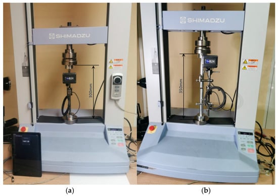
Figure 3.
Experimental setup for testing the modified external fixator according to Mitkovic. (a) The sensor is inserted between the joints of UETM. (b) The sensor is integrated in the middle of the vertical rod.
UETM is suitable for extensive testing of metallic and non-metallic materials in tension, compression, bending, torsion, friction, peel, adhesion, and penetration. The stress and strain are easily controllable with a Jog controller that allows hand-held control of the crosshead position. The Jog dial makes fine positioning easy. A built-in main operational panel enables the development and storing of test conditions, allowing testing without having to connect to the PC. The UETM comes with the industry-leading TRAPEZIUM X data processing software, which offers an unrivaled level of performance and provides improved productivity and efficiency for quality control operations. Since TRAPEZIUM X and the B24 App enable data recording and processing, it is possible to confirm that modified external fixator according to Mitkovic provides better monitoring of bone recovery processes. In qualitatively superior level, the bone union process is monitored and the moment when the use of the fixator is unnecessary is determined (i.e., fixator removing).
4.2. Measurements of Axial Loads
When a bone breaks, the body begins to form an elastic callus to heal the fracture. The callus hardens over time, reaching the stiffness of healthy bone by the end of recovery. The bone callus stiffness is simulated by springs of various rigidity: k = 0 N/mm, k = 1.5 N/mm, k = 3.8 N/mm, and k = 7.5 N/mm, which correspond to the four phases of secondary healing [2]. More detailed explanations can be found in [29,30,31,32]. To limit variability in geometry and mechanical properties, two 25 mm diameter aluminum rods are used to simulate a broken bone and injured tissues. Because stiffness and elasticity are inversely proportional, a low rigidity spring simulates a high elasticity callus during the early stages of bone union. A high rigidity spring simulates the callus with reduced elasticity and increased stiffness. Bonded connections are used to simulate the joints between the elements of the fixator.
Since no medical data on the load level applied to the external fixator according to Mitkovic was available, the UETM was used to deliver loads by increasing compressive axial force from 0 to 300 N and then decreasing it back to 0 N every 0.5 s. Small variations in forces delivered by UETM and measured by the sensor were detected (See Figure 4).
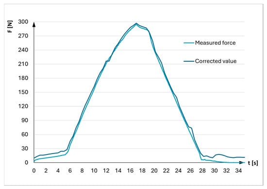
Figure 4.
Correction of force generated by UETM.
The accuracy of the UETM control software was verified at the very beginning to minimize measurement errors when comparing the force exerted by the UETM with the force detected by the sensor placed between its joints (Figure 3a). The sensor reading served as a reference point. The result indicated that the force delivered by the UETM was slightly higher than the reference value. A correction factor of 1.0164 was determined by comparing these values. Therefore, the force values delivered by the UETM were adjusted by dividing them by this correction factor during experiments.
4.3. Experiments on Modified External Fixator According to Mitkovic
Experiments with the modified external fixator are conducted using three different axial loads delivered by the UETM (50 N, 250 N, and 500 N), which corresponds to the patient’s ability to tolerate pressure in the injured leg until the onset of pain. When leaning feet, the patient slowly alternates between loading the bones of healthy and injured leg. The value of this load ranges from zero, when the foot has no contact with the ground, up to its maximum when foot bears the entire weight of the body.
The simulation of slow leaning towards the feet is performed by gradually applying three forces delivered by the UETM at 0.5 s intervals, ranging from 0 to 50 N, 250 N, or 500 N, and then returning to zero. Different callus stiffnesses are estimated by measuring for each spring, including one without a spring. Each measurement is conducted twice, resulting in a total of 24 experiments.
Figure 5, Figure 6 and Figure 7 show a comparative view of forces that load the fixator, which are delivered by the UETM and represent the weight of the patient, as well as values of the forces measured by the sensor at different loads and different rigidity of the springs (12 measurements in total).
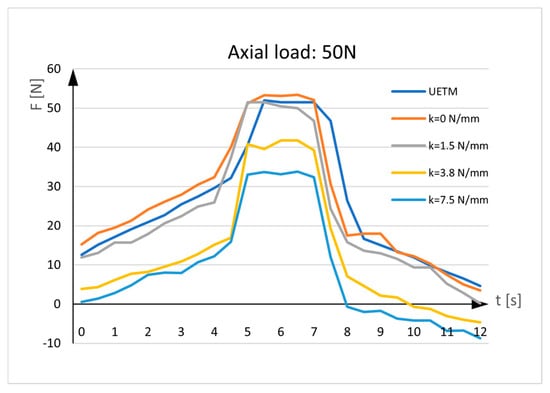
Figure 5.
Sensor measurements. UETM load: 50N.
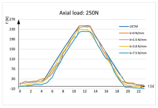
Figure 6.
Sensor measurements. UETM load: 250N.
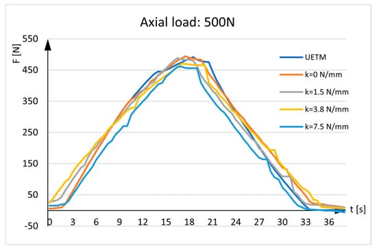
Figure 7.
Sensor measurements. UETM load: 500N.
The diagrams given in the figures have the same shapes and imply that force measured by the sensor is almost identical to the force delivered by the UETM when k = 0 N/mm. The diagrams change due to the different load values delivered by the UETM, the different time periods required to increase and decrease the force from zero to its maximum value, and rigidity of springs. It should be noted that, when the springs are positioned between the aluminum rods, they are under strain, and forces measured by the sensor deviate from the forces delivered by the UETM, which rise with spring rigidity. As the spring returns to its neutral position, it pulls the rods aside, delivering load transfers to the sensor and resulting in tensile stress. Because the sensor tends to elongate, the force values represented in the diagrams tend to show negative values.
Figure 8 shows the measurement in real situations. The results depict a patient’s gradual leaning on the injured leg until the leg bears half a weight (the patient’s weight is evenly distributed on both legs). As load-bearing capacity improves, the force measured by the sensor decreases. A horizontal line represents half of the patient’s weight.
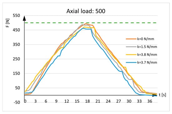
Figure 8.
Axial load: 500N. The green line represents the maximum weight of one leg.
Figure 8 also depicts recovery with the curvilinear lines, representing the force detected by the sensor. The curves are distinct from the horizontal line and approach the x-axis (y = 0). When the patient fully recovers, the sensor recording will not be zero because the bone will always have minor elastic deformation, there are axial deflection of the bone, and there will be an influence from the weight of fixator parts located above the sensor.
4.4. Discussion
The diagrams displaying the results of force measurement without springs show that the force values delivered by the UETM and measured by the sensor are nearly identical. Certain variations are caused by elastic deformations of the fixator parts connecting to the aluminum rods and the sensor itself, as well as the pins, clamps, and the upper and lower vertical rods. Moreover, the rods and the sensor are subjected to complex stresses that include both axial pressure and bending.
Force measurements with springs are more realistic, since they take into account callus hardening through the recovery period. The diagrams illustrate that the values of the forces measured by the sensor are smaller than the values of the forces delivered by the UETM, with the difference increasing as spring rigidities increase. These deviations are expected and desirable since, from a medical standpoint, they indicate callus hardening.
There are no established diagnostic criteria at this point of the research to evaluate sensor data concerning a clinical threshold that would convert sensor data into practical decisions and provide objective measurements. The interpretation of these data still depends on the orthopedist’s experience. Further evaluation of sensor-based external fixation is necessary before it can be widely used in clinical practice.
5. Conclusions and Further Work
Classical diagnostic approaches for determining full recovery after a long bone fracture do not provide precise information about whether the bone has healed completely. The assessment on fixator removal is mostly based on orthopedist’s experience and X-ray images. Occasionally, after diagnostic tests indicated the healing process was supposed to be completed and the fixator should be removed, patients return to hospital because of discomfort, pain, and/or infection. A modified external fixator, according to Mitkovic, provides the orthopedist with accurate data based on sensor measurements of change in the compressive force.
Experiments with the modified external fixator were carried out using three distinct axial loads delivered by the UETM, which simulated patient’s ability to lean to the leg until pain occurred, and a sensor that measured the resulting force. Springs of varying rigidity were used to imitate bone callus stiffness. Low rigidity springs depicted a high elasticity callus, whereas high rigidity springs replicated a callus with reduced elasticity and increased stiffness. The results showed that the force detected by the sensor was nearly identical to the force delivered by the UETM for k = 0 N/mm and decreased as spring rigidity increased.
As the next research step, the modified external fixator according to Mitkovic is planned to be used in the clinical practice of medical co-authors in real-world situations.
Furthermore, the modified external fixator is planned to be upgraded with communication equipment for remote data transmission of axial load measurements. Remote transmission eliminates the need for the orthopedist and the patient to be present at the same place during periodic check-ups. The benefits to the patient include enhanced comfort, reduced stress and a variety of others. The results on bending and axial compressive force over time provide information on the dynamics of callus hardening. These data can be used to build machine learning models, which could predict the patient’s recovery time. In this way, it would be possible, for example, to estimate the costs of treatment, absenteeism from the workplace due to injury, and so forth. Artificial intelligence algorithms can also be used for data processing and decision-making. Given data can be integrated with digital health platforms to facilitate remote monitoring and data sharing. Data analysis could be later used for different medical applications. It is important to note that processing and transmitting personal data necessitate data protection, which implies the use of cryptographic algorithms.
In some severe cases, where the bone must be stretched, a relative gradual axial separation of bone parts over time intervals with a distance proportional to the bone union may be performed. This can be accomplished by using screws built into the modified fixator to transform rotational movement into a rectilinear one. The screw can be tuned by orthopedist or automatically using a small, sensitive stepper motor actuator (SMA) at a specified angle to separate bone parts dependent on the angle of rotation and the step of the coil. SMA consists of a synchronous stepper motor that moves in discrete steps, a mechanical transmission mechanism that converts the motor’s rotary motion into the linear motion, and a control system that manages the stepper motor operations. The communications protocols used to control stepper motors are IEEE 802.x, TCP/IP, and UDP. SMA control can be implemented using a variety of microcontroller chips with Wi-Fi interfaces, such as Microchip PIC16F (Microchip Technology, Chandler, Arizona, USA) and Espressif System ESP 8266 (Espressif Systems, Shanghai, China).
Last but not least, there is some possibility for using the modified external fixator on cattle’s long bones to improve clinical management of selected fractures. However, it should be kept in mind that this structure should be customized to the specific use on livestock.
Author Contributions
Conceptualization, V.A., R.P., M.M. (Miodrag Manić), M.M. (Milan Mitković) and D.P.; methodology, V.A., M.M. (Miodrag Manić), N.K. and M.M. (Milan Mitković); validation, M.M. (Miodrag Manić), R.P., D.P. and M.M. (Milan Mitković); formal analysis, G.O., S.S., M.M. (Miodrag Manić), M.M. (Milan Mitković), N.K. and D.K.; investigation, V.A., N.K. and D.P.; resources, S.S., G.O. and M.M. (Miodrag Manić); data curation, D.K., M.M. (Miodrag Manić) and R.P.; visualization: D.P., V.A., R.P. and N.K.; writing—original draft preparation, V.A., D.P., R.P., M.M. (Miodrag Manić), M.M. (Milan Mitković), G.O., S.S. and D.K.; writing—review and editing V.A., D.P., R.P., M.M. (Miodrag Manić), M.M. (Milan Mitković), G.O., S.S. and D.K.; supervision, M.M. (Miodrag Manić), M.M. (Milan Mitković) and S.S.; funding acquisition, G.O., S.S. and D.K. All authors have read and agreed to the published version of the manuscript.
Funding
This research was funded by the Provincial Secretariat for Higher Education and Scientific Research of Autonomous Province of Vojvodina, Serbia, through project (contract number 003077303 2024 09418 003 000 000 001/2).
Institutional Review Board Statement
Not applicable.
Informed Consent Statement
Not applicable.
Data Availability Statement
Dataset available on request from the authors.
Acknowledgments
The authors thank the Provincial Secretariat for Higher Education and Scientific Research of Autonomous Province of Vojvodina, Republic of Serbia.
Conflicts of Interest
The authors declare no conflicts of interest.
References
- Court-Brown, C.M.; Bugler, K.E.; Clement, N.D.; Duckworth, N.D.; McQueen, M.M. The epidemiology of open fractures in adults. A 15-year review. Injury 2012, 43, 891–897. [Google Scholar] [CrossRef] [PubMed]
- Sheen, J.R.; Mabrouk, A.; Garla, V.V. Fracture healing overview. In National Library of Medicine; StatPearls Publishing: Treasure Island, FL, USA, 2023. Available online: https://www.ncbi.nlm.nih.gov/books/NBK551678/ (accessed on 13 May 2025).
- Fernando, P.L.N.; Abeygunawanardane, A.; Wijesinghe, P.C.I.; Dharmartne, P.; Silva, P. An engineering review of external fixators. Med. Eng. Phys. 2021, 98, 91–103. [Google Scholar] [CrossRef]
- Hoenig, M.; Gao, F.; Kinder, J.; Zhang, L.Q.; Collinge, C.; Merk, B.R. Extra-articular distal tibia fractures: A mechanical evaluation of 4 different treatment methods. J. Othopedic Trauma 2010, 24, 30–35. [Google Scholar] [CrossRef]
- Mitkovic, M.B.; Bumbasirevic, M.; Golubovic, Z.; Micic, I.; Mladenovic, D.; Milenkovic, S.; Lesic, A.; Bumbasirevic, V.; Pavlovic, P.; Karalejic, S.; et al. New concept in external fixation. Acta Chir. Jugosl. 2005, 52, 107–111. [Google Scholar] [CrossRef] [PubMed]
- Cordelle, M.Z.; Snelling, S.J.; Mouthuy, P.A. Skeletal muscle tissue engineering: From tissue regeneration to biorobotics. Cyborg Bionic Syst. 2025, 6, 0279. [Google Scholar] [CrossRef]
- Court-Brown, C.M.; Rimmer, S.; Parkash, U.; McQueen, M.M. The epidemiology of open long bone fractures. Injury 1998, 29, 529–534. [Google Scholar] [CrossRef]
- Bisaccia, M.; Cappiello, A.; Meccariello, A.; Meccariello, L.; Rinonapoli, G.; Falzarano, G.; Medici, A.; Ibaney Vicente, C.; Piscitelli, L.; Stano, V.; et al. Nail or plate in the management of distal extra-articular tibial fractures, what is better? Valutation of outcomes. SICOT-J 2018, 4, 2. [Google Scholar] [CrossRef]
- Gai, Y.; Yin, Y.; Guan, L.; Zhang, S.; Chen, J.; Yang, J.; Zhou, H.; Li, J. Rational design of bioactive materials for bone hemostasis and defect repair. Cyborg Bionic Syst. 2023, 4, 0058. [Google Scholar] [CrossRef]
- Schindler, C.R.; Mazi, I. Long bone fractures. In Acute Care Surgery in Geriatric Patients; Petrone, P., Bratwaite, C.E., Eds.; Springer: Cham, Switzerland, 2023; pp. 241–251. [Google Scholar] [CrossRef]
- Ekegren, C.L.; Edwards, E.R.; De Steiger, R.; Gabbe, B.J. Incidence, cost and predictors of non-union, delayed union and mal-union following long bone fracture. Int. J. Environ. Res. Public Health 2018, 15, 2845. [Google Scholar] [CrossRef]
- Noorlander-Borgdorrf, M.P.; Sekercan, A.; Young-Afat, D.A.; Bouman, M.; Botman, M.; Ginnakkopoulos, G.F. Nationwide study on open tibial fractures in the Netherlands: Incidence, demographics and level of hospital care. Injury 2024, 55, 111487. [Google Scholar] [CrossRef]
- Nicholson, J.A.; Makaram, N.; Simpson, A.H.R.W.; Keating, J.F. Fracture nonunion in long bones: A literature review of risk factors and surgical management. Injury 2021, 52, S3–S11. [Google Scholar] [CrossRef]
- Adams, S. The role of external fixation and emergency fracture management in bovine orthopedics. Vet. Clin. N. Am. Food Anim. Pract. 1985, 1, 109–129. [Google Scholar] [CrossRef]
- Vogel, S.; Anderson, D. External skeletal fixation of fractures in Cattle. Vet. Clin. N. Am. Food Anim. Pract. 2014, 30, 127–142. [Google Scholar] [CrossRef] [PubMed]
- Irvine-Smith, G. External skeletal fixation. Presented at the World Small Animal Veterinary Association World Congress Proceedings, Cape Town, South Africa, 16–19 September 2014.
- Sellahewa, T.; Weerashinghe, C.; Silva, P. Biomechanical evaluation method to optimize external fixator configuring in long bone fractures—Conceptual model and experimental validation using pilot study. Appl. Sci. 2021, 11, 8481. [Google Scholar] [CrossRef]
- Antic, V.; Misic, D.; Manic, M. Strain sensor-based monitoring of smart orthopedic devices in lower limb fracture healing: A review. Innov. Mech. Eng. 2023, 2, 17–41. [Google Scholar]
- Kouassi, K.J.E.; Cartiaux, O.; Fonokue, L.; Detrembleur, C.; Cornu, O. Biomechanical study of a low-cost external fixator for diaphyseal fractures of long bones. J. Orthop. Surg. Res. 2020, 15, 247. [Google Scholar] [CrossRef] [PubMed]
- Cunningham, B.P.; Brazina, S.; Morshed, S.; Miclau, T. Fracture healing: A review of clinical, imaging and laboratory diagnostic options. Injury 2017, 48, 69–75. [Google Scholar] [CrossRef]
- Sorriento, A.; Chiurazzi, M.; Fabbri, L.; Scaglione, M.; Dario, P.; Ciuti, G. A novel capacitive measurement device for longitudinal monitoring of bone fracture healing. Sensors 2021, 21, 6694. [Google Scholar] [CrossRef]
- Suksathien, Y.; Suksathien, R. Clinical study of a new design multifunction dynamic external fixation system for open tibial fracture. J. Med. Assoc. Thail. 2011, 94, 1084–1088. [Google Scholar]
- Mao, Y.; Lin, Q.; Yang, Q. The relation between the dynamization of hexapod circular external fixator and tibial mechanical properties. Orthop. Surg. 2023, 15, 1677–1684. [Google Scholar] [CrossRef]
- Jia, X.; Shen, C.; Luo, B.; Yang, Y.; Zhang, K.; Deng, Y.; Wen, J.; Ma, L. How does the stress in the fixation device change during different stages of bone healing in the treatment of fractures? A finite element study of external fixation for tibial fractures. Orthop. Surg. 2024, 16, 2821–2833. [Google Scholar] [CrossRef]
- Milenkovic, S.; Mitkovic, M.M.; Mitkovic, M. External fixation of segmental tibial shaft fractures. Eur. J. Trauma Emerg. Surg. 2020, 46, 1123–1127. [Google Scholar] [CrossRef]
- Milenkovic, S.; Mitkovic, M.M. External fixation of extra-articular open tibial fractures. Acta Fac. Medicae Naissensis 2018, 35, 330–336. [Google Scholar] [CrossRef]
- Mitkovic, M.B.; Bumbasirevic, M.; Lesic, A.; Golubivic, Z. Dynamic external fixation of comminuted intra-articular fractures of the distal tibia (type C pilon fractures). Acta Orthop. Belg. 2003, 68, 508–514. [Google Scholar]
- Mitkovic, M. Primena Metode i Aparata po Mitkoviću. In Spoljna Fiksacija Kod Preloma Tibije; Srpska akademija nauka i umetnosti Ogranak u Nišu: Niš, Serbia, 2020; Available online: https://www.mitkovic.org/news/pdf/IZVODZASAJT.pdf (accessed on 17 May 2025).
- Ghiasi, M.S.; Chen, J.E.; Rodrigez, E.K.; Vaziri, A.; Nazarian, A. Computational modeling of human bone fracture healing affected by different conditions of initial healing stage. BMC Musculoskelet. Disord. 2019, 20, 562. [Google Scholar] [CrossRef]
- Liu, Y.; Cai, F.; Liu, K.; Zhang, X.; Li, H.; Fu, X.; Zhang, T.; Yusufu, A. Bony callus stiffness indirectly evaluated by the axial load-share ratio in vivo as a guide to removing a monoliteral external fixator safety. Int. Orthop. 2021, 45, 3015–3023. [Google Scholar] [CrossRef]
- Steiner, M.; Claes, L.; Ignatius, A.; Simon, U.; Wehner, T. Numerical simulation of callus healing for optimization of fracture fixation stiffness. PLoS ONE 2014, 9, e101370. [Google Scholar] [CrossRef]
- Burny, F.; Burny, W.; Donkerwolcke, M.; Behrens, M. Effect on callus development on the deformation of external fixation frames. Int. Orthop. 2012, 36, 2577–2580. [Google Scholar] [CrossRef][Green Version]
Disclaimer/Publisher’s Note: The statements, opinions and data contained in all publications are solely those of the individual author(s) and contributor(s) and not of MDPI and/or the editor(s). MDPI and/or the editor(s) disclaim responsibility for any injury to people or property resulting from any ideas, methods, instructions or products referred to in the content. |
© 2025 by the authors. Licensee MDPI, Basel, Switzerland. This article is an open access article distributed under the terms and conditions of the Creative Commons Attribution (CC BY) license (https://creativecommons.org/licenses/by/4.0/).